1
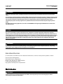
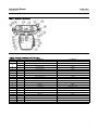
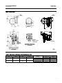
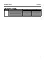
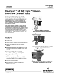
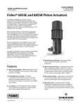
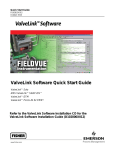
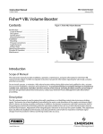
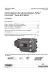
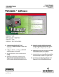
Instruction Manual
51000 Valve
D103365X012
October 2014
Baumann™ 51000 Low Flow Control Valve
Contents
Introduction . . . . . . . . . . . . . . . . . . . . . . . . . . . . . . . . . . .
Scope of Manual . . . . . . . . . . . . . . . . . . . . . . . . . . . . .
Safety Precautions . . . . . . . . . . . . . . . . . . . . . . . . . . .
Educational Services . . . . . . . . . . . . . . . . . . . . . . . . .
Maintenance . . . . . . . . . . . . . . . . . . . . . . . . . . . . . . . . .
Installation . . . . . . . . . . . . . . . . . . . . . . . . . . . . . . . . . .
Actuator Removal . . . . . . . . . . . . . . . . . . . . . . . . . . .
Plug and Packing Replacement . . . . . . . . . . . . . . . . .
Valve Disassembly . . . . . . . . . . . . . . . . . . . . . . . . . . .
Valve Reassembly . . . . . . . . . . . . . . . . . . . . . . . . . . . .
Parts Ordering . . . . . . . . . . . . . . . . . . . . . . . . . . . . . . . .
Dimensions and Weights . . . . . . . . . . . . . . . . . . . . . . .
1
1
2
2
2
3
3
4
4
5
6
9
Figure 1. 51000 NPS 1/2 Control Valve with
Baumann 16 Actuator, and FIELDVUE™ DVC2000
Digital Valve Controller
W9066
Introduction
The Baumann 51000 control valve (figure 1) is optimally designed for demanding low flow control and is a perfect fit
where space is at a premium. This compact package provides the connection integrity of flanged body globe valves,
while being significantly lighter and easier to install.
Scope of Manual
This instruction manual includes installation, maintenance, and parts information for the 51000 control valve and
Baumann 16 actuator.
Do not install, operate, or maintain Baumann 51000 control valves without being fully trained and qualified in valve,
actuator, and accessory installation, operation, and maintenance. To avoid personal injury or property damage, it is
important to carefully read, understand, and follow all the contents of this manual, including all safety cautions and
warnings. If you have any questions about these instructions, contact your Emerson Process Management sales office
before proceeding.
www.Fisher.com
51000 Valve
October 2014
Instruction Manual
D103365X012
WARNING
Always wear protective gloves, clothing and eyewear when performing any installation operations to avoid personal
injury.
Personal injury or property damage caused by sudden release of pressure or bursting of pressure retaining parts may result
if service conditions exceed those for which the product was intended. To avoid injury or damage, provide a relief valve for
over pressure protection as required by government or accepted industry codes and good engineering practices.
Check with your process or safety engineer for any additional measures that must be taken to protect against process
media.
If installing into an existing application, also refer to the WARNING at the beginning of the Maintenance section in this
instruction manual.
CAUTION
This valve is intended for a specific range of pressures, temperatures and other application specifications. Applying
different pressures and temperatures to the valve could result in parts damage, malfunction of the control valve or loss of
control of the process. Do not expose this product to service conditions or variables other than those for which the product
was intended. If you are not sure what these conditions are you should contact your Emerson Process Management sales
office for more complete specifications. Provide the product serial numbers (shown on the nameplate) and all other
pertinent information.
WARNING
Personal injury could result from packing leakage. Valve packing is tightened before shipment; however, the packing
might require some readjustment to meet specific service conditions.
Educational Services
For information on available courses for Baumann 51000 valves, as well as a variety of other products, contact:
Emerson Process Management
Educational Services - Registration
Phone: 1-641-754-3771 or 1-800-338-8158
E-mail: [email protected]
http://www.emersonprocess.com/education
Maintenance
WARNING
Avoid personal injury and property damage from sudden release of process pressure or bursting of parts. Before
performing any maintenance operations:
2
Instruction Manual
51000 Valve
D103365X012
October 2014
D Do not remove the actuator from the valve while the valve is still pressurized.
D Always wear protective gloves, clothing, and eyewear when performing any maintenance operations.
D Disconnect any operating lines providing air pressure, electric power, or a control signal to the actuator. Be sure the
actuator cannot suddenly open or close the valve.
D Use bypass valves or completely shut off the process to isolate the valve from process pressure. Relieve process pressure
on both sides of the valve. Drain the process media from both sides of the valve.
D Depending on the actuator construction, it will be necessary to manage the pneumatic actuator spring
pre-compression. It is essential to refer to the relevant actuator instructions in this manual to perform safe removal of
the actuator from the valve.
D Use lock-out procedures to be sure the above measures stay in effect while you work on the equipment.
D The valve packing box may contain process fluids that are pressurized, even when the valve has been removed from the
pipeline. Process fluids may spray out under pressure when removing the packing hardware or packing rings, or when
loosening the packing box pipe plug.
D Check with your process or safety engineer for any additional measures that must be taken to protect against process
media.
Note
Whenever a gasket seal is disturbed by removing or shifting gasketed parts, install a new gasket during reassembly. This provides a
good gasket seal because the used gasket may not seal properly.
WARNING
Avoid personal injury or property damage by thoroughly cleaning the line of all dirt, welding chips, scale, oil or grease, and
other foreign material. Failure to do so could result in damage to the seating and sealing surfaces of the valve and result in
damage to the valve and release of process materials.
Installation
1. Before installing the valve in the pipeline, thoroughly clean the line of all dirt, welding chips, scale, oil or grease, and
other foreign material.
2. Install the valve so the controlled fluid will flow through the valve body in the direction indicated by the arrow.
3. A three-valve bypass permits removal of the control valve from the line without shutting down the system.
4. In case of a heat-insulated installation, insulate the valve body only, not the bonnet.
Actuator Removal
Refer to figures 2, 3, 7, and 8.
1. For air to open actuators, lift actuator travel with air to lessen tension on the upper clamp nut (key 10).
Note
For air-to-close, this is NOT required
3
51000 Valve
October 2014
Instruction Manual
D103365X012
2. Gently tap the upper clamp nut (key 10). With slight downward pressure on top of the actuator, unscrew the upper
clamp nut (key 10) completely.
3. The Baumann 16 actuator assembly must be unscrewed from the stem adapter (key 26).
Plug and Packing Replacement
Refer to figures 2 and 3.
CAUTION
When adjusting the valve stem, do not grip the stem directly with pliers or a wrench. This will damage the surface of the
stem, and cause damage to the packing in the valve.
1. For valves supplied with Baumann 16 actuators, remove the travel indicator disc (key 58). With the hex jam nuts
(key 27) still tight, loosen the stem adapter (key 26) from the stem adapter nut (key 31), and unthread the stem
adapter (key 26) from the plug stem (key 4).
For valves with rated Cv's less than 1.0, unscrew the packing nut (key 11) and gently pull the plug (key 4) out through
the top of the bonnet (key 6).
For valves with rated Cv's greater than or equal to 1.0, follow the VALVE DISASSEMBLY instructions to first remove the
bonnet (key 6) before removing the plug (key 4).
2. Inspect or replace the packing (key 9) and the stem guide (key 8).
3. Inspect the valve plug (key 4) for wear or particle accumulation.
Valve Disassembly
Refer to figures 2 and 3.
Note
The actuator must be removed from the valve body before valve body disassembly.
The valve packing box may contain process fluids that are pressurized, even when the valve has been removed from the pipeline.
Process fluids may spray out under pressure when removing the packing hardware or packing rings, or when loosening the packing
box pipe plug.
1. Remove the bonnet hex nuts (key 7) and lift the bonnet (key 6) off the valve body (key 1), which may include the
packing (key 9) and plug assembly (key 4) [For alloy valve bodies, lift the bonnet flange (key 34) off from the bonnet
(key 6) and then lift the bonnet (key 6) off the valve body (key 1)].
2. Remove the bonnet gasket (key 5) and replace.
3. The cage subassembly (key 3) can be removed by unscrewing with a flat screwdriver, using the outer screw slot, and
lifting out of the valve body (key 1). The cage subassembly should be inspected and cleaned with water or an
approved solvent.
4
Instruction Manual
51000 Valve
D103365X012
October 2014
For valves with rated Cv's greater than or equal to 1.0, remove and inspect the plug guide (key 33) for wear. Replace if
necessary. Replacement of the entire assembly will be necessary if excessive leakage or wear has occurred in service.
Note
The seat cage gasket (key 2) must be replaced when the cage subassembly (key 3) has been removed. The seat cage will appear
oblong. This is to prevent loosening of the soft seat.
Figure 2. Baumann 51000 Valve Body Subassembly,
NPS 1/4 Soft Seat
Figure 3. Baumann 51000 Valve Body Subassembly,
NPS 1/2 Alloy Valve Body Integral (Metal) Seat
58
26
27
31
28
32
33
FLOW
UP
FLOW
DOWN
E1230
Soft Seat
E1232
Metal Seat
Valve Reassembly
1. Place the cage gasket (key 2) and cage subassembly (key 3) in the valve body (key 1).
2. Tighten the cage (key 3) hand tight plus 1/8 of a turn [For valves with rated Cv's greater than or equal to 1.0, insert
the plug guide (key 33)].
3. Place the seat plug (key 4) into the valve body (key 1).
4. Place the bonnet gasket (key 5) into the valve body (key 1). Look at the bonnet (key 6) and valve body (key 1) for
correct bonnet orientation.
5. Place the bonnet (key 6) onto the valve body (key 1) and secure with the hex nuts (key 7). For alloy valve bodies,
place the bonnet (key 6) onto the valve body (key 1), then place the bonnet flange (key 34) over the bonnet confirm correct orientation - then secure with the hex nuts (key 7).
DO NOT TIGHTEN AT THIS POINT.
6. Install the stem guide (key 8) and packing kit (key 9) on the plug stem (key 4) in the proper order (as shown in
figure 4).
7. Carefully press into the top of the bonnet (key 6) making sure each part is seated properly.
5
Instruction Manual
51000 Valve
D103365X012
October 2014
8. Install packing rings over the stem one at a time. Use the packing follower nut (key 11) to push each packing ring in
individually to avoid jamming.
9. With all required packing (key 9) in place, tighten the packing follower nut (key 11) until it becomes stiff.
DO NOT OVERTIGHTEN THE PACKING FOLLOWER (key 11).
10. Now tighten the hex nuts (key 7).
Figure 4. V-Ring Packing Kit
Table 1. Baumann 51000 V-Ring Packing Kit 51607
PART NUMBER
KEY
NO.
QTY
9(1)
1
Packing Set
29
2
Flat Washer
51606
---
30
4
Disc Spring
51605
---
DESCRIPTION
N10276
Nickel Alloy
Valve Body
51604
S31600
Valve Body
1. P/N 51604 used by itself for N10276 Nickel Alloy Packing.
E1233
Parts Ordering
When corresponding with your Emerson Process Management sales office about this equipment, always mention the
valve serial number. When ordering replacement parts, also specify the key number, part name, and desired material
using the following parts tables.
WARNING
Use only genuine Fisherr replacement parts. Components that are not supplied by Emerson Process Management should
not, under any circumstances, be used in any Fisher valve, because they may void your warranty, might adversely affect the
performance of the valve, and could cause personal injury and property damage.
6
Instruction Manual
51000 Valve
D103365X012
October 2014
Figure 5. Baumann 16 Actuator
E1300
Table 2. Baumann 16 Actuator Part Numbers
Key No.
Qty
Description
Part Number
17
1
Yoke - Machined
81811
5
Spring 1/2 inch Stroke 4-15 psi
81860
4
Spring 1/2 inch Stroke 3-12 psi
81860
26
1
Actuator Stem
81840
30
1
Hex FLEXLOC Nut
81844
39*
1
Diaphragm
011759-001-686
40
1
Diaphragm Plate
81850-1
43
1
Lower Actuator Case
81820
44
1
Upper Actuator Case
81823
45
8
Hex Head Cap Screw
81824
46
8
Hex Nut
81825
50*
2
O-Ring, FKM (Fluorocarbon)
24080
54
1
Coupling
81830
56
1
Travel Scale
983674-001-250
57
2
Pan Head Machine Screw
81812
62
1
Serial Plate
81891
112
1
Washer
25861-24
113
1
Vent Plug
24147
115
1
Collar
81870
116
1
Collar, Upper Stop (Not shown)
81842
119
2
Drive Screw
24686
22
* Recommended spare parts.
7
Instruction Manual
51000 Valve
D103365X012
October 2014
Table 3. Valve Body Assembly Part Numbers
PART NUMBER
KEY
NO.
DESCRIPTION
QTY
NPS 1/4 SST
NPS 1/4
N10276
Nickel Alloy
NPS 1/2 SST
Integral Seat
51102
51125
51114
NPS 1/2
N10276
Nickel Alloy
Integral Seat
NPS 1/2 SST
Screwed Seat
NPS 1/2
N10276
Nickel Alloy
Screwed Seat
51127
51112
51126
1
Valve Body
1
2*
Seat Cage Gasket
1
3*
Soft Seat Cage Subassembly
1
4*
Plug
1
5*
Bonnet Gasket
1
6
Bonnet
1
7
Hex Nut
2
8
Stem Guide
1
51601
51608
51601
51608
51601
51608
V-Ring
1
---
51604
---
51604
---
51604
V-Ring Packing Kit
1
51607
---
51607
---
51607
10
Clamp Nut
2
11
Packing Follower Nut
1
28
Stud
2
51703
32
Plug & Stem S/A
1
---
33
Plug Guide
1
---
34
Flange, Bonnet
1
26
Stem Adapter
9*
27
Hex Jam Nut
31
Stem Adapter Jam Nut
58
Travel Indicator Disc
51710
51201T001
---
51201T002
51710
---
51201T001
51201T002
Refer to table 4
51715
51715
51302
51303
25705M
51302
51303
25705M
51815
51602-1
---
51303
25705M
51815
51602
51715
51302
51602
--51815
51602-1
51602
51703
51602-1
51703
Refer to table 4
51304
51206
51206-1
---
51304
-----
51304
Baumann 16 Actuator Mounting Kit Part Number MTG51T16
Table 4. Baumann 51000 Plug Selection
Key
No.
Valve Size
NPS 1/2 ONLY
4
NPS 1/4 & 1/2
Linear
8
Plug Cv
Part Number
ASTM A479 S21800 Annealed
Part Number
N10276 NICKEL Alloy
Marking Code
2.5
51425-411-999
51425-1-411-999
T01
1.5
51415-411-999
51415-1-411-999
T02
1.0
51410-411-999
51410-1-411-999
T03
0.45
51402-4
51402-4-1
T04
0.2
51402-3
51402-3-1
T05
0.1
51401-12
51402-2-1
T06
0.06
51401-11
51041-11-1
T07
0.03
51401-10
51401-10-1
T08
0.015
51401-9
51401-9-1
T09
0.008
51401-8
51401-8-1
T10
0.004
51401-7
51401-7-1
T11
0.002
51401-6
51401-6-1
T12
0.001
51401-5
51401-5-1
T13
0.0005
51401-4
51401-4-1
T14
0.00025
51401-3
51401-3-1
T15
0.00013
51401-2
51401-2-1
T16
0.5
51402-5
51402-5-1
T17
Instruction Manual
51000 Valve
D103365X012
October 2014
Figure 6. Dimensions
R185
(R7.30)
R300
(R11.80)
126
(4.95)
93
(3.67)
127
(5.01)
125
(4.93)
166 (6.52)
188 (7.41)
205
(8.05)
159
268 (10.54)
(46.25)
146
(5.75)
60
(2.38)
3660/3661
POSITIONER
1/2 NPT
A
23
(0.91)
DVC2000
DIGITAL VALVE
CONTROLLER
DVC6200
BAUMANN 16 ACTUATOR
WITH FIELDVUE DVC2000
POSITIONER
BAUMANN 16 ACTUATOR
WITH FISHER 3660/3661
POSITIONER
mm
(inch)
E1238-1
Table 5. Dimensions and Weights, Valve Body Subassembly
VALVE SIZE
mm
6.35
12.7
A
NPS
1/4
1/2
mm
55.9
68.6
Inch
2.20
2.70
MATERIAL
APPROXIMATE WEIGHTS
kg
lbs
0.64
1.4
N10276 Nickel Alloy
1.0
2.2
Stainless Steel
0.82
1.8
N10276 Nickel Alloy
1.18
2.6
Stainless Steel
9
Instruction Manual
51000 Valve
D103365X012
October 2014
Figure 7. Baumann 16 Actuator (Front View)
177
(6.98)
159
(46.25)
146
(5.75)
60
(2.38)
TA6000
TRANSDUCER
23
(0.91)
A
1/2 NPT
mm
(inch)
E1235
Figure 8. Baumann 16 Actuator with TA6000 (Top View)
mm
(inch)
98 (3.86)
E1236
10
Instruction Manual
51000 Valve
D103365X012
October 2014
Table 6. Actuator/Instrument Weights
ACTUATOR
16
INSTRUMENT
APPROXIMATE WEIGHT
kg
lbs
Actuator without instrument
2.1
4.6
Fisher 3660/3661 Positioner
3.6
8.0
FIELDVUE DVC2000
3.8
8.3
FIELDVUE DVC6200 and DVC6200f (Aluminum)
3.5
7.7
FIELDVUE DVC6200 and DVC6200f (SST)
8.6
19
TA6000 Electropneumatic Transducer
2.5
5.5
11
51000 Valve
October 2014
Instruction Manual
D103365X012
Neither Emerson, Emerson Process Management, nor any of their affiliated entities assumes responsibility for the selection, use or maintenance
of any product. Responsibility for proper selection, use, and maintenance of any product remains solely with the purchaser and end user.
Baumann, Fisher, and FIELDVUE are marks owned by one of the companies in the Emerson Process Management business unit of Emerson Electric Co.
Emerson Process Management, Emerson, and the Emerson logo are trademarks and service marks of Emerson Electric Co. All other marks are the property
of their respective owners.
The contents of this publication are presented for informational purposes only, and while every effort has been made to ensure their accuracy, they are not
to be construed as warranties or guarantees, express or implied, regarding the products or services described herein or their use or applicability. All sales are
governed by our terms and conditions, which are available upon request. We reserve the right to modify or improve the designs or specifications of such
products at any time without notice.
Emerson Process Management
Marshalltown, Iowa 50158 USA
Sorocaba, 18087 Brazil
Chatham, Kent ME4 4QZ UK
Dubai, United Arab Emirates
Singapore 128461 Singapore
www.Fisher.com
12
E 2009, 2014 Fisher Controls International LLC. All rights reserved.