1
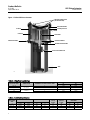
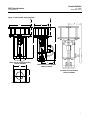
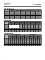
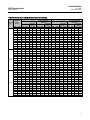
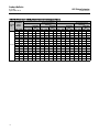
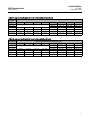
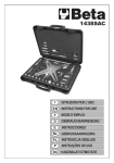
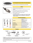
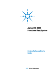
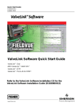
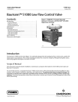
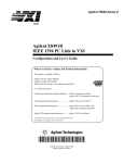
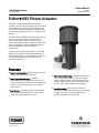
Product Bulletin 685 Piston Actuator 61.2:685 September 2014 D103625X012 Fisherr 685 Piston Actuator The 685 is a double-acting piston actuator that provides accurate, high thrust output for short to long travel applications. This actuator is designed for use with a variety of medium to large Fisher sliding-stem control valves including the easye™, FB, TBX, HP, EH, and 461. The 685 family is available in several configurations to cover a wide range of application requirements. Typical travels range from 25 to 610 mm (1 to 24 inches) and cylinder diameters range from 305 to 660 mm (12 to 26 inches). Thrust capabilities extend to 354 kN (79,000 lbf) and above with special constructions. The 685 can be used with the FIELDVUE™ DVC6200 digital valve controller for throttling applications, or with switching valves for onoff control. This actuator can also be fitted with volume boosters for fast stroking requirements. Features High Thrust Capability — Maximum thrusts of up to 354 kN (79,000 lbf) can be produced. Broad Application Coverage — Standard constructions offer travels of up to 610 mm (24 inches) and cylinder diameters of up to 660 mm (26 inches). Even larger constructions are available upon request. Low Friction — Low friction piston seals and either chrome plated or fluoropolymer coated cylinder bores reduce sliding friction and wear. www.Fisher.com X0922 Wide Temperature Range — Standard constructions offer a temperature range of -40 to 93_C (-40 to 200_F), however higher or lower temperatures are possible. Special constructions can operate as low as -54_C (65_F) and as high as 204_C (400_F). Manual Override — An optional side-mounted handwheel is capable of extending or retracting the actuator manually and can be engaged at any position from full open to full closed. Product Bulletin 685 Piston Actuator 61.2:685 September 2014 D103625X012 Table 1. Specifications Operating Pressure(1) Minimum: 2.7 bar (40psig) Construction Materials Maximum Allowable: 10.3 bar (150 psig) Consult your Emerson Process Management sales office for supply pressures under 2.7 bar (40 psig) PART MATERIAL Yoke ASTM A36 (steel) Piston ASTM A36 (steel) Cylinder 305 to 559 mm (12 to 22 inch) cylinder: 1026 DOM (steel) with chrome-plated bore 610 to 660 mm (24 to 26 inch) cylinder: ASTM A516 Grade 70 (steel) with fluoropolymer coated bore Travel(2) 25 mm (1 inch) through 610 mm (24 inch) See table 4 Thrust Capabilities See table 5 Piston Diameter and Area(2) Available in 51 mm (2 inch) increments between 305 mm (12 inch) and 660 mm (26 inch) See table 4 For additional sizes, contact your Emerson Process Management sales office. Operative Temperature Limits Standard: 40 to 93_C (40 to 200_F) Low Temperature: 54 to 93_C (65 to 200_F)(3) High Temperature: 29 to 204_C (20 to 400_F)(3) Yoke Boss and Valve Stem Diameter J 127 mm (5H inch) yoke boss with 32 mm (1-1/4 inch) stem J 178 mm (7 inch) yoke boss with 51 mm (2 inch) stem Pressure Connections Standard: 3/4 NPT Optional: 1 and 11/4 NPT See figure 2 and table 6 ASTM A36 (steel) Tie Bolt ASTM A311 1045, Class B (steel) Piston Rod S31603 (316L stainless steel) Stem Connector ASTM A36 (steel) Weights See tables 11 and 12 Lifting Point Load Ratings See table 2 Options Mechanical Handwheel, J Pneumatic fail mode via Fisher 377 trip valve, J Volume Boosters, J Fisher Optimized Digital Valve (ODV) Package J Dimensions See figure 3 and tables 7, 8, 9, and 10 Certifications J J Instrument Mounting Mounting kits are available for use with the FIELDVUE DVC6200 series positioner Upper/Lower Heads Pressure Equipment Directive (PED) 97/23/EC, ATEX Group II Category 2 Gas and Dust , Systematic Safety Integrity, SIL 3, J GOST-R (Russia), J GOST-K (Kazakhstan) J 1. The pressure/temperature limits in this bulletin and any other applicable standard or code should not be exceeded. 2. Consult factory for larger travels or cylinder diameters. The Fisher 585C family of actuators can be used for smaller travels or cylinder diameters. 3. Consult factory for applications requiring low or high temperature requirements. 2 685 Piston Actuator D103625X012 Product Bulletin 61.2:685 September 2014 Principle of Operation actuator cylinder or piston is removed for maintenance. 685 piston actuators utilize a pneumatically controlled piston that moves inside of a cylinder to generate thrust. A seal contained on the circumference of the piston provides a seal between the piston and the cylinder, preventing supply pressure leakage. Instrument Selection From an equilibrium state, the actuator operates by reacting to a force unbalance that is created by increasing supply pressure on one side of the piston, and decreasing it on the other. This moves the piston up or down, and results in a repositioning of the attached control valve. Travel can be adjusted using travel limits within a valve positioner, which limit the travel range of the actuator. The optional handwheel manual override does not have the ability to act as a hard travel stop. An optional handwheel manual override is capable of extending or retracting the actuator manually and can be engaged at any position from full open to full close. This override utilizes a worm gear assembly that is attached to the stem connector and not attached to the cylinder or piston rod. This enables the manual override to reposition the control valve even if the An excellent selection of sensitive and accurate instruments is available for 685 piston actuators. These include the FIELDVUE DVC6200 digital valve controller, as well trip valves and volume boosters. DVC6200 Digital Valve Controller FIELDVUE DVC6200 digital valve controllers are communicating, microprocessorbased currenttopneumatic instruments. In addition to the traditional function of converting a current signal to a pressure signal, DVC6200 digital valve controllers, using HARTr or FOUNDATION™ fieldbus communications protocol, give easy access to information critical to process operation. For additional information, refer to Fisher bulletin 62.1:DVC6200 (D103415X012) or 62.1:DVC6200f (D103399X012), available at www.FIELDVUE.com or from your Emerson Process Management sales office. 3 Product Bulletin 685 Piston Actuator 61.2:685 September 2014 D103625X012 Figure 1. Fisher 685 Piston Actuator PRESSURE CONNECTIONS (TOP AND BOTTOM) PISTON WEAR RING PISTON QUAD SEAL TIE RODS PISTON CYLINDER PISTON ROD MOUNTING BOSSES BEARING ASSEMBLY BEARING RETAINING RING VALVE STEM CONNECTOR YOKE X0923 Table 2. Lifting Point Load Ratings LIFTING ORIENTATION ACTUATOR SIZE 12 to 24 26 12 to 24 26 MAXIMUM LOAD NUMBER OF LIFTING POINTS USED kg lbs Actuator Centerline Horizontal 2 1540 3400 2 2860 6300 Actuator Centerline Vertical 2 3760 8300 2 6350 14000 Table 3. Handwheel Specification N lbs mm Inch 12 44482 10000 305 12 3.8 96 290 14 to 18 88964 20000 406 16 3.0 80 380 85 20 to 26 133447 30000 610 24 2.8 72 450 100 4 OUTPUT THRUST HANDWHEEL DIAMETER TURNS PER INCH OF TRAVEL MAXIMUM RIM FORCE REQUIRED N lbs TURNS PER mm OF TRAVEL ACTUATOR SIZE 65 Product Bulletin 685 Piston Actuator 61.2:685 September 2014 D103625X012 Table 4. Standard Constructions(1) ACTUATOR SIZE PISTON DIAMETER PISTON ROD AREA PISTON AREA VALVE STEM CONNECTOR SIZE YOKE BOSS DIAMETER Minimum Maximum VALVE TRAVEL mm (cm2 for Area) 12 305 16 730 32 or 51 127 or 178 >203 610 14 356 32 993 32 or 51 127 or 178 >203 610 16 406 32 1297 32 or 51 127 or 178 >203 610 18 457 32 1642 32 or 51 127 or 178 >203 610 20 508 46 2027 32 or 51 127 or 178 25 610 22 559 46 2452 32 or 51 127 or 178 25 610 24 610 62 2919 32 or 51 127 or 178 25 610 26 660 62 3425 32 or 51 127 or 178 25 610 Inches (inch2 for Area) 12 12 2.41 113 1 1/4 or 2 5H or 7 >8 24 14 14 4.91 154 1 1/4 or 2 5H or 7 >8 24 16 16 4.91 201 1 1/4 or 2 5H or 7 >8 24 18 18 4.91 254 1 1/4 or 2 5H or 7 >8 24 20 20 7.07 314 1 1/4 or 2 5H or 7 1 24 22 22 7.07 380 1 1/4 or 2 5H or 7 1 24 24 24 9.62 452 1 1/4 or 2 5H or 7 1 24 26 26 9.62 531 1 1/4 or 2 5H or 7 1 24 1. Consult your Emerson Process Management sales office for additional sizes. Table 5. Thrust THRUST AT SUPPLY PRESSURE, N (LBF)(1) ACTUATOR SIZE STROKE 12 30183 (6786) 40245 (9048) 50306 (11310) 10.3 barg (150 psig)(2) 75459 (16965) 14 41083 (9236) 54777 (12315) 68472 (15394) 102707 (23091) 16 53659 (12064) 71546 (16085) 89432 (20106) 134149 (30159) 18 67913 (15268) 90550 (20358) 113188 (25447) 169782 (38170) 83843 (18850) 111790 (25133) 139738 (31416) 209607 (47124) 22 101450 (22808) 135266 (30411) 169083 (38013) 253625 (57020) 24 120734 (27143) 160978 (36191) 201223 (45239) 301834 (67858) 26 141694 (31856) 188926 (42474) 236157 (53093) 354236 (79639) 12 29540 (6641) 39387 (8855) 49234 (11069) 73851 (16603) 14 39773 (8942) 53030 (11922) 66288 (14903) 99432 (22354) 16 52349 (11769) 69799 (15692) 87248 (19615) 130873 (29423) 66602 (14974) 88803 (19965) 111004 (24956) 166506 (37434) 81956 (18425) 109275 (24567) 136593 (30709) 204890 (46063) 22 99563 (22384) 132751 (29845) 165938 (37306) 248907 (55959) 24 118166 (26566) 157555 (35422) 196944 (44277) 295416 (66415) 26 139127 (31279) 185503 (41705) 231878 (52131) 347817 (78196) 20 18 20 Push Pull 4.1 barg (60 psig) 5.5 barg (80 psig) 6.9 barg (100 psig) 1. Consult your Emerson Process Management sales office for supply pressures below 40 psig. 2. Maximum available thrust. 5 Product Bulletin 685 Piston Actuator 61.2:685 September 2014 D103625X012 Figure 2. Position of Pressure Connections X NPT PORT Y NPT PORT Y NPT PORT X NPT PORT Z NPT PORT TOP VIEW OF ACTUATOR WITH ≤ 203 mm (8 INCHES) OF VALVE TRAVEL TOP VIEW OF ACTUATOR WITH >203 mm (8 INCHES) OF VALVE TRAVEL C NPT PORT D NPT PORT A NPT PORT B NPT PORT E1563 B NPT PORT TOP VIEW OF ACTUATOR WITH MANUAL OVERRIDE WITH ≤ 203 mm (8 INCHES) OF VALVE TRAVEL TOP VIEW OF ACTUATOR WITH MANUAL OVERRIDE WITH >203 mm (8 INCHES) OF VALVE TRAVEL Table 6. Supply Connections WITH MANUAL OVERRIDE No Yes TRAVEL ACTUATOR SIZE mm Inches 12 >203 >8 3/4 14 to 26 >203 >8 3/4, 1, or 1-1/4 20 to 26 ≤203 ≤8 3/4, 1, or 1-1/4 12 >203 >8 3/4 14 to 26 >203 >8 3/4, 1, or 1-1/4 20 to 26 ≤203 ≤8 3/4, 1, or 1-1/4 1. Refer to figure 2. 2. Quantity of 2 top and 2 bottom is available as standard for 3/4 NPT only. 6 SUPPLY CONNECTION Size, NPT(2) Quantity (Top/Bottom)(2) Location(1) 1/1 Z 2/2 X and Z 1/1 Z 2/2 Y and Z 1/1 Y 2/2 X and Y 1/1 B 2/2 B and C 1/1 B 2/2 B and D 1/1 A 2/2 A and B Product Bulletin 685 Piston Actuator 61.2:685 September 2014 D103625X012 Figure 3. Fisher Double-Acting Actuator AR AR H A A B B C C FRONT VIEW OF ACTUATOR WITHOUT MANUAL OVERRIDE E G FRONT VIEW OF ACTUATOR WITH MANUAL OVERRIDE LEFT VIEW OF ACTUATOR WITH MANUAL OVERRIDE F E1564 VIEW OF BOTTOM OF YOKE BOSS 7 Product Bulletin 685 Piston Actuator 61.2:685 September 2014 D103625X012 Table 7. Dimensions A, G, and H A ACTUATOR SIZE G H mm Inch mm Inch mm Inch 12 381 15.00 338 13.31 235 9.25 14 432 17.00 435 17.13 253 9.98 16 489 19.25 435 17.13 253 9.98 18 543 21.38 435 17.13 253 9.98 20 591 23.25 581 22.88 434 17.10 22 654 25.75 581 22.88 434 17.10 24 711 28.00 584 23.00 484 19.06 26 775 30.50 584 23.00 484 19.06 Table 8. Dimension B Dimension B for Maximum Valve Travel, mm (Inch) 305 mm (12.00 inch) mm Inch 406 mm (16.00 inch) mm Inch 508 mm (20.00 inch) mm Inch 610 mm (24.00 inch) mm Inch 12 432 17.00 533 21.00 635 25.00 737 29.00 14 445 17.50 546 21.50 648 25.50 749 29.50 16 445 17.50 546 21.50 648 25.50 749 29.50 18 445 17.50 546 21.50 648 25.50 749 29.50 ACTUATOR SIZE 102 mm (4 inch) mm Inch 203 mm (8 inch) mm Inch 20 259 10.20 361 14.20 462 18.20 564 22.20 665 26.20 767 30.20 22 259 10.20 361 14.20 462 18.20 564 22.20 665 26.20 767 30.20 24 265 10.45 367 14.45 469 18.45 570 22.45 672 26.45 773 30.45 26 265 10.45 367 14.45 469 18.45 570 22.45 672 26.45 773 30.45 Table 9. Dimensions E and F WITHOUT MANUAL OVERRIDE ACTUATOR SIZE 8 E 5H Yoke Boss WITH MANUAL OVERRIDE E F 7 Inch Yoke Boss 5H Yoke Boss 7 Inch Yoke Boss 5H Yoke Boss F 7 Inch Yoke Boss 5H Yoke Boss 7 Inch Yoke Boss mm Inch mm Inch mm Inch mm Inch mm Inch mm Inch mm Inch mm Inch 12 222 8.75 267 10.50 203 8.00 229 9.00 251 9.88 279 11.00 229 9.00 229 9.00 14 229 9.00 267 10.50 203 8.00 229 9.00 238 9.38 279 11.00 305 12.00 305 12.00 16 229 9.00 267 10.50 203 8.00 229 9.00 238 9.38 279 11.00 305 12.00 305 12.00 18 229 9.00 267 10.50 203 8.00 229 9.00 238 9.38 279 11.00 305 12.00 305 12.00 20 305 12.00 305 12.00 305 12.00 305 12.00 305 12.00 305 12.00 330 13.00 330 13.00 22 305 12.00 305 12.00 305 12.00 305 12.00 305 12.00 305 12.00 330 13.00 330 13.00 24 406 16.00 406 16.00 457 18.00 457 18.00 476 18.75 476 18.75 457 18.00 457 18.00 26 406 16.00 406 16.00 457 18.00 457 18.00 476 18.75 476 18.75 457 18.00 457 18.00 Product Bulletin 685 Piston Actuator 61.2:685 September 2014 D103625X012 Table 10. Dimensions C and AR (Actuator Removal Clearance) WITHOUT MANUAL OVERRIDE ACTUATOR SIZE 12 14, 16, and 18 20 and 22 MAXIMUM VALVE TRAVEL C WITH MANUAL OVERRIDE AR (Actuator Removal Clearance) 7 Inch Yoke 5H Yoke Boss Boss mm Inch mm Inch C AR (Actuator Removal Clearance) 7 Inch Yoke 5H Yoke Boss Boss mm Inch mm Inch mm Inch mm Inch 7 Inch Yoke Boss mm Inch mm Inch 7 Inch Yoke Boss mm Inch 267 10.50 1078 42.44 1078 42.44 381 15.00 381 15.00 1192 46.94 1192 46.94 381 15.00 381 15.00 279 11.00 1078 42.44 1078 42.44 318 12.50 318 12.50 1192 46.94 1230 48.44 318 12.50 356 14.00 305 12.00 1078 42.44 1078 42.44 305 12.00 305 12.00 1218 47.94 1230 48.44 330 13.00 343 13.50 368 14.50 1281 50.44 1281 50.44 381 15.00 381 15.00 1319 51.94 1395 54.94 305 12.00 381 15.00 381 15.00 1281 50.44 1281 50.44 318 12.50 318 12.50 1319 51.94 1434 56.44 241 9.50 356 14.00 406 16.00 1281 50.44 1281 50.44 305 12.00 305 12.00 1421 55.94 1434 56.44 330 13.00 343 13.50 470 18.50 1484 58.44 1484 58.44 381 15.00 381 15.00 1599 62.94 1599 62.94 381 15.00 381 15.00 483 19.00 1484 58.44 1484 58.44 318 12.50 318 12.50 1599 62.94 1637 64.44 318 12.50 356 14.00 508 20.00 1484 58.44 1484 58.44 305 12.00 305 12.00 1624 63.94 1637 64.44 330 13.00 343 13.50 572 22.50 1688 66.44 1688 66.44 381 15.00 381 15.00 1802 70.94 1802 70.94 381 15.00 381 15.00 584 23.00 1688 66.44 1688 66.44 318 12.50 318 12.50 1802 70.94 1840 72.44 318 12.50 356 14.00 610 24.00 1688 66.44 1688 66.44 305 12.00 305 12.00 1827 71.94 1840 72.44 330 13.00 343 13.50 267 10.50 1124 44.25 1124 44.25 381 15.00 381 15.00 1294 50.94 1294 50.94 381 15.00 381 15.00 279 11.00 1124 44.25 1124 44.25 318 12.50 318 12.50 1294 50.94 1332 52.44 318 12.50 356 14.00 305 12.00 1124 44.25 1124 44.25 305 12.00 305 12.00 1319 51.94 1332 52.44 330 13.00 343 13.50 368 14.50 1327 52.25 1327 52.25 381 15.00 381 15.00 1421 55.94 1497 58.94 305 12.00 381 15.00 381 15.00 1327 52.25 1327 52.25 318 12.50 318 12.50 1421 55.94 1535 60.44 241 9.50 356 14.00 406 16.00 1327 52.25 1327 52.25 305 12.00 305 12.00 1522 59.94 1535 60.44 330 13.00 343 13.50 470 18.50 1530 60.25 1530 60.25 381 15.00 381 15.00 1700 66.94 1700 66.94 381 15.00 381 15.00 483 19.00 1530 60.25 1530 60.25 318 12.50 318 12.50 1700 66.94 1738 68.44 318 12.50 356 14.00 508 20.00 1530 60.25 1530 60.25 305 12.00 305 12.00 1726 67.94 1738 68.44 330 13.00 343 13.50 572 22.50 1734 68.25 1734 68.25 381 15.00 381 15.00 1903 74.94 1903 74.94 381 15.00 381 15.00 584 23.00 1734 68.25 1734 68.25 318 12.50 318 12.50 1903 74.94 1942 76.44 318 12.50 356 14.00 610 24.00 1734 68.25 1734 68.25 305 12.00 305 12.00 1929 75.94 1942 76.44 330 13.00 343 13.50 102 4.00 754 29.69 786 30.94 334 13.13 365 14.38 937 36.88 949 37.38 381 15.00 394 15.50 152 6.00 941 37.06 967 38.06 343 13.50 368 14.50 1140 44.88 1102 43.38 406 16.00 368 14.50 203 8.00 941 37.06 1018 40.06 292 11.50 368 14.50 1140 44.88 1153 45.38 356 14.00 368 14.50 267 10.50 1183 46.56 1183 46.56 381 15.00 381 15.00 1318 51.88 1318 51.88 381 15.00 381 15.00 279 11.00 1183 46.56 1183 46.56 318 12.50 318 12.50 1318 51.88 1356 53.38 318 12.50 356 14.00 305 12.00 1183 46.56 1183 46.56 305 12.00 305 12.00 1343 52.88 1356 53.38 330 13.00 343 13.50 368 14.50 1386 54.56 1386 54.56 381 15.00 381 15.00 1445 56.88 1521 59.88 305 12.00 381 15.00 381 15.00 1386 54.56 1386 54.56 318 12.50 318 12.50 1445 56.88 1559 61.38 241 9.50 356 14.00 406 16.00 1386 54.56 1386 54.56 305 12.00 305 12.00 1546 60.88 1559 61.38 330 13.00 343 13.50 470 18.50 1589 62.56 1589 62.56 381 15.00 381 15.00 1724 67.88 1724 67.88 381 15.00 381 15.00 483 19.00 1589 62.56 1589 62.56 318 12.50 318 12.50 1724 67.88 1762 69.38 318 12.50 356 14.00 508 20.00 1589 62.56 1589 62.56 305 12.00 305 12.00 1750 68.88 1762 69.38 330 13.00 343 13.50 572 22.50 1792 70.56 1792 70.56 381 15.00 381 15.00 1927 75.88 1927 75.88 381 15.00 381 15.00 584 23.00 1792 70.56 1792 70.56 318 12.50 318 12.50 1927 75.88 1965 77.38 318 12.50 356 14.00 610 24.00 1792 70.56 1792 70.56 305 12.00 305 12.00 1953 76.88 1965 77.38 330 13.00 343 13.50 5H Yoke Boss 5H Yoke Boss -continued- 9 Product Bulletin 685 Piston Actuator 61.2:685 September 2014 D103625X012 Table 10. Dimensions C and AR (Actuator Removal Clearance) (continued) WITHOUT MANUAL OVERRIDE ACTUATOR SIZE 24 and 26 10 MAXIMUM VALVE TRAVEL C WITH MANUAL OVERRIDE AR (Actuator Removal Clearance) 7 Inch Yoke 5H Yoke Boss Boss mm Inch mm Inch C AR (Actuator Removal Clearance) 7 Inch Yoke 5H Yoke Boss Boss mm Inch mm Inch mm Inch mm Inch 7 Inch Yoke Boss mm Inch mm Inch 7 Inch Yoke Boss mm Inch 102 4.00 794 31.26 826 32.51 334 13.13 365 14.38 1000 39.38 1013 39.88 381 15.00 394 15.50 152 6.00 981 38.63 1007 39.63 343 13.50 368 14.50 1203 47.38 1165 45.88 406 16.00 368 14.50 203 8.00 981 38.63 1057 41.63 292 11.50 368 14.50 1203 47.38 1216 47.88 356 14.00 368 14.50 267 10.50 1223 48.13 1223 48.13 381 15.00 381 15.00 1381 54.38 1381 54.38 381 15.00 381 15.00 279 11.00 1223 48.13 1223 48.13 318 12.50 318 12.50 1381 54.38 1419 55.88 318 12.50 356 14.00 305 12.00 1223 48.13 1223 48.13 305 12.00 305 12.00 1407 55.38 1419 55.88 330 13.00 343 13.50 368 14.50 1426 56.13 1426 56.13 381 15.00 381 15.00 1508 59.38 1584 62.38 305 12.00 381 15.00 381 15.00 1426 56.13 1426 56.13 318 12.50 318 12.50 1508 59.38 1623 63.88 241 9.50 356 14.00 406 16.00 1426 56.13 1426 56.13 305 12.00 305 12.00 1610 63.38 1623 63.88 330 13.00 343 13.50 470 18.50 1629 64.13 1629 64.13 381 15.00 381 15.00 1788 70.38 1788 70.38 381 15.00 381 15.00 483 19.00 1629 64.13 1629 64.13 318 12.50 318 12.50 1788 70.38 1826 71.88 318 12.50 356 14.00 508 20.00 1629 64.13 1629 64.13 305 12.00 305 12.00 1813 71.38 1826 71.88 330 13.00 343 13.50 572 22.50 1832 72.13 1832 72.13 381 15.00 381 15.00 1991 78.38 1991 78.38 381 15.00 381 15.00 584 23.00 1832 72.13 1832 72.13 318 12.50 318 12.50 1991 78.38 2029 79.88 318 12.50 356 14.00 610 24.00 1832 72.13 1832 72.13 305 12.00 305 12.00 2016 79.38 2029 79.88 330 13.00 343 13.50 5H Yoke Boss 5H Yoke Boss Product Bulletin 685 Piston Actuator 61.2:685 September 2014 D103625X012 Table 11. Approximate Weights for Constructions without Handwheels MAXIMUM VALVE TRAVEL mm (inches) APPROXIMATE WEIGHT FOR ACTUATOR SIZE, kg (lbs) 12 14 16 18 102 (4.00) 203 (8.00) 20 22 24 26 402 (886) 475 (1048) 662 (1459) 761 (1677) 430 (947) 505 (1114) 702 (1548) 804 (1771) 305 (12.00) 157 (346) 245 (541) 292 (643) 337 (742) 457 (1008) 535 (1180) 743 (1637) 847 (1866) 406 (16.00) 168 (370) 262 (577) 311 (686) 358 (789) 485 (1069) 565 (1246) 783 (1726) 889 (1961) 508 (20.00) 179 (395) 278 (614) 331 (729) 379 (836) 512 (1129) 595 (1311) 823 (1815) 932 (2056) 610 (24.00) 190 (420) 295 (650) 350 (773) 401 (883) 540 (1190) 625 (1377) 864 (1904) 975 (2150) Table 12. Approximate Weights for Constructions with Handwheels MAXIMUM VALVE TRAVEL mm (inches) APPROXIMATE WEIGHT FOR ACTUATOR SIZE, kg (lbs) 12 14 16 18 102 (4.00) 203 (8.00) 20 22 24 26 591 (1304) 664 (1463) 834 (1838) 925 (2038) 622 (1372) 696 (1535) 873 (1924) 965 (2128) 305 (12.00) 226 (499) 363 (800) 292 (643) 454 (1000) 653 (1440) 729 (1607) 912 (2010) 1006 (2218) 406 (16.00) 239 (527) 380 (838) 311 (686) 474 (1046) 684 (1508) 762 (1679) 951 (2096) 1047 (2308) 508 (20.00) 252 (555) 397 (876) 331 (729) 495 (1092) 715 (1576) 794 (1751) 990 (2182) 1088 (2398) 610 (24.00) 264 (583) 415 (914) 350 (773) 516 (1138) 746 (1644) 827 (1823) 1029 (2268) 1129 (2488) 11 Product Bulletin 61.2:685 September 2014 685 Piston Actuator D103625X012 Neither Emerson, Emerson Process Management, nor any of their affiliated entities assumes responsibility for the selection, use or maintenance of any product. Responsibility for proper selection, use, and maintenance of any product remains solely with the purchaser and end user. Fisher, easy-e, and FIELDVUE are marks owned by one of the companies in the Emerson Process Management business unit of Emerson Electric Co. Emerson Process Management, Emerson, and the Emerson logo are trademarks and service marks of Emerson Electric Co. HART is a mark owned by the HART Communication Foundation. All other marks are the property of their respective owners. The contents of this publication are presented for informational purposes only, and while every effort has been made to ensure their accuracy, they are not to be construed as warranties or guarantees, express or implied, regarding the products or services described herein or their use or applicability. All sales are governed by our terms and conditions, which are available upon request. We reserve the right to modify or improve the designs or specifications of such products at any time without notice. Emerson Process Management Marshalltown, Iowa 50158 USA Sorocaba, 18087 Brazil Chatham, Kent ME4 4QZ UK Dubai, United Arab Emirates Singapore 128461 Singapore www.Fisher.com E 122013, 2014 Fisher Controls International LLC. All rights reserved.