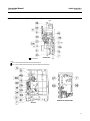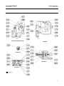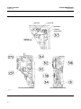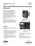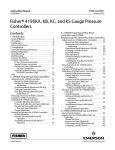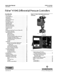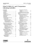
1
Instruction Manual
4194HS Controllers
D200157X012
October 2011
Fisherr 4194HS Differential Pressure Indicating
Controllers
Contents
Introduction . . . . . . . . . . . . . . . . . . . . . . . . . . . . . . . . . 2
Scope of Manual . . . . . . . . . . . . . . . . . . . . . . . . . . . . . 2
Description . . . . . . . . . . . . . . . . . . . . . . . . . . . . . . . . . 2
Specifications . . . . . . . . . . . . . . . . . . . . . . . . . . . . . . . 5
Educational Services . . . . . . . . . . . . . . . . . . . . . . . . . 5
Installation, Mounting, and Connections . . . . . . . . . . 5
Pipestand Mounting . . . . . . . . . . . . . . . . . . . . . . . . . 6
Pressure Connections . . . . . . . . . . . . . . . . . . . . . . . . 6
Process Pressure Connections . . . . . . . . . . . . . . . . . 7
Vent Connection . . . . . . . . . . . . . . . . . . . . . . . . . . . . 8
Supply Pressure . . . . . . . . . . . . . . . . . . . . . . . . . . . . . 9
Remote Set Point
(suffix letter M) Connection . . . . . . . . . . . . . . . . . 9
Controller Operation . . . . . . . . . . . . . . . . . . . . . . . . . . 9
Adjustments . . . . . . . . . . . . . . . . . . . . . . . . . . . . . . . 11
Remote Set Point (suffix letter M) . . . . . . . . . . 11
Manual Set Point . . . . . . . . . . . . . . . . . . . . . . . . 11
Proportional Band (Differential Gap) . . . . . . . 11
Changing Controller Action . . . . . . . . . . . . . . . 11
Switching The Auto/Manual Station
(suffix letter E) . . . . . . . . . . . . . . . . . . . . . . . 11
Prestartup Checks . . . . . . . . . . . . . . . . . . . . . . . . . . 12
Startup . . . . . . . . . . . . . . . . . . . . . . . . . . . . . . . . . . . 12
Calibration . . . . . . . . . . . . . . . . . . . . . . . . . . . . . . . . 12
Process Indicator Zero‐and‐Span
Adjustment . . . . . . . . . . . . . . . . . . . . . . . . . . 13
Remote Set Point Zero‐and‐Span
Adjustment (suffix letter M) . . . . . . . . . . . . 13
Setting Switching Points . . . . . . . . . . . . . . . . . 14
Direct‐Acting Controllers . . . . . . . . . . . . . . . 14
Reverse‐Acting Controllers . . . . . . . . . . . . . 15
Principle of Operation . . . . . . . . . . . . . . . . . . . . . . . . 16
Overall Operation . . . . . . . . . . . . . . . . . . . . . . . . . . . 16
Remote Set Point (suffix letter M) . . . . . . . . . . . . . 17
Auto/Manual Station (suffix letter E) . . . . . . . . . . . 17
Maintenance . . . . . . . . . . . . . . . . . . . . . . . . . . . . . . . . 18
Inspection and Maintenance . . . . . . . . . . . . . . . . . . 18
Troubleshooting . . . . . . . . . . . . . . . . . . . . . . . . 19
Changing Controller Action . . . . . . . . . . . . . . . 20
Replacing the Differential Pressure Unit . . . . . 21
Replacing Controller Parts . . . . . . . . . . . . . . . . 22
Process Pressure Scale . . . . . . . . . . . . . . . . . . 23
Relay . . . . . . . . . . . . . . . . . . . . . . . . . . . . . . . . . 23
Case and Cover . . . . . . . . . . . . . . . . . . . . . . . . 24
www.Fisher.com
Figure 1. Fisher 4194HS Differential Pressure
Controller
W5907
NAMEPLATE
W5908
Gauges . . . . . . . . . . . . . . . . . . . . . . . . . . . . . . .
Links . . . . . . . . . . . . . . . . . . . . . . . . . . . . . . . . .
Link Number 1 . . . . . . . . . . . . . . . . . . . . . . . .
Link Number 2 . . . . . . . . . . . . . . . . . . . . . . . .
Link Number 3 . . . . . . . . . . . . . . . . . . . . . . . .
Link Number 4 . . . . . . . . . . . . . . . . . . . . . . . .
Supply Tubing and Positive Feedback
Tubing Assemblies . . . . . . . . . . . . . . . . . . . .
25
25
25
26
27
28
28
Instruction Manual
4194HS Controllers
October 2011
D200157X012
Contents (continued)
Proportional Band Knob, Nozzle Pivot,
and Set Point Beam Assembly . . . . . . . . . . .
Flapper Flexure Pivot Assembly . . . . . . . . . . .
Positive Feedback Bellows . . . . . . . . . . . . . . .
Calibration After Controller Maintenance . . .
Process Zero‐and‐Span Adjustment . . . . . . .
Flapper Alignment . . . . . . . . . . . . . . . . . . . . .
Replacing Remote Set Point
(suffix letter M) Parts . . . . . . . . . . . . . . . . . .
Pivot Assembly A . . . . . . . . . . . . . . . . . . . . . . .
Pivot Assembly B . . . . . . . . . . . . . . . . . . . . . . .
Drive Flexure . . . . . . . . . . . . . . . . . . . . . . . . . .
Tubing . . . . . . . . . . . . . . . . . . . . . . . . . . . . . . .
Remote Set Point Capsular
Element Assembly . . . . . . . . . . . . . . . . . . . .
Link A . . . . . . . . . . . . . . . . . . . . . . . . . . . . . . .
Link B . . . . . . . . . . . . . . . . . . . . . . . . . . . . . . .
Pressure Control Block for
Remote Set Point . . . . . . . . . . . . . . . . . . . . .
Remote Set Point Maintenance Calibration . .
Remote Set Point Precalibration
Procedures . . . . . . . . . . . . . . . . . . . . . . . . . .
Setting Remote Set Point Travel Stops . . . . .
Aligning Remote Set Point Linkage . . . . . . . .
Remote Set Point Zero‐and‐Span
Adjustment . . . . . . . . . . . . . . . . . . . . . . . . . .
29
34
36
38
38
38
40
40
41
41
41
42
42
42
43
43
43
44
44
44
Remote Set Point Linearity Adjustment . . . .
Auto/Manual Station (suffix letter E) . . . . . . . . . . .
Replacing the Auto/Manual Station . . . . . . .
Disassembly . . . . . . . . . . . . . . . . . . . . . . . . .
Assembly . . . . . . . . . . . . . . . . . . . . . . . . . . . .
Replacing the Auto/Manual Station Switch
Body Assembly, Lever O‐Ring, Switch
Body O‐Ring, and the Tubing Assembly . . .
Disassembly . . . . . . . . . . . . . . . . . . . . . . . .
Assembly . . . . . . . . . . . . . . . . . . . . . . . . . . .
Replacing Auto/Manual Station
Loader Range Spring, Diaphragm
Assembly, Ball Seat, Tubing, and Ball . . . . .
Disassembly . . . . . . . . . . . . . . . . . . . . . . .
Assembly . . . . . . . . . . . . . . . . . . . . . . . . . .
Replacing the Auto/Manual Station Loader
Valve Plug and Valve Plug Spring . . . . . . . .
Parts . . . . . . . . . . . . . . . . . . . . . . . . . . . . . . . . . . . . . . .
Parts Ordering . . . . . . . . . . . . . . . . . . . . . . . . . . . . .
Parts Kits . . . . . . . . . . . . . . . . . . . . . . . . . . . . . . . . . .
Controller Parts . . . . . . . . . . . . . . . . . . . . . . . . . . . .
Process and Set Point Indicator Assembly . . . . . . .
Remote Set Point Assembly . . . . . . . . . . . . . . . . . .
Indicator Assembly . . . . . . . . . . . . . . . . . . . . . . . . .
Auto/Manual Station (suffix letter E) . . . . . . . . . . .
Controller Mounting Parts . . . . . . . . . . . . . . . . . . . .
Fittings . . . . . . . . . . . . . . . . . . . . . . . . . . . . . . . .
45
45
45
46
46
46
46
47
48
48
48
49
49
49
49
50
52
52
52
53
53
53
Introduction
Scope of Manual
This instruction manual provides installation, operating, calibration, maintenance, and parts ordering information for
the 4194HS (high static pressure) differential pressure indicating controllers.
The type number of the controller is on the nameplate. Refer to figure 1 for the location of the nameplate.
Configurations of the controller are indicated by letter suffixes in the type number that correspond to the mode and
option designated in table 1. Refer to table 1 for definition of each 4194HS type number.
Description
The controllers described in this manual provide differential gap control with options as shown in table 1. The
controller shows process differential pressure and set point on an easy‐to‐read process scale. The controller output is a
pneumatic signal that operates a final control element.
Table 1. Available Configurations
Controller(1)
Internal Auto/Manual Station (Suffix Letter E)
4194HS
4194HSE
4194HSM
4194HSME
1. Reverse‐acting constructions are designated by an R suffix in the type number.
2
Remote Set Point (Suffix Letter M)
X
X
X
X
Instruction Manual
4194HS Controllers
D200157X012
October 2011
Table 2. Specifications
Controller Adjustments
Available Configurations
See table 1
Differential Gap Control: 1 to 100% of process scale
range
Set Point: Continuously adjustable from 0 to 100% of
the scale range
Input Signal (Sensing Element Range)
Lower and Upper Range Limits: See tables 3 and 4
Maximum Allowable Operating Limits: See tables 3
and 4
Steady‐State Air Consumption(3,4)
0 to 1.4 Bar (0 to 20 Psig) Output: 0.1 normal m3/h
(3.5 scfh)
0 to 2.4 Bar (0 to 35 Psig) Output: 0.14 normal m3/h
(5.0 scfh)
Output Signal
Differential Gap Range: 0 and 1.4 bar (0 and 20 psig)
or 0 and 2.4 bar (0 and 35 psig)
Action: Field-reversible between direct (increasing
differential pressure increases output pressure) or
reverse (increasing differential pressure decreases
output pressure)
Delivery Capacity(4)
0 to 1.4 Bar (0 to 20 Psig) Output: 5.6 normal m3/h
(210 scfh)
0 to 2.4 Bar (0 to 35 Psig) Output: 9.9 normal m3/h
(370 scfh)
Process Scale
Standard scale is matched to the range of the sensing
element. Optional scales available(1).
Exhaust Capacity(4)
0 to 1.4 Bar (0 to 20 Psig) Output: 4.6 normal m3/h
(170 scfh)
0 to 2.4 Bar (0 to 35 Psig) Output: 7.0 normal m3/h
(260 scfh)
Process Connections
Standard: 1/4 NPT internal stainless steel (all input
ranges)
Optional: 1/2 NPT internal stainless steel
Operative Ambient Temperature Limits(2,5)
Supply and Output Connections
-40 to 70°C (-40 to 160°F)
1/4 NPT internal
Housing
Supply Pressure Requirements(2)
Designed to NEMA 3 (weatherproof) and IEC 529 IP54
specifications
See table 4
Supply Pressure Medium
Hazardous Area Classification
Air or natural gas
Complies with the requirements of ATEX Group II
Category 2 Gas and Dust
Air: Supply pressure must be clean, dry air that meets
the requirements of ISA Standard 7.0.01. A maximum
40 micrometer particle size in the air system is
acceptable. Further filtration down to 5 micrometer
particle size is recommended. Lubricant content is
not to exceed 1 ppm weight (w/w) or volume (v/v)
basis. Condensation in the air supply should be
minimized
Mounting
Controller is mounted on a pipestand. See figure 2.
Natural Gas: Natural gas must be clean, dry, oil‐free,
and noncorrosive. H2S content should not exceed 20
ppm.
Approximate Weight
Controller: 4.5 kg (10 lb) without the differential
pressure unit
Remote Set Point Pressure Ranges(2)
Differential Pressure Unit: 21.5 kg (47 lb)
Total Weight: 26 kg (57 lb) controller with a BartonR
199 differential pressure unit.
0.2 to 1.0 bar (3 to 15 psig) or 0.4 to 2.0 bar
(6 to 30 psig)
– Continued –
3
Instruction Manual
4194HS Controllers
October 2011
D200157X012
Table 2. Specifications (continued)
Declaration of SEP
with Sound Engineering Practice (SEP) and cannot
bear the CE marking related to PED compliance.
Fisher Controls International LLC declares this
product to be in compliance with Article 3 paragraph
3 of the Pressure Equipment Directive (PED) 97 / 23 /
EC. It was designed and manufactured in accordance
However, the product may bear the CE marking to
indicate compliance with other applicable European
Community Directives.
NOTE: Specialized instrument terms are defined in ANSI/ISA Standard 51.1 - Process Instrument Terminology.
1. Consult your Emerson Process Management sales office for additional information.
2. The pressure/temperature limits in this document, and any applicable standard or code limitation should not be exceeded
3. With Barton 199 differential pressure unit.
4. Normal m3/hr: normal cubic meters per hour (m3/hr, 0°C and 1.01.325 bar). Scfh: standard cubic feet per hour (ft3/hr, 60°F and 14.7 psia).
5. Also for transportation and storage limits..
Table 3. Process Sensor (Barton 199 Differential Pressure Unit) Range and Pressure Ratings
SAFE WORKING PRESSURE(3)
DIFFERENTIAL PRESSURE RANGE(1,2)
Psig (bar)
Inches w.c. (mbar)
0 to 15 (0 to 1)
0 to 30 (0 to 2)
0 to 40 (0 to 2.8)
0 to 50 (0 to 3.4)
0 to 60 (0 to 4)
0 to 75 (0 to 5)
0 to 15 (0 to 1)
0 to 30 (0 to 2)
0 to 40 (0 to 2.8)
0 to 50 (0 to 3.4)
0 to 60 (0 to 4)
0 to 75 (0 to 5)
0 to 15 (0 to 1)
0 to 30 (0 to 2)
0 to 40 (0 to 2.8)
0 to 50 (0 to 3.4)
0 to 60 (0 to 4)
0 to 75 (0 to 5)
0 to 20 (0 to 50)
0 to 25 (0 to 62)
0 to 50 (0 to 124)
0 to 75 (0 to 186)
0 to 100 (0 to 248)
0 to 20 (0 to 50)
0 to 25 (0 to 62)
0 to 50 (0 to 124)
0 to 75 (0 to 186)
0 to 100 (0 to 248)
0 to 20 (0 to 50)
0 to 25 (0 to 62)
0 to 50 (0 to 124)
0 to 75 (0 to 186)
0 to 100 (0 to 248)
HOUSING MATERIAL(2)
Bar
Psig
68.9
1000
Stainless steel
172
2500
Steel
414
6000
Steel
68.9
1000
Stainless steel
172
2500
Steel
414
6000
Steel
1. Differential pressure ranges are in English units of measurement; metric equivalents are shown here for reference only. Consult your Emerson Process Management ales office for special
differential pressure ranges.
2. For other ranges and materials, contact your Emerson Process Management sales office.
3. The Barton 199 differential pressure unit may be pressured to this value (after reaching the travel stop at the upper range limit) without permanent zero shift or structural damage to
controller components.
Table 4. Supply Pressure Data
Normal Operating Supply
Pressure(1)
Maximum Pressure Limit(2)
0 & 1.4
1.4
3.4
0 & 2.4
2.4
3.4
0 & 20
20
50
0 & 35
35
50
Output Signal Range
bar
psig
1. If this pressure is exceeded, control stability may be impaired.
2. If this pressure is exceeded, damage to the controller may result.
4
Instruction Manual
4194HS Controllers
D200157X012
October 2011
Do not install, operate, or maintain a 4194HS differential pressure indicating controller without being fully trained and
qualified in valve, actuator and accessory installation, operation and maintenance. To avoid personal injury or property
damage it is important to carefully read, understand, and follow all of the contents of this manual, including all safety
cautions and warnings. If you have any questions about these instructions, contact your Emerson Process
Management sales office before proceeding.
Specifications
Specifications for the 4194HS controllers are listed in table 2.
WARNING
This product is intended for a specific range of pressure, temperatures and other application specifications. Applying
different pressure, temperature and other service conditions could result in malfunction of the product, property damage
or personal injury.
Educational Services
For information on available courses for 4194HS controllers, as well as a variety of other products, contact:
Emerson Process Management
Educational Services, Registration
P.O. Box 190; 301 S. 1st Ave.
Marshalltown, IA 50158-2823
Phone: 800-338-8158 or
Phone: 641-754-3771
FAX: 641-754-3431
e‐mail: [email protected]
Installation, Mounting, and Connections
WARNING
To avoid personal injury or property damage from sudden release of process pressure:
D Always wear protective clothing, gloves, and eyewear when performing any installation operations to avoid personal
injury.
D Personal injury or property damage may result from fire or explosion if natural gas is used as the supply medium and
preventative measures are not taken. Preventative measures may include, but are not limited to, one or more of the
following: Remote venting of the unit, re‐evaluating the hazardous area classification, ensuring adequate ventilation,
and the removal of any ignition sources. For information on remote venting of this controller, refer to page 8.
D Check with your process or safety engineer for any additional measures that must be taken to protect against process
media.
D If installing into an existing application, also refer to the WARNING at the beginning of the Maintenance section in this
instruction manual.
5
Instruction Manual
4194HS Controllers
October 2011
D200157X012
Pipestand Mounting
A 4194HS controller mounts on a pipestand and must be installed with the vent opening facing down. The coupling is
secured to the pipestand by three set screws as shown in figure 2.
Figure 2. Right Side View of Controller
BARTON 199
DIFFERENTIAL
PRESSURE UNIT
1/2 NPT PRESSURE
CONNECTION
1
1/4 NPT PRESSURE
CONNECTION
1
PIPESTAND MOUNTING
BRACKET
SET SCREW
(3 REQ'D)
PIPESTAND
NOTE:
1 LOW PRESSURE CONNECTION ON A BARTON 199
DIFFERENTIAL PRESSURE UNIT.
W3635-1
Pressure Connections
WARNING
To avoid personal injury or property damage resulting from the sudden release of pressure, do not install any system
component, including the differential pressure unit, where service conditions could exceed the limits given in this manual
or on the appropriate nameplates. Use pressure‐relieving devices as required by government or accepted industry codes
and good engineering practices.
Refer to figures 2 and 3 for the location of all input and output connections for the controller and differential pressure
unit. Also, refer to the differential pressure unit instruction manual for specific information about connections and
piping.
6
Instruction Manual
4194HS Controllers
D200157X012
October 2011
Figure 3. Connections
1/4 NPT REMOTE
SET POINT CONNECTION
REMOTE SET POINT
CONNECTION
1
1/2 NPT
TOP VIEW
1/4 NPT
OPTIONAL
EXTERNAL
FEEDBACK
CONNECTION
1/4 NPT VENT
1/4 NPT
1
SUPPLY PRESSURE
CONTROLLER
OUTPUT PRESSURE
1/4 NPT 2 HOLES
LEFT SIDE VIEW
FRONT VIEW
BOTTOM VIEW
NOTE:
1 HIGH PRESSURE CONNECTION ON A BARTON 199
DIFFERENTIAL PRESSURE UNIT
18A5903‐B
A3000-1
Supply, output, vent, and remote set point connections are 1/4 NPT. Use 1/4‐ or 3/8‐inch pipe or tubing for supply,
output, vent, and remote set point piping.
Process pressure connections are 1/4 or 1/2 NPT (optional). When installing process piping from the differential
pressure sensing unit in the process pipeline to the differential pressure unit attached to the controller, follow
accepted engineering, installation, and safety practices to insure the safe and accurate transmission of the process
differential pressure to the differential pressure unit. Install shutoff valves, vents, drains, or seal systems as required by
accepted practices.
Process Pressure Connections
Process pressures are piped to the connections on the ends of the differential pressure unit (figure 4).
Refer to the differential pressure unit instruction manual for the high and low pressure connections.
When installing process piping, follow accepted practices to ensure accurate transmission of the process pressures to
the differential pressure unit.
Install a three‐valve bypass, shutoff valves, vents, drains, or seal systems as needed in the process pressure lines.
If the instrument is located such that the adjacent process pressure lines will be approximately horizontal, the lines
should slope downward to the instrument for liquid‐filled lines and upward toward the instrument for gas‐filled lines.
This will minimize the possibility of air becoming trapped in the sensor with liquid‐filled lines or of condensate
becoming trapped with gas‐filled lines. The recommended slope is 83 millimeters per meter (1 inch per foot).
7
Instruction Manual
4194HS Controllers
October 2011
D200157X012
Figure 4. Simplified Control Loop Diagram
2
LOW
PRESSURE
CONNECTIONS
SUPPLY
PRESSURE
LOW PRESSURE
PIPING
HIGH PRESSURE CONNECTIONS
OUTPUT
SIGNAL
HIGH PRESSURE PIPING
1
ORIFICE PLATE
NOTE:
1 TO ALLOW A REAR VIEW OF THE CONTROLLER/ DIFFERENTIAL
PRESSURE UNIT, THE SCHEMATIC SHOWS PROCESS FLOW FROM RIGHT TO LEFT.
2 SEE FIGURE 2 FOR LOW PRESSURE CONNECTIONS.
W5910
Vent Connection
WARNING
If a flammable gas is to be used as the supply pressure medium and the controller is in an enclosed area, personal injury or
property damage could result from fire or explosion of accumulated gas. The controller assembly does not form a gas‐tight
seal and a remote vent line is recommended. However, a remote vent line cannot be relied upon to remove all hazardous
gas. Leaks may still occur. Provide adequate ventilation and necessary safety measures. Vent line piping should comply
with local and regional codes and should be as short as possible with adequate inside diameter and few bends to reduce
case pressure buildup.
CAUTION
When installing a remote vent pipe, take care not to over‐tighten the pipe fitting in the vent connection. Excessive torque
will damage the threads in the connection.
If a remote vent is required, the vent line must be as short as possible with a minimum number of bends and elbows.
Vent line piping should have a minimum inside diameter of 19 mm (3/4 inches) for runs up to 6.1 m (20 feet) and a
minimum inside diameter of 25 mm (1 inch) for runs from 6.1 to 30.5 m (20 to 100 feet).
8
Instruction Manual
D200157X012
4194HS Controllers
October 2011
If a remote vent is not required, the vent opening (figure 3) must be protected against the entrance of any foreign
material that could plug it. Check the vent periodically to be certain it is not plugged.
Supply Pressure
WARNING
Personal injury or property damage may occur from an uncontrolled process if the supply medium is not clean, dry, oil‐free
air or a non‐corrosive gas. While use and regular maintenance of a filter that removes particles larger than 40 micrometers
in diameter will suffice in most applications, check with a Emerson Process Management field office and industry
instrument air quality standards for use with corrosive gas or if you are unsure about the proper amount or method of air
filtration or filter maintenance.
Supply pressure must be clean, dry air or noncorrosive gas that meets the requirements of ISA Standard 7.0.01. A
maximum 40 micrometer particle size in the air system is acceptable. Further filtration down to 5 micrometer particle
size is recommended. Lubricant content is not to exceed 1 ppm weight (w/w) or volume (v/v) basis. Condensation in
the air supply should be minimized. Alternatively, natural gas may be used as the supply pressure medium. Gas must
be clean, dry, oil‐free, and noncorrosive. H2S content should not exceed 20 ppm.
Use a suitable supply pressure regulator to reduce the supply pressure source to 1.4 bar (20 psig) for an output signal
range of 0 and 1.4 bar (0 and 20 psig) and to 2.4 bar (35 psig) for an output signal range of 0 and 2.4 bar (0 and 35
psig).
Remote Set Point (suffix letter M) Connection
If the controller has the remote set point option, connect the remote set point pressure to the top of the controller
case at the location shown in figure 3. Use clean, dry air or noncorrosive gas. If pressure is supplied to the remote set
point connection with a regulator, a small bleed orifice should be placed between the regulator and remote set point
connection to prevent pressure variations due to regulator lock‐up.
Controller Operation
Note
Some of the following procedures require that the proportional band knob be adjusted to between DIRECT and REVERSE. If this is
done, it will be necessary to set the proportional band knob to 400 (direct or reverse action) before replacing the proportional
band indicator cover.
This section includes descriptions of adjustments and procedures for prestartup and startup. Location of adjustments
is shown in figures 5 and 6.
To better understand the adjustments and overall operation of the controller, refer to the Principle of Operation
section which appears later in this manual. Also, refer to the schematic diagrams, figures 8 and 9.
9
Instruction Manual
4194HS Controllers
October 2011
D200157X012
Figure 5. Location of Controller Parts and Adjustments
SET POINT 1
ADJUSTMENT
PROCESS
INDICATOR
DRIVE ARM
LOCKING SCREW
PROPORTIONAL
BAND INDICATOR
COVER
PIVOT BRACKET
DRIVE ARM
PROPORTIONAL
BAND ADJUSTMENT
CONNECTING LINK 1
ZERO
ADJUSTMENT
PROCESS
SPAN
ADJUSTMENT
OUTPUT
PRESSURE
GAUGE
ZERO ADJUSTMENT
LOCKING SCREW
REMOTE SET POINT
SPAN ADJUSTMENT
35A7374‐B
SPAN ADJUSTMENT
SUPPLY PRESSURE GAUGE
SIDE VIEW OF SET POINT / PROCESS
INDICATOR ASSEMBLY
NOTE:
1 ON CONTROLLERS EQUIPPED WITH REMOTE SET POINT
OPTION, THIS IS THE REMOTE SET POINT INDICATOR.
W3688‐1
FRONT VIEW
Figure 6. Parts and Adjustments, Remote Set Point Option
GUIDE
FLEXURE
MOUNTING
SCREW
LINK A
PIVOT
ASSEMBLY A
DRIVE FLEXURE
ADJUSTMENT
SCREW
LINK B
LOWER TRAVEL
STOP
UPPER TRAVEL
STOP
LINEARITY
ADJUSTMENT
TIE BAR
PIVOT ASSEMBLY B
MOUNTING
SCREW
CAPSULES
REMOTE SET POINT ZERO ADJUSTMENT SCREW
ZERO ADJUSTMENT LOCKING SCREW
36A9751‐C
B1668‐4
10
FRONT VIEW
SIDE VIEW
Instruction Manual
D200157X012
4194HS Controllers
October 2011
Adjustments
Remote Set Point (suffix letter M)
CAUTION
Do not move the set point adjustment manually on controllers with remote set point. Moving the set point adjustment
could damage the controller.
If the controller is equipped with the remote set point option, vary the remote set point pressure to change the set
point. Increase the pressure to increase the set point and decrease the pressure to decrease the set point.
Manual Set Point
The set point adjustment changes the upper or lower switching point depending on controller action. To adjust the set
point, open the controller cover and move the set point adjustment indicator until the desired value on the process
pressure scale is below the line on the set point indicator. Move the adjustment to the right to increase the set point
and to the left to decrease it.
Changing the set point adjustment does not affect the differential gap setting.
Proportional Band (Differential Gap)
The proportional band knob adjusts the width of the gap between switching points. Rotate the proportional band
knob until the desired value is opposite the line on the proportional band indicator cover.
Changing Controller Action
Controller action is switchable from direct to reverse or vice versa by simply loosening the screws on the proportional
band indicator cover and moving the cover out so the proportional band knob can be rotated to the desired action.
The white portion of the adjustment enables direct controller action; the black portion enables reverse controller
action.
Switching The Auto/Manual Station (suffix letter E)
CAUTION
Switching the controller between automatic and manual mode without balancing can disturb the process and cause
controller cycling.
Refer to figure 28 if the controller has the auto/manual option.
To switch from automatic to manual mode, you must balance the manual output with the controller output. Two
balance methods are available to equalize the manual output with the controller output.
11
4194HS Controllers
October 2011
Instruction Manual
D200157X012
To switch from automatic to manual mode, carefully adjust the loader knob until the metal ball inside the plastic tube
moves into the switching zone. Then move the automatic/manual switch to MANUAL. Turn the loader knob clockwise
to increase the controller output or counterclockwise to decrease it.
To switch from manual to automatic mode, adjust the set point manually or with remote set point pressure to move
the ball into the switching zone. Turn the switch to AUTOMATIC and adjust the set point manually or with remote set
point pressure to control the output.
When the automatic/manual switch is in AUTOMATIC, adjusting the loader knob has no effect on the controller
output. When the automatic/manual switch is in MANUAL, changing the set point adjustment has no effect on the
controller output.
Prestartup Checks
When performing the checks, open process loop conditions must exist. Refer to figure 5 for location of adjustments.
Note
If the controller has the auto/manual option (suffix letter E), be sure the controller is in the automatic mode before performing
prestartup checks.
1. Connect supply pressure to the supply pressure regulator and be sure it is delivering the proper supply pressure to
the controller. Provide a means of measuring the controller output pressure.
2. For controllers with remote set point (suffix letter M), connect regulated pressure of 0.2 to 1.0 bar (3 to 15 psig)
or 0.4 to 2.1 bar (6 to 30 psig) to the remote set point connection at the top of the controller case.
3. Loosen two screws (key 6), lift off the proportional band indicator cover (key 36), and set the proportional band
knob between DIRECT and REVERSE.
4. The process indicator should indicate the process differential pressure. For example, with the process differential
pressure at 50 percent of the input span, the process pointer should be at 50$1.0 percent of its span. Slight
adjustment of the indicator zero screw might be necessary. See figure 5 for zero adjustment and locking screw
location.
5. If desired, the accuracy can be verified at other points on the scale. If the indicator is out of calibration, refer to the
process zero‐and‐span adjustment portion of the calibration procedure.
6. Install the proportional band indicator cover (key 36) and tighten two screws (key 6).
Startup
Set the controller switching point as described in the calibration procedures.
If manual control valves are being used to bypass the control valve package (valve, actuator, positioner, controller),
slowly open the upstream and downstream manual control valves in the pipeline and close the manual bypass valve.
Calibration
Note
Some of the following procedures require that the proportional band knob be adjusted to between DIRECT and REVERSE. If this is
done, it will be necessary to set the proportional band knob to 400 (direct or reverse action) before replacing the proportional
band indicator cover.
12
Instruction Manual
4194HS Controllers
D200157X012
October 2011
Note
If the controller has the auto/manual option, be sure the controller is in the automatic mode before performing calibration
procedures.
If the prestartup checks revealed faulty adjustment of the process indicator, perform the calibration procedures.
These procedures are valid for either shop or field calibration, if open process loop conditions exist.
Process Indicator Zero‐and‐Span Adjustment
Note
Any change in process pointer span will require readjustment of the process pointer zero adjustment screw.
Refer to figure 5 for location of adjustments.
1. Loosen two screws (key 6) and lift off the proportional band indicator cover (key 36).
2. Set the proportional band between DIRECT and REVERSE.
3. Adjust the process differential pressure to the low limit of the input range.
4. Adjust the process indicator to the lowest limit of the input scale by loosening the zero adjustment locking screw
and turning the zero adjustment screw.
5. Adjust the process differential pressure to the upper limit of the input span. Note whether the pointer indication is
above or below the upper limit of the process scale.
6. Adjust the span screw as follows: Clockwise to increase span for a low indication; counterclockwise to decrease span
for a high indication. Adjust the span screw to correct one‐half the error.
7. Repeat steps 3 through 6 until the error is eliminated.
8. Install the proportional band indicator cover(key 36) and tighten two screws (key 6).
Remote Set Point Zero‐and‐Span Adjustment (suffix letter M)
Note
Any adjustment of the pointer span adjustment screw will require readjustment of the pointer zero adjustment screw.
Refer to figures 5 and 6 for location of adjustments.
1. Loosen two screws (key 6) and lift off the proportional band indicator cover (key 36).
2. Set the proportional band between DIRECT and REVERSE.
3. Adjust the set point pressure to the low limit of the input range.
4. Adjust the set point indicator to the lowest limit of the input scale by loosening the zero adjustment locking screw
and turning the zero adjustment screw.
13
Instruction Manual
4194HS Controllers
October 2011
D200157X012
5. Adjust the set point pressure to the upper limit of the input span. Note whether the pointer indication is above or
below the upper limit of the process scale.
6. Adjust the span screw as follows: Clockwise to increase span for a low indication; counterclockwise to decrease span
for a high indication. Adjust the span screw to correct one‐half the error.
7. Repeat steps 3 through 6 until the error is eliminated.
8. Install the proportional band indicator cover (key 36) and tighten two screws (key 36).
Setting Switching Points
Direct‐Acting Controllers
The controller output signal will switch from zero pressure to full supply pressure when increasing process differential
pressure passes the upper switching point.
The controller output signal will not return to zero pressure until decreasing process differential pressure passes the
lower switching point. When adjusting the controller as described in the following steps, keep in mind that:
D Changing the set point adjustment will move both switching points equally in the direction of adjustment.
D Changing the proportional band adjustment will widen or narrow the differential gap between the two switching
points by moving the position of the lower switching point.
Figure 7 shows the relationship between the percent of sensor range between switching points and the proportional
band setting on the controller. The following example illustrates how to use figure 7.
PROPORTIONAL BAND SETTING
Figure 7. Curve for Determining Proportional Band Setting
A2853-1 / IL
% SENSOR RANGE BETWEEN SWITCHING POINTS
Example: The sensing element has a range of 30 psi. The lower switching point is to be set at 10 psi and the upper
switching point is to be set at 25 psi.
Proceed as follows:
D Divide the differential gap (the difference between the upper and lower switching points) by the sensing element
range. Multiply the result by 100 as shown in the following equation:
DifferentialGap
SensingElementRange
14
100 +
15psi
30psi
100 + 50%
Instruction Manual
4194HS Controllers
D200157X012
October 2011
D Locate the 50 percent line on figure 7. Move along this line until you intersect the curve. Read the proportional
band setting on the left hand axis. For this example, the setting is approximately 35 percent.
1. Using the curve in figure 7, determine the correct proportional band setting for the desired gap (expressed as a
percent of the input span) between the switching points.
2. Set the proportional band knob to the desired setting determined in step 1.
3. Adjust the set point to the desired upper switching point.
4. Increase the process differential pressure until the controller output signal switches from zero pressure to full
supply pressure.
5. Decrease the process differential pressure to the desired switching point at which the controller output signal
switches from full supply pressure to zero pressure.
6. Narrow or widen the proportional band slowly until the output signal switches from full supply pressure to zero
pressure.
7. Repeat steps 4 through 6 until the controller output switches at the desired points.
8. Observe the process pointer when the output switches at the upper switching point. The process pointer indication
should be within "2 percent of the set point indication.
Reverse‐Acting Controllers
The controller output signal will switch from zero pressure to full supply pressure when decreasing process differential
pressure passes the lower switching point.
The controller output signal will not return to zero pressure until increasing process differential pressure passes the
upper switching point. When adjusting the controller as described in the following steps, keep in mind that:
D Changing the set point adjustment will move both switching points equally in the direction of adjustment.
D Changing the proportional band adjustment will widen or narrow the differential gap between the two switching
points by moving the position of the upper switching point.
Figure 7 shows the relationship between the percent of sensor range between switching points and the proportional
band setting on the controller. The following example illustrates how to use figure 7.
Example: The sensing element has a range of 30 psi. The lower switching point is to be set at 10 psi and the upper
switching point is to be set at 25 psi.
Proceed as follows:
D Divide the differential gap (the difference between the upper and lower switching points) by the sensing element
range. Multiply the result by 100 as shown in the following equation:
DifferentialGap
SensingElementRange
100 +
15psi
30psi
100 + 50%
D Locate the 50 percent line on figure 7. Move along this line until you intersect the curve. Read the proportional
band setting on the left hand axis. For this example, the setting is approximately 35 percent.
1. Using the curve in figure 7, determine the correct proportional band setting for the desired gap (expressed as a
percent of the maximum input element span) between the switching points.
2. Set the proportional band knob to the desired setting determined in step 1.
3. Adjust the set point to the lower desired switching point.
4. Decrease the process differential pressure until the controller output signal switches from zero pressure to full
supply pressure.
15
Instruction Manual
4194HS Controllers
October 2011
D200157X012
5. Increase the process differential pressure to the desired switching point at which the controller output signal
switches from full supply pressure to zero pressure.
6. Narrow or widen the proportional band slowly until the output signal switches from full supply pressure to zero
pressure.
7. Repeat steps 4 through 6 until the controller output switches at desired points.
8. Observe the process pointer when the output switches at the lower switching point. The process pointer indication
should be within "2 percent of the set point indication.
Principle of Operation
Overall Operation
Refer to the schematic diagram in figure 8.
Figure 8. Schematic of Fisher 4194HS Controller
SET POINT
INDICATOR
PROPORTIONAL
BELLOWS
(VENTED)
POSITIVE FEEDBACK
BELLOWS
REVERSE ACTION
QUADRANT
PROPORTIONAL
BAND ADJUSTMENT
FEEDBACK
LINK
PROCESS POINTER
REMOTE SET POINT
CONNECTED HERE
FEEDBACK
MOTION
INPUT ELEMENT
CONNECTED HERE
DIRECT ACTION
QUADRANT
FLAPPER
PIVOT
INPUT MOTION
CONNECTING LINK
SUPPLY PRESSURE
FLAPPER DETAIL
OUTPUT PRESSURE
TO FINAL CONTROL
ELEMENT
FLAPPER
OUTPUT PRESSURE
NOZZLE
POSITIVE FEEDBACK PRESSURE
NOZZLE PRESSURE
RELAY
SUPPLY PRESSURE
B1546-2
The input element is connected to the process pointer and to the flapper by connecting links. As the process
differential pressure increases (in a direct‐acting controller), the flapper moves toward the nozzle, restricting flow
through the nozzle and increasing nozzle pressure. When this occurs, relay action increases the output pressure
(delivery) of the controller. Output pressure is fed back to the positive feedback bellows. The action of this bellows is a
positive feedback action that moves the flapper closer to the nozzle, increasing nozzle pressure, which in turn,
increases the relay output. Output pressure to the final control element switches to full supply pressure.
As the process differential pressure decreases, approaching the lower switching point, the flapper moves away from
the nozzle (in a direct‐acting controller) reducing nozzle pressure. Through relay action, pressure to the positive
feedback bellows is reduced, moving the flapper farther away from the nozzle and further reducing nozzle pressure.
Output pressure to the final control element switches to zero.
16
Instruction Manual
4194HS Controllers
D200157X012
October 2011
The set point adjustment changes the proximity of the nozzle and flapper as does a change in process pressure except
that, when the set point is changed, the nozzle moves with respect to the flapper. The set point adjustment moves
both the upper and lower switching points.
The proportional band knob positions the nozzle on the flapper. Increasing (widening) the proportional band moves
the nozzle away from the input connection. When the proportional band adjustment moves the nozzle across the
feedback connection, the controller action changes between direct and reverse. On a direct‐acting controller,
changing the proportional band adjustment will widen or narrow the differential gap between the two switching
points. This is accomplished by changing the position of the lower switching point. On a reverse‐acting controller,
changing the proportional band adjustment will widen or narrow the differential gap between the two switching
points. This is accomplished by changing the position of the upper switching point.
Remote Set Point (suffix letter M)
The capability to adjust the controller set point from a remote location is available with all 4194HS controllers. This
option is designated by the suffix letter M in the type number.
Auto/Manual Station (suffix letter E)
Controllers with the auto/manual option (designated by the suffix letter E in the type number) have piping on the
output side of the relay as shown in figure 9. Supply pressure to the relay is also applied to the manual loader. The
manual loader, functioning as a regulator, applies pressure to one side of the plastic tube and to the auto/manual
switch. Output pressure from the relay registers on the other side of the plastic tube as well as in the auto/manual
switch.
Figure 9. Schematic of Auto/Manual Option
MANUAL LOADER
AUTOMATIC
POSITION
AUTO/
MANUAL
SWITCH
MANUAL LOADER KNOB
PLASTIC
TUBE
OUTPUT PRESSURE
TO FINAL CONTROL
ELEMENT
METAL BALL
MANUAL POSITION
RELAY
AUTO/MANUAL SWITCH
SUPPLY PRESSURE
RELAY OUTPUT PRESSURE
OUTPUT PRESSURE
TO FINAL CONTROL
ELEMENT
SUPPLY PRESSURE
48A5230‐A
A2999‐1
MANUAL LOADER OUTPUT PRESSURE
When the auto/manual switch is in the MANUAL position, the output of the manual loader is channeled through the
auto/manual switch and becomes the output of the controller. When the auto/manual switch is in the AUTO position,
the output of the relay is channeled through the switch to become the output of the controller.
17
4194HS Controllers
Instruction Manual
October 2011
D200157X012
Before the auto/manual switch is operated, the output of the relay must equal the output of the manual loader to
avoid bumping the process. Adjusting the set point varies the pressure on the left‐hand side of the plastic tube.
Adjusting the manual loader knob varies the pressure on the right‐hand side. When the pressures are equal, the metal
ball is centered in the tube. Pressure imbalance forces the ball to one end of the tube where it forms a seal, blocking air
flow through the tube.
Maintenance
Inspection and Maintenance
WARNING
The following maintenance procedures require taking the controller out of service. To avoid personal injury and property
damage caused by uncontrolled process pressure, observe the following before performing any maintenance procedures:
D Always wear protective clothing, gloves, and eyewear when performing any installation operations to avoid personal
injury.
D Personal injury or property damage may result from fire or explosion if natural gas is used as the supply medium and
preventative measures are not taken. Preventative measures may include, but are not limited to, one or more of the
following: Remote venting of the unit, re‐evaluating the hazardous area classification, ensuring adequate ventilation,
and the removal of any ignition sources. For information on remote venting of this controller, refer to page 8.
D Provide some temporary means of control for the process before taking the controller out of service.
D Shut off the supply pressure to the controller.
D Check with your process or safety engineer for any additional measures that must be taken to protect against process
media.
Note
Unless otherwise noted, key numbers refer to figure 26. Figures 5 and 6 show the location of adjustments and major components.
For maintenance on the indicator assembly, refer to figures 29 and 30.
Parts are subject to normal wear and must be inspected and replaced as necessary. Inspection and maintenance
frequency depends upon the severity of the service conditions. When inspection or repairs are required, disassemble
only those parts necessary to accomplish the job. Figure 10 is a maintenance guide that summarizes the information
available in the maintenance procedures.
Select the appropriate maintenance procedure and perform the numbered steps. Shut off the supply pressure and
process pressure before beginning maintenance.
The Maintenance section describes part replacement common to this type of Fisher controller. Other portions of the
maintenance procedures describe replacing the differential pressure unit, making process zero‐and‐span and flapper
alignments, and other calibration and maintenance procedures.
When maintenance procedures, including flapper alignment, have been completed, refer to the appropriate
prestartup procedure.
18
Instruction Manual
D200157X012
4194HS Controllers
October 2011
Figure 10. Maintenance Guide
Troubleshooting
It the controller is not operating properly, refer to the
troubleshooting chart (table 5). Then use the appropriate
portions of the Maintenance section.
Replacing Common Controller Parts
Procedures describe replacement of controller parts. The
procedures may be performed separately, but must be
followed by maintenance calibration procedures.
Flapper Alignment
Procedures align the flapper for both direct and reverse
controller action.
Remote Set Point (Suffix Letter M)
Procedures describe replacement of parts in the remote set point
assembly. The procedures may be performed separately, but
must be followed by maintenance calibration.
Auto/Manual (Suffix Letter E)
Procedures describe disassembly and assembly of the
auto/manual station.
Controller Operation
A description of prestartup, startup, and calibration procedures to
return the controller to service.
Troubleshooting
As an aid to troubleshooting, table 5 lists some common operating faults, their probable cause, and suggested
procedures for correcting the fault.
19
Instruction Manual
4194HS Controllers
October 2011
D200157X012
Table 5. Troubleshooting Chart
Fault
1. Output does not snap
when process pointer and
set point indicator are
aligned
2. Controller output will not
snap to full output pressure
Possible Cause
Correction
1.1 Refer to flapper alignment
procedure
1.2 Process pointer not calibrated correctly
1.2 Refer to the process zero and span
adjustment procedures
1.1 Align flapper as necessary
1.3 No supply pressure
1.3 Check supply pressure
1.3 Provide correct supply
pressure
1.4 Leak in nozzle or feedback tubing
1.4 Using a soap solution, check for
leaks
1.4 Repair or replace defective
parts
1.5 Leak in relay O-rings
2.1 Output pressure gauge not functioning
1.5 Using a soap solution, check for
leaks
2.1 Check output with external gauge
1.5 Repair or replace defective
O‐rings
2.1 Replace gauge if necessary
2.2 Supply pressure incorrect
2.2 Check with external source
2.2 Repair or replace pressure
regulator if necessary
2.3 Leak in positive feedback tubing
2.3 Using a soap solution, check for
leaks
2.3 Replace defective parts as
necessary
2.4 Leak in nozzle tubing assembly
2.4 Using a soap solution, check for
leaks
2.4 Replace defective parts as
necessary
2.5 Sensing element or linkage failure
2.5 Inspect element or linkage for
damaged parts
2.5 Repair or replace damaged
parts
2.6 Relay malfunction
2.6 Manually cap the nozzle output by
pushing the flapper toward the nozzle.
Output should go to supply pressure.
2.6 If output does not change as
described, remove relay. Replace
O‐rings if necessary. Replace
relay if necessary
2.7 Switching point has not been reached
2.7 Refer to the flapper alignment or to
the setting switching points procedure
2.7 Make alignments and
adjustments as necessary
1.2 Adjust as necessary
2.8 Link 4 not adjusted correctly
3. Controller output will not
snap to zero pressure.
Check
1.1 Flapper out of alignment
‐‐‐
2.8 Refer to the maintenance
procedures for link adjustment
3.1 Flapper out of alignment
3.1 Refer to the flapper alignment
procedure
3.1 Align flapper as necessary
3.2 Switching point has not been reached
3.2 Refer to the setting switching points
procedure
3.2 Adjust switching as necessary
3.3 Sensing element or linkage failure
3.3 Inspect sensing element and linkage
for damaged parts. Using soap solution,
check for leaks.
3.3 Repair or replace faulty parts
3.4 Links 2, 3, and 4 defective
3.4 Inspect links for loose screws and
improper connections. Ensure links are
not rubbing or catching on other parts.
3.4 Replace links as necessary
3.5 Relay malfunction or clogged nozzle
3.5 Manually push the flapper away from
the nozzle. The output should go to zero.
3.5 Replace the relay. If the
output still does not go to zero,
replace the nozzle pivot assembly
Changing Controller Action
The following steps describe changing controller action from direct (increasing process differential pressure produces
increasing output pressure) to reverse (increasing process differential pressure produces decreasing output pressure)
or vice versa.
1. Loosen two screws (key 6) in the proportional band indicator cover (key 36). The screws do not need to removed.
20
Instruction Manual
D200157X012
4194HS Controllers
October 2011
2. Lift the proportional band indicator cover as shown in figure 11.
Figure 11. Changing Controller Action
W3439
3. Rotate the proportional band knob (key 25) to the desired controller action.
4. Install the proportional band indicator cover (key 36) and tighten the two screws (key 6).
Replacing the Differential Pressure Unit
Before performing any maintenance procedure, remove the controller and differential pressure unit from the
mounting position. Then, move the controller and differential pressure unit to a maintenance area. Be sure the unit is
properly supported before trying to separate the controller and differential pressure unit.
Use this procedure in reverse to connect a differential pressure unit to a controller.
Refer to figures 26 and 27 for key number locations.
1. Is the process under temporary control? If so, shut off the pressure pressure and supply pressure. Carefully bleed
pressure from the controller and differential pressure unit.
2. Disconnect all tubing. Refer to the installation procedures for process and supply tubing connections that must be
disconnected when the differential pressure unit is removed from the pipestand.
WARNING
The combined weight of the controller and differential pressure unit is approximately 26 kilograms (57 pounds). Provide
adequate support for the unit during removal procedures to prevent personal injury or property damage.
3. Remove the controller and differential pressure unit from the mounting position. Figure 2 shows the location of the
set screws that connect the mounting bracket (key 337) to the pipestand. Move the controller and differential
pressure unit to a maintenance area.
Be sure the unit is properly supported before trying to separate the controller and differential pressure unit.
21
4194HS Controllers
Instruction Manual
October 2011
D200157X012
4. To separate the controller and differential pressure unit, open the cover, locate link number 1 (key 323) and
disconnect it from the drive arm (key 322).
CAUTION
When reassembling the pivot bracket, it must be carefully aligned so it will not cause binding on the extension shaft
(key 331).
5. Remove the pivot bracket (key 320) by removing the screws and washers (keys 329 and 332).
6. Loosen the locking screw (key 331) and slide the drive arm (key 322) off the extension shaft.
CAUTION
When removing the controller from the controller mounting plate (key 327), be careful not to bend the extension shaft
(key 321).
7. Remove four screws (key 336) from the controller mounting plate (key 328) and carefully slide the controller off the
extension shaft.
8. For controller maintenance⎯remove the controller mounting plate (key 328) by removing three screws (key 335)
to gain access to the back of the controller.
9. For differential pressure unit maintenance⎯loosen the set screw (key 333) and remove the extension shaft.
10. Remove four screws (key 334) from the mounting plate (key 327) to gain access to the differential pressure unit.
11. For maintenance of the differential pressure unit, refer to the instruction manual for the unit.
CAUTION
When reinstalling the differential pressure unit, carefully insert the extension shaft (key 321) into the controller to avoid
damage to controller parts.
12. Follow this procedure in reverse to rejoin the controller and differential pressure unit. Before returning the unit to
process control, perform maintenance calibration and flapper alignment procedures.
Refer to the installation procedures when reinstalling the unit.
Replacing Controller Parts
Note
Remove the controller and differential pressure unit to a maintenance area to perform the following procedures. Refer to the
installation procedures for process and supply tubing connections that must be disconnected when the differential pressure unit is
removed from the pipestand. Figure 2 shows the location of the set screws that connect the mounting bracket (key 337) to the
pipestand.
Refer to the installation procedures when reinstalling the unit.
22
Instruction Manual
4194HS Controllers
D200157X012
October 2011
Note
Some of the following procedures require that the proportional band knob be adjusted to between DIRECT and REVERSE. If this is
done, it will be necessary to set the proportional band knob to 400 (direct or reverse action) before replacing the proportional
band indicator cover.
Process Pressure Scale
CAUTION
Take care not to bend the process indicator or the set point adjustment while performing the following procedure.
1. Refer to figure 12. Adjust the set point adjustment manually or with the remote set point pressure to 50 percent of
scale range.
2. Remove four screws (key 37).
3. Slide the process scale (key 61) so the top of the slot touches the set point adjustment. Deflect the lower portion of
the slot and carefully slide the scale upward and off, clearing the set point adjustment as shown in figure 12.
Figure 12. Changing the Scale
W3440
W3492
DEFLECT LOWER PORTION OF THE SLOT
AND LIFT THE SCALE UP AND OFF
4. To install the replacement scale, bend the lower part of the slot slightly so the scale slides downward over the set
point adjustment and under the process indicator.
5. Install and tighten the four screws on the scale.
6. A slight zero adjustment (figure 5) might be necessary so the process indicator aligns with the 0 mark on the scale.
This procedure is described in the zero‐and‐span adjustment portion in the calibration procedure.
Relay
1. Loosen the two captive screws that hold the relay (key 50) in place.
2. Tip the relay slightly toward the case to clear output pressure gauge and lift out the relay.
3. Make sure the replacement relay has three O‐ring assemblies as shown in figure 13. The fourth port is for exhaust
and does not require an O‐ring.
23
Instruction Manual
4194HS Controllers
October 2011
D200157X012
4. Install the replacement relay, making sure the tabs on the relay line up with the tab on the frame (figure 13).
Figure 13. Relay Features
CLEAN‐OUT WIRE
EXHAUST PORT
(NO O‐RING
USED)
O‐RINGS
RELAY
TAB
RELAY
MOUNTING
SCREWS
W5744
5. Install and tighten the two screws that hold the relay in place.
Case and Cover
CAUTION
The case and cover are an integral unit; trying to separate them will damage the hinge. If the cover needs to be replaced,
replace the case also.
Note
To remove the controller from the case, first perform steps 1 through 7 found in the procedures for replacing the differential
pressure unit. Then, perform steps 1 through 3 below.
1. Perform the procedures required in the Note above:
D Bleed away any process or supply pressure. Disconnect piping. Remove the controller and differential pressure
unit from the field mounting position.
D Remove the differential pressure unit from the controller.
2. Remove the nine screws (key 38) from the case (key 1) and lift out the controller assembly.
3. Install the controller assembly in the replacement case.
4. Slide the controller frame down to assure an O‐ring seal at the pressure connection. Hold the frame in place.
5. Install and tighten the nine mounting screws.
6. Remove the blow‐out plug (key 72) from original case and install in the replacement case.
7. Reinstall the differential pressure unit using the procedures in that portion of this section.
24
Instruction Manual
4194HS Controllers
D200157X012
October 2011
8. Mount the controller as described in the Installation section.
9. Connect the supply, output, and process pressure piping to the controller.
10. Perform necessary calibration steps.
Gauges
CAUTION
Before performing this procedure, be sure the replacement gauges are the correct range so the gauges are not damaged by
overpressure.
1. Unscrew the output gauge (key 46) or the supply gauge (key 47) from the frame (key 3).
2. Before installing the replacement gauge, coat the threads on the gauge with a suitable sealant.
3. Screw the replacement gauge into the frame.
Links
This section describes the separate replacement of four links in the controller. To clarify the location of each link, the
links are numbered as follows:
D Link Number 1 connects the drive arm and the process pointer.
D Link Number 2 connects the process pointer and the input feedback beam assembly (key 11).
D Link Number 3 connects the set point adjustment and the set point beam assembly (key 23).
D Link Number 4 (key 65) connects the input feedback beam assembly and the bellows bracket assembly (key 31).
Figures 5 and 14 show the location of each link.
Link Number 1
1. See figure 5 for the location of link number 1. Note where the link is connected. Disconnect the link from the drive
arm and from the process pointer assembly. Remove the link. Then, install the replacement link.
2. Attach the replacement link to the process pointer assembly and drive arm in the position noted in
step 1.
3. Remove the two screws (key 6) and lift off the proportional band indicator cover (key 36).
4. Adjust the set point manually or with remote set point pressure to 100 percent of the scale range and set the
proportional band between DIRECT and REVERSE.
5. The process pointer should be lined up with the pointer subassembly (as shown in figure 15). If not, loosen the zero
adjustment locking screw. Then, adjust the fine zero adjustment to align the pointer and pointer assembly.
6. With a regulated air supply, adjust process differential pressure to 50 percent of process scale range. The process
pointer should be at the 50"1.0 percent position on the scale. If not, refer to the zero‐and‐span adjustment
procedures in the Calibration section.
7. Refer to the maintenance calibration and flapper alignment procedures.
25
Instruction Manual
4194HS Controllers
October 2011
D200157X012
Figure 14. Link Locations
LINK 4 ADJUSTMENT
LINK 4
LINK 2
W3442‐1
LINK 2 ADJUSTMENT
LINK 3 ADJUSTMENT
LINK 3
Link Number 2
1. Remove two screws (key 6) and lift off the proportional band indicator cover (key 36).
2. Note where the link is connected. Disconnect the link from process pointer assembly and from the input feedback
beam assembly (key 11). Remove the link.
3. Install the replacement link with the screw head nearest the process pointer as shown in figure 14. Connect the link
to the process pointer assembly only and in the position noted in step 2.
4. Adjust the set point adjustment manually or with the remote set point pressure to 100 percent of scale range. Set
the proportional band between DIRECT and REVERSE.
5. Disconnect link number 1 from the pivot arm and manually position the process pointer to 100 percent of the scale.
6. Adjust the length of link number 2 (by turning the adjusting screw clockwise to increase length, counterclockwise
to decrease length) so the pin on the end of the link is approximately one‐half of its diameter short of aligning with
the hole in the input feedback beam assembly as shown in figure 16. The adjustment provides the proper tension
on the link.
7. Connect the link to the input feedback beam assembly.
8. Connect link number 1 to the drive arm.
9. Refer to the maintenance calibration and flapper alignment procedures.
26
Instruction Manual
4194HS Controllers
D200157X012
October 2011
Figure 15. Process Pointer Alignment
ZERO ADJUSTMENT
LOCKING SCREW
ALIGNED
W3443‐1
MISALIGNED
FINE ZERO
ADJUSTMENT
W3475‐1
Figure 16. Link Number 2 Adjustment
CLINCH NUT
FLAPPER
LEVELING
SCREW 3
W4191
W3451
1/2 OF PIN
DIAMETER
Link Number 3
1. Remove the two screws (key 6) and lift off the proportional band indicator cover (key 36).
2. Note where the link is connected. Disconnect link number 3 from set point adjustment assembly and the set point
beam assembly (key 23).
27
Instruction Manual
4194HS Controllers
October 2011
D200157X012
3. Install the replacement link with the screw head toward set point beam assembly as shown in figure 17 and in the
position as noted in step 2.
Figure 17. Link Number 3 Adjustment
LINK 3 ADJUSTMENT
W4192‐1
LINK 2 DISCONNECT
4. Check that set point beam bias spring (key 28) is correctly located in frame bore and spring seat on the set point
beam assembly as shown in figure 18.
5. Adjust the proportional band between DIRECT and REVERSE.
6. Adjust the set point adjustment manually, or with the remote set point pressure, to 50 percent of scale. Adjust the
screw on the link so the edge of the proportional band knob is parallel to the case or set point adjustment as shown
in figure 5.
7. Refer to the maintenance calibration and flapper alignment procedures.
Link Number 4
1. Remove the two screws (key 6) and lift off the proportional band cover (key 36).
2. Refer to figure 14 for location of link 4. Note where the link is connected. Disconnect the link from bellows bracket
assembly (key 31) and the input feedback assembly (key 11).
3. Connect the replacement link to the input feedback assembly so the two adjusting screws on the link are nearest to
the feedback bellows bracket. The screw heads should face the bottom of the controller as shown in figure 19 and
be positioned as noted in step 2.
4. Adjust the process differential pressure to 0 percent of the process scale range. Adjust the proportional band to 5
percent direct acting and adjust the set point manually or with remote set point pressure to 100 percent of scale
range. Controller output should be 0 psig.
5. With zero pressure in the feedback bellows, loosen the two adjusting screws on the link. Connect the free end of the
link to the bellows bracket assembly and allow the link to find its free length.
6. Tighten the two adjusting screws on the link.
7. Refer to the maintenance calibration and flapper alignment procedures.
Supply Tubing and Positive Feedback Tubing Assemblies
Note
The following procedure requires that the controller be removed from the case. Perform steps 1 through 7 found in the replacing
the differential pressure unit procedure. Then, perform steps 1 through 3 found in the replacing the case and cover procedure.
28
Instruction Manual
4194HS Controllers
D200157X012
October 2011
Refer to figure 26 for key number locations.
1. Remove the nuts that hold the supply gauge tubing assembly (key 39) or the positive feedback tubing assembly
(key 40) to the frame. Remove the tubing.
2. Install the replacement tubing assemblies.
3. Apply the correct supply pressure and check for leaks. Then remove pressure.
4. Install the controller assembly into the case. Slide the controller assembly down and make sure the O‐rings (key 7)
form a proper seal at the pressure connections. Hold the frame in place.
5. Install and tighten the nine self‐tapping screws (key 38) into the frame.
6. Mount the assembled controller on a pipestand as described in the Installation section.
7. Connect supply, output, and process pressure piping to controller.
Proportional Band Knob, Nozzle Pivot, and Set Point Beam Assembly
Note
The following procedure requires that the controller be removed from the case. Perform steps 1 through 7 found in the replacing
the differential pressure unit procedure. Then, perform steps 1 through 3 found in the replacing the case and cover procedure.
1. Remove the two screws (key 6) and lift off the proportional band indicator cover (key 36).
2. Disconnect link number 3 from the set point beam assembly (key 23). Refer to figure 18 for location of the link.
3. Remove the set point beam bias spring (key 28). Refer to figure 18 for spring location.
4. Remove the screw and washer (keys 19 and 20) that hold the pivot assembly (figure 19) to the frame and remove
the pivot assembly.
5. Disconnect the nut that holds relay nozzle tubing (key 18) into the frame (key 3).
6. While holding the proportional band knob, remove the screw and washer (keys 19 and 20) which holds the relay
nozzle tubing assembly (key 18) to the frame.
7. Remove the proportional band knob nozzle pivot and set point beam assembly from controller.
8. Remove the relay nozzle tubing assembly (key 18) from the set point beam assembly (key 23, figure 18).
9. Remove the E‐ring (key 27) from the nozzle tubing assembly (key 21).
10. Remove the nozzle tubing assembly (key 21) from the bottom of the set point beam assembly (key 23).
11. Remove the retaining clip (key 26).
12. Remove the proportional band knob (key 25) from the set point beam assembly (key 23).
13. Inspect the nozzle pivot O‐ring (key 24).
14. Inspect the nozzle tubing assembly (key 21) and replace it, if necessary. Inspect the nozzle orifice and clean it if
necessary.
15. Lubricate (key 318) and install the proportional band knob (key 25) on the set point beam assembly (key 23).
16. Install the retaining clip (key 26) on the three posts on the proportional band knob.
17. Install the nozzle tubing assembly (key 21) through the set point beam assembly (key 23), the proportional band
knob (key 25) and the retaining clip (key 26) into the cap, aligning the nozzle with the tab on the proportional band
knob (shown in figure 18).
18. While holding the nozzle tubing (key 21) against the set point beam assembly (key 23), depress the retaining clip
(key 26) and install the E‐ring (key 27) into the E‐ring groove on the nozzle tubing assembly (key 18).
29
4194HS Controllers
Instruction Manual
October 2011
D200157X012
19. Inspect the O‐ring on the relay nozzle tubing assembly (key 18) and replace it if necessary. Apply a suitable lubricant
(key 318) to the O‐ring.
20. Install the relay nozzle tubing assembly (key 18) into the set point beam assembly.
21. Adjust the proportional band between DIRECT and REVERSE. Do this by aligning the tab on the proportional band
knob with the hole in the set point beam assembly as shown in figure 20.
22. Position the proportional band knob, nozzle pivot and the set point beam assembly on frame. Install the relay
nozzle tubing nut loosely into frame manifold while positioning the nozzle in the center of the flapper as shown in
figure 21.
23. Install the screw and washer (keys 19 and 20) into the relay nozzle tubing assembly (key 18) as shown in figure 19.
24. Install the screw (key 19) through the frame (key 3) and into the relay nozzle tubing assembly (key 18). Tighten the
screw. Make sure the nozzle remains centered on the flapper with the set point beam assembly slid snugly towards
the relay nozzle tubing assembly.
25. Install the pivot of the set point pivot assembly (key 17) in the hole in the set point beam assembly (key 23).
26. Install the washer (key 20) on the screw (key 19).
27. Install the screw (key 19) through the frame (key 3) into the set point pivot assembly (key 23). Do not tighten.
28. First, slide the beam assembly snugly toward the relay tubing assembly. Then, slide the pivot assembly (key 17)
toward the set point beam until the cone lightly contacts the set point beam and tighten the screw. The
proportional band knob should fall freely when the controller is in the upright position. If it does not, reposition the
set point pivot assembly (key 17) until the proportional band knob falls freely.
29. Tighten the nut on the relay nozzle tubing assembly (key 18) and apply full supply pressure to check for leaks with
the controller developing full output pressure.
30. Install the set point beam bias spring (key 28) into frame bore and onto the spring seat on the set point beam
assembly (figure 18).
31. Attach link number 3 to the set point beam assembly (key 23). See figure 18.
32. If the position of the set point beam shoe (key 29, figure 18), was changed relative to the set point beam assembly
(key 23), go to step 33. If the position of the set point beam shoe was not changed, go to step 53.
33. Connect supply pressure and a regulated process differential pressure to the controller. Also, provide a means of
measuring controller output pressure.
34. Perform the flapper alignment procedure. Then, proceed as directed by the following note.
Note
For direct acting controllers, go to step 35. For reverse acting controllers, go to step 44.
35. For direct acting controllers, adjust the proportional band knob to 5 percent direct acting. Adjust the set point
manually or with remote set point pressure to 5 percent of the process scale range.
WARNING
In step 36, do not exceed the operating limits of the controller (refer to table 3). Personal injury or equipment damage
could result from overpressure.
36. Slowly increase the process differential pressure from zero until the output pressure snaps to supply pressure. The
output pressure should snap to supply pressure within "2 percent of set point.
30
Instruction Manual
4194HS Controllers
D200157X012
October 2011
Figure 18. Proportional Band Knob and Set Point Beam Details
PLASTIC
WASHER
NOZZLE TUBING
ASSEMBLY
(KEY 18)
CAP
WASHER
(KEY 20)
E‐RING
(KEY 27)
SCREW
(KEY 19)
RETAINING CLIP
(KEY 26)
O‐RING
PROPORTIONAL
BAND ADJUSTMENT
(KEY 25)
PLASTIC
WASHER
(KEY 22)
ADJUSTABLE
SET POINT
PIVOT ASSEMBLY
(KEY 17)
SET POINT
BEAM ASSEMBLY (KEY 23)
SET POINT
BEAM SHOE
(KEY 29)
NOZZLE
ASSEMBLY
(KEY 21)
W4193
EXPLODED VIEW
FLAPPER ALIGNMENT
SCREW
FLAPPER
RETAINER
CLIP
E‐RING
CAP
POSITIVE FEEDBACK
TUBING ASSEMBLY
PROPORTIONAL BAND
ADJUSTMENT KNOB
SET POINT BIAS SPRING
SHOE ADJUSTMENT SCREWS
SET POINT BEAM ASSEMBLY
W3852
SET POINT
BEAM SHOE
LINK 3
RELAY NOZZLE
TUBING ASSEMBLY
LINK 3 DISCONNECT
31
Instruction Manual
4194HS Controllers
October 2011
D200157X012
Figure 19. Position of Link Number 4 Adjustment
Screws
LINK 4 ADJUSTMENT
SCREW HEADS
Figure 20. Proportional Band Adjustment Knob
Alignment
ADJUSTABLE SET POINT
PIVOT ASSEMBLY
TAB
HOLE
SCREW AND WASHER
(KEYS 19 AND 20) 2
SCREW AND WASHER
(KEYS 19 AND 20) 1
NOTES:
1 SCREW INSERTED INTO THE ADJUSTABLE SET POINT PIVOT ASSEMBLY.
2 SCREW INSERTED INTO THE RELAY NOZZLE TUBING ASSEMBLY.
W3761
W4195
Figure 21. Nozzle/Flapper Alignment
W3449‐1
32
FLAPPER
NOZZLE
Instruction Manual
D200157X012
4194HS Controllers
October 2011
37. If the output pressure snaps to supply pressure below 2 percent of set point, adjust flapper leveling screw number 3
clockwise (see figure 5 for location of screw). If the output pressure snaps to supply pressure above 2 percent of set
point, adjust flapper leveling screw number 3 counterclockwise.
38. Repeat steps 36 and 37 until the output pressure snaps within "2 percent. If the tolerance cannot be obtained with
the flapper leveling screw, go to step 42.
39. Adjust the set point manually or with remote set point pressure to 95 percent of the process scale range.
40. If the output pressure is not 0 psig, decrease the process differential pressure until the output pressure snaps to
zero. Then, slowly increase the process differential pressure until the output snaps to supply pressure. The output
should snap to supply pressure within "2 percent of set point.
41. If the output pressure snaps to supply pressure within "2 percent of set point, go to step 53. If the output pressure
does not snap to supply pressure within "2 percent of set point, go to step 42.
42. If the output pressure snaps to supply pressure below 2 percent of set point, adjust the set point beam shoe
(key 29) slightly toward the center of the nozzle pivot. If the output snaps to supply pressure above 2 percent of set
point, adjust the set point beam shoe slightly away from the center of the pivot.
43. Repeat steps 35 through 42 until the output pressure snaps to supply pressure within "2 percent of set point at 5
and 95 percent on the process scale range. Then, go to step 53.
44. For reverse acting controllers, adjust the proportional band knob to 5 percent reverse acting. Adjust the set point
manually or with remote set point pressure to 5 percent of the process scale range.
45. Carefully adjust the process differential pressure to 100 percent of the process scale range. Then, slowly decrease
the process differential pressure until the output pressure snaps to supply pressure. The output should snap to
supply pressure with "2 percent of set point.
46. If the output pressure snaps to supply pressure below 2 percent of set point, adjust flapper leveling screw number 1
counterclockwise (see figure 5 for location of screw). If the output pressure snaps to supply pressure above 2
percent of set point, adjust flapper leveling screw number 1 clockwise.
47. Repeat steps 44 through 46 until the output pressure snaps to supply pressure within "2 percent of set point. If the
tolerance cannot be obtained with the flapper leveling screw, go to step 51.
48. Adjust the set point manually or with remote set point pressure to 95 percent of the process scale range.
WARNING
In step 49, do not exceed the operating limits of the controller (refer to table 3). Personal injury or equipment damage
could result from overpressure.
49. Increase the process differential pressure until the output pressure snaps to zero. Then, slowly decrease the process
differential pressure until the output pressure snaps to supply pressure. The output should snap to supply pressure
within "2 percent of set point.
50. If the output pressure snaps to supply pressure within "2 percent of set point, go to step 53. If the output pressure
does not snap to supply pressure within "2 percent, go to step 51.
51. If the output pressure snaps to supply pressure below 2 percent of set point, adjust the set point beam shoe
(key 29) slightly toward the center of the nozzle pivot. If the output pressure snaps to supply pressure above 2
percent of set point, adjust the set point beam shoe slightly away from the center of the nozzle pivot.
52. Repeat steps 44 through 51 until the output pressure snaps to supply pressure within "2 percent of set point at 5
and 95 percent of the process scale range; then go to step 53.
53. Install the controller assembly in the case. Slide the controller frame down to assure an O‐ring seal at the pressure
connections. Hold the frame in place.
33
4194HS Controllers
Instruction Manual
October 2011
D200157X012
54. Install and tighten the nine mounting screws that hold the controller assembly in place.
55. Refer to the flapper alignment procedures.
56. Replace the proportional band indicator cover (key 36) and tighten two screws (key 6).
Flapper Flexure Pivot Assembly
Note
The following procedure requires that the controller be removed from the case. Perform steps 1 through 7 in the replacing the
differential pressure unit procedure. Then, perform steps 1 through 3 in the replacing the case and cover procedure.
1. Remove the two screws (key 6) and lift off the proportional band indicator cover (key 36).
2. Disconnect link number 3 from the set point beam assembly (key 23). Refer to figure 18 for link location.
3. Remove the set point beam bias spring (key 28), refer to figure 18 for the spring location.
4. Remove the screw and washer (keys 19 and 20) that holds the set point pivot assembly (key 17) to the frame.
5. Remove the set point pivot assembly (key 17).
6. Disconnect the nut that holds relay nozzle tubing (key 18) into the frame (key 3).
7. While holding the proportional band knob, remove the screw and washer (keys 19 and 20, figure 19) which holds
the relay nozzle tubing assembly (key 18) to the frame.
8. Remove the proportional band knob nozzle pivot and set point beam assembly from controller.
9. Disconnect link number 2 from the input feedback beam assembly (key 11) shown in figure 17. Refer to figure 14
for location of link.
10. Disconnect link number 4 from the bellows bracket (key 31).
11. Remove the screws (key 12) and washers (key 13) from the flexure pivot assembly (key 9). See figure 22 for screw
location.
12. Remove the input feedback beam assembly as shown in figure 23.
13. Remove the four screws (key 10) as shown in figure 23 that hold the flexure pivot assembly to the frame.
14. Remove the flexure pivot assembly (key 9).
15. Install the replacement flexure pivot assembly with the four screws (key 10). Do not tighten the screws.
16. Move the flexure pivot assembly towards the relay as far as possible and tighten the four screws (key 10).
17. Place the input feedback beam assembly (key 11) onto the flexure pivot assembly (key 9) with link 4 through the
square hole in the frame.
18. Install the screw (key 12) with the washer (key 13) through the input feedback beam assembly (key 11) into the
flexure pivot assembly (key 9). Do not tighten the screw.
19. Align flapper leveling screw number 2 with the centerline of the oblong hole in the frame as shown in figure 22.
Tighten the screw (key 12). Make sure link 4 does not touch the frame.
20. Disconnect link number 1 from the pivot assembly and manually position the process pointer to 100 percent of the
scale. Refer to figure 14 for location of link.
21. Adjust the length of link number 2 by turning the adjustment screw clockwise to increase the length or
counterclockwise to decrease the length so the pin on the end of the link is approximately one‐half of its diameter
short of aligning with the hole in the input feedback beam assembly, as shown in figure 16.
22. Connect link number 2 to the input feedback beam assembly.
23. Connect link number 1 to the drive arm.
34
Instruction Manual
4194HS Controllers
D200157X012
October 2011
24. Adjust the proportional band between DIRECT and REVERSE. Do this by aligning the tab on the proportional band
knob with the hole in the set point beam assembly as shown in figure 20.
Figure 22. Flapper Assembly and Leveling Screws
Figure 23. Exploded View, Flexure Pivot Assembly
FLAPPER
ASSEMBLY
FLAPPER LEVELING
SCREW NUMBER 2
FOUR SCREWS
(KEY 10)
FLEXURE PIVOT
ASSEMBLY
(KEY 9)
INPUT
FEEDBACK
BEAM
ASSEMBLY
WITH
LINK 4
ATTACHED
W4198
OBLONG HOLE
IN FRAME
W4770
FLEXURE PIVOT
ASSEMBLY SCREWS (KEY 12)
25. Position the proportional band knob, nozzle pivot, and set point beam assembly on frame. Install the relay nozzle
tubing nut loosely into frame manifold while positioning the nozzle in the center of the flapper as shown in
figure 21.
26. Install the washer (key 20) on the screw (key 19).
27. Install the screw (key 19) through the frame (key 3) and into the relay nozzle tubing assembly (key 18). Tighten the
screw. Be sure the nozzle remains centered on the flapper with the set point beam assembly slid snugly towards the
relay nozzle tubing assembly.
28. Install the pivot of the set point pivot assembly (key 17) in the hole in the set point beam.
29. Install washer (key 20) on screw (key 19).
30. Install the screw (key 19) through the frame (key 3) into the set point pivot assembly (key 23). Do not tighten.
31. Slide the set point pivot assembly (key 17) toward the set point beam until the cone lightly contacts the set point
beam and tighten the screws. The proportional band knob should fall freely when the controller is in the upright
position. If it does not, reposition the set point pivot assembly (key 17).
32. Tighten the relay nozzle tubing nut (key 18). Apply full supply pressure and check for leaks. Disconnect the supply
pressure.
33. Install the set point beam bias spring (key 28) into frame (key 3) bore and onto spring seat on the set point beam
assembly (key 23).
34. Attach link number 3 to the set point beam assembly.
35. Apply proper supply pressure to the controller and check for leaks.
36. Apply process differential pressure equal to the lower range value.
37. Adjust the proportional band to 5 percent direct acting and adjust set point to the maximum value on the process
scale. Controller output should be 0 psig. Remove supply and differential pressure from the controller.
38. With zero pressure in both bellows, loosen the two adjusting screws on link 4 and connect the link to the bellows
bracket assembly, allowing the link to find its free length.
39. Tighten the two adjusting screws.
35
4194HS Controllers
Instruction Manual
October 2011
D200157X012
40. Determine the position of the set point beam shoe (key 29).
D If the position of the set point beam shoe was changed during this procedure, relative to the set point beam
assembly (key 23), refer to the procedure for replacing proportional band knob, nozzle pivot, and set point beam
assembly. Perform steps 32 through 51 there.
D If the position of the set point beam shoe (key 29) did not change during this procedure, relative to the set point
beam assembly (key 23), perform the following step (step 40, replacing proportional band knob procedure):
41. If the output pressure is not 0 psig, decrease the process differential pressure until the output pressure snaps to
zero. Then, slowly increase the process differential pressure until the output snaps to supply pressure. The output
should snap to supply pressure within "2 percent of set point.
42. Install the controller assembly in the case. Slide the controller frame down to assure an O‐ring seal at the pressure
connections. Hold the frame in place.
43. Install and tighten the nine screws that hold the controller assembly in the case.
44. Refer to the flapper alignment procedure.
45. Replace the proportional band cover (key 36) and tighten the two screws (key 6).
Positive Feedback Bellows
Note
The following procedure requires that the controller be removed from the case. Perform steps 1 through 7 in the replacing the
differential pressure unit procedure. Then, perform steps 1 through 3 in the replacing the case and cover procedure.
1. Remove the two screws (key 6) and lift off the proportional band indicator cover (key 36).
2. Disconnect link 4 (key 65) from the bellows bracket (key 31).
3. Remove the screw (key 34), spring (key 33), and bellows adjustment bracket (key 32) from the bellows bracket
(key 31).
4. Refer to figure 24 for locations. Remove two screws (key 35) from the bellows assembly.
5. Remove the four screws (key 6) from the bellows beam (key 49) and remove the bellows bracket.
6. Remove the positive feedback tubing assembly (key 45) from the positive feedback bellows.
CAUTION
When removing and replacing the proportional or positive feedback bellows, keep in mind that the bellows has left‐hand
threads. Overtightening could damage the threads.
7. Unscrew the bellows.
8. Before installing the replacement bellows, coat the threads with a suitable lubricant. Screw in the replacement
bellows until it is finger tight against the frame (key 3).
9. Install the four screws (key 6) through the bellows bracket (key 31) into bellows beam (key 49).
36
Instruction Manual
4194HS Controllers
D200157X012
October 2011
Figure 24. Bellows Assembly and Proportional Band Adjustment (Process Scale and Proportional Band Adjustment
Cover Removed)
FOUR SCREWS (KEY 6)
RESET
BELLOWS
PROPORTIONAL
BELLOWS
WASHER
(KEY 362)
TWO SCREWS
(KEY 35)
BELLOWS
BRACKET
(KEY 31)
LOCKING
NUT
ADJUSTABLE
SET POINT PIVOT
ASSEMBLY (KEY 17)
LINK 4
SCREW AND
WASHER
(KEYS 19 AND 20)
W4199
10. Install the two screws (key 35) through the bellows bracket (key 31) into the bellows. Install the bellows adjustment
bracket (key 32), spring (key 33), and tighten the screw (key 34) until the spring is compressed completely. Tighten
the two screws (key 35). Make sure the bellows bracket (key 31) is installed correctly so it does not touch the frame.
11. Replace the proportional or reset tubing assembly on the bellows base.
12. Apply the correct supply pressure and check for leaks. Remove the supply pressure.
If the length of link 4 (key 65) was not changed, proceed with step 14.
13. If the length of link 4 was changed during this procedure, refer to the replacement procedures for the flapper
flexure assembly. Perform steps 36 through 38 of the procedures.
14. Replace link 4 on the bellows bracket. Make sure the link does not touch the frame. If it does, repeat steps 8
through 12 to straighten the bellows bracket (key 31).
15. Refer to the flapper alignment procedures.
16. Remove the supply pressure, the output measurement device, and the regulated differential process pressure
source.
17. Rotate the proportional band indicator cover (key 36) and tighten the two screws (key 6).
18. Install the controller assembly in the case. Slide the controller frame down to assure an O‐ring seal at the pressure
connections. Hold the frame in place.
19. Install and tighten the nine screws that hold the controller assembly in the case.
37
4194HS Controllers
October 2011
Instruction Manual
D200157X012
Calibration After Controller Maintenance
Process Zero‐and‐Span Adjustment
If the prestartup checks procedures revealed faulty adjustment of the process indicator, perform the calibration
procedures. These instructions are valid for either shop or field calibration, if open loop conditions exist.
Note
If the controller has the auto/manual station option, be sure the controller is in the automatic mode before performing calibration.
Note
Any adjustment of the pointer span adjustment screw will require readjustment of the pointer zero adjustment screw.
Refer to figure 5 for location of adjustments.
1. Remove two screws (key 6) and lift off the proportional band indicator cover (key 36).
2. Set the proportional band between DIRECT and REVERSE.
3. Adjust the process differential pressure to the low limit of the input range.
4. Align the process pointer with the support as shown in figure 15.
5. Loosen the locking screw (key 331, figure 29) on the pivot assembly.
6. Apply 50 percent differential pressure to the differential pressure unit.
7. Adjust the process pointer by manually moving the pointer to the 50 percent mark on the process scale (within "2
percent) and tighten the locking screw (key 331).
8. Adjust the process differential pressure to the low limit of the input range.
9. Adjust the process pointer to the lowest limit of the input scale by loosening the zero adjustment locking screw and
turning the zero adjustment screw.
10. Adjust the process differential pressure to the upper limit of the input span. Note whether the pointer indication is
above or below the upper limit of the process scale.
11. Adjust the span screw as follows: Clockwise to increase span for a low indication; counterclockwise to decrease
span for a high indication. Adjust the span screw to connect one‐half the error.
12. Repeat steps 7 through 11 until the error is eliminated.
13. Refer to the flapper alignment procedure.
Flapper Alignment
Leveling screw numbers and adjustments are shown in figure 25. Provide a means of applying process differential
pressure and supply pressure to the controller and a means of measuring output pressure. After flapper alignment, go
to the appropriate prestartup procedures.
38
Instruction Manual
4194HS Controllers
D200157X012
October 2011
Figure 25. Leveling Screws
SCREW 1
SCREW 2
SCREW 3
56A9752‐S SHT 1
SIDE VIEW OF CONTROLLER SHOWING
FLAPPER LEVELING SCREWS
1. For controllers with manual set point, move the set point adjustment to 50 percent of the scale range. For
controllers with remote set point (suffix letter M), adjust the remote set point pressure until the set point indicator
is at 50 percent of the scale range.
2. Remove the two screws (key 6) and lift off the proportional band indicator cover (key 36).
3. Adjust the proportional band adjustment to 5 percent direct acting.
WARNING
In step 4, do not exceed the operating limits for the controller (refer to table 3). Personal injury or equipment damage could
result from overpressure.
4. Slowly increase the process differential pressure from zero until the output pressure snaps to supply pressure. The
output pressure should snap to supply pressure within "2 percent of set point.
5. If the output snaps to supply pressure below 2 percent of set point, adjust flapper leveling screw number 3
clockwise. If the output snaps above 2 percent of set point, adjust flapper leveling screw number 3
counterclockwise.
6. Repeat steps 4 and 5 until the output pressure snaps within "2 percent of set point.
7. Adjust the proportional band adjustment between DIRECT and REVERSE.
8. If the output pressure snaps to supply pressure, depress the flapper with a screwdriver so the output pressure snaps
to zero pressure. Slowly release the flapper. If the output snaps to supply pressure, adjust flapper leveling screw
number 2 clockwise until the output does not snap to supply pressure. Then, adjust screw number 2
counterclockwise 1/8 of a turn at a time until the output snaps to supply pressure.
9. Repeat step 8 to recheck the adjustment of flapper leveling screw number 2.
10. Adjust the proportional band adjustment to 5 percent reverse acting.
39
4194HS Controllers
October 2011
Instruction Manual
D200157X012
11. Carefully adjust the process differential pressure to 100 percent of the process scale range. Then, slowly decrease
the process differential pressure until the output pressure snaps to supply pressure. The output pressure should
snap to supply pressure within "2 percent of set point.
12. If the output pressure snaps to supply pressure below 2 percent of set point, adjust flapper leveling screw number 1
counterclockwise. If the output snaps to supply pressure above 2 percent of set point, adjust flapper leveling screw
number 1 clockwise.
13. Repeat steps 11 and 12 until the output pressure snaps within "2 percent of set point.
14. Repeat steps 3 through 13 to recheck adjustments. Continue to adjust flapper leveling screws 1, 2, and 3 as
necessary until no flapper adjustments are required.
15. Set the proportional band adjustment to 400 percent in the desired controller action. Replace the proportional
band indicator cover (key 36) and tighten the two screws (key 6).
Replacing Remote Set Point (suffix letter M) Parts
Note
After replacing parts, perform the various maintenance calibration procedures (process zero‐and‐span adjustment, flapper
alignment).
Figure 6 shows the location of the parts. Key numbers refer to figure 27.
Pivot Assembly A (Key 114)
CAUTION
Avoid bending or kinking the drive flexure during this procedure. Bending or kinking the drive flexure can result in product
damage, as well as impaired performance.
1. Decrease the remote set point pressure to 0 psig.
2. Remove the tie bar (key 106).
3. Note where link A (key 116) is connected. Disconnect the link from the lever arm on the pivot assembly.
4. Disconnect the drive flexure (key 79) from the adjustment arm of the pivot assembly. Be careful not to bend or kink
the drive flexure.
5. Remove the screw (key 122), the washer (key 123) and the nut (key 124) that attach the guide flexure to the top of
the pivot assembly.
6. Remove the pivot screw and spring washer (keys 109 and 112) and the mounting screw (key 102) attaching the
pivot assembly to the mounting plate. Lift out the pivot assembly.
7. Loosen the screw (key 118) on the adjustment arm of the replacement pivot assembly and set the arm to the same
length as the arm on the pivot assembly being replaced. Tighten the screw.
8. To replace the pivot assembly, first put the spring washer on the screw. Then, install the screw through the pivot
assembly into the mounting plate.
9. Connect the guide flexure to the top of the new pivot assembly with the screw (key 122), the washer, and the nut as
it was before.
40
Instruction Manual
4194HS Controllers
D200157X012
October 2011
10. Increase the remote set point pressure to 50 percent of input span.
11. Connect the drive flexure to the arm on the new pivot assembly, making sure it stays straight and horizontal. Before
tightening down the drive flexure, set the pivot in the middle of the bushing end play. Tighten down the drive
flexure to hold the pivot in that position. Do not kink or twist the flexure when tightening the screws. Adjust the
length of the pivot arm if necessary until the flexure is straight.
12. Decrease the remote set point pressure to 0 psig.
13. Connect the end of link A (key 116) in figure 30 to the pivot lever arm in the same position noted in step 3.
14. Replace the tie bar (key 106).
15. After replacing parts, refer to the various maintenance calibration procedures (process zero‐and‐span adjustment,
flapper alignment).
Pivot Assembly B (Key 115)
Refer to figure 27 for the key‐numbered assembly.
1. Decrease the remote set point pressure to 0 psig.
2. Note where the links are connected. Disconnect the links (keys 116 and 126) from the arms of the pivot assembly
(key 115).
3. Remove the two screws (key 102) attaching the pivot assembly to the mounting plate (key 111). Remove the pivot
assembly.
4. Loosen the linearity adjustment screw on the replacement pivot assembly and set it in the same position as the
adjustment on the original pivot assembly. Tighten the screw.
5. Set the replacement pivot assembly on the mounting plate and attach it with two machine screws.
6. Attach the links (keys 116 and 126) to the arm locations for the new pivot assembly as noted in step 2.
7. After replacing parts, refer to the various maintenance calibration procedures (process zero‐and‐span adjustment,
flapper alignment).
Drive Flexure
CAUTION
Avoid bending or kinking the drive flexure during this procedure. Bending or kinking the drive flexure can result in product
damage, as well as impaired performance.
1. Disconnect the flexure (key 79) from the drive bracket (key 121) and from the adjustment arm of pivot assembly A.
Remove the screws and washers (key 12 and 13); remove the flexure.
2. Set remote set point pressure at 50 percent of input span.
3. Connect the new flexure making sure it stays straight and horizontal. Before tightening down the drive flexure, set
pivot A in the middle of the bushing end play. Tighten down the drive flexure to hold the pivot in that position. Do
not kink or twist the flexure when tightening the screws.
4. Decrease the remote set point pressure to 0 psig.
5. After replacing parts, refer to the various maintenance calibration procedures (process zero‐and‐span adjustment,
flapper alignment).
Tubing
1. Decrease the remote set point pressure to 0 psig.
41
4194HS Controllers
Instruction Manual
October 2011
D200157X012
2. Disconnect the pressure connection (key 93) into the pedestal assembly (key 105) and the connection to the case
exterior at the top of the case.
3. Remove the tubing (key 104).
4. Install the replacement tubing and reconnect the two pressure connections.
5. Apply full remote set point pressure and check for leaks.
Remote Set Point Capsular Element Assembly
Note
Remove the supply pressure gauge before trying to remove the capsular element assembly.
1. Decrease the remote set point pressure to 0 psig.
2. Remove the pressure connection (key 93) at the pedestal assembly (key 105).
3. Disconnect link B (key 126) from the pivot hole on set point indicator assembly.
4. Remove the three mounting screws that attach the capsular element assembly to the process/set point indicator
assembly. See figure 6 for location of screws.
CAUTION
In the following step, do not lift out the capsular element assembly by holding the capsule or the linkages. These parts are
easily damaged.
5. Lift out the capsular element assembly by holding the plate (key 111), travel stop (key 83), or pedestal assembly
(key 105).
6. Align the replacement assembly with the mounting screw holes. Replace the mounting screws.
7. Reconnect the process pressure connection union (key 93). Apply remote set point pressure and check for leaks.
8. Connect the link (key 126) to the pivot hole on the set point indicator assembly.
9. Replace the supply pressure gauge.
10. After replacing parts, refer to the various maintenance calibration procedures (process zero‐and‐span adjustment,
flapper alignment).
Link A
1. Note where link A (key 116) is connected (figure 27). Disconnect both ends of the link from the lever arms on the
two pivots.
2. Loosen the screw in the replacement link and adjust the length to match the link being replaced. Tighten the screw.
Refer to figure 27 for correct orientation of the link.
3. Attach the replacement link to the two lever arms in the same position as noted in step 1.
4. After replacing parts, refer to the various maintenance calibration procedures (process zero‐and‐span adjustment,
flapper alignment).
Link B
1. Note where link B (key 126) is connected (figure 27). Disconnect both ends of the link from the pivot arm and from
the set point indicator assembly.
42
Instruction Manual
4194HS Controllers
D200157X012
October 2011
2. Loosen the screw in the replacement link and adjust the length to match the link being replaced. Tighten the screw.
3. Attach both ends of the replacement link. Refer to figure 28 for correct orientation of the link and position the link
as noted in step 1.
4. After replacing parts, refer to the various maintenance calibration procedures (process zero‐and‐span adjustment,
flapper alignment).
Pressure Control Block for Remote Set Point
1. Remove remote set point pressure.
2. Loosen the nut on that portion of the tubing that connects the capsular element to the pressure control block
(key 57).
3. Remove the two cap screws (key 58) that hold the pressure control block to the frame (key 3) and lift out the
pressure control block.
4. Install the O‐ring (key 7) on the replacement pressure control block.
5. Install the replacement pressure control block to the frame with two screws (key 58).
6. Tighten the nut that was loosened in step 2.
7. Apply the maximum value of remote set point pressure and check for leaks.
Remote Set Point Maintenance Calibration
Note
Perform all maintenance calibration procedures upon completion of maintenance. If only zero‐and‐span or linearity adjustments
are required, use only those procedures. Key numbers are referenced in figure 27. Adjustments are shown in figure 5. After
maintenance calibration, perform the flapper alignment procedures if directed to do so. Otherwise, go to the appropriate
prestartup instructions in the Controller Operation section.
Refer to figure 6 for parts location. Key numbers refer to figure 27.
Remote Set Point Precalibration Procedures
1. Set the proportional band adjustment between DIRECT and REVERSE.
2. Remove the tie bar (key 106).
3. Apply 50 percent of full span remote set point pressure.
4. The drive flexure (key 79) should be straight. If not, proceed as follows:
a. Loosen the screw on the adjustment arm on pivot assembly A (key 114) and the screws holding the drive flexure.
b. Set the length of the adjustment arm so the drive flexure is parallel to the centerline of the capsules.
c. Tighten the screw on the adjustment arm.
Note
The adjustment arm of pivot A turns on a bushing at each end of the shaft supporting the adjustment arm. In the next step,
position the shaft so both bushings “float' inside the bearings and do not rest against the end of either bearing.
43
4194HS Controllers
Instruction Manual
October 2011
D200157X012
d. Set pivot A in the middle of the bushing end play.
e. Tighten the screws that hold the drive flexure in place.
5. The guide flexure should also be straight. If not, loosen the screw (key 122) on the end of the flexure that is
attached to the top of pivot A (key 114) and allow the flexure to straighten itself. Tighten the screw on the flexure.
Setting Remote Set Point Travel Stops
1. Loosen the set screw in the travel stop nut (key 86).
CAUTION
Make sure the loose travel stop nut does not bind up on the diaphragm capsule extension when pressurizing the capsules.
Damage to the capsules could result.
2. Full span stop⎯Adjust remote set point pressure input to 5 percent greater than full span pressure.
Loosen the screws mounting the travel stop (key 83) to the mounting plate. Slide the travel stop until it is just touching
the end of the capsule stack. Tighten the travel stop mounting screws to lock it into that position.
3. Zero stop⎯Adjust set point differential pressure input to 0 percent of full span.
Slide the travel stop nut (key 86), along the diaphragm capsule extension (key 82) until it is approximately 0.4 mm
(1/64 inch) away from the travel stop. Tighten the set screw to lock the travel stop nut in that position.
Aligning Remote Set Point Linkage
1. Adjust the remote set point pressure to the capsules to 50 percent of full span.
2. Set the linearity adjustment screw in the center of the slot on the lever arm of pivot clevis assembly B (key 115).
3. Set the length of link B (key 126) in the middle of its adjustment.
4. Set the length of link A (key 116) so the lever arms of pivots A and B are parallel and that link A is perpendicular to
them.
5. To complete maintenance calibration, the zero‐and‐span adjustments must be set. Refer to the zero‐and‐span
adjustment procedures. If linearity adjustments must also be made, refer to the linearity adjustment procedure.
6. Replace the tie bar (key 106).
7. Refer to the flapper alignment procedure.
Remote Set Point Zero‐and‐Span Adjustment
1. Decrease the remote set point pressure to 0 psig.
2. Loosen the screw on link A (key 116) and adjust the length so the set point pointer points to scale zero. Tighten the
screw.
3. Make fine zero adjustments by loosening the zero adjustment locking screw (key 102) and turning the zero
adjustment screw (key 108). Tighten the locking screw. Refer to figure 6 for location of screws.
4. Apply 100 percent of the remote set point pressure input span.
5. To increase the span, proceed as follows:
a. Turn the span adjustment screw clockwise. (Adjust span to correct one‐half the error).
44
Instruction Manual
4194HS Controllers
D200157X012
October 2011
b. To increase the span further than the adjustment will allow, move both ends of link A to the right. Refer to figure
6 for link location.
c. Make fine adjustments with the span adjustment screw.
6. To decrease the span, proceed as follows:
a. Turn the span adjustment screw counterclockwise. (Adjust span to correct one‐half of the error).
b. To decrease the span further than the adjustment will allow, move both ends of link A to the right. Refer to
figure 6 for link location.
c. Make fine adjustments with the span adjustment screw.
7. Repeat the adjustments until the zero‐and‐span indications are within "1 percent of input span.
8. Check the pointer position at 50 percent of full pressure input span. If the error is greater than "1 percent of input
span, perform the linearity adjustment procedure.
Remote Set Point Linearity Adjustment
Adjust the linearity by rotating the linearity adjustment screw in the curved slot on the lever arm of the short pivot B
(key 115). Adjusting the linearity affects the zero‐and‐span.
1. Adjust the set point pressure to 50 percent of input span. The set point pointer should indicate the 50 percent mark
on the scale.
2. If the pointer indicates high, loosen the linearity screw and rotate it counterclockwise in the slot. If the pointer
indicates low, rotate the linearity screw clockwise in the slot.
3. Check the zero‐and‐span as described in the zero‐and‐span adjustment procedures. Make any necessary
adjustment.
4. Repeat steps 1 through 3 until zero, span, and linearity indications are within "1 percent of input span.
Auto/Manual Station (suffix letter E)
Note
Each of the following procedures requires that the controller be removed from the case. Refer to steps 1 through 7 found in the
procedures for replacing the differential pressure unit. Then, perform steps 1 through 4 of the procedure for replacing the
controller case and cover.
Replacing the Auto/Manual Station
Note
This procedure also permits replacement of the switch manifold O‐rings (key 312), the auto/manual tubing assembly (key 138),
and the frame gaskets (keys 4 and 5).
45
4194HS Controllers
Instruction Manual
October 2011
D200157X012
Disassembly
Refer to figures 29 and 30 for key number location.
1. Loosen the screw (key 316) that holds the auto/manual station (key 273) to the controller frame.
2. Loosen the two screws (keys 314 and 315) that hold the auto/manual station to the auto/manual tubing assembly
(key 138).
3. Remove the auto/manual station from the controller frame.
4. Remove the switch manifold O‐rings (key 312).
5. Carefully loosen the nut on the relay nozzle tubing assembly (key 18, figure 26) where it connects to the
auto/manual tubing assembly (key 138). Loosen three screws (keys 34 and 131) and remove the tubing assembly
and body gaskets (keys 4 and 5).
6. Inspect the gaskets (keys 4 and 5) and O‐rings (key 312) for wear. Replace if necessary.
Assembly
1. Install the gaskets and the tubing assembly to the frame. Start, but do not tighten, the three screws (keys 34 and
131) and the nut on the nozzle tubing assembly (key 18).
2. Install the three O‐rings (key 312) and secure the auto/manual station to the controller frame with the screw (key
316) and to the tubing assembly (key 138) with two screws (keys 314 and 315). Do not tighten any screws.
CAUTION
In the next step, take care to tighten the two screws (keys 314 and 315) evenly. Uneven tightening could damage the
tubing assembly.
3. Position the auto/manual station as far down on the frame and toward the scale as possible. Carefully tighten the
two screws (keys 314 and 315) so the auto/manual station contacts the three pads on the tubing assembly.
4. Carefully tighten the remaining screws and nuts.
5. Apply air pressure to the controller and check for leaks.
6. Install the controller assembly in the case. Slide the controller frame down to assure an O‐ring seal at the pressure
connections. Hold the frame in place.
7. Install and tighten the nine screws that hold the controller assembly in the case.
8. Refer to the flapper alignment procedure.
Replacing the Auto/Manual Station Switch Body Assembly, Lever O‐ring, Switch Body O‐ring,
and the Tubing Assembly
Disassembly
Refer to figure 28 for key number locations.
1. Remove the auto/manual station from the controller frame as described in steps 1 through 4 of the procedure for
replacing the auto/manual station.
2. Loosen the two screws (key 288) and remove the lever cover plate (key 305).
CAUTION
In the next step, when the groove pin (key 303) is removed, the lever spring could eject the switch lever (key 304). The
lever spring, switch lever, and lever spring seat (key 301) could be lost or damaged.
46
Instruction Manual
4194HS Controllers
D200157X012
October 2011
When removing the groove pin, hold onto the switch lever and slowly pull the switch lever from the lever assembly shaft
(key 297). Then, remove the lever spring and lever spring seat.
3. Using a 1.5 mm (1/16‐inch) punch, push the groove pin (key 303) out of the lever assembly shaft.
4. Remove the switch lever (key 304), lever spring (key 302), and lever spring seat (key 301).
5. Remove the tubing assembly (key 309).
CAUTION
In the next step, when the switch body screws (key 290) are removed and the assemblies are separated, the switch body
springs (key 295) could eject themselves or cause other parts to be lost or damaged.
When removing the switch body screws, use caution to prevent loss of or damage to the springs or other parts.
6. Loosen the two screws (key 290) and separate the switch body assembly (key 291) from the loader assembly
(key 282).
7. Remove the O‐rings (keys 292, 293, and 294), switch body springs (key 295), and balls (key 296).
8. Loosen two screws (key 308). Remove the closing plate (key 307) and the closing plate gasket (key 306).
9. Pull the clip (key 300) from its engagement with the shaft of the lever assembly (key 297).
10. Pull the lever assembly from the switch body assembly (key 291) and rocker (key 299).
11. Remove the O‐ring (key 298).
12. Inspect the O‐rings and the gaskets for damage or wear and replace if necessary.
Assembly
1. Insert the lever assembly (key 297) into the switch body assembly (key 291) and hold the rocker (key 299) with the
flats on the lever assembly shaft.
2. Insert the clip (key 300) in the groove of the lever assembly shaft to hold the lever assembly (key 297) in the switch
body assembly (key 291).
3. Position the closing plate gasket (key 306) and the closing plate (key 307). Secure with two screws (key 308).
Note
After assembly in step 3, be sure the side of the closing plate marked OUT is visible.
4. Place the balls (key 296), switch body springs (key 295), and O‐rings (keys 292, 293, and 294) in the switch body
(key 291).
Note
In the following step, the ends of the springs must be in the counterbored spring seats before compression.
5. Compress the switch body springs with the loader assembly (key 282) and bolt the switch (key 291) to the loader
assembly using the two screws (key 290).
47
4194HS Controllers
Instruction Manual
October 2011
D200157X012
6. Reconnect the tubing assembly (key 309).
7. Locate the lever spring (key 302) and the spring seat (key 301) on the switch lever (key 304) and position these
parts in the opening of the loader assembly (key 282).
8. Push the switch lever down, using the lever spring seat (key 301) and the lever assembly (key 297) to preload the
spring. Make sure the notch of the switch lever engages the pin of the lever assembly.
9. Drive in the groove pin (key 303) to hold the switch lever.
10. Replace the lever cover plate (key 305) and attach with two screws (key 288).
11. Perform the assembly portion of the replacing the auto/manual station procedure.
Replacing Auto/Manual Station Loader Range Spring, Diaphragm Assembly, Ball Seat, Tubing,
and Ball
Disassembly
Refer to figure 28 for key number location.
1. Remove the auto/manual station from the controller frame as described in steps 1 through 4 of the procedure for
replacing the auto/manual station.
2. Remove tubing assembly (key 309).
WARNING
To avoid personal injury caused by preload from the range spring (key 282), turn the loader knob (key 287)
counterclockwise (opposite to the arrow) to relieve pressure on the spring.
3. Loosen the four screws (key 289) and separate the loader assembly (key 282) and the lower loader assembly
(key 274).
4. Remove the loader range spring (key 283), range spring cup (key 284), and diaphragm assembly (key 281).
5. Remove the tube (key 278), ball seats (key 280), and ball (key 279).
Assembly
1. Turn the loader knob (key 287) counterclockwise to back the spring adjusting screw (key 285) all the way out to
eliminate loading the range spring.
2. Position the range spring cup (key 284), the range spring (key 283), and the diaphragm assembly (key 281) on the
loader assembly (key 282).
3. Position the ball (key 279), the tube (key 278), and the ball seats (key 280) between the ears of the loader
assemblies (keys 282 and 274); position the diaphragm assembly (key 281) between the main halves of the loader
assemblies.
Note
The tube (key 278) must be well‐seated in the cups of the ball seats (key 280).
4. Bolt the loader assembly halves together using the four screws (key 289).
Note
Be sure that the supply and exhaust seats of the loader are correctly aligned. Misalignment will impair loader performance.
48
Instruction Manual
4194HS Controllers
D200157X012
October 2011
5. Attach the tubing assembly (key 309).
6. Perform the assembly portion in the replacing the auto/manual station procedure.
Replacing the Auto/Manual Station Loader Valve Plug and Valve Plug Spring
Refer to figure 30 for key number location.
1. Loosen the spring seat screw (key 275).
2. Remove the valve plug spring (key 276) and the valve plug (key 277).
3. Inspect the parts and replace as necessary.
4. Install the valve plug spring and valve plug.
5. Tighten the spring seat screw.
6. Temporarily apply supply pressure and process differential pressure and check for leaks.
7. Install the controller assembly in the case. Slide the controller frame down to assure an O‐ring seal at the pressure
connections. Hold the frame in place.
8. Install and tighten the nine screws that hold the controller assembly in the case.
Parts
Parts Ordering
Whenever corresponding with your Emerson Process Management sales office about this equipment, always mention
the controller serial number. When ordering replacement parts, refer to the 11‐character part number of each
required part as found in the following parts list.
WARNING
Use only genuine Fisher replacement parts. Components that are not supplied by Emerson Process Management should
not, under any circumstances, be used in any Fisher instrument. Use of components not supplied by Emerson Process
Management may void your warranty, might adversely affect the performance of the instrument, and could cause personal
injury and property damage.
Parts Kits
Description
Description
Part Number
4190 Controller Auto/Manual Repair Kit
Contains keys 277, 278, 279, 281,
292, 293, 294, 298, 306, 312
R4190X0AM12
4190 Controller Auto/Manual Retrofit Kit
Contains keys 138, 273, 312, 313,, 314, 315, 316
Brass tubing
R4190X00B12
SST tubing
R4190X00S12
4190 Controller Case Handle Kit
Contains lever and mounting hardware
R4190X00H12
Part Number
4190 Controller Repair Kit
Contains keys 4, 5, 7, 8, 24, 52
R4190X00C12
4190 Controller Pointer and Bracket Repair Kit
Contains pointer and bracket ass'y,
three machine screws, three washers
R4190X00P12
4190 Controller Relay Replacement Kit
Contains Relay Assembly, key 50
0.2 to 1.0 bar (3 to 15 psig)
0.4 to 2.0 bar (6 to 30 psig)
RRELAYX83C2
RRELAYX83D2
49
Instruction Manual
4194HS Controllers
October 2011
D200157X012
Controller Parts (figure 26)
Note
Part numbers are shown for recommended spares only. For part
numbers not shown, contact your Emerson Process Management sales
office.
Key
Description
1
Case and cover ass'y
2
3
4*
Nameplate, A91100 (aluminum)
Frame, A03600 (aluminum)
Gasket, chloroprene
for use between internal frame
and frame manifold (key 135)
Gasket, chloroprene
for use between frame manifold
(key 135) and positive feedback
tubing manifold (key 136)
Machine screw, fill hd
18‐8 SST (6 req'd)
O‐ring, nitrile (2 req'd)
O‐ring, nitrile (3 req'd)
Flexure pivot ass'y, sapphire/SST
Machine screw, fill hd, 18‐8 SST (4 req'd)
Flapper ass'y
Cap screw, hex socket, 18‐8 SST
For flapper ass'y (key 11) (2 req'd)
Adjustable set pt pivot ass'y, SST
Relay nozzle tubing ass'y, SST
Machine screw, fill hd, 18‐8 SST (3 req'd)
Plain washer, 18‐8 SST (2 req'd)
Nozzle ass'y, SST
Washer, plastic
Set pt beam ass'y, aluminum/SST
O‐ring, nitrile (2 req'd)
Proportional band knob, polycarbonate
Retaining clip, S30200 (302 SST)
E‐ring, SST
Set pt beam bias spring, pl steel
Set pt beam shoe, G10100 (pl steel)
Cap screw, hex socket, 18‐8 SST (2 req'd)
5*
6
7*
8*
9
10
11*
12
17
18
19
20
21
22
23
24*
25
26
27
28
29
30
31
32
33
34
35
36
50
Bellows bracket, A95052 (aluminum)
Bellows adj bracket, G10100 (pl steel)
Bellows adj spring, pl steel
Machine screw, fill hd, 18‐8 SST (2 req'd)
Machine screw, hex hd, 18‐8 SST (2 req'd)
Proportional band indicator cover,
ABS w/polyester label
Part Number
Key
Description
37
Self‐tapping screw, 18‐8 SST
For indicator ass'y (key 101) (4 req'd)
Self‐tapping screw, 18‐8 SST (9 req'd)
Supply gauge tubing ass'y SST
Plug, S30300
38
39
41
45
18A0749X012
49
18A0742X012
Output gauge
Supply gauge
Bellows ass'y (2 req'd)
brass
S32100/S30400
Bellows beam, A96061 (aluminum)
0.2 to 1.0 bar (3 to 15 psig)
0.4 to 2.0 bar (6 to 30 psig)
50
Relay Assembly
The relay assembly is included in the
Replay Replacement kit
Relay, 0.2 to 1.0 bar (3 to 15 psig)
Relay, 0.4 to 2.0 bar (6 to 30 psig)
51
52*
53
Relief valve cover plate, A03600 (aluminum)
O‐ring, nitrile
Machine screw, fill hd, 18‐8 SST
(2 req'd)
56
Process and set pt indicator ass'y
1C376206992
16A6903X012
1E222606992
Positive Feedback Tubing Assembly
Stainless steel/brass
Note
One type of pressure gauge is used for both output pressure and supply
pressure indication. See Key 46/47 table for part numbers.
46*
47*
48*
29A9518X012
Part Number
See Key 46/47 table
See Key 46/47 table
16A6953X012
16A6953X022
1C853806992
Note
The parts for key 56 are for the complete process and set pt indicator
ass'y. Individual indicator ass'y parts are listed in two subsections of this
parts list: the Process and Set Point Indicator Assembly (key 56)
subsection and the Indicator Assembly (key 101) subsection. Key
numbers for individual indicator parts also appear in figures 29 and 30.
57
Process and set pt indicator ass'y
plastic/aluminum/stainless steel
w/o remote set (for 4194HS and 4194HSE)
w/remote set (for 4194HSM and 4194HSME)
Pressure control block, CF8M (316 SST Casting)
(w/remote set only)
1/4‐18 NPT internal process connection
*Recommended spare parts
Instruction Manual
4194HS Controllers
D200157X012
Key
Description
58
Cap screw, hex hd, SST
for use w/pressure control block (key 57),
w/remote set pt (2 req'd)
61
62
Process scale, aluminum
for indicator ass'y
0‐5 psid
0‐10 psid
0‐15 psid
0‐20 psid
0‐30 psid
0‐40 psid
0‐50 psid
0‐60 psid
0‐75 psid
0‐250 mbar differential
0‐0.6 bar differential
0‐1.4 bar differential
0‐1.6 bar differential
0‐2.0 bar differential
0‐20 in. w.c. differential
0‐25 in. w.c. differential
0‐50 in. w.c. differential
0‐75 in. w.c. differential
0‐100 in. w.c. differential
0‐100 percent
0‐10 square root
0‐100 square root
October 2011
Key 46*/47* Pressure Gauge(1)
RANGE
GAUGE MATERIAL
Brass
SST
Dual Scale Gauge
0 to 2 kg/cm2/
0 to 30 psig
11B8577X042
11B8583X032
0 to 4 kg/cm2/
0 to 60 psig
11B8577X052
‐‐‐
Triple Scale Gauge
0 to 2 bar/
0 to 200 kPa/
0 to 30 psig
0 to 4 bar/
0 to 400 kPa/
0 to 60 psig
11B8577X012
11B8583X012
11B8577X022
11B8583X022
1. One type of pressure gauge is used for both output pressure and supply pressure
indication.
Key
Description
101
Indicator ass'y
Note
The parts listed here for key 101 are for the indicator ass'y without a
differential pressure unit attached. Individual key numbers are listed in
the Indicator Assembly subsection of this parts list. Key numbers for
individual assembly parts also appear in figure 30.
Remote set pt ass'y (suffix letter M)
Indicator ass'y
For use w/o remote set pt
For use w/remote set pt
120
Machine screw, fill hd, 18‐8 SST
For 4194HSM and HSME only. Required to mount
remote set pt ass'y (suffix letter M) to
indicator ass'y (2 req'd)
Machine screw, fill hd, S30400 (2 req'd)
Note
The parts listed for key 62 are for the complete remote set point (suffix
letter M) assembly. Individual assembly parts are listed in the Remote
Set Point Assembly subsection of the parts list. Key numbers for
individual assembly parts also appear in figure 27.
131
135
63
64
65
71
72
Remote set pt ass'y (suffix letter M)
(for 4194HSM and HSME only)
N09902 alloy
0.8 bar (12 psig) span
1.7 bar (24 psig) span
SST
0.8 bar (12 psig) span
1.7 bar (24 psig) span
Machine screw, pan hd, 18‐8 SST (2 req'd)
Machine screw, fill hd, 18‐8 SST (4 req'd)
Feedback link ass'y, aluminum/brass/SST
Machine screw, fill hd, 18‐8 SST (4 req'd)
Blowout plug
Frame manifold, A03600 (aluminum)
(for 4194HS and HSM only)
Note
Key 136, rate/reset manifold, is used as a positive feedback manifold in
this unit.
136
138
Rate/reset (positive fdback) manifold
A03600 (aluminum)
Auto/manual tubing ass'y
Use w/suffix letter E, int auto/manual
station option (for 4194HSE and HSME only)
SST/aluminum
51
Instruction Manual
4194HS Controllers
October 2011
D200157X012
Key
Description
Key
Description
140
Machine screw, fill hd, 18‐8 SST
For 4194HSM and HSME only. Required to mount
remote set pt ass'y (suffix letter M) to
indicator ass'y (2 req'd)
Machine screw, hex hd, 18‐8 SST
Lithium Grease
(not furnished with controller)
Anti‐Seize Sealant
(not furnished with controller)
Silicone based lubricant
(not furnished with controller)
Lubricant, silicone sealant
(not furnished with controller
80
Diaphragm capsule ass'y, for remote set pt ass'y
1 bar (15 psig) span
N09902 alloy
SST
1.6 bar (24 psig)
N09902 alloy
SST
Travel stop, CF8 (SST casting)
Travel stop nut, S30300
Set screw, hex socket, 18‐8 SST
Union, S31600
Plain washer, 18‐8 SST
Machine screw, fill hd, 18‐8 SST (4 req'd)
Machine screw, pan hd, 18‐8 SST (2 req'd)
Remote set pt tubing ass'y, S30400
Pedestal ass'y, SST
Tie bar, G10100 (pl steel)
Spring, pl steel
Zero adj screw, S30300
Pivot screw, S30300
Zero adj bracket, S30400
Mounting plate, G10100 (pl steel)
Spring washer, pl steel
Pivot clevis ass'y A, plastic/SST
Pivot clevis ass'y B, plastic/SST
Connecting link ass'y,
aluminum/bronze/brass
Cap screw, hex socket, 18‐8 SST
Guide flexure, S30200
Drive bracket, S30400
Machine screw, fill hd, SST (2 req'd)
Plain washer, 18‐8 SST
Nut, Hex, 18‐8 SST
Spacer, A92011 (aluminum)
Connecting link ass'y,
aluminum/bronze/brass
Diaphragm ass'y extension,
A92011 (aluminum)
Machine screw, fill hd, 18‐8 SST (3 req'd)
Adj arm, S30400
Anti‐Seize Sealant (not furnished with controller)
162
310
311
317
318
337
Barton 199 Differential Pressure Unit
Key 337 includes the pipestand
mounting bracket and three set
screws (square hd, steel, 3/8‐16 x 5/8‐inch)
362
365
Spring retaining washer, SST
Washer, 18‐8 SST
Process and Set Point Indicator
Assembly (key 56) (figure 29)
101
319
320
321
322
323
324
325
326
327
328
329
330
331
332
333
334
335
336
Indicator ass'y
For use w/o remote set pt
For use w/remote set pt
Support bracket, 18‐8 SST
Pivot bracket ass'y, SST/Sapphire
Shaft extension, 18‐8 SST
Drive arm ass'y, SST steel
Zero link ass'y, SST/brass
Clamp block, 18‐8 SST
Nut (2 req'd)
Boot, nitrile
Mounting plate (for differential
pressure unit), stl zn pl
Controller mounting plate, stl zn pl
Machine screw, pan hd, 18‐8 SST (2 req'd)
Machine screw, fill hd, 18‐8 SST (2 req'd)
Machine screw, fill hd, 18‐8 SST
Plain washer, 18‐8 SST (2 req'd)
Set screw, hex socket, 18‐8 SST (2 req'd)
Cap screw, hex hd, 18‐8 SST (4 req'd)
Cap screw, hex hd, SST (3 req'd)
Cap screw, hex hd, 18‐8 SST (4 req'd)
Remote Set Point Assembly (key
62) (figure 27)
12
Cap screw, hex socket, 18‐8 SST (2 req'd)
13
79
Plain washer, 18‐8 SST (3 req'd)
Drive flexure, S30200
52
83
86
87
93
99
102
103
104
105
106
107
108
109
110
111
112
114
115
116
118
119
121
122
123
124
125
126
134
139
141
311
Indicator Assembly (key 101)
(figure 30)
37
61
353
366
367
368
369
370
371
372
374
Self‐tapping screw, 18‐8 SST (4 req'd)
Process scale,
aluminum
See key 61 under Controller Parts
Machine screw, pan hd, 18‐8 SST (4 req'd)
Controller Mounting Plate, 18‐8 SST
Support bracket ass'y, zinc/brass
Link ass'y, SST/brass (2 req'd)
Process pointer adj ass'y,
aluminum/SST/brass
Set pt pointer ass'y
aluminum/SST/brass
Pivot pin, 18‐8 SST (2 req'd)
Washer, plain, 18‐8 SST (4 req'd)
Pointer and bracket ass'y
aluminum/steel
Instruction Manual
4194HS Controllers
D200157X012
Key
Description
375
Set pt indicator ass'y, A93003 (aluminum)
for controllers w/remote set pt
for controllers w/o remote set pt
Dial Bracket, G10080 (steel)
Dial bracket, G10080 (steel)
Screw, self‐tapping, 18‐8 SST (2 req'd)
376
377
378
October 2011
Part Number
Auto/Manual Station (suffix
letter E) (figure 28)
138
273
274
275
276
277*
278
279
280
281
282
283
284
285
286*
287
288
289
290
291
292*
293*
294*
295
296
297
298*
299
Auto/manual tubing ass'y (suffix letter E)
aluminum/brass
aluminum/SST
Auto/manual station, aluminum/plastic
Lower loader ass'y, aluminum
Spring seat screw, pl steel
Valve plug spring, A228 (“music wire”)
alt desgntn: K08500 (pl steel)
Valve plug, 18‐8 SST
Tube, plastic
Ball, SST
Ball seat, nitrile (2 req'd)
Diaphragm ass'y, nitrile/aluminum
Loader ass'y, aluminum/plastic
Range spring, SST
Range spring cup, pl steel
Spring adj screw, pl steel
Retaining ring, pl steel
Loader knob, plastic
Machine screw, rd hd, 18‐8 SST (2 req'd)
Machine screw, fill hd, 18‐8 SST (4 req'd)
Machine screw, fill hd, S30200
(2 req'd)
Switch body ass'y, aluminum/nitrile
O‐ring, nitrile
O‐ring, nitrile
O‐ring, nitrile
Switch body spring, A228 (“music wire”)
alt desgntn: K08500 (pl steel) (2 req'd)
Ball, SST (2 req'd)
Lever ass'y, SST
O‐ring, nitrile
Rocker arm, A96061 (aluminum)
*Recommended spare parts
18A2878X012
Key
300
301
302
Description
Clip, SST
Lever spring seat, SST
Lever spring, A228 (“music wire”)
alt desgntn: K08500 (pl steel)
303* Groove pin, SST
304
Switch lever, plastic/SST
305
Switch lever cover plate, aluminum/chromate
306* Closing plate gasket, chloroprene
307
Closing plate, SST
308
Machine screw, pan hd, 18‐8 SST (2 req'd)
309
Continuous output tubing ass'y, SST
310
Lithium Grease (not furnished with controller)
311
Anti‐Seize Sealant (not furnished with controller)
312* O‐ring, nitrile (3 req'd)
313
Auto/Manual scale, plastic
314
Machine screw, fill hd, S30400 (304 SST)
315
Machine screw, fill hd, 18‐8 SST
316
Machine screw, fill hd, 18‐8 SST
Part Number
16A6380X012
18A2898X012
1P8453X0022
Controller Mounting Parts
Note
Part numbers are shown for recommended spares only. For part
numbers not shown, contact your Emerson Process Management sales
office.
18A2903X012
Note
Specify quantity of fittings required.
1C853806992
11A8741X052
13A1584X012
1E2226X0032
Fittings
For 1/4 in. tubing
Connector, brass
Elbow, brass
For 3/8 in. tubing
Connector, brass
Elbow, brass
53
Instruction Manual
4194HS Controllers
October 2011
D200157X012
Figure 26. Controller Assembly Drawings
B2357
CONTROLLER COMMON PARTS
A5948
SECTION D-D
54
Instruction Manual
4194HS Controllers
D200157X012
October 2011
Figure 26. Controller Assembly Drawings (Continued)
APPLY LUB/SEALANT
SECTION B-B
49A0770‐A
NOTES:
1
2
KEY 4, GASKET, IS USED BETWEEN INTERNAL FRAME AND FRAME MANIFOLD
KEY 5, GASKET, IS USED BETWEEN FRAME MANIFOLD AND POSITIVE FEEDBACK TUBING MANIFOLD.
REMOTE SET POINT OPTION
VIEW C-C
B2351
55
4194HS Controllers
October 2011
Figure 27. Remote Set Point Assembly
APPLY LUB/SEALANT
36A6988‐C
56
Instruction Manual
D200157X012
Instruction Manual
4194HS Controllers
D200157X012
October 2011
Figure 28. Auto/Manual Station
48A2905‐A Sh1 1
RIGHT SIDE VIEW (INSTALLED)
TOP VIEW
SECTION A-A
SECTION B-B
SECTION C-C
APPLY LUB/SEALANT
48A2905‐A Sht 2
57
Instruction Manual
4194HS Controllers
October 2011
D200157X012
Figure 28. Auto/Manual Station (Continued)
METAL BALL
PLASTIC TUBE
LOADER KNOB
AUTOMATIC/
MANUAL SWITCH
SWITCHING
ZONE INDICATION
SIDE VIEW (COVER REMOVED)
56A9752‐D Sht 4
C0527-2
58
BACK VIEW (COVER REMOVED)
Instruction Manual
D200157X012
4194HS Controllers
October 2011
Figure 29. Process and Set Point Indicator Assembly with Differential Pressure Unit
38A4986‐C
59
4194HS Controllers
October 2011
Instruction Manual
D200157X012
Figure 30. Process and Set Point Indicator Assembly (Manual Set Point)
39A1126‐H
Neither Emerson, Emerson Process Management, nor any of their affiliated entities assumes responsibility for the selection, use or maintenance
of any product. Responsibility for proper selection, use, and maintenance of any product remains solely with the purchaser and end user.
Fisher is a mark owned by one of the companies in the Emerson Process Management business division of Emerson Electric Co. Emerson Process
Management, Emerson, and the Emerson logo are trademarks and service marks of Emerson Electric Co. All other marks are the property of their respective
owners.
The contents of this publication are presented for informational purposes only, and while every effort has been made to ensure their accuracy, they are not
to be construed as warranties or guarantees, express or implied, regarding the products or services described herein or their use or applicability. All sales are
governed by our terms and conditions, which are available upon request. We reserve the right to modify or improve the designs or specifications of such
products at any time without notice.
Emerson Process Management
Marshalltown, Iowa 50158 USA
Sorocaba, 18087 Brazil
Chatham, Kent ME4 4QZ UK
Dubai, United Arab Emirates
Singapore 128461 Singapore
www.Fisher.com
60
EFisher Controls International LLC 1983, 2011; All Rights Reserved