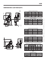
1
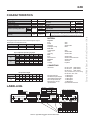
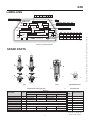
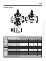
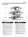
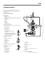
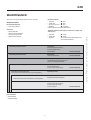
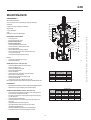
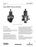
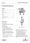
Technical Manual
NTAEZR0206
EZR
July 2004 - Rev 01
PILOT-OPERATED REGULATOR
SUMMARY
INTRODUCTION ................................................................ 1
CHARACTERISTICS .......................................................... 2
LABELLING ......................................................................... 2
SPARE PARTS .................................................................... 3
OPERATION ........................................................................ 5
DIMENSIONS AND WEIGHTS ............................................ 6
INSTALLATION ................................................................... 7
COMMISSIONING ............................................................... 8
MAINTENANCE .................................................................. 9
Type EZR
INTRODUCTION
The EZR is a pilot-operated regulator used in transmission and distribution
networks or pipe lines supplying industries and commercial businesses.
The EZR can be equipped with a slam shut type OS2 (EZR body
change) which permits the gas flow to be cut off rapidly and totally in the
case of under or over outlet regulator pressure.
DESCRIPTION
The EZR consists of:
A version without integral slam shut:
• A body («E body» type), a bonnet
• A regulation subassembly consisting of a slotted cage and a
diaphragm/plug
• A travel indicator, an inlet screen
• A pilot assembly consisting of a filter with bleeding screw (filtration
20 microns), an adjustable restrictor and a pilot set to the required
outlet pressure
A version with integral slam shut:
•
A body («X body» type), a bonnet, a connecting part
• A regulation subassembly consisting of a slotted cage and a
diaphragm/plug
• A travel indicator
• A pilot assembly consisting of a filter with bleeding screw (filtration
20 microns), an adjustable restrictor and a pilot adjusted to the
required outlet pressure
• A removable slam shut orifice
• A integral O-ring tightshut valve/bypass assembly
• A release relay type OS2 according to NTAOS2:
- a mechanism box (BM)
- a safety manometric box (BMS) to be connected outlet side of the
regulator
The EZR is in conformity with the
PED 97/23/EC and is classified in category IV.
Europe, Middle East, and Africa Document Only
DESCRIPTION .................................................................... 1
EZR
CHARACTERISTICS
PS
TS
SLAM SHUT
Pa
ΔP min
0.5 to 48.3 bar
2 to 3 bar
18.6 bar
ΔP max
50.0 bar
55.2 bar
ΔP emerg
72.4 bar
PN 20
PN 50
PN 100
Maximum operating differential
72.4 bar(1)
- 17 / 66 °C(1)
Max emergency differential
Accuracy
AC
Accuracy
AG
Set point range
PILOT
Pt
2.5
5 (Piston)
up to 100 bar
Standard
161EB
Monitor
161EBM
Manometric box
PS BMP
52 bar
Groups 1 and 2 according to PED 97/23/EC, 1st et 2nd family gas
Fluid according to EN 437, or other gases (compressed air, nitrogen). The gas
must be noncorrosive, clean (filtration on inlet side necessary) and dry
Type of pilot
2.5 - 5
(1) Values correspond to the characteristics of the regulator diaphragm
MATERIAL
The regulator body and the slam shut have been designed to support
different pressure and temperature levels
Body
P max (bar)
T min (°C)
T max (°C)
A216WCB
A352LCC
96.7
100
- 20
- 30
71
71
Regulator
Body
Bonnet
Slotted disc
Diaphragm, O-rings
Slam shut
Connecting part
Orifice
Valve plug
Pilot
Body
Manometric box
Restrictor
Filter
Cartridge
B05c
Flow coefficients and valve plug travel
Coefficients Capacity DN 25
100 %
Cg
60 %
30 %
100 %
C1
60 %
30 %
Valve plug travel (mm)
480
290
140
33
29
30
35
DN 50
DN 80 DN 100 DN 150
1800
1020
560
36
28
29
35
3400
1970
970
37
29
26
50
5550
3300
1690
38
27
26
50
11200
7150
3570
36
30
26
50
Steel
Steel
Stainless steel
Nitrile
Steel
Stainless steel
Stainless steel
Stainless steel
Stainless steel or Aluminium
Stainless steel
Aluminium
Polythene
CONNECTIONS
B05a
Inlet / Outlet:
ISO PN 100 B (ANSI 600 RF)
ISO PN 50 B (ANSI 300 RF)
ISO PN 20 B (ANSI 150 RF)
Other possibilities exist (contact factory)
Pilot pressure ranges
BMP size
1
Spring colour
Setting range
(bar)
2
3
4
5
White Yellow Black Green Blue
0.5
1.0
2.8 5.2
9.7
1.0
2.8
5.2 9.7 13.8
6
Red
13.8
24.1
7
8
Blue Red
24.1 31.0
31.0 48.3
B05b
LABELLING
OS2
EZR
BMS Setting
Max only
-
Standard EN 14382 norme
standard
norme
standard
REGULATEUR/REGULATOR
SECURITE/SLAM-SHUT
GROUPE 1 (Gaz Naturel) Cat IV PS
série
N° serial
Date Fab/Test
Mfg/Test date
bar
DD MM YEAR
Min only
Max-Min
Security Class
A
B
BMS 027/017 BMS 162
BMS 236/315 BMS 071
All
types of BMS
DN 25
50 80 100 150
PN 20B1 50B1 100B2 16B 25B 40B
Other configurations available (contact factory)
EN 334
mode défaillance
failure mode
classe sécurité
slam shut class
-
bar Temp TS -17/+66°C
PT
matériau
shell
ISO PN 16 B, 25 B, 40 B
1/4’’ NPT tapped
1/4’’ NPT tapped
1/4’’ NPT tapped
1/4’’ NPT tapped
1/4’’ NPT tapped
Pipe interior Ø 8/10mm min.
Pilot Impulse line (IP):
Pilot Monitor impulse line (IM):
Intermediate impulse line (PI):
Slam shut impulse line (IS):
Mechanism box vent (E):
Impulse diameter:
DN
FISHER
PN
Pumax
bar
Class - Type
FRANCEL
28320 Gallardon-France
Cg
0062
A352LCC+A350LF2
Reduction 100% 60% 30%
Cg
See Flow Table
Depending on BMS configuration
PN
20
Pumax 18.6
PT
32
PS 18.6
50 100 16
50 72.4 16
79 114 26
50 74.4 16
25
25
40
25
40
40
63
40
E04a
Label for Type EZR Regulator with OS2 Slam Shut
2
Europe, Middle East, and Africa Document Only
Operating pressure
Operating temperature
REGULATOR
Outlet pressure
Minimum differential
EZR
LABELLING
PN 20B1 50B1 100B2 16B 25B 40B
Other configurations available (contact factory)
DN 25 50 80 100 150
EZR
REGULATEUR/
REGULATOR
norme
standard
PN
mode défaillance
failure mode
-
Cg
Type DS
série
N° serial
Reduction 100% 60% 30%
Cg
See Flow Table
EN 334
Date Fab/Test
Mfg/Test date
bar
PS
Temp TS
GROUPE 1
bar Pumax
PT
PN
20
Pumax 18.6
PT
32
PS 18.6
A352LCC+A350LF2
FISHER
Cat IV
(Gaz Naturel)
0062
FRANCEL
28320 Gallardon-France
DD MM YEAR
bar
Class -
-17/+66°C
matériau
shell
Date
50 100 16
50 72.4 16
79 114 26
50 74.4 16
25
25
40
25
40
40
63
40
E04b
Label for Type EZR Regulator
SPARE PARTS
B09
B08
Pilot
Filter
Adjustable Restrictor
Pilot, Restrictor, Filter spare parts
Description
Pilot kit 0.34 to 13.8 bar
Pilot kit 13.8 to 24.1 bar
Pilot kit EBH(M)
O-ring
Filter cartridge
O-ring
SAV kit 0.34 to 13.8 bar(1)
SAV kit 13.8 to 24.1 bar(1)
SAV kit 24.1 to 48.3 bar(1)
161EB
R161X000012
R161X000022
197435
197436
161EBH
Pilot spare parts
B11
Reference
Pilot type
Item
15
15
16
17
18
19
B06
161EBM
R161MX00012
R161MX00022
R161HX00012
1C8538X0052
17B6813X012
1F269206992
197438
197439
197437
161EBHM
R161HMX0012
197440
BMP
Size
Spring reference
1
2
3
4
5
6
7
8
17B1260X012
17B1262X012
17B1259X012
17B1261X012
17B1263X012
17B1264X012
17B1263X012
17B1264X012
To pass from 0.5 to 13.8 bar
or from 24.1 to 48.3 bar the
spring must be changed
(1) The SAV kits include item numbers 15 or 16, 17, 18, 19
3
Europe, Middle East, and Africa Document Only
DN
EZR
B12
EZR SPARE PARTS
Regulator
EZR
with
slam shut
EZR without
slam shut
EZR
with/without
slam shut
Description
O-ring
O-ring
Guide
O-ring
Bypass
SAV kit PN 20
SAV kit PN 50/100
SAV kit PN 20
SAV kit PN 50/100
O-ring
O-ring
O-ring
O-ring
PN 20 diaphragm
PN 50/100 diaphragm
O-ring
O-ring
O-ring
O-ring
Safety manometric box
Item
1
2
3
4
5
1 to 14
1 to 14
6 to 14
6 to 14
6
7
8
9
10
10
11
12
13
14
25 (1’’)
400009
19B2838X012
401950
400527
180977
197421
197421
197428
197428
18B3438X012
1H2926X0032
13A1584X052
19B2838X012
39B2397X012
39B2397X012
13A1584X052
1E216306992
14A5713X012
50 (2’’)
400024
18B2124X012
401951
400263
180977
197422
197423
197429
197430
18B3438X012
1H2926X0032
13A1584X052
18B2124X012
29B2715X022
28B2123X052
13A1584X052
1E26306992
10B4428X012
Reference
DN mm (inches)
80 (3’’)
400091
18B8514X012
401952
400258
180977
197424
197424
197431
197431
10A8931X012
1D191706992
10A3803X062
18B8514X012
39B2726X012
39B2726X012
10A3803X062
1J4888X0052
10B4366X012
100 (4’’)
400045
18B2140X012
401953
400260
180977
197425
197426
197432
197433
10A8931X012
1D191706992
10A3803X062
18B2140X012
38B5965X012
39B3996X012
10A3803X062
1J4888X0052
10B4373X012
150 (6’’)
400262
19B0359X012
401954
400261
180977
197427
197427
197434
197434
10A3800X012
1D191706992
T12050X0012
19B0359X012
49B0357X012
49B0357X012
T12050X0012
11A8741X052
1H862306992
1D269206992
See NTAOS2 manual
B13
4
Europe, Middle East, and Africa Document Only
SPARE PARTS
EZR
OPERATION
REGULATOR
The pressure loss through the pilot restrictor decreases.
The EZR is a pilot-driven, diaphragm/plug regulator.
The force of the closing spring and that of the Pm becomes superior
to that provoked by the Pe, the regulator CLOSES.
Tight shutoff is achieved by the diaphragm/plug pushing against the slotted
cage, the force of the closing spring and the inlet pressure.
SLAM SHUT
Opening
The pressure of the zone to be protected (generally the pipeline on the
outlet side of the regulator and after the slam shut) is sensed by the
safety manometric box (BMS).
As the flow increases, the outlet pressure Pa decreases on the outlet
side of the regulator and on the pilot diaphragm.
Due to the force of the spring, the pilot opens.
If the pressure exceeds the set tripping pressure, the release relay frees
the valve plug.
The pilot flow increases, the pressure loss through the pilot restrictor
increases.
•
The modulated pressure Pm decreases.
Due to the force of the closing spring and the fluid (trying to close), the
valve plug closes on the orifice.
The force of the closing spring and that of the Pm becomes inferior to
that provoked by the Pe, the regulator OPENS.
The gas flow is obstructed until the fault has been corrected and the
mechanism box manually rearmed.
Closing
To reopen the valve plug an equal pressure balance on inlet and outlet
sides of the regulator is required.
As the flow decreases, the Pa increases outlet side of the regulator.
The mechanism box is rearmed after opening the internal bypass.
The force of the pilot diaphragm is overcome by the force of the
spring, the pilot closes.
Rearming and balancing are achieved at the same time.
B18
5
Europe, Middle East, and Africa Document Only
•
EZR
DIMENSIONS AND WEIGHTS
Dimensions with slam shut (mm)
A
M
D
J
E
Body DN
B
C
E
H
25
50
80
100
150
233
243
361
393
423
315
330
366
410
396
348
357
410
454
468
250
265
301
345
332
B15b
B
H
C
F
NC = FE
BL A TE = CLRME
I
OSE
WH
D
Body DN
PN 20
PN 50
PN 100
25
50
80
100
150
20
39
63
104
192
21
41
69
113
211
22
43
71
123
244
B16b
NC = FE
BL A TE = C RME
LOS
I
WH
ED
G
25 Disassembly
B14a
Dimensions without slam shut (mm)
Body DN
B
C
E
25
50
80
100
150
220
226
343
372
420
62
83
105
137
178
335
340
392
433
465
B15a
Regulator weight (kg)
M
D
J
Body DN
PN 20
PN 50
PN 100
25
50
80
100
150
12
26
50
67
97
14
27
51
73
108
16
31
57
88
161
B16a
E
Body dimensions with/without integral slam shut (mm)
A
Body DN
PN
D
J
M
20
50
100
25 (1")
184
197
210
165
68
54
50 (2")
254
267
286
165
68
54
80 (3")
298
317
337
181
95
54
100 (4")
352
368
394
187
95
54
150 (6")
451
473
508
249
95
54
B
C
A
B14b
B17a
BMS
(Safety Manometric Box)
Type
F
G
Diaphragm
Piston
Bellows
162
71
74
181
204
223
B17b
6
Europe, Middle East, and Africa Document Only
Regulator weight (kg)
EZR
B19
All interventions on the equipment should only be performed by
qualified and trained personnel.
!
•
•
•
•
•
•
•
•
•
WARNING
!
•
The regulator is installed on horizontal pipeline. Version with
slam shut, the release relay is situated towards the bottom (see
schematic).
Installation according to EN12186 recommended.
Install according to direction of fluid flow (arrow).
When assembling with adjacent elements care must be taken
not to create pressure force on the body and the assembling
elements (bolts, O-rings, flanges) should be compatible with
the geometry and working conditions of the equipment.
If the case arises a support must be used to avoid pressure
force on the body (a support can be installed under the
flanges).
Version with integral slam shut , connect the safety
manometric box (IS) to the impulse at 4D on a straight run of
the outlet pipe.
It is recommended to separate the slam shut impulse line (IS)
from that of the pilot (IP). Do not connect the impulses on the
lower generator line.
It is recommended to install an isolation valve and an
atmospheric valve, which can be useful for slam shut tripping
and verifications.
No modification should be made to the structure of the
equipment (drilling, grinding, soldering...).
•
•
•
•
•
•
•
7
WARNING
It is recommended to install a servicing valve on the outlet
pipeline to facilitate adjustments and bleeding off to the
atmosphere.
Verify that the inlet side is protected by an appropriate
device(s) to avoid exceeding the limits of utilization (PS, TS).
Verify that the limits of utilization correspond to the appropriate operating conditions.
Version with integral slam shut, verify that the safety
manometric box (BMS) and spring correspond to the appropriate operating conditions on the outlet side of the regulator.
The equipment should not receive any type of shock, especially the release relay.
The user should verify or carry out a protection adapted to the
environment.
Fire, seismic and lightening are not taken into consideration
in standard regulators. If required, a special product selection
and/or specific calculations may be supplied according to
specific requirements.
Version without integral slam shut, verify that a pressure
limiting device on the outlet side of the regulator guarantees a
pressure limit inferior or equal to the pilot PS.
Europe, Middle East, and Africa Document Only
INSTALLATION
EZR
COMMISSIONING
Operations concerning the integral slam shut version are in italic.
All interventions on equipment should only be performed by
qualified personnel
PRELIMINARY VERIFICATIONS
• Inlet and outlet valves
Æ Closed
Verify the absence of pressure between inlet and outlet valves
• Slam shut valve plug
Æ Closed
• Pilot A
Æ Unloaded
• Restriction B
Æ START position
Slam shut set point verification
Using the atmospheric valve, inject a pressure equal to the pressure
required for the regulator
• 1st release relay stage
Æ Set (Stage 1)
• Slam shut valve plug
Æ Open (Stages 2 & 3)
Æ Progressively increase the pressure to
reach tripping
Æ Adjust setting if necessary (NTAOS2)
Note the set point value on the equipment
or mark it on a commissioning document
Positions before commissioning
• Impulse line isolating valve
Æ Open
Triggered
position
B22
• Impulse line atmospheric valve
Æ Closed
• Slam shut valve plug
Æ Closed
• Servicing valve
Æ Closed
• Servicing valve
Æ Open slightly
Stage 1
The equipment is ready for commissioning
• Pilot
Æ Screw to set outlet pressure
COMMISSIONING (Act slowly)
• Outlet valve
Æ Open slowly
• Inlet valve
Æ Open very slowly
• 1st release relay stage
Æ Set (Stage 1)
• Slam shut valve plug
Æ Bypass (Stage 2)
• Restriction
Æ Set to "RUN" by successive fractions 2, 4 or 6
• Servicing valve
Æ Closed
Stages 2 and 3
B20
The equipment is commissioned
Æ Open (Stage 3)
It is recommended to seal the release relay
8
Europe, Middle East, and Africa Document Only
Start-up positions
EZR
MAINTENANCE
Departure positions
Operations concerning the integral slam shut version are in italic.
•
•
•
•
Æ Open
Inlet valve
Æ Open
Outlet valve
Slam shut valve plug Æ Open
Æ In operation
Regulator
Inlet and outlet sides of regulator under pressure
SERVICING CHECK
Recommended frequency:
• Twice yearly minimum
Verification:
Tightshut verification (and tripping verification for integral slam
shut versions)
Set point verification
Regulator valve plug tightness
Tripping and set point value
Slam shut valve tightness
•
•
•
If the outlet pressure increases
If the outlet pressure decreases
If the outlet pressure is constant
Inlet valve
Outlet valve
Regulator
Æ Closed
Æ Closed
Observe the evolution of the outlet pressure
(control regulator tightness)
Internal leak
Control the regulator valve plug
Control the regulator orifice
Control the pilot
or contact after-sales
External leak
Locate and seal the leak
or contact after-sales
The regulator is tightshut
Increase the set point until tripping occurs
(without exceeding the outlet limits)
If the slam shut valve plug will not close
Operating fault
Control the release relay
Control the slam shut valve plug
If the slam shut valve plug closes
Observe the evolution of the outlet pressure (control tightness)
or contact after-sales
Operating correctly
If the outlet pressure is constant
Purge the outlet side of the regulator
Observe the evolution of the outlet pressure (control tightness)
If the outlet pressure increases
Internal leak
Control the slam shut valve plug
Control the slam shut orifice
Control the bypass
If the outlet pressure is constant
Slam shut valve plug is tightshut
Filter verification
•
•
Purge the filter C
Verify the cartridge
9
or contact after-sales
Europe, Middle East, and Africa Document Only
•
•
•
•
EZR
MAINTENANCE
DISASSEMBLY
Recommended frequency:
Every 2 to 6 years (or less depending on operating conditions)
Verification:
Condition of O-rings, diaphragms, lubrication
Replacement:
O-rings, diaphragm
PRELIMINARY OPERATIONS
•
•
•
•
•
•
•
•
•
Valve plug closed
Inlet and outlet valves closed
Bleed off outlet pressure
Bleed off inlet pressure
Unscrew the pilot impulse connection
Unscrew the screws 1 fixing the bonnet 2
Remove the bonnet 2
Remove the diaphragm/plug assembly 3
Remove the slotted cage 4, the O-ring 5, the strainer 6
(or the space washer 6)
• Clean parts and replace them if necessary
PILOT
• Unscrew the manometric box screws
• Remove the diaphragm
B24
SLAM SHUT (Version with slam shut)
• Unscrew the BMS impulse line connector (IS)
• Remove the BM cover 7
• Unscrew the BM fixing screw 8
• Remove the holding pin 10
• Remove the BM 9
• Unscrew the screws 11 from the connecting part 12
• Remove the connecting part 12
• Remove the spring 13 and the valve plug 14
• Unscrew the bypass 15
• Unscrew the screws CHC 16 (DN 100 and 150)
Removing the orifice 17 (not recommended) requires a special extraction tool
Body DN
25
50
80
100
150
(1'')
(2'')
(3'')
(4'')
(6'')
Screws
Items 1 and 11
9/16 - 12 x 1 3/4
1/2 - 13 x 1 1/2
5/8 - 11 x 1 3/4
3/4 - 10 x 2 1/4
1 - 8 x 2 3/4
Spanner
(inches)
13/16
3/4
15/16
1 1/8
1 1/2
B25a
REASSEMBLY
• Perform the above operations in reverse order (respect tightening torques)
• Replace the O-rings and diaphragm at each disassembly
SLAM SHUT REASSEMBLY (Version with slam shut)
Body DN
• The valve plug should be held in an upper position using a packing
gland and a box to facilitate reassembly
• Precaution must be taken concerning the passage of the valve plug
over the segments
• Lubricate screws before tightening
• Lightly lubricate the O-rings (silicone grease) except for the valve
plug O-ring
• Lightly lubricate the stem (silicone grease)
• Lubricate the release relay mechanism (yoke and bolt)
(molybdenum graphite grease)
• Lubricate the BMS spring (molybdenum graphite grease)
• A special tool is required for reassembling a new orifice
25 (1'')
50 (2'')
80 (3'')
100 (4'')
150 (6'')
10
Screw
Item 1 & 11
110
110
175
260
510
Torque N.m.
Fixation Connector
Item 18
Item 19
8
130
9
130
28
280
28
280
70
410
Bypass
Item 15
14
14
20
24
24
B25b
Europe, Middle East, and Africa Document Only
Tools:
Dimensions according to tables below
Natural Gas Technologies
Emerson Process Management
Regulator Technologies, Inc.
Francel SA
Z.A. La Croix Saint Mathieu
28320 Gallardon, France
Tel : +33 (0)2 37 33 47 00
Fax : +33 (0)2 37 31 46 56
O.M.T. Officina Meccanica Tartarini s.r.l.
Via P. Fabbri, 1
I - 40013 Castel Maggiore (Bologna), Italy
Tel. : +39 - 0514190611
Fax: +39 - 0514190715
E-mail: [email protected]
For further information visit www.emersonprocess.com/regulators
The Emerson logo is a trademark and service mark of Emerson Electric Co. All other marks are the property of their prospective owners. Fisher is a mark owned by Fisher Controls, Inc., a business
of Emerson Process Management.
The contents of this publication are presented for informational purposes only, and while every effort has been made to ensure their accuracy, they are not to be construed as warranties or guarantees,
express or implied, regarding the products or services described herein or their use or applicability. We reserve the right to modify or improve the designs or specifications of such products at any time
without notice.
Emerson Process Management does not assume responsibility for the selection, use or maintenance of any product. Responsibility for proper selection, use and maintenance of any Emerson Process
Management product remains solely with the purchaser.
©Emerson Process Management Regulator Technologies, Inc., 2009; All Rights Reserved
11
Europe, Middle East, and Africa Document Only
EZR