1
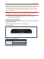
Avocent® Universal Management Gateway Appliance
Installer/User Guide
For important safety information, visit:
www.emersonnetworkpower.com/ComplianceRegulatoryInfo
Emerson, Emerson Network Power and the Emerson Network Power logo are trademarks or service marks of Emerson Electric
Co. Avocent, the Avocent logo, Cyclades, DSView and Trellis are trademarks or service marks of Avocent Corporation. Liebert is a
trademark or registered trademark of Liebert Corp. All other marks are the property of their respective owners. This document may
contain confidential and/or proprietary information of Avocent Corporation, and its receipt or possession does not convey any right
to reproduce, disclose its contents, or to manufacture or sell anything that it may describe. Reproduction, disclosure, or use without
specific authorization from Avocent Corporation is strictly prohibited. ©2014 Avocent Corporation. All rights reserved.
NOTE: This document supports versions up to and including release 2.8.
i
TABLE OF CONTENTS
Product Overview
Features and Benefits
Secure access
Autosense
Web user interface (UI)
VGA and USB connections
CLI setup port
IPv4 and IPv6 support
Security
Data logging, notifications, alarms and data buffering
Power management
Auto discovery
Control of virtual media and smart card-capable appliances
Flexible users and groups
DSView™ management software plug-in
Installation
Supplied with the Appliance
Rack and Wall Mounting
Rack mounting
Rack mount safety considerations
Wall mounting
Cabling installation, maintenance and safety tips
Connecting the Hardware
Appliance connectors
Connecting targets
Turning On the Appliance
Verifying the Connections
Front and rear panel power status LEDs
Rear panel Ethernet connection LEDs
Rear panel autosensing/dedicated IP port LEDs
Configuring the Appliance
Configuration Example
Using Telnet or SSH to access a serial target
Initial Appliance Setup
Connecting to Your Network
Assigning an IP Address
Connecting Locally or Through the Console Port
Setting Up Your Network
Firewall
Port requirements
Web User Interface
1
1
1
1
3
3
3
4
4
4
4
4
5
5
5
7
7
7
7
8
8
9
11
11
12
14
14
14
15
15
15
16
18
21
21
21
21
22
23
24
27
ii.....Avocent® Universal Management Gateway Appliance Installer/User Guide
Web UI Overview
Using the Sidebar
Admin role
Operator role
User role
Tabs
Targets
Sensors
Events
Administration
Administration
Appliance Settings
SSH
Help File
Email Settings
Defaults
Network Settings
Network modes
Bridge Group Configuration
Hosts
Routes
OSPF and BGP
Network Share
Users
User role group
Users group
Password Policy
Preemption Levels
Adding a user
Authentication
User Target Access
User Target Rights
Groups
Targets
Licenses
Port configuration
SP management
Firmware upgrade and repository
Serial management
PDU management
Asset Location
RFID tag
KVM management
27
28
29
29
29
29
30
30
30
30
31
31
32
32
32
32
33
33
34
36
36
37
39
39
39
40
40
40
41
42
44
44
44
50
50
50
60
61
62
66
69
69
69
Table of Contents..... iii
Target groups
Startup
Firmware
Backing up firmware
USB Devices
Sensors
Com Digital Input
Digital inputs
Environment
RS-485 environment sensor
PDU Temperature Sensors Delta
Monitoring
Email
Syslog
Digital Output
Sessions
Support
Security
Certificate
Firewall and NAT
Interfaces
Defined networks
Hosts
Services
Policy
Targets
Service Processors
Properties
System
SEL
Sessions
Power
Sensors
Logs
Alert Destinations
UMIQ Modules
KVM session optimization
Serial Console
PDU
Properties
Outlets
Overview
79
80
80
81
82
82
83
84
84
85
85
86
86
86
87
88
88
89
89
90
90
92
94
96
98
105
106
106
106
107
107
109
110
110
110
110
110
112
112
112
113
113
iv.....Avocent® Universal Management Gateway Appliance Installer/User Guide
Current, Voltage, Power Consumption, Energy Consumption
Settings
Power Outlet
Sensors and Events
Sensors
Events
Fan
Temperature
Power
CPU and disk usage
Appendices
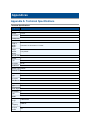
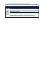
Appendix A: Technical Specifications
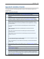
Appendix B: Installation Checklist
Appendix C: Forgotten Password
Appendix D: Booting from the Network
Appendix E: Creating an SP File
Appendix F: Troubleshooting SPs
Appendix G: Appliance Troubleshooting
LAN performance
WAN performance
Bridge groups
Hardware
Appendix H: Troubleshooting From the Appliance Shell
Network related
Appendix I: IP Masquerading for 1-to-1 NAT
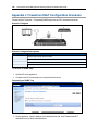
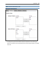
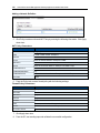
Appendix J: Firewall and NAT Configuration Scenarios
Appendix K: SNMP Configuration
Appendix L: Video Resolution
113
113
115
117
117
117
117
117
117
118
119
119
121
123
124
125
126
127
127
127
128
128
129
129
131
132
135
136
Product Overview
The Avocent® Universal Management Gateway appliance serves as a single point for secure local
and remote access and administration of target devices. The Avocent® Universal Management
Gateway appliance supports secure remote data center management and out-of-band
management of IT assets from any location worldwide. It provides keyboard, video and mouse
(KVM) capabilities and can also remotely perform server management tasks, including power
control and console access, on managed target devices. Multiple administrators can be logged into
the appliance at the same time and can use the web user interface (UI), the command line interface
(CLI) or DSView™ 4 management software to access and configure the appliance.
NOTE: All instances of DSView™ software in this document refer to DSView™ software version 4 or
higher.
The Avocent® Universal Management Gateway appliance combines KVM over IP, Service
Processor Management (SPM) and access and serial console management access. It gives you
flexible target device management control and secure remote access from anywhere at anytime.
Features and Benefits
Secure access
You can securely access the appliance through the following local (analog console port) and
remote (digital IP) options:
•
LAN/WAN IP network connection.
•
Serial target device connection. An authorized user can make a Telnet, SSH v1, SSH v2 or
raw connection to a target device. For Telnet or SSH to be used for serial target device
connections, the Telnet or SSH service must be configured in the Security Profile that is in
effect.
•
Console connection. An administrator can log in either from a local terminal or from a
computer with a terminal emulation program that is connected to the console port and can use
the CLI.
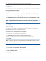
Autosense
The Avocent® Universal Management Gateway 2000 appliance has eight autosensing ports that
can be used for either service processor (SP) or serial connectivity and management. It has an
additional 32 RJ-45 ports which are intended solely for SP connectivity and management. The
2.....Avocent® Universal Management Gateway Appliance Installer/User Guide
Avocent® Universal Management Gateway 4000 and 6000 appliances have 40 autosensing ports
that can be used for service processor (SP) or serial connectivity and management.
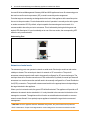
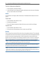
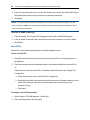
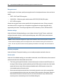
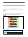
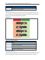
Ports that support autosensing are designated on the back of the appliance with a small turquoise
line next to the port number. Ports indicate which mode of operation is currently active with a green
or amber connection LED. By default, all ports capable of autosensing are in automode. It is
recommended to leave the port set to autosense. This is indicated by having both the green and
amber LEDs illuminated. If a port is statically set to one of the two modes, the corresponding LED
will be the only one illuminated.
Autosensing Port
Network and serial mode
The autosensing ports can operate in network or serial mode. Each major mode has sub modes
called port classes. The network port class is for network or SP connections. The port will
autosense network targets but will need to be manually configured for SP connected targets. The
serial port class is for console connections or PDU connections. By default, the serial port class will
autosense to a console connection and will need to be manually configured for a Power Distribution
Unit (PDU) connection. The ports will autosense and switch to the appropriate mode depending on
the target attached to the appliance.
When a port is in network mode, the green LED will be illuminated. The appliance will provide an IP
address to the network device attached to it. It is only intended to be connected to the device to be
managed or accessed. The appliance will not function as a traditional network switch or common
network access firewall. It is a special purpose appliance intended for target device access and
management.
CAUTION: Since the appliance issues IP addresses using DHCP, they could conflict with a production
DHCP infrastructure. Proper VLAN segmentation must be assigned on the network to avoid this conflict.
Product Overview..... 3
IP addresses can also be assigned statically to SPs, and the appliance can scan IP ranges to
discover them.
When a port is in serial mode, the amber LED will be illuminated. The appliance will assign the
console port class by default and auto-detect whether to apply the Avocent or Cisco® soft pinout.
The speed, flow control, parity and data-size are all predefined for connectivity to standard RS-232
server consoles but can be modified on a per-port basis. In addition to console mode, a supported
Avocent PDU can be connected to and managed from the appliance.
Web user interface (UI)
Users and administrators can perform most tasks through the web UI (accessed with HTTPS). The
web UI runs in Microsoft Internet Explorer® and Mozilla Firefox® browsers on any supported
computer that has network access to the appliance.
An administrator can use the web UI to create user accounts, authorize groups and configure
security and ports. Authorized users can access connected devices through the web UI to
troubleshoot, maintain, cycle power, or to reboot connected devices and change their password.
For more information on the web UI, see Chapter 3.
VGA and USB connections
Standard VGA and USB connections can be used to attach an LCD tray. These ports are located
on the front of the appliance. The VGA console port can be used for launching sessions to targets
or for performing NetBoot firmware recoveries. The USB ports are used for connecting USB
keyboard, mouse, smart card reader, CD, DVD or mass storage devices.
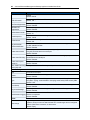
VGA Console Hotkeys
Key Combination Operation
Alt + Tab
Toggle to next view in a cyclic list
Alt + F1
View web UI
Alt + F2
View User Shell
Alt + Esc
Close current view and session
NOTE: Press ALT-F1 during the appliance boot progress screen to display verbose output.
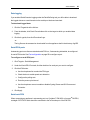
CLI setup port
The serial setup port provides access to the CLI and Shell. The appliance does not support root
access to the Bash Shell. The CLI is intended for managing and configuring the appliance.
4.....Avocent® Universal Management Gateway Appliance Installer/User Guide
IPv4 and IPv6 support
The appliance supports dual stack IPv4 and IPv6 protocols. The administrator can use the web UI
or CLI to configure support for IPv4 and/or IPv6 addresses. The following list describes the IPv4
and IPv6 support provided in the appliance:
•
DHCP
•
DSView software integration
•
Ethernet interfaces, GB1 (eth0) and GB2 (GB2 (eth1))
•
Firewall (IP tables)
•
HTTPS
•
Linux kernel
•
Remote authentication: AD and LDAP servers
•
SSH and Telnet access
•
Syslog server
NOTE: Remote authentication NFS, NIS and IPSec are not supported with IPv6.
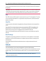
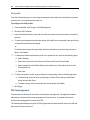
Security
The Security settings allow administrators to determine which network services are enabled on the
appliance.
Data logging, notifications, alarms and data buffering
An administrator can set up data logging, notifications and alarms to alert administrators of
problems with email and syslog messages. An administrator can also store buffered data locally.
Messages about the appliance and connected servers or devices can also be sent to syslog
servers.
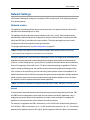
Power management
The Avocent® Universal Management Gateway appliance enables users who are authorized for
rack power distribution units (PDU) and service processor (SP) power management to turn power
on, turn power off and reset servers via their embedded SP devices plugged into a connected rack
PDU.
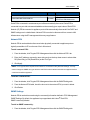
Auto discovery
An administrator can enable auto discovery to find the hostname of a target connected to a port.
Auto discovery’s default probe and answer strings have a broad range. An administrator can
Product Overview..... 5
configure site-specific probe and answer strings. Auto discovery can also be configured through
the DSView™ software.
Supported SPs
The appliance supports rack and blade server SPs from the following vendors: Dell®, HP, IBM®,
Cisco®, Fujitsu®, Oracle® Sun and additional IPMI implementations. For a complete list of SPs
supported by your appliance, visit www.avocent.com/updates to see the release notes that match
your appliance firmware version.
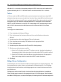
Control of virtual media and smart card-capable appliances
The Avocent® Universal Management Gateway appliance allows you to view, move or copy data
located on virtual media to and from any target device. Manage remote systems more efficiently by
allowing operating system installation, operating system recovery, hard drive recovery or
duplication, BIOS updating and target device backup.
Smart cards such as the Common Access Card (CAC) can be used to store identification and
authentication to enable access to computers, networks and secure rooms or buildings.
Virtual media and smart card readers can be connected directly by using USB ports located on the
appliance. In addition, virtual media and smart card readers may be connected to any remote
workstation that is running the remote web UI or DSView™ management software and is
connected to the appliance using an Ethernet connection.
Flexible users and groups
An account can be defined for each user on the appliance or on an authentication server. An
administrator has an account by default and can add and configure other user accounts. Access to
ports can be optionally restricted based on authorizations an administrator can assign to custom
user groups.
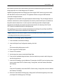
DSView™ management software plug-in
The DSView™ management software may be used with the appliance to allow IT administrators to
remotely access, monitor and control target devices on multiple platforms through a single, webbased user interface. DSView™ software proxy and SSH Pass-through features enable
convenient and secure remote access for LAN and WAN clients. For more information, see the
DSView™ 4 Management Software Plug-In for the Avocent® Universal Management Gateway
Appliance Technical Bulletin.
6.....Avocent® Universal Management Gateway Appliance Installer/User Guide
Installation
Before installing your Avocent® Universal Management Gateway appliance, refer to the following
list to ensure you have all items that shipped with it, as well as other items necessary for proper
installation.
Supplied with the Appliance
•
Appliance Quick Installation Guide (QIG)
•
Avocent® Universal Management Gateway Appliance Mounting Bracket Quick
Installation Guide (QIG)
•
Power Cords
•
RJ-45 to DB-9F cross adaptor
•
Mounting brackets and screws
•
Safety and Regulatory Statements Guide
Rack and Wall Mounting
You can mount the appliance in a rack or cabinet; or, using the optional wall-mounting kit, you can
mount it on a wall.
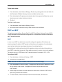
Rack mounting
To rack mount the appliance:
1. Remove the four black screws from each side of the Avocent® Universal Management
Gateway appliance. Position each bracket so it is not covering the side vents of the appliance.
Secure the mounting brackets to the appliance using the eight chrome screws supplied with
the appliance.
2. Loosely attach the two slide-rail brackets to the front of the rack using the appropriate screws
for your rack.
3. From the rear of the rack, slide the appliance into the same U position where the slide rails are
mounted. Ensure that both slide rails are securely inserted into the appliance bracket. Tighten
the rack screws for both the appliance bracket and the slide rails.
8.....Avocent® Universal Management Gateway Appliance Installer/User Guide
Bracket Connections for Rack Mount Configuration
Rack mount safety considerations
•
Elevated Ambient Temperature: If installed in a closed rack assembly, the operating
temperature of the rack environment may be greater than room ambient. Use care not to
exceed the rated maximum ambient temperature of the appliance.
•
Reduced Air Flow: Installation of the equipment in a rack should be such that the amount of
airflow required for safe operation of the equipment is not compromised.
•
Mechanical Loading: Mounting of the equipment in the rack should be such that a hazardous
condition is not achieved due to uneven mechanical loading.
•
Circuit Overloading: Consideration should be given to the connection of the equipment to the
supply circuit and the effect that overloading of circuits might have on overcurrent protection
and supply wiring. Consider equipment nameplate ratings for maximum current.
•
Reliable Earthing: Reliable earthing of rack mounted equipment should be maintained. Pay
particular attention to supply connections other than direct connections to the branch circuit
(for example, use of power strips).
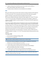
Wall mounting
NOTE: The wall-mounting kit is optional and is not included with the appliance; it must be purchased
separately. For details on how to purchase the wall-mounting kit, contact your Avocent representative.
To wall mount the appliance:
1. Using the slots on the bracket or the supplied template as a guide, mark the holes in the
plywood wall where the brackets are to be fastened. A minimum of two holes for each bracket
Installation..... 9
should be marked. Use a 3/16-inch drill bit to drill guide holes at the marked positions. Using
1/4 inch by 1 inch hex lag screws (not included with the wall-mounting kit), secure each
bracket to the plywood wall, using at least two screws for each bracket.
2. Remove the two middle truss-head screws from each side of the appliance. It is important to
remove only the middle two screws allowing the cover of the appliance to stay secured. Align
the holes in the appliance with the holes in the mounted brackets and, using the thumb screws
provided with the wall-mounting kit, secure it to the brackets with the slots facing up or down,
as illustrated.
Bracket Connections for Wall Mount Configuration
Wall and 0U mounting safety considerations
Wall mounting is permitted with an optional wall-mounting kit (sold separately). If wall mounting or
0U mounting in an equipment rack, the appliance must be mounted so that its front face is facing
sideways and not toward the floor or ceiling.
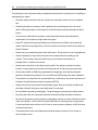
Cabling installation, maintenance and safety tips
WARNING: To avoid potentially fatal shock hazard and possible damage to equipment, please observe the
following precautions.
10.....Avocent® Universal Management Gateway Appliance Installer/User Guide
The following is a list of important safety considerations that should be reviewed prior to installing or
maintaining your cables:
•
Dress the cables neatly with cable ties, using low to moderate pressure. Do not overtighten
ties.
•
If bending the cable is necessary, make it gradual with no bend sharper than a one inch
radius. Allowing the cable to be sharply bent or kinked can permanently damage the cable’s
interior.
•
Cross-connect cables where necessary, using rated punch blocks, patch panels and
components. Do not splice or bridge cable at any point.
•
Keep UTP cable as far away as possible from potential sources of EMI, such as electrical
cables, transformers and light fixtures. Do not tie cables to electrical conduits or lay cables on
electrical fixtures.
•
Always test every installed segment with a cable tester. Toning alone is not an acceptable test.
•
Always install jacks so as to prevent dust and other contaminants from settling on the
contacts. The contacts of the jack should face up on the flush mounted plates, or
left/right/down on surface mount boxes.
•
Always leave extra slack on the cables, neatly coiled in the ceiling or nearest concealed
location. Leave at least five feet at the work outlet side and 10 feet at the patch panel side.
•
Choose either 568A or 568B wiring standard before beginning. Wire all jacks and patch
panels for the same wiring scheme. Don’t mix 568A and 568B wiring in the same installation.
•
This product is not intended to be connected directly or indirectly by any means whatsoever to
interfaces of public telecommunications networks (PSTN).
•
Always obey all local and national fire and building codes. Be sure to firestop all cables that
penetrate a firewall. Use plenum rated cable where it is required.
•
Do not disable the power grounding plug. The grounding plug is an important safety feature.
•
Plug the power cord into a grounded (earthed) outlet that is easily accessible at all times.
•
Disconnect the power from the product by unplugging the power cord from either the electrical
outlet or the product. The AC inlet is the main disconnect for removing power to this product.
For products that have more than one AC inlet, to remove power completely, all AC line cords
must be disconnected.
•
This product has no user-serviceable parts inside the product enclosure. Do not open or
remove product cover.
Installation..... 11
CAUTION: This appliance contains an internal battery that is used for the real-time clock. This battery is
not a field replaceable item, and replacement should not be attempted by a user. If real-time clock errors
occur and the battery is suspected, visit http://www.avocent.com/support or contact the Avocent Technical
Support location nearest you.
WARNING: For Service Personnel Only - There is a risk of explosion if the battery is replaced with an
incorrect type. Dispose of used batteries according to the manufacturer’s instructions.
•
This product is for use with other products that are Listed or Certified by a Nationally
Recognized Testing Laboratory (NRTL).
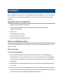
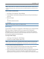
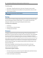
Connecting the Hardware
Appliance connectors
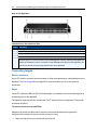
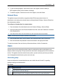
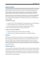
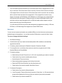
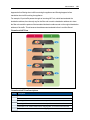
The following figure shows the connectors on the front of the appliance.
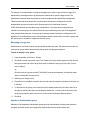
Front of the Appliance
Connectors on the Appliance Front
Number
Description
1
LED
2
Console Port
3
USB Connections
4
Analog Video Port
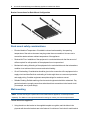
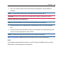
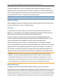
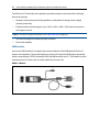
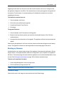
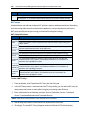
The following figure shows the rear connectors on the appliance.
12.....Avocent® Universal Management Gateway Appliance Installer/User Guide
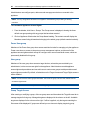
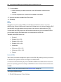
Rear of the Appliance
Connectors on the Appliance Rear
Number Description
1
Power supplies.
2
Power Indication LED.
3
GB2 (eth1) 10/100M/1G Ethernet port. Can be connected to a second network or used for failover.
4
Sensors
Autosensing ports. On the Avocent® Universal Management Gateway 4000 and 6000 appliances,
5
all ports are autosensing. On the Avocent® Universal Management Gateway 2000 appliance, the
eight ports on the left are autosensing and the other 32 are dedicated.
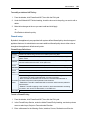
Connecting targets
Service processor
Use a UTP cable to connect a service processor to either an autosensing or a dedicated port on the
appliance. See Port configuration on page 50 for more information on how to set up service
processors.
Serial
Use a UTP cable and a DB-9 or DB-25 console adaptor, as needed, to connect a serial target to an
autosensing port on the appliance.
The appliance supports both the Avocent and Cisco® serial port pinout configuration. The port will
autosense the pinout.
To connect serial devices and PDUs:
Make sure the crossover cable used to connect a device has the same pinout type that is
configured in the software for the port (either Avocent or Cisco).
1. Make sure the devices to be connected are turned off.
Installation..... 13
2. Use a UTP crossover cable to connect the devices to the appliance, using an adaptor, if
necessary.
NOTE: To comply with EMC requirements, use shielded cables for all port connections.
WARNING: Do not turn on the power on the connected devices until after the appliance is turned on.
To daisy chain PDUs to the appliance:
NOTE: This procedure assumes you have one PDU connected to a port on the appliance.
1. Connect one end of a UTP cable with RJ-45 connectors to the OUT port of the connected
PDU.
2. Connect the other end of the cable to the IN port of the chained PDU. Repeat both steps until
you have connected the desired number of PDUs.
NOTE: For performance reasons,do not connect more than 128 outlets per serial port.
See Port configuration on page 50 for more information on how to set up serial targets.
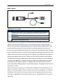
KVM If your appliance supports KVM connections, use a UTP cable and a UMIQ module to connect a
KVM target to an autosensing port on the appliance.
14.....Avocent® Universal Management Gateway Appliance Installer/User Guide
UMIQ Module Configuration
The UMIQ-v1 module has a single RJ-45 port to connect to the appliance. The UMIQ-v2 module
has two RJ-45 ports. You can connect either one to the appliance and the other to a dedicated
service processor port on the server. The cable length can be up to 100 meters long.
See KVM management on page 69 for more information about KVM targets.
Turning On the Appliance
The appliance is supplied with dual power supplies.
To turn on the appliance:
1. Plug the power cables into the appliance and into a power source.
2. Turn on the connected devices.
Verifying the Connections
Front and rear panel power status LEDs
The front panel of appliance has a dual-color general status LED that may illuminate:
Installation..... 15
•
The LED illuminates green when the appliance is turned on and operating normally.
•
The LED blinks green when the appliance is booting.
•
The LED illuminates amber if a fault condition occurs, such as power supply failure, elevated
ambient temperature or fan failure. The LED will continue to illuminate amber as long as the
failure persists.
•
The LED blinks amber when the appliance is shutting down. Once the LED is off, it is safe to
unplug the power cords.
Rear panel Ethernet connection LEDs
On the appliance, the rear panel features two LEDs where the green LED indicates Ethernet
connection status:
•
The solid green LED denotes an Ethernet link has been established.
•
The blinking green LED denotes Ethernet activity.
•
The solid amber LED denotes a target session is active.
•
No LEDs illuminated denotes no activity.
Rear panel autosensing/dedicated IP port LEDs
The rear panel of the appliance features two LEDs, green or amber:
•
If both LEDs are illuminated, autosensing is enabled.
•
The green LED illuminates when there is a KVM or SP connection.
•
The amber LED illuminates when there is a serial connection.
Configuring the Appliance
The appliance may be accessed through the CLI or the console or Ethernet ports. All terminal
commands are accessed through a terminal or PC running terminal emulation software.
NOTE: To configure using DSView™ software, see the DSView™ 4 Management Software Installer/User
Guide. To configure using the appliance's web UI, see Administration on page 31. To configure using Telnet
or SSH, see the appliance Command Reference Guide.
To connect a terminal to the appliance:
1. Using a null modem cable, connect a terminal or a PC that is running terminal emulation
software to the console port on the front panel of the appliance. An RJ-45 to DB9 (female)
cross adaptor is provided.
16.....Avocent® Universal Management Gateway Appliance Installer/User Guide
The terminal settings are 9600 bits per second (bps), 8 bits, 1 stop bit, no parity and no flow
control.
2. Turn on the appliance. When the appliance completes initialization, the terminal will display
the login banner plus the login prompt.
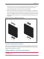
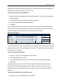
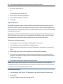
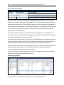
Configuration Example
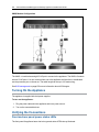
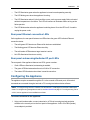
The following graphic and table illustrate a typical appliance configuration.
Installation..... 17
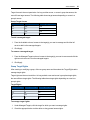
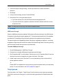
Typical Avocent® Universal Management Gateway Appliance Configuration
Typical Avocent® Universal Management Gateway Appliance Configuration
Descriptions
Number Description
Number Description
1
11
Power supplies
DSView server
18.....Avocent® Universal Management Gateway Appliance Installer/User Guide
Number Description
Number Description
2
Ethernet connection
12
Remote authentication
3
User
13
PC client
4
External sensors connection
14
USB media
5
Autosensing ports for serial or service
processor targets
15
RJ-45 serial setup port
6
UMIQ module for KVM connection
16
DB9 com port
7
Target server (VGA/USB)
17
PC for local configuration
8
Firewall
18
USB connection (keyboard, mouse
or media)
9
Ethernet connection
19
VGA console port
10
Local Area Network (LAN)
20
LCD tray for local configuration
and access
Using Telnet or SSH to access a serial target
An authorized user can use a Telnet or SSH client to make a connection directly to the console of a
serial target if all of the following are true.
The Telnet or SSH:
•
protocol is enabled for network service in the security profile
•
protocol is configured for the port
•
client is available, and it is enabled on the computer from which the connection is made
To use Telnet to connect to a target through a serial port:
For this procedure, you need the username configured to access the serial port, the target name
(for example, 14-35-60-p-1), device name (for example, ttyS1), TCP port alias (for example, 7001)
and the hostname of the appliance or its IP address.
To use a Telnet client, enter the information in the dialog boxes of the client.
-orTo use Telnet in a shell, enter the following command:
# telnet [hostname | IP_address]
login: [username]:[targetname | device_name]
-or-
# telnet [hostname | IP_address] TCP_Port_Alias
login: [username]
To close a Telnet session:
Enter the Telnet hotkey defined for the client. The default is Ctrl + q to quit.
Installation..... 19
To use SSH to connect to a target through a serial port:
For this procedure, you need the username configured to access the serial port, the target name
(for example, 14-35-60-p-1), TCP port alias (for example, 7001), device name (for example, ttyS1),
and the hostname of the appliance or IP address.
To use an SSH client, enter the information in the dialog boxes of the client.
-orTo use SSH in a shell, enter the following command:
ssh -l [username]:[target_name] [hostname | IP_address]
-or-
ssh -l [username]:[device name] [hostname | IP_address]
-or-
ssh -l [username:TCP_Port_Alias] [hostname | IP_address]
To close an SSH session:
At the beginning of a line, enter the hotkey defined for the SSH client followed by a period. The
default is ~ .
20.....Avocent® Universal Management Gateway Appliance Installer/User Guide
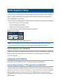
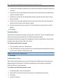
Initial Appliance Setup
The Avocent® Universal Management Gateway appliance provides extensive access to attached
devices. Consider the following security parameters and default values and how they align with
your organizational security policies.
The Avocent® Universal Management Gateway appliance ships with the following default settings: •
DHCP, SSH v2 and HTTPS are enabled.
•
All autosensing ports are enabled.
•
Ethernet and CLI Setup ports are enabled.
•
The following are default user accounts within the appliance.
Default User Accounts
Username Role
Password
admin
admin
admin
operator
power-user operator
user
user
•
user
Shell access is permitted for admin roles only.
NOTE: Avocent strongly recommends you change the default passwords after initial setup and create
individual user accounts. For information on changing passwords, see Adding a user on page 41.
Connecting to Your Network
Connect a UTP cable from the primary network port to your network. For redundancy, connect both
network ports and configure the fail-over network mode. For more information, see Defined
networks on page 92.
Assigning an IP Address
An IP address can be obtained via DHCP, or a static IP address can be assigned.
Connecting Locally or Through the Console Port
You can configure and manage the appliance via the network from a supported web browser, via
the VGA console from an LCD tray or KVM switch, or via the CLI Setup port using a serial cable and
terminal emulation software. Use the provided RJ-45 to DB9F adapter to connect a terminal or
workstation to the CLI Setup port. Terminal settings are: 9600, 8, N and 1 with no flow control and
ANSI emulation.
22.....Avocent® Universal Management Gateway Appliance Installer/User Guide
NOTE: For instructions on assigning an IP address using the CLI, see the Universal Management Gateway
Appliance Command Reference Guide.
The GB1 (eth0) port on the appliance is configured as a DHCP client. If your network is set up for
DHCP, you must first find the IP address assigned to the appliance by looking at the DHCP leases
on the network DHCP server. Then use a supported web browser to navigate to https://<appliance
IP> to connect to the appliance.
NOTE: Adobe® Flash Player and Oracle® Java Runtime are required for full product support to client PCs
accessing the appliance. See the release notes for a list of supported web browsers.
If your network is not set up for DHCP, the GB2 (eth1) port has a default IP address of
192.168.1.10. You can assign your PC connected to eth1 an IP address of 192.168.1.10 and then
browse to the appliance using the default IP address.
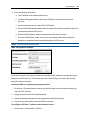
To assign the IP address using the VGA console: 1. Log in to the appliance using admin as both the default username and password.
2. Under the Administration tab, click Network Settings. For more information on Network
Modes, see Defined networks on page 92.
NOTE: Changes to the network mode should be performed before targets are configured. Changing the
network mode after adding and configuring targets may interrupt their communication, and they may need
to be added again and reconfigured in order to work again.
3. Click the entry for the desired interface in the table and change the method to Static.
4. Assign the desired IP values and click Apply.
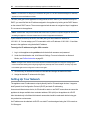
Setting Up Your Network
The appliance uses IP addresses to uniquely identify itself to IP-based target devices. It supports
both Dynamic Host Configuration Protocol (DHCP) and static IP addressing.
As a network infrastructure device, its IPs should be static or use DHCP reservations to ensure the
appliance is always available via a consistent address. GB1 (eth0) on the appliance is a DHCP
client intended only to facilitate initial network access but should be made static before being put
into production environments.
An IP address can be obtained via DHCP or a static IP can be assigned using the VGA console or
CLI Setup port.
Initial Appliance Setup..... 23
NOTE: If using DHCP, you must first find the IP address assigned to the appliance by looking at the DHCP
leases on the network DHCP server. Enter https://<appliance IP> in your browser to connect to the
appliance.
To assign the IP address:
1. Log in to the appliance via its console port using admin as both the username and password.
2. Click the Administration button.
3. Click the Network Settings folder.
4. Click the GB1 (eth0) entry in the table and change the method to Static.
5. Assign the desired IP values and click Apply.
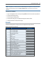
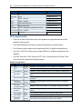
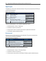
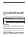
Firewall
Consult the following table to configure access to the appliance through a firewall.
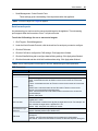
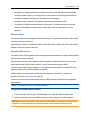
Default Firewall Service Definitions
Port
Type
Service Definition
0
ICMP - Ping
srv-PING
20
FTP - Firmware Update
srv-FTP-Data
21
FTP - Firmware Update
srv-FTP-Commands
22
Encrypted Serial Session
srv-SSH-Serial-Session
23
Telnet Session
srv-Telnet-Session
69
TFTP
srv-TFTP-Services
161
SNMP Set/Get
srv-SNMP
162
SNMP Traps
srv-SNMP-Traps
443
Encrypted Web UI Access
srvWEB-UI
502
Trellis™ Platform (Modbus Communication)
srv-Modbus
514
External Syslog
srv-External-syslog
623
Serial over LAN and IPMI
NA
843
Web UI Data - Flash
srv-Adboe-Flex
1078
DSView™ Proxy Port (Default)
srv-DS-View-proxy
2068
Encrypted KVM Session
srv-KVM-session
3211
DSView™ Discovery (UDP)
srv-Discovery-protocol
3212
UMIQ srv-DRIP-protocol
3502
DSView™ Software Appliance Communications srv-DS-View-plug-in
3871
DSView™ Communication (ADSAP2)
srv-Security-protocol
4112
DSView™ Data Logging - Syslog
srv-Data-logging-DSView
4440
Trellis™ Management Protocol
srv-UMG-Service-2
24.....Avocent® Universal Management Gateway Appliance Installer/User Guide
Port
Type
Service Definition
6443
Trellis™ Platform OHS Service
srv-Trellis-Platform-OHS
7001-7040
Serial
srv-UMG-Service-9
8011
Trellis™ Platform
srv-UMG-Service-3
8012
Trellis™ Platform
srv-UMG-Service-4
8080
Java Viewer Download
srv-UMG-Service-6
8123
Web UI Data - XML
srv-UMG-Service-7
9002-9003
Trellis™ Intelligence Engine Event Service
srv-Trellis-Event (-2)
47777-48117 Trellis™ Platform
NA
50000-59999 SP Access
NA
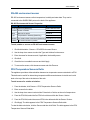
Port requirements
•
Ports 443, 843 and 8123 must be open to the appliance to support administration of the
appliance using its web UI.
•
Ports 2068 and 8080 must be open to support KVM sessions to a UMIQ module.
•
Port 22 must be open to support serial sessions and SSH-CLI appliance administration.
•
Ports 3211, 3502, 3871 must be open to support DSView™ software management of the
appliance.
•
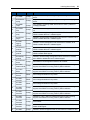
Ports 502, 6443, 8011, 8012, 9002 and 47777-48117 must be open for full Trellis™ RealTime Infrastructure Optimization Platform support.
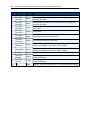
Default Firewall Rules
Order Service
Action
Use-case recommendation
1
any
Accept
Needed for internal appliance communication. Do not disable.
2
any
Accept
Needed for internal appliance communication. Do not disable.
3
srv-WEB-UI
Accept
Needed to access the appliance web UI, set to DROP to disable web UI.
4
srv-PING
Accept
Needed to test/troubleshoot network connectivity, set to DROP if not
used.
5
srv-FTP-Data
Accept
Needed to upgrade appliance firmware via the web UI, set to DROP
otherwise.
6
srv-FTPCommands
Accept
Needed to upgrade appliance firmware via the web UI, set to DROP
otherwise.
7
srv-SSHAccept
Serial-Session
Needed to launch serial session or to manage the appliance via SSH.
8
srv-TelnetSession
Accept
Option to manage the appliance via Telnet, set to DROP if not using
Telnet.
9
srv-DHCPD
DROP
Don't change this default unless using DHCP Relay feature.
10
srv-DHCPD
DROP
Don't change this default unless using DHCP Relay feature.
11
srv-TFTPServices
Accept
Not needed for current appliance features, set to DROP.
Initial Appliance Setup..... 25
Order Service
Action
Use-case recommendation
12
srv-SNMP
Accept
Only needed if centrally monitoring the appliance using a central SNMP
server.
13
srv-Externalsyslog
Accept
Only needed if centrally logging the appliance using a central Syslog
server.
14
srv-SNMPTraps
Accept
Only needed if monitoring SNMP devices for the Trellis™ platform or
managing NetPDUs.
15
srv-AdobeFlex
Accept
Needed to access the appliance web UI, set to DROP to disable the web
UI.
16
srv-DSViewproxy
Accept
Needed to access appliance targets with DSView™ software, set to
DROP to disable DSView™ software support.
17
srv-DSViewplug-in
Accept
Needed to access/manage the appliance with DSView™ software, set to
DROP to disable DSView™ software support.
18
srv-DataloggingDSView
Accept
Needed to monitor the appliance with the DSView™ software, set to
DROP to disable DSView™ software support.
19
srv-DiscoveryAccept
protocol
Needed to discover the appliance with the DSView™ software, set to
DROP to disable DSView™ software support.
20
srv-DRIPprotocol
Accept
Needed on private ports to discover and manage UMIQ modules, set to
DROP to disable KVM support.
21
srv-Securityprotocol
Accept
Needed to access/manage the appliance with the DSView™ software,
set to DROP to disable DSView™ software support.
22
srv-PXE-bootAccept
server
Not needed for current appliance features, set to DROP.
23
srv-TrellisAccept
Platform-OHS
Needed for Trellis™ platform software management and monitoring
support, set to DROP if not using Trellis™ platform software.
24
srv-TrellisEvent
Accept
Needed for Trellis™ platform software management and monitoring
support, set to DROP if not using Trellis™ platform software.
25
srv-TrellisEvent-2
DROP
Don't change this default for any reason.
26
srv-UMGService-1
DROP
Don't change this default for any reason.
27
srv-UMGService-1
DROP
Don't change this default for any reason.
28
srv-UMGService-2
Accept
Needed for Trellis™ platform software management and monitoring
support, set to DROP if not using Trellis™ platform software.
29
srv-UMGService-4
Accept
Needed for Trellis™ platform software management and monitoring
support, set to DROP if not using Trellis™ platform software.
30
srv-UMGService-5
Accept
Needed for Trellis™ platform software management and monitoring
support, set to DROP if not using Trellis™ platform software.
31
srv-UMGService-6
Accept
Set to DROP.
32
srv-UMGService-7
Accept
Needed to support KVM sessions to UMIQ modules, set to DROP to
disable KVM support.
33
srv-UMG-
Accept
Needed to access the appliance web UI, set to DROP to disable the web
26.....Avocent® Universal Management Gateway Appliance Installer/User Guide
Order Service
Action
Service-8
Use-case recommendation
UI.
34
srv-UMGService-8
DROP
Needed only by the local host for the VGA console, Don't change this
default for any reason.
35
srv-UMGService-9
DROP
Needed only by the local host for the VGA console, Don't change this
default for any reason.
36
srv-UMGService-10
Accept
Needed for direct serial port access using Telnet, set to DROP in not
using Telnet.
37
srv-UMGService-11
Accept
Set to DROP.
38
srv-UMGService-12
DROP
Don't change this default for any reason.
39
srv-UMGService-13
DROP
Don't change this default for any reason.
40
srv-VelocityBACNet
Accept
Only needed if monitoring BACnet over IP devices for the Trellis™
platform, set to DROP if not using the Trellis™ platform.
41
srv-Modbus
Accept
Only needed if monitoring Modbus over IP devices for the Trellis™
platform, set to DROP if not using the Trellis™ platform.
42
srv-DNS
Accept
Needed to support DNS resolution, set to DROP to block DNS support.
48
srv-KVMsession
Accept
Needed to support KVM sessions to UMIQ modules, set to DROP to
disable KVM support.
49
srv-KVMsession
Accept
Needed to support KVM sessions to UMIQ modules set to DROP to
disable KVM support.
512
Any
DROP
Needed to protect general packet relay, not recommended to be changed
Web User Interface
Once you have connected the Avocent® Universal Management Gateway appliance to a network,
you can access the appliance with its web user interface (UI). The web UI provides direct access to
the appliance and its target devices via a graphical user interface.
NOTE: For instructions on accessing the appliance via the command line interface or DSView™ software
see the Avocent® Universal Management Gateway Appliance Command Reference Guide or the
DSView™ 4 Management Software Installer/User Guide.
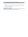
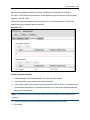
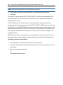
Web UI Overview
To log into the web UI:
1. Open a web browser to the address http://<appliance.IP>.
2. At the login screen, enter your username and password.
3. After logging in, you will see the Targets tab.
NOTE: When using the VGA console, you can choose alternate locales or keyboard types.
NOTE: Adobe® Flash Player and Oracle® Java Runtime are required for full product support to client PCs
accessing the appliance. See the release notes for a list of supported web browsers.
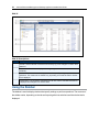
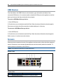
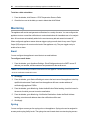
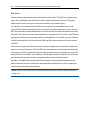
28.....Avocent® Universal Management Gateway Appliance Installer/User Guide
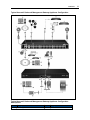
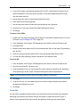
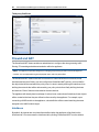
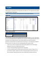
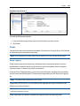
Web UI
Web UI Descriptions
Number Description
1
Title bar - Use the title bar to access the online help, log out or change the current user's
password.
2
Tab bar - Use the tab bar to display and manage targets, sensors, events, administration
and alerts.
3
Sidebar - The sidebar is used to display windows that specify settings or perform
operations. The contents of the sidebar vary, depending on the tab bar and the window
that is displayed.
4
Content area - The information specified by the tab bar, title bar and sidebar selections
is displayed and changed in the content area.
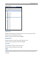
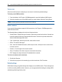
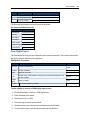
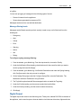
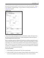
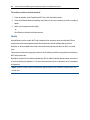
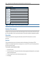
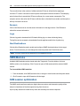
Using the Sidebar
The sidebar is used to display windows that specify settings or perform operations. The contents of
the sidebar varies, depending on the tab and top navigation bar selections and the window that is
displayed.
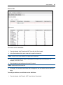
Web User Interface..... 29
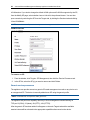
Example Sidebar
Admin role
By default, Admins have access to all the tabs of the web UI. Admins can access the Targets,
Sensors, Events and Administration tabs of the UI.
By default, the login and password for Admins is admin.
Operator role
Operators can access the Targets, Sensors and Events tabs of the UI.
By default, the login and password for Operators is operator.
User role
Users can access the Targets and Sensor tabs of the UI.
By default, the login and password for Users is user.
Tabs
The tabs are the major navigation areas of the web UI. Only certain actions can be performed in
certain tabs.
30.....Avocent® Universal Management Gateway Appliance Installer/User Guide
Targets
The information shown in the Targets tab is primarily read-only and is intended to facilitate user
access to target sessions or target control. For more information, see Targets on page 105.
Sensors
The Sensors tab is only visible on a Avocent® Universal Management Gateway 4000 or 6000
appliance. From this tab, you can view read-only information regarding temperature, humidity, dry
contact, smoke, motion, leak and other supported environmental data. For more information, see
Sensors and Events on page 117.
Events
The Events tab contains the event and alert logs for the appliance. The data shown on this tab is
read-only except for the ability to clear event and alert entries. For more information, see Sensors
and Events on page 117.
Administration
The Administration tab contains all the necessary configuration and control settings to administer
and operate the appliance and its targets. The only configuration parameters not accessible from
this tab are relevant to the Trellis™ Real-Time Infrastructure Optimization Platform's data collection
and monitoring capability. That behavior is fully controlled within the Trellis™ platform. See the
following section for more information.
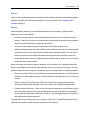
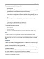
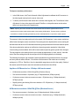
Administration
When logging in as an Administrator, you will have access to the Administration tab. From this tab,
you can configure and manage the appliance and its associated targets.
NOTE: The actions in this section can be performed by first clicking the Administration tab.
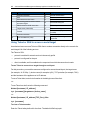
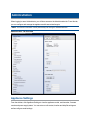
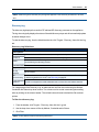
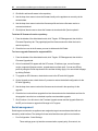
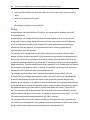
Administration Tab Overview
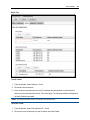
Appliance Settings
From the sidebar, click Appliance Settings to view the appliance model, serial number, firmware
version and power supply status. You can enter or edit contact, location and help file settings as
well as configure email settings.
32.....Avocent® Universal Management Gateway Appliance Installer/User Guide
You can use the buttons at the top of the screen to reboot, shut down or launch an SSH session to
the appliance.
WARNING: Always execute the shutdown command through the web UI, CLI or DSView™ software under
the Overview/Tools node before turning the appliance off, then on again. This will ensure the reset doesn't
occur while the file system in Flash is being accessed, and it helps to avoid Flash memory corruptions.
SSH
Click SSH to launch an SSH-based CLI console session from your PC to the appliance. From here
you can access the Administration CLI, target sessions and power actions, as well as access the
appliance Linux Shell.
Help File
You can access the online help for the appliance by clicking the Help button in the top right of the
screen.
If your client PCs do not have internet access, you may download a PDF of the appliance user
guide and host it on an internal web server. To download the user guide, go to the following
address: http://pcs.mktg.avocent.com/@@content/manual/5901071501b.pdf.
Once you've downloaded the user guide and hosted it on a server, enter its path in the Help File
URL field.
Email Settings
The appliance can generate email alerts for events that occur on the appliance or its associated
target devices. Once an SMTP/email server is configured, alerts can be sent to as many as four
email addresses.
See the Monitoring and Notification destination sections to configure alerts and their email
recipients.
Defaults
From the Defaults tab, you can restore the appliance to its factory default settings.
You can also configure the date and time, NTP server settings as well as setting the time zone and
daylight savings. If you do not have access to an NTP server, you can manually set the date and
time.
NOTE: You have to set the time on the appliance before enrolling it in the Trellis™ Real-Time
Infrastructure Optimization platform.
Administration..... 33
Network Settings
Click Network Settings to configure the hostname, DNS, domain name, IPv4 default gateway and
IPv6 default gateway.
Network modes
The appliance provides agentless remote access and control. No special software or drivers are
required on the attached servers or client.
The appliance has three physical network interfaces (eth0, eth1, priv0). Each interface has an
individual MAC address and can be configured for normal or failover modes. Only the public GB1
(eth0) and GB2 (eth1) are visible to the user interface. The 40 private target ports are virtually
configured to connect through the internal priv0 interface.
To configure individual ports, see Port configuration on page 50.
NOTE: Changes to the appliance network mode will invalidate default firewall rules and can interrupt
communication with the appliance. See below for more information.
Placing the appliance into Failover mode or adding eth0 or eth1 to a Bridge group will disable the IP
addresses currently assigned to some/all appliance interfaces. New interfaces will be activated
(Failover = bond0, Bridge group = <group name>). By default, the new interface will not inherit any
former IPs assigned to either eth0 or eth1. For best results when placing an appliance in Failover
mode or creating a Bridge group, the operator should perform the configuration changes via the
VGA console or the serial Setup port to avoid losing communication access to the appliance. All
firewall rules that reference interfaces replaced during the network configuration change should be
edited to ensure proper network communication when operating the appliance in the new mode.
(i.e. eth0/eth1 must be replaced with bond0 where applicable).
NOTE: The default IP addresses for the appliance are: GB1 (eth0) = DHCP, GB2 (eth1) = 192.168.1.10
Normal
In Normal mode, the public interfaces and the public target ports are separated by a firewall. GB1
and GB2 function independent of each other and can assume individual IP addresses. Only a
single gateway can be defined for the appliance, but static routes are helpful for enabling the
appliance to communicate with various subnets from either interface.
For example: An appliance with GB1 connected to a 192.168.200.x/24 network with a gateway of
192.168.200.1. GB2 is connected to a 10.1.0.x/24 network with a gateway of 10.1.0.1. If the default
gateway for the appliance is set to GB1 (eth0), then the appliance will not be able to communicate
34.....Avocent® Universal Management Gateway Appliance Installer/User Guide
with other 10.x.x.x networks via the gateway assigned to GB2. A static route can be added to the
appliance indicating that 10.1.0.1 should be used to communicate with all 10.x.x.x subnets.
Failover
In Failover mode, the GB1 and GB2 interfaces are both activated and each has a unique MAC
address but they share a common bond0 virtual interface. Only a single MAC exists for the shared
bond0 interface and only a single IP can be assigned to bond0. When data needs to be sent from
the appliance, only GB1 will send it using the bond0 MAC/IP. When traffic is sent to the bond0
MAC/IP, only GB1 will receive it, since only GB1 is responding to ARP requests using the bond0
MAC. If GB1 is disconnected, then GB2 assumes control of the bond0 MAC/IP for all data
exchange.
To configure a network device:
1. From the sidebar, click Network Settings.
2. Enter the hostname (the hostname will be used for e-mail notifications as the sender
address).
3. Use the drop-down list to select Normal or Failover for the mode.
4. Enter the primary and secondary DNS addresses in the appropriate fields.
5. Enter the domain name.
6. Use the drop-down lists to select the IPv4 and IPv6 default gateways.
7. Click the name of the interface to modify it.
a. Under the IPv4 heading, enter the MTU, address, netmask, broadcast and gateway in
the appropriate fields. Use the drop-down list to select either DHCP or static for method.
b. Under the IPv6 heading, enter the address, netmask and gateway in the appropriate
fields. Use the drop-down list to select either DHCP or static for method.
8. Click Apply.
Bridge Group Configuration
An administrator can choose network interfaces to bridge together into a logical bridge group. This
feature simplifies the creation, deletion and maintenance of bridged interfaces. You can bridge
both physical and virtual interfaces, and bridging supports user-created interfaces as well as the
pre-defined ones.
A bridge group can be created for each virtual and physical interface defined on the appliance.
When a bridge group is created, it will be assigned a Layer 3 IPv4/IPv6 address. When interfaces
are added to a bridge group, a prompt will be displayed, indicating that all IP addresses assigned to
Administration..... 35
the interfaces will be lost and communication with devices accessible through the ports within the
bridge group will occur via the bridge group's IP address.
Appliance interfaces placed into a bridge group will not support DHCP services to prevent conflict
with other DHCP services on the network. The appliance will also not support UMIQ modules
connected to bridged interfaces.
The appliance is not intended to be a general purpose ethernet bridge. The port bridging feature is
intended to make devices, which are physically connected to private interface ports, accessible via
the public network infrastructure. In order to prevent a switching loop when multiple bridged
interfaces are accidentally connected to the same network switch, the Spanning Tree Protocol
(STP) feature is enabled by default for all bridge groups.
If the appliance is connected to a network switch with an active Bridge Protocol Data Unit (BPDU)
Guard, the STP feature must be disabled for the bridge group.
NOTE: Disabling STP will cause the appliance to store and forward ethernet frames between the ports of
the bridge group without any switching loop prevention.
To create or edit a bridge group configuration: 1. From the sidebar, click Network Settings.
2. Under the Bridge Group Configuration heading, click Add.
-orClick on an existing bridge group to edit it.
3. Enter a name for the bridge group.
4. Ensure STP is enabled.
5. Use the drop-down menu to enable the Bridge State.
6. From the list of available bridge interfaces, select the interfaces you want to add to the group
and click the right arrow.
7. Under the IPv4 heading, enter the Maximum Transmission Unit (MTU) and use the drop-down
menu to select either DHCP or Static routing. If using Static, enter the Address, Broadcast
and Gateway.
-orUnder the IPv6 heading, enter either DHCP or Static routing. If using Static, enter the Address
and Gateway. Click Apply.
8. Back on the main Network Settings page, change the IPv4/IPv6 default gateway to the name
you assigned to the bridge group. Click Apply.
36.....Avocent® Universal Management Gateway Appliance Installer/User Guide
To delete a bridge group configuration: 1. From the sidebar, click Network Settings.
2. Under the Bridge Group Configuration heading, check the box next to the name of the bridge
group you want to delete, then click Delete.
Hosts
An administrator can configure a table of host names, IP addresses and host aliases for the local
network.
To add a host:
1. From the sidebar, select Network - Hosts.
2. Click Add to add a new host.
3. Enter the IP address, hostname and alias of the host you want to add, then click Apply.
To delete a host:
1. From the sidebar, select Network - Hosts.
2. Click on the name of the hostname you want to delete, then click Delete.
Routes
Proper routing will ensure that traffic flows from clients to the appliance and back. The routing table
in the appliance shows the networks that are connected as well as networks the appliance has been
told about or have been learned dynamically. If traffic is destined for a remote network but the
appliance cannot find a specific route matching the destination network, it will revert to sending the
traffic to its default gateway. This is why some traffic does not get sent or received as expected.
NOTE: The appliance is specially designed for managing and providing access to device management
consoles. It is not supported as a general purpose router, switch or packet filter.
Static routes to specific network destinations can improve the accuracy of the decisions made by
the appliance about which interface to use when sending traffic.
NOTE: It is important to ensure there is never a duplicated network address assigned to more than one
interface within the appliance. It is also important to change the default private network addresses within the
appliance if they conflict with networks already present within your infrastructure.
Administration..... 37
To add static routes:
1. From the sidebar, select Network Settings - Routes. Any existing static routes are listed with
their Destination IP/Mask, Gateway, Interface and Metric values shown.
2. Enter the destination IP, gateway and netmask values in the appropriate fields, then use the
drop-down menu to select the device interface.
3. Click Add.
To delete a static route:
1. From the sidebar, select Network Settings- Routes.
2. Click on the name of the static route you want to delete, then click Delete.
OSPF and BGP
The appliance supports Open Shortest Path First (OSPF) and Border Gateway Protocol (BGP)
routing standards and their associated configurations. An administrator can add, edit and delete
OSPF and BGP networks.
OSPF
In order to use OSPF, an administrator must first configure the appliance ID, interfaces and
networks settings. By default, OSPF speaks to all interfaces on the appliance. An administrator
cannot add an interface but may change the status of an existing interface.
An administrator is able to add a network for the appliance to give and receive information from
other OSPF nodes within the network. When adding a network, it must be unique to the appliance.
The network value is in CIDR format of an IP address/netmask, for example: 10.12.1.0/24.
To configure OSPF: 1. From the sidebar, click Network Settings - OSPF.
2. Check the box to enable OSPF.
NOTE: When OSPF is enabled or disabled, an alert will be sent to the alert manager.
3. Enter the appliance ID, then click Apply. The appliance ID should be an IP address, but it can
be any arbitrary 32-bit number. The appliance ID must be unique within the entire
OSPF domain.
4. Use the drop-down menus to set the Interfaces to either Active or Passive. OSPF will not
speak to any interface set to Passive.
5. To add a network, enter the address for the network and its area, then click Add.
38.....Avocent® Universal Management Gateway Appliance Installer/User Guide
6. To edit an existing network, check the box next to the network under the Modify an
OSPF Network heading. When finished, click Apply.
7. To delete a network, check the box next to the network, then click Delete.
BGP
BGP is one of the key protocols used to achieve internet connection redundancy. BGP appliances
use TCP protocol on port 179 to communicate with each other. BGP sends only incremental
updates containing the routing entries that have changed since the last update.
BGP peers are established by manual configuration between appliances to create a TCP session
on port 179. Every 30 seconds, a BGP speaker will send keep-alive messages to maintain the
connection. Each BGP appliance maintains a separate TCP session with other BGP appliances to
which it is connected.
An Autonomous System (AS) is a group of IT networks run by one or more network operators with
a single, clearly defined routing policy. When exchanging routing information, each AS is identified
by a unique number. The 16-bit number range is from 0 to 65535. From 64512 to 65535 is reserved
for private use. Exterior routing protocols such as BGP are used to exchange routing information
between Autonomous Systems. An AS will normally use some interior gateway protocol to
exchange routing information on its internal networks. The network value is in CIDR format of an
IP address/netmask, for example: 10.12.1.0/24. The configured network will be announced to all its
neighbors.
To configure BGP: 1. From the sidebar, click Network Settings - BGP.
2. Check the box to enable BGP.
NOTE: When BGP is enabled or disabled, an alert will be sent to the alert manager.
3. Enter the AS number and appliance ID, then click Apply. The appliance ID should be an
IP address, but it can be any arbitrary 32-bit number.
4. To add a network, enter the address for the network then click Add.
5. To edit an existing network, check the box next to the network under the Modify a
BGP network heading. When finished, click Apply.
6. To delete a network, check the box next to the network, then click Delete.
7. To add a neighbor (peer), enter its IP address and remote-AS number then click Add.
NOTE: The default AS number is 64512, which is a private AS number. You will need to modify it when
using BGP to make sure it's unique in the network.
Administration..... 39
8. To edit an existing neighbor, check the box next to the neighbor under the Modify a
BGP neighbor heading. When finished, click Apply.
9. To delete a neighbor, check the box next to the neighbor, then click Delete.
Network Share
The appliance supports the ability to upgrade multiple SPs through network share. An
administrator can configure the network share by clicking Network Settings - Network Share from
the Administration sidebar.
To configure a Samba client for network share: 1. From the sidebar of the Administration tab, click Network Settings - Network Share.
2. Under the Settings tab, in the External Samba Server field, enter the IP address or hostname
of the Samba server.
3. In the Share Path field, enter the subdirectory that represents the network share.
NOTE: The field may be left empty to represent the root directory.
4. In the Domain Name field, enter the name of the Windows domain name of the server.
5. Enter the username and password for the network share in the appropriate fields.
To view the contents of the root directory of the network share, click the Contents tab.
Users
Access to ports can be optionally restricted, based on authorizations that an administrator can
assign to custom user groups. Groups can also be authorized to manage power while connected to
devices. The appliance has three default users (admin, operator and user) and three pre-defined
user roles(appliance administrator, power-user and user).
User role group
A user role defines the view and what the user can do within the web UI and CLI, regarding
appliance settings and administration.
User Roles
User Role Description
User
Target access only.
PowerUser
View appliance information, reboot appliance, disconnect user sessions, target access, target
power operations and view data logs.
Appliance- All user and administrator functions including upgrading the appliance, configuring appliance
Admin
settings and target access. The Appliance-Admin role is the only one with shell access.
40.....Avocent® Universal Management Gateway Appliance Installer/User Guide
Users group
A user account must be defined for each user on the appliance or on an authentication server. Only
an admin can add and configure other user accounts. Each local user account is assigned to one or
more of the user groups.
CAUTION: Change the default passwords before you put the appliance into operation.
Password Policy
The default username and password for the appliance is admin and admin. An administrator may
configure global password rules to all user accounts. The maximum length of a password is 64
characters. When the password policy is increased from a lower level to a higher one, all local user
accounts will be flagged to change the password at next login.
In all cases, passwords will be checked to ensure they are not comprised of palindromes or
repeated strings.
Password Policy Settings
Setting Description
None
Passwords can be as short as one character and may contain any character. Passwords
can be immediately re-used. Password expiration is set to never by default.
Weak
Passwords must contain at least four characters, at least one of which must be a
number. When a user changes a password, it must be different from the old password.
Passwords are set to expire after one year, by default.
Passwords must contain at least eight characters, including one number and one capital
Medium letter. When a user changes a password, it must be different from the old password.
Passwords are set to expire after 90 days, by default.
Strong
Passwords must contain at least 16 characters, including one special character, one
number and one capital letter. When a user changes a password, it must be different
from the old password. Passwords are set to expire after 30 days, by default.
Preemption Levels
The preemption level of users determines whether they may interrupt or disconnect another user’s
KVM session with a target device. Administrators and user administrators may specify the
preemption level for user accounts or user-defined user groups.
By default, the preemption level active for the user is the highest assigned value of all of the user
groups to which the user belongs. Preemption levels range from 1-6, with 6 being the highest level.
For example, a user or a user group with a preemption level of 6 may preempt other level 6 users or
user groups, as well as those with a level 1, 2, 3, 4 or 5 setting.
Administration..... 41
User and User Group Preemption
Preemption
Level
Description
6
The default level for the admin account. Only available to admins.
5
The default level for the factory operator account. Only available to operators and
administrators.
4
The default level for a new local user of a KVM switch or serial console appliance.
3
The default level for the Avocent® Universal Management Gateway Appliance .
2
The default level for the user administrator user group.
1
Default for new users. The default for the Factory user account.
The preemption levels may be used in the following ways:
•
User preemption level - This is the preemption level assigned to a user by an administrator. If
this value is larger than the highest preemption level of the user group to which the user
belongs, the value will be used as the effective user preemption level.
•
Group preemption level - This is the preemption level assigned to user groups to which the
user belongs. If the user is assigned to multiple user groups with different preemption levels,
this will be the preemption level of the user group with the highest level. For example, if a user
belongs to the appliance administrators (level 6) and users (level 1) user groups, this value will
be defined as 6. If this value is larger than the highest preemption level of the user, the value
will be used as the effective user preemption level.
An appliance administrator or power user may also specify a local user interface preemption level
that is applied to users accessing target devices through the local interface.
Adding a user
To add or modify a user: 1. From the sidebar, click Users.
2. Click Add to create a new user. The Create User screen appears. Enter the new username
and password and use the drop-down menu to define the user role (User, Power-User or
Admin).
-orClick the name of a user to modify that user. The Modify User screen appears. Enter a new
password for the User and use the drop-down menu to change the user role.
3. Define the preemption level.
4. Check the box if you want the password to be changed at the next login.
42.....Avocent® Universal Management Gateway Appliance Installer/User Guide
5. Check the box to enable the session time-out and enter the number of minutes for the time-out
in the field.
6. Check the box to have the password expire and then enter either the number of days before it
expires or the date it expires.
7. Check the box to warn the user the password will expire and then enter the number of days
before in the field.
8. Check the box to have the password expire if the account is inactive and enter the number of
days the account must be inactive before it expires.
9. Use the arrows to put the user in a group. For more information on groups, see Groups on
page 44.
10. Click Apply.
Authentication
Authentication can be performed locally, through LDAP or a DSView™ server. The appliance also
supports remote group authorizations for the LDAP authentication method.
Any authentication method configured for the appliance is used for authentication of any user who
attempts to log in through Telnet, SSH or the web UI.
To configure authentication settings:
1. From the sidebar, click Users - Authentication.
2. From the Settings tab, use the drop-down menu to select the password strength, then use the
arrow buttons to select the authentication order.
NOTE: Password strength is a global setting.
3. Click Apply.
Authentication servers
When using an authentication server, you must configure its IP address and in most cases other
parameters before it can be used. The following authentication servers require configuration:
LDAP and DSView™ software servers.
To configure an LDAP authentication server:
1. Click Administration–Users–Authentication.
2. Select LDAP from the Not Used column and move it to the Methods Used column.
3. Click Apply.
4. Select the LDAP tab.
Administration..... 43
5. Enter the following information:
a. The IP address of the authentication server.
b. The Base Distinguished Name, which is the LDAP path to the location of the user
accounts.
c. Use the drop-down menu to select Off for SSL Mode.
d. Enter the Bind Distinguished Name, which is the service account the appliance will use to
communicate with the LDAP server.
e. Enter the Bind Password, which is the password of the service account.
f. Enter the PAM Attribute, which is the user account attribute that will be used by the
appliance to authenticate user credentials against the LDAP server.
NOTE: The PAM Attribute is case sensitive.
LDAP Configuration Example
You must now create a user group or groups in the appliance that matches a user group or group
names in the LDAP directory. This will allow any user in that LDAP group to log in with uniquely
assigned access permissions.
To assign LDAP user appliance/target permissions: 1. Click Users - Groups and create a user group with the same name as a user/security group
from the LDAP directory.
2. Assign the group access to the desired targets.
3. Assign the desired permissions for the targets associated with this group.
4. Log out to test authentication with an LDAP user account.
To configure a DSView™ software authentication server:
1. Select Users - Authentication - DSView.
44.....Avocent® Universal Management Gateway Appliance Installer/User Guide
2. Enter the IP address for the DSView™ server for authentication.
NOTE: This forwards all authentication requests to the DSView™ server.
User Target Access
After creating or modifying a user, click the username and then select the Target Access tab to
manage targets for that user. Managed targets are displayed in the column on the left. Available
targets are displayed in the column on the right. If a filter is applied, only the targets matching the
filter name will be displayed. If groups are defined, you can choose to display targets by group.
To add a managed target: 1. From the Available column, browse to the target(s) you want to manage and click the left
arrow to add it to the managed targets.
2. Click Apply.
To remove a managed target: 1. From the Managed Targets column, browse to the target(s) you want to remove and click the
right arrow to remove it from the managed targets.
2. Click Apply.
User Target Rights
After creating or modifying a user and assigning that user target access, select the username and
then click the Target Rights tab to manage target rights.
To manage target rights: 1. Under Managed Targets, click the target for which you want to manage rights.
2. Check the appropriate box to either allow or deny general access rights.
3. For serial targets, use the drop-down menu to select the session access and check the box
(es) to kill a multi-session or for multiple-session notification.
4. Click Apply.
Groups
User groups are given access and authorizations either by default or as assigned by an
administrator. Administrators can alter the permissions and access rights of users belonging to the
Power User or User groups or create additional groups with custom permissions and access rights.
Administrators can add, delete or modify permissions and access rights for users from any group at
any time.
Administration..... 45
For example, if an administrator configures the appliance to restrict user access to a target, the
administrator can assign users to groups that are authorized for specific target access. The
administrator can also authorize groups for power management and data buffer management.
This document and the software refer to users whose accounts are configured on remote
authentication servers as remote users. Remote users do not need local accounts.
LDAP authentication services allow group configuration. If a remote user is configured as a
member of a remote group, the authentication server provides the group name to the appliance
when it authenticates the user. A local group by the same name must also be configured on the
appliance. If an authentication server authenticates a remote user but does not return a group, then
the remote user is, by default, assigned to the user group.
Managing user groups
Administrators can create custom user groups that contain any users. Permissions and access for
custom user groups will be determined by the top-level user group permissions.
To add or modify a user group: 1. From the sidebar, click Users - Groups.
2. Click Add to create a new user group. The Create User Group screen appears. Enter the new
user group name and use the drop-down menu to define the user group role (User, PowerUser or Admin).
-orClick the name of a group to modify. The Modify Group screen appears. Use the drop-down
menu to change the user group role.
3. Define the pre-emption level.
4. Check the box to enable the session time-out and enter the number of minutes for the time-out
in the field.
5. To add users to the group, move users from the Available Users box on the left to the box on
the right by selecting the name and clicking the Add button. You can remove any users from
the group by selecting them from the box on the left and clicking the Remove button.
6. Click Add.
Appliance Administrator group
Members of the Appliance Administrator group have full administrative privileges that cannot be
changed, the same access and configuration authorizations as the default admin user.
46.....Avocent® Universal Management Gateway Appliance Installer/User Guide
Administrators can configure ports, add users and manage power devices connected to the
appliance.
NOTE: The only configuration allowed for the Appliance Administrator group is adding or deleting
members.
To view admin Appliance Access Rights:
1. From the sidebar, click Users - Groups. The Group screen is displayed, showing the three
default user groups along with any groups that have been created.
2. Click on Appliance Admin under the Group Name heading. The content area will display the
Members screen listing all members belonging to the admin group (default member is admin).
Power User group
Members of the Power User group have access restricted to tasks for managing only the appliance.
Power users have no access to the ports or power management options, and share all of the
appliance access rights as admin except for configure user accounts and shell access, which are
permanently disabled for this group.
User group
Members of the user group have access to target devices, unless they are restricted by an
administrator, but have no access rights for the appliance. Administrators can add appliance
access rights and permissions and can add users to custom user groups to add permissions and
access rights as needed. By default, all selections on the Target Access and Target Rights screens
will be disabled.
NOTE: You can rename custom groups as desired. The role of the group, not the name, determines the
access and rights levels.
NOTE: Target Access is the most permissive and Target Rights are the most restrictive.
Group Target Access
After creating or modifying a group, click new group name and then select the Target Access tab to
manage targets for that group. Managed targets are displayed in the column on the left. Available
targets are displayed in the column on the right. If a filter is applied, only the targets matching the
filter name will be displayed. If groups are defined you can choose to display targets by group.
Administration..... 47
Target Access is the most permissive. As long as either a user, or a user's group has access, the
user will have target access. The following table shows target access depending on a user's or
group's access.
Group Target Access
If User Has Access If Group Has Access Resulting Target Access
Yes
Yes
Yes
Yes
No
Yes
No
Yes
Yes
No
No
No
To add a managed target: 1. From the Available column, browse to the target(s) you want to manage and click the left
arrow to add it to the managed targets.
2. Click Apply.
To remove a managed target: 1. From the Managed Targets column, browse to the target(s) you want to remove and click the
right arrow to remove it from the managed targets.
2. Click Apply.
Group Target Rights
After creating or modifying a group, click new group name and then select the Target Rights tab to
manage target rights.
Target rights are the most restrictive. As long as both a user and a user's group has target rights,
the user will have target rights. The following table shows target rights depending on a user's or
group's rights.
Target Rights
If User Has Rights If Group Has Rights Resulting Target Rights
Yes
Yes
Yes
Yes
No
No
No
Yes
No
No
No
No
To manage target rights: 1. Under Managed Targets, click the target for which you want to manage rights.
2. Check the appropriate box to either allow or deny general access rights.
48.....Avocent® Universal Management Gateway Appliance Installer/User Guide
3. For serial targets, use the drop-down menu to select the session access and check the box
(es) to kill a multi-session or for multiple-session notification.
4. Click Apply.
Manage Target Settings
If you allow Manage Target Settings rights, you have rights to the following: •
Targets Tab - PDU - <PDU> - Power Consumption
•
Targets Tab - PDU - <PDU> - Energy Consumption
•
Targets Tab - PDU - <PDU> - Environment
•
Targets Tab - PDU - <PDU> - Settings
•
Targets Tab - PDU - <PDU> - Properties
•
Targets Tab - PDU - <PDU> - Outlets - Lock
•
Targets Tab - PDU - <PDU> - Outlets - Unlock
•
Targets Tab - PDU - <PDU> - Outlets - Saved Status
•
Targets Tab - PDU - <PDU> - Current
•
Targets Tab - PDU - <PDU> - Voltage
•
Targets Tab - Power Outlet - Properties - Settings
•
Targets Tab - Power Outlet - Properties - Lock
•
Targets Tab - Power Outlet - Properties - Unlock
•
Targets Tab - Service Processor - <SP> - System - Power
•
Targets Tab - Service Processor - <SP> - System - Enclosure
•
Targets Tab - Service Processor - <SP> - System - Time
•
Targets Tab - Service Processor - <SP> - Logs - Clear Log
•
Targets Tab - Service Processor - <SP> - Alerts
View Logs
If you allow View Logs rights, you have rights to the following: •
Targets Tab - Service Processor - <SP> - Logs - Download Log
•
Targets Tab - Serial Console - Logs
•
Targets Tab - Service Processor - <SP> - Sessions - SoL Session History
•
Targets Tab - Service Processor - <SP> - Sessions - SEL Administration..... 49
Physical Receptacle Control
If you allow Physical Receptacle Control rights, you have rights to the following: •
Targets Tab - Power Outlet - <Power Outlet> - Properties - On
•
Targets Tab - Power Outlet - <Power Outlet> - Properties - Off
•
Targets Tab - Power Outlet - <Power Outlet> - Properties - Cycle
•
Targets Tab - PDU - <PDU> - Outlets - On
•
Targets Tab - PDU - <PDU> - Outlets - Off
•
Targets Tab - PDU - <PDU> - Outlets - Cycle
Physical KVM
If you allow Physical KVM rights, you have rights to the following: •
Targets Tab - Appliance - Remote Access
•
Targets Tab - UMIQ - <KVM switch> - Connect
Virtual KVM
If you allow Virtual KVM rights, you have rights to the following:
•
Targets Tab - Service Processor - <SP> - Sessions - Virtual KVM/Media
Virtual Media
If you allow Virtual Media rights, you have rights to the following:
•
Targets Tab - UMIQ - <KVM switch>
Physical Serial
If you allow Physical Serial rights, you have rights to the following:
•
Targets Tab - Appliance - Remote Access
•
Targets Tab - Serial Console - <serial device> - Connect
Virtual Receptacle Control
If you allow Virtual Receptacle Control rights, you have rights to the following:
•
Targets Tab - Service Processor - <SP> - System - Power
View Environmental Data
If you allow View Environmental Data rights, you have rights to the following:
•
Targets Tab - Power Outlet - Overview
50.....Avocent® Universal Management Gateway Appliance Installer/User Guide
•
Targets Tab - Service Processor - <SP> - Power
•
Targets Tab - service Processor - <SP> - Sensors
Access Service Processor
If you allow Access Service Processor rights, you have rights to the following:
•
Targets Tab - Appliance - Remote Access
•
Targets Tab - Service Processor - <SP> - Sessions - SoL Session
•
Targets Tab - Service Processor - <SP> - Sessions - Telnet
•
Targets Tab - Service Processor - <SP> - Sessions - SSH
•
Targets Tab - Service Processor - <SP> - Sessions - SSH-AutoLogin
•
Targets Tab - Service Processor - <SP> - Sessions - Browser Session
•
Targets Tab - Service Processor - <SP> - Sessions - Browser Session-Auto Login
Targets
From the sidebar, click the Targets folder to view a summary of the connected targets and their
license information. From this screen you can rename or delete a target, or view a target's status.
To rename a target: 1. Click and highlight the target name you wish to change.
2. Overwrite the existing name with the desired name.
3. Check the box next to the new target name and click the Rename button at the top of the table.
To delete a target: 1. Check the box next to the target you wish to delete.
2. Click the Delete button at the top of the table.
Licenses
Under the licenses heading is a summary of the total SP licenses and the number of remaining
licenses. The number of license available vary by model. If there are insufficient licenses to
discover or add targets, you will receive a low-license warning. Targets in excess of the available
licenses will be ignored.
Port configuration
An autosense port can operate in either serial or network mode. Ports configured for network mode
will be assigned to a virtual interface that provides the IP communication with connected devices.
Administration..... 51
The appliance contains three preconfigured virtual interfaces named priv, kvm and spm. They have
unique names and IP addresses but all share a common MAC address. By default, only the priv
virtual interface is enabled and all ports in network mode are assigned to it. There is a single active
DHCP range associated with the IP assigned to priv.
An administrator can create additional virtual interfaces to further separate or group IP devices by
various types. For example, Dell SPs could be grouped within a single subnet behind a virtual
interface named Dell and IBM SPs could be grouped within a different subnet behind a virtual
interface named IBM.
Devices that are physically connected to the appliance are secured and prevented from
intercommunication with other devices regardless of their virtual interface assignment. This
prevents an operator who is authorized to access one device from gaining unauthorized access to
the other connected devices.
The appliance can support up to 64 SP/PDU targets per each of its 40 ports. Multiple
SP/PDU targets per port can be achieved by connecting to a blade chassis or by connecting to an
unmanaged layer 2 switch which has targets connected.
WARNING: Do not connect a UMIQ module to anything other than a direct connection to an appliance
port. Putting a layer 2 switch in between a UMIQ module and the appliance can damage or destroy the
switch.
Port assignment
From the sidebar, click Targets - Port Configuration to view or change the mode and serial or
network settings of each port.
To view or change port settings: 1. Click Targets - Port Configuration.
2. Select the port and click Port Configuration.
3. To override the autosense settings, see the following table.
Port Configuration Options
Setting
Description
Enabled
Turns the port on or off.
Serial
Sets the port to operate in serial mode.
Network
Sets the port to operate in network mode.
Auto Sense
When disabled, additional settings are configurable.
Port Class
Toggles between serial console or serial PDU.
Connection Type
Changes the serial pinout from Avocent to Cisco (and Sun).
Interface Name
Assigns the physical port to a virtual interface.
52.....Avocent® Universal Management Gateway Appliance Installer/User Guide
Serial Settings
From the sidebar, click Targets - Port Configuration - Serial Settings to view or change the default
serial interface communication settings.
To configure serial mode settings: 1. For serial devices connected to a port, click Targets - Port Configuration - Serial Settings.
2. Select the port and click Serial Port Setting.
3. Use the drop-down menus to select the state, speed, parity, data-size, stopbits, flow and the
serial pinout type.
NOTE: The default settings are: Speed = 9600, Parity = None, Data = 8, Stop bits = 1, Flow Control =
None.
4. Click Apply.
Network Settings
From the sidebar, click Targets - Port Configuration - Network Settings to view or change the
default network virtual interface communication settings.
To configure virtual interface network mode settings: 1. Click Targets - Port Configuration - Network Settings.
2. Use the drop-down menu to enable or disable the network interface.
3. Enter the IP address, broadcast address and MTU in the appropriate fields.
4. Click Apply.
NOTE: IP addresses in CIDR format will utilize a standard decimal notation address (192.168.0.1) with the
subnet mask represented by the number of network bits in the mask.
(255.0.0.0 = /8, 255.255.0.0 = /16, 255.255.255.0 = /24).
To create a custom interface: 1. Click Targets - Port Configuration - Network Settings.
2. Under the Custom Interfaces heading, enter the name for the private interface.
3. Enter the broadcast address.
4. Click Add.
Administration..... 53
NOTE: If DHCP is desired, the IP address of the virtual interface should correspond to a dynamic range on
the DHCP settings page. Newly created interfaces will not issue DHCP addresses until the DHCP service is
restarted.
To edit or delete a virtual interface: 1. Click Targets - Port Configuration - Network Settings.
2. Under the Modify a Virtual Interface heading, check the box next to the private interface you
want to edit.
3. Make your changes.
- or Click Delete to delete the interface.
4. Click Apply.
NOTE: A user cannot enable an interface if an IP address is empty.
DHCP Settings
From the sidebar, click Targets - Port Configuration - DHCP Settings to view or change the default
DHCP server settings. The appliance DHCP server is required to issue IP addresses to
UMIQ adapters and can be used to issue IP addresses to SPs. A dynamic range is required to
issue DHCP addresses incrementally or based on MAC address reservations. The DHCP server
can only operate on appliance private interface ports.
To configure DHCP settings:
1. Click Targets - Port Configuration - DHCP Settings.
2. Check the box to enable or disable the DHCP server.
NOTE: If using the DHCP relay option, new firewall rules will need to be created for the interface that will
receive the DHCP request to permit FORWARD traffic to the external DHCP server host and back again.
3. DHCP leases are defined in days (default is 30).
4. Dynamic ranges can be added or deleted by clicking Add or Delete. Within each dynamic
range, the gateway field defines the range association with a virtual interface.
5. DHCP reservations are created by clicking Add or Delete in the Assignment by MAC Address
heading. The hostname is a name for the reservation. The MAC Address is the layer2
physical address of the target network card. The Fixed Address is the IP address to be issued.
54.....Avocent® Universal Management Gateway Appliance Installer/User Guide
The lease bindings tell you which IP addresses have been dynamically assigned to targets. It
displays the range, start and end times, MAC address, hostname, port number and target device
type. The lease bindings can only be cleared by deleting the dynamic range they were issued from
and restarting the DHCP server. Lease times are measured in days.
NOTE: Only one range may operate on a private interface.
Advanced settings
Within the appliance shell, the /etc/dhcpd.conf file can be edited to add DHCP scope options, such
as option 6 (DNS server) or option 15 (DOMAIN name).
Discovery
You can discover service processors from a variety of IP ranges within routed access of the
appliance. You can specify up to 20 IP address ranges either for automatic or manual discovery.
Discovered service processors are displayed in the SP Management list.
In order to discover a service processor, the SP must have an IP address belonging to the
discovery range and a username and password pre-populated in the Default Users tab. The SP
must be a type supported by the appliance as listed in the firmware release notes.
Whether performing a discovery, import or manually adding an SP, the appliance will always
perform a capabilities discovery to determine the licensed feature set of each SP in order to display
session buttons or control capabilities appropriate for what the SP will support. For example, an
HP iLO without an advanced license does not support vKVM. When added to the appliance, the
capability discovery will recognize the license in the iLO and will disable the vKVM session button.
CAUTION: The appliance requires most SP types to have IPMI enabled in order to be discovered or
managed. Some SPs will have IPMI disabled by default, for example, iDRAC7. If the SP is physically
connected behind the appliance and cannot be discovered or added due to an IPMI problem, you may
manually add the SP using the generic profile. Then launch an SP Access browser session to the SP and
correct the IPMI problem. Then delete the generic SP and add it using the appropriate SP profile.
Physical discovery
The appliance has a DHCP service active by default running on the priv virtual interface.
SPs physically connected to the appliance and configured as DHCP clients will be issued an IP and
then queried for discovery. A DHCP scope is, by default, assigned only to the priv virtual interface
and associated physical ports. The spm and kvm virtual interfaces do not have addresses assigned
to them by default. To assign DHCP ranges to the spm and kvm virtual interfaces to discover and
Administration..... 55
manage certain classes of devices independently, the virtual interface must first be assigned an IP.
The priv virtual interface is by default: 192.168.10.1/24.
To assign virtual interfaces IP addresses:
1. Browse to the network settings page located at Administration - Targets - Port Configuration -
Network Settings.
2. Use the drop-down menu under state to enable the interface.
3. Enter the IP address/mask and broadcast address.
4. Click Apply.
The IP address (CIDR format) is sometimes referred to as prefix notation for an IP/mask combo.
The IP/mask information required is the number of bits occupying the network portion of a subnet
mask when displayed in binary notation. The following table is an example.
CIDR Format Example
Decimal
Binary
Prefix/CIDR Example
255.0.0.0
11111111.00000000.00000000.00000000
/8
10.1.2.3/8
255.255.0.0
11111111.11111111.00000000.00000000
/16
172.18.1.4/16
255.255.255.0
11111111.11111111.11111111.00000000
/24
192.168.1.10/24
255.255.255.252
11111111.11111111.11111111.11111100
/30
176.23.8.1/30
After assigning the virtual interface IP addresses, new DHCP ranges can be created. It is important
to ensure that the DHCP range is appropriate for the IP assigned to the virtual interface but that the
range does not contain that IP (avoid potential for IP conflict). The virtual IP should be assigned as
the gateway for the new range.
To create dynamic DHCP ranges:
1. Browse to Targets - Port Configuration - DHCP Settings.
2. Under Dynamic Ranges, click Add.
3. Enter the Subnet address, the start and end range, the subnet mask and the gateway.
4. Click Apply.
The appliance will attempt to add any SP with an assigned IP address. If the default user list
contains valid SP credentials, the appliance will be able to leverage the accounts list to find
matching credentials. If the appliance is able to successfully log in, the SP will appear within the
targets list.
To add/edit credentials in the default users list:
1. Browse to Targets - SP Management - Default Users.
56.....Avocent® Universal Management Gateway Appliance Installer/User Guide
2. Click Add to add a new user.
-orClick the username to edit the user.
3. Add or edit the username and password.
4. Add or edit the description as desired.
5. Click Apply.
Logical discovery
The appliance supports creation of up to 20 discovery queues that can be leveraged to discover
SPs on the network. The discovery ranges define a start-stop IPv4 address that the appliance will
scan looking for SPs. The discovery can be run as Manual (run-once) or Automatic (runs according
to defined minute interval).
If the appliance can identify the SP type and log in using credentials from the default user list, the
SPs will be added to the list of targets. If the appliance cannot identify or log in to the SP, nothing
will be added and you will need to either manually add it or use the Import SP feature.
To discover service processors:
1. In the navigation menu, click Targets - SP Management - Discovery.
2. Click Add Range to open the Modify Search Range screen.
3. Enter the name for the search then enter the IP addresses for the range in the From and To
fields.
4. Use the drop-down menu to either manually or automatically start the search.
5. If you want to automatically discover devices on a timed interval, you can enter an interval
range from 10 minutes to 30 days. Enter the time interval in dd-hh-mm (days-hours-minutes)
format and click Apply.
6. Click Search Range Start to begin the discovery process.
NOTE: Rescanning the same IP range in an environment that is mostly static will consume appliance
processing resources and increase network traffic unnecessarily. Automatic discovery is only recommended
for dynamic environments that undergo frequent change.
To manually add an SP:
1. From the sidebar, click Targets - SP Management, then click the Service Processors tab.
2. Click Add SP.
3. Enter the IP address and an alias name for the SP.
Administration..... 57
4. If you want to supply a username and password for the SP, uncheck the box and type in the
desired credentials. If you leave the box checked, a username and password will be found
from the default users list.
5. Use the drop-down menu to select an appropriate SP profile.
6. Enter the KG in hex format (optional).
7. Use the drop-down menus to select the cipher and group name (optional).
8. Check the box if you want to enable SoL data buffering (SoL history).
9. Click Apply.
To import a list of SPs: 1. Create an SP file using the following format: [#]IP:Port:Username:Password:Profile. For more
information, see Creating an SP File on page 125.
2. From the sidebar, click Targets - SP Management, then click the Service Processors tab.
3. Click Import SPs.
4. Browse to the location where the SP file is stored and click Open. At the Import Targets dialog
box, click OK.
5. Once you've begun importing the list of SPs, they will populate within the list of SPs.
6. You can click Stop Importing to stop the remainder of the import process.
To edit an SP: 1. From the sidebar, click Targets - SP Management, then click the Service Processors tab.
2. Click the name of the SP you want to edit.
3. Under the Modify SP tab, you can edit the SP's name, username, password and, depending
on the profile type, the KG, cipher, SoL data buffering and virtual KVM preference.
NOTE: You can also edit the name of an SP from the Administration-Targets screen.
4. Click Apply.
5. Under the SoL tab, you can enable Serial over LAN and configure the baud rate, channel
package level limit and retry count.
6. Click Apply.
Virtual KVM
For some SPs, the appliance supports both Java and ActiveX viewers. By default, the appliance
will attempt to provide the user with the ActiveX vKVM option if supported for that SP type. If
ActiveX is not supported by the client browser, the appliance will only provide a Java-based
58.....Avocent® Universal Management Gateway Appliance Installer/User Guide
vKVM session. If you wish to change the default vKVM option and if vKVM is supported by the SP,
from the Modify SP page, select whether Java or ActiveX is the preferred viewer. You can then
open a session by selecting the SP from the Targets tab, by clicking the Sessions tab and clicking
Virtual KVM/Media.
NOTE: Microsoft Internet Explorer is the only browser that supports ActiveX.
vKVM Preference
To remove an SP: 1. From the sidebar, click Targets - SP Management, then click the Service Processors tab.
2. In the SP list, select the SP(s) you want to remove and click Delete.
Generic service processors
The appliance can provide access to a generic IP based management console on any device or to
an unsupported SP. The device is manually added as an SP using the generic profile.
NOTE: Credentials are not required to add a generic SP.
The appliance will perform a capability discovery to find a management console listening on
TCP port 22 (SSH), 23 (telnet), 80 (HTTP), 443 (HTTPS).
After the generic SP has been added it will appear on the main Targets tab and the available
session buttons will be activated to the appropriate capabilities discovered on the device.
Administration..... 59
NOTE: Sessions to generic SPs will proxy through the appliance in the same way as sessions to all other
SPs.
Discovery log
The discovery log displays the results of SP add and SP discovery processes on the appliance.
The log chronologically displays the status of the add/discovery steps and will automatically update
as status changes occur.
To view the discovery log, from the Administration tab, click Targets - Discovery, then click the Log
tab.
Discovery Log Definitions
Type
Description
Filter Options
Method
Defines whether the SP was discovered, manually added or imported.
Credential
Defines whether default credentials were used or manually supplied.
Status
Defines whether the SP is being discovered, was successfully discovered or an error
occurred during the discovery process.
Comment Definitions
Target Added
The SP was successfully added.
No ping
response
No SP is found.
Not
communicating
An SP has been found but the appliance is unable to communicate with it.This is likely due
to IPMI being disabled on the SP. See Discovery on page 54.
Type/credentials
The SP is not supported or valid credentials were not found from the Default Users list.
not found
For a single page of the Discovery Log, an administrator can filter the results using the Method,
Credential and Status drop-down menus. The columns can be sorted in ascending/descending
order by clicking on the column header. The refresh button will reset to default the filter and sort
options.
To filter the discovery log: 1. From the sidebar, click Targets - Discovery, then click the Log tab.
2. Use the drop-down menus to filter by Method, Credential and/or Status.
3. Click Filter.
NOTE: Clicking Refresh resets all the filtering parameters.
60.....Avocent® Universal Management Gateway Appliance Installer/User Guide
To perform advanced sorting and filtering, the Discovery Log can be exported to a .csv file by
clicking Export.
An administrator can clear selected log entries on a single page by checking the desired boxes next
to log entries then clicking Clear Selected. The entire Discovery Log can be purged by clicking
Clear All.
SP management
A service processor (SP) can be connected to any numbered target port on the back of the
appliance.
Service Processors that lack a dedicated interface are shared with NIC1 in what is called SideBand. Side-Band SPs can only be communicated with logically by the appliance via your network.
The SP will need to be assigned an IP that the appliance can communicate with.
Many SPs can be configured to either use the dedicated interface or share (Side-Band) with NIC1.
The appliance can communicate with the SP in either implementation via IP.
When SPs are physically connected to the appliance, the IP of the SP is not accessible to your
network. OEM tools will not be able to communicate with the SP unless the appliance is placed in
Bridge mode. The SP manager prevents communication between its numbered target ports, but
the appliance does not.
The SP Management screen displays all Service Processors (SPs) connected to the appliance.
From this screen you can add, delete and manage SP settings. An SP can be manually added to
the appliance if the appliance has IP access to the SP and has a corresponding profile to support
the SP type. The username/password must be provided in the Add SP Wizard. Common
credentials can be pre-populated in the Default Users tab. The profile you choose needs to match
the SP as closely as possible.
SPs that use IPMI will use the KG (Hex format) and Cipher settings to implement a symmetric IPMI
2.0 encryption key to encrypt the UDP-based IPMI traffic. To ensure all of the SPs' capabilities are
available to the appliance, make sure the SPs enable IPMI-over-LAN in their configuration.
Because IPMI is sometimes customized, support for non-standard implementations will vary.
NOTE: Appliance support for each SP is dependent upon SP firmware capabilities. See the appliance
firmware release notes for a complete list of SP types and supported SP firmware versions. SPs and
SP versions that are not listed as supported may have some level of support if manually added to the
appliance using the IPMI_2.0 or generic SP profiles. The appliance firmware and release notes can be
found at http://www.avocent.com/update.
Administration..... 61
You can also add multiple SPs at once by creating a custom file containing the IP address, port,
username, password and SP type of the SPs you want to add.
Once SPs are added, their information will be displayed within the table on the SP Management
page.
NOTE: Users that do not have Administrator access will only see devices to which they have access.
Default Users
The appliance contains a list of default usernames and passwords that will be used when adding
and discovering SPs. You can add to or modify the credentials in this list. The description can be
used to identify an account. You can also delete a default user by clicking the box next to it and
clicking Delete.
To add or modify a default user: 1. From the sidebar, click Targets - SP Management - Default Users.
2. Click Add to add a new user.
-orClick a hyperlinked user name to modify that user.
3. Enter or modify the username and password.
4. Click Apply.
Access settings
Access settings define the TCP ports that will be used when providing a remote user with an
SP Access session (i.e. vKVM, vmedia, browser, SSH and telnet).
Multiple ports are dynamically allocated from this customizable range for each SP session. The
time-out for these sessions can be configured.
For more information, see Sessions on page 107.
Firmware upgrade and repository
For supported SPs, an administrator can view and upgrade firmware as well as store firmware
either locally on the appliance or remotely through the network share.
To add SP firmware to the repository: 1. From the sidebar of the Administration tab, click Targets - SP Management, then click the
Firmware Repository tab. The page displays all the firmware stored in either the local or
remote repository.
62.....Avocent® Universal Management Gateway Appliance Installer/User Guide
2. Click Add to add new firmware to the repository.
3. Use the drop-down menu to store the firmware locally on the appliance or remotely via the
network share.
4. Use the drop-down menu to select the firmware profile and enter a firmware version or
comment as desired.
5. Click Upload, then browse to where the firmware is stored and click Open to upload it.
To delete SP firmware from the repository: 1. From the sidebar of the Administration tab, click Targets - SP Management, then click the
Firmware Repository tab. The page displays all the firmware stored in either the local or
remote repository.
2. Check the box next to the firmware you want to delete and click Delete.
To view or upgrade firmware for supported SPs: 1. From the sidebar of the Administration tab, click Targets - SP Management, then click the
Firmware Upgrade tab.
2. A list of connected SPs appear with the SP's name, IP address, type, current firmware
version, supported firmware version, upgrade status and last result. You can sort SPs by
profile by using the Profile drop-down menu and then clicking Apply. You can refresh the page
by clicking Refresh.
3. To upgrade an SP's firmware, check the box next to the SP and click Upgrade.
4. On the Upgrade screen, check the box if you want to restore the default configuration for the
SP after upgrading.
5. Use the drop-down menu to select the firmware version stored in the repository for the
upgrade.
6. Check the box to schedule an upgrade for a later time and enter the desired date and time for
the upgrade. Leave the box unchecked to perform an immediate upgrade.
7. Click Continue. You will return to the Firmware Upgrade screen and the Upgrade Status for
the SP you've chosen to upgrade will change to In Progress.
Serial management
Serial targets connected to an appliance are assigned a target name and associated with an
internal tty serial interface. The settings for these serial interfaces are split into two locations: •
Port Configuration - Serial Settings.
These settings govern tty interface communication, speed, parity, flow control, etc.
Administration..... 63
•
Serial Management - Serial Console Ports.
These settings govern the handling of serial port data within the appliance.
NOTE: To rename a target, see Targets on page 50.
Serial console ports
Any autosensing port can be used to connect a serial target to the appliance. The autosensing
ports support either the Avocent® or Cisco™ soft pinout modes.
To edit the CAS settings for one or more serial targets:
1. Click Targets - Serial Management.
2. Under the Serial Console Ports tab, click the check box for each port you want to configure.
3. Click the Edit button.
4. Click the CAS tab to configure the CAS settings. Click Apply when finished.
5. Click the Data Buffering tab to configure data buffering settings. Click Apply when finished.
6. Click the Alerts tab and then click Add to add an alerts string. Click Apply when finished.
NOTE: See the following table for a description of the CAS, Data Buffering and Alerts parameters.
CAS Parameters
Parameter
Description
CAS
Port
The number of the port.
Protocol
The networking protocol that can be used to access the serial port/target.
• SSH - Authorized users can use SSH to connect to the console of a connected
device.
• Telnet - Authorized users can use Telnet to connect to the console of a connected
device.
• SSH/Telnet - Authorized users can use SSH and/or Telnet to connect to the
console of a connected device simultaneously.
• Raw - Authorized users can make a Raw Socket connection to the console of a
connected device.
Default: SSH/Telnet.
TCP Port Alias
• For a Telnet/Raw session: TCP port to redirect to a serial port. For example: telnet
<appliance IP>:70XX
• For SSH session: Interface name (ttySxx) or target device name. For example: ssh
user:<interface or target name>:<appliance IP>:22
Default: 70XX, where XX is the serial port number.
Allow Session Only if
DCD is On
When the DCD is OFF, the appliance will not provide sessions for this serial port.
Default: Disabled (allow access if DCD is OFF).
DTR Mode
DTR Mode can be set to the following:
• Always On.
• Normal - the DTR status will depend on the existence of a CAS session.
• Off Interval - when the a CAS session is closed, the DTR will stay down during this
64.....Avocent® Universal Management Gateway Appliance Installer/User Guide
Parameter
Description
interval.
Default: Normal.
DTR Off Interval
Interval used by DTR Mode Off Interval in milliseconds.
Default: 100.
Line Feed Suppression
Enables the suppression of the LF character after the CR character.
Default: Disabled.
Null After CR
Suppression
Enables the suppression of the NULL character after the CR character.
Default: Disabled.
Transmission Interval
The interval the port waits to send data to a remote client in milliseconds.
Default: 20.
Break Sequence
Sequence used to send a break signal to the serial port. Not available for Raw.
Default: ~break.
Break Interval
Interval for the break signal in milliseconds. Not available for Raw.
Default: 500.
Log In/Out Multi
Session Notification
Enables the notification to multi-session users when a new user logs in or a user logs
out. Not available for Raw.
Default: Disabled.
Enable Auto Answer
When the input data matches one input string configured in Auto Answer, the output
string will be transmitted to the serial port.
Default: Disabled.
The target name will be discovered based on the console or login prompt and will be
Enable Auto Discovery associated with this serial port.
Default: Disabled.
Enable Auto Speed
Detection
The speed of the serial port will be discovered.
Default: Disabled.
Note: Additional configuration operations for Auto Discovery and Speed Auto Detection are found on the
CAS Profile tab.
Data Buffering
Port
The number of the port.
Status
Enables or disables data buffering.
Default: Disabled.
Type
Displays the type of data buffering: Local - stores the data buffering file in the local
file system. Syslog - sends the data to the syslog server facility 0 with severity info.
Default: Local.
Time Stamp
When enabled, adds the time stamp to the data line for local data buffering.
Default: Disabled.
Log-in/out Message
Includes special notification for logins and logouts in data buffering.
Default: Disabled.
Enabled - stores data at all times. Disabled - stores data when a remote serial
Serial Session Logging session is not opened.
Default: Disabled.
Alerts
Alert Strings
Regular expression or ASCII patterns used to generate event notifications. The
appliance will try to match the data received from a serial target with the configured
patterns. When there is a match, an alert is sent.
Default: Empty.
Administration..... 65
Data logging
If you enabled Serial Session Logging under the Data Buffering tab, you will be able to download
the logged data once a serial session to the enable port has been launched.
To download logged data: 1. Click the Targets tab in the title bar.
2. From the sidebar, click Serial Console then click on the target on which you enabled data
logging.
3. Click the Logs tab, then click Download Logs.
-orThe log files can be accessed or downloaded from the appliance shell in the directory /log/DB.
Serial PDU ports
Autosensing ports can discover attached serial PDUs or, if autosensing is disabled, be configured
for serial PDU mode. See Port configuration on page 50 to configure a port.
To configure a serial PDU port:
1. Click Targets - Serial Management.
2. Under the Serial PDU Ports tab, click the checkbox for each port you want to configure.
3. Click the Edit button.
a. Use the drop-down list to select the PDU type.
b. Check the box to enable speed auto detection.
c. Configure the polling rate.
d. Enter the power cycle interval.
e. Use the drop-down menus to enable or disable Syslog, Buzzer and SW Overcurrent
Protection.
4. Click Apply.
Serial rack PDU
When connecting an appliance's autosensing port to a Cyclades™ PM10/20 or Avocent® PM PDU,
a straight CAT5/CAT6 cable should be connected to the In/Console port of the PM PDU.
66.....Avocent® Universal Management Gateway Appliance Installer/User Guide
CAS profile
From the CAS profile page, you can configure the serial console features, including the host name,
auto discovery, auto speed and auto time-out.
To configure the CAS profile: 1. From the sidebar, click Targets - Serial Management.
2. Click the CAS Profile tab.
3. Under the Settings heading, enter the auto discovery timeout and probe timeout in number of
seconds.
4. To add an auto answer input and output string, click Add. Enter a new string in the Input String
or Output String fields and click Apply.
-orTo delete an auto input and output string, select the checkbox next to the string you want to
delete. Click Delete.
5. To change the default auto discovery time-out or probe time-out, perform the following steps.
a. Select Settings.
b. Enter a new value in the Auto Discovery Timeout and Probe Timeout fields.
c. Select a speed from the Default Speed on Auto Discovery Failure drop-down list and
Probe Speed List.
d. Click Save.
6. To add a new probe or match string or delete an existing string, perform the following steps.
a. To add a string, click Add, enter a new string in the New Probe String or New Match
String field and click Save.
b. To delete a string, select the checkbox for the string and click Delete.
7. Click Apply.
PDU management
Connected power devices can be used for remote power management. The appliance enables
users who are authorized for power management to turn power on, turn power off and reset
devices that are plugged into a connected PDU.
The following table displays the types of PDUs supported, the communication protocols used and
the ports that can be connected.
Administration..... 67
Type
Protocol
Ports
Avocent® PM PDU (PM10/20/1000/2000/3000)
Serial
Any autosense port
Liebert® MPH/MPX/MPH2/MPX2
IP-SNMP
Any appliance port or
Remote via LAN infrastructure
Serial PDUs connected to an autosense port will be automatically discovered. Serial PDUs
connected to a port with autosense disabled must be manually given a port class of Serial PDU.
Network (IP) PDUs connected to appliance ports will be automatically discovered if the DHCP and
SNMP settings are in a default state. Network PDUs can also be discovered from a remote LAN
infrastructure using the SP management discovery range feature.
Network PDU
Network PDUs can be added or discovered when physically connected to appliance ports or
logically accessible via IP from the rest of the LAN network.
To add a network PDU: 1. From the sidebar, click Targets-PDU Management then click the Network PDU tab.
2. Enter the IP address, community name string and use the drop-down menu to select either
RO (Read Only) or RW (Read/Write) as the ComType.
3. Click Apply.
NOTE: A com type of RW is required to turn outlets on or off and to modify rack PDU settings. You may
need to change the SNMP com type within the rack PDU's native interface and within the appliance before
control actions will be supported.
To delete a network PDU: 1. From the sidebar, click Targets-PDU Management then click the SNMP Settings tab.
2. From the Network PDU table, check the box next to the network PDU you want to delete.
3. Click Delete.
SNMP Settings
Network PDUs can be discovered using the community information defined in PDU Management-
SNMP Settings. By default, the appliance is pre-populated with Liebert® Rack PDU
SNMP community defaults.
To add an SNMP community: 1. From the sidebar, click Targets-PDU Management then click the SNMP Settings tab.
68.....Avocent® Universal Management Gateway Appliance Installer/User Guide
2. Enter the community name string, use the drop-down menu to select either RO (Read Only) or
RW (Read/Write) as the ComType and enter a community description.
3. Click Apply.
NOTE: A com type of RW is required to turn outlets on or off and to modify rack PDU settings. You may
need to change the SNMP com type within the rack PDU's native interface and within the appliance before
control actions will be supported.
To delete an SNMP community: 1. From the sidebar, click Targets-PDU Management then click the SNMP Settings tab.
2. From the SNMP Community table, check the box next to the community you want to delete.
3. Click Delete.
Serial PDUs
Serial PDUs can be added when physically connected to appliance ports.
To add a serial PDU: 1. Physically connect the serial console/IN port of the Avocent PDU to an autosensing port on
the appliance.
2. The autosense port should automatically switch to serial mode and discover the serial PDU.
-orIf the port doesn't auto sense the PDU, to manually enable serial mode, click Targets-Port
Configuration.
a. Check the box next to the port and click Port Configuration.
b. Select the Serial radio button and use the drop-down menus to disable autosense, select
Serial PDU as the port class and choose the appropriate connection pinout type
(Avocent or Cisco).
c. Click Apply.
To change a serial PDU password:
1. Select Targets - PDU Management - Serial Login.
2. Enter the new password and click Apply.
Administration..... 69
Asset Location
Asset tracking enables a user to determine the specific location of a device within a rack and also
track the movement of devices into and out of the rack. The Avocent® Universal Management
Gateway appliance can perform asset tracking using an external appliance such as the Data
Cabinet Intelligence Module (DCIM) along with Remote Frequency Identification (RFID) tags.
RFID tags are placed on devices before they are installed in the rack. The asset-tracking appliance
then monitors those devices and can relay their placement and status to a connected server or
device. Multiple asset-tracking appliances can be added to the Avocent® Universal Management
Gateway appliance.
To enable asset tracking: 1. Log into the Avocent® Universal Management Gateway appliance web UI as an administrator.
2. Under the Administration tab, click Targets-Asset Location from the sidebar.
3. Enter the IP address and name for the asset-tracking appliance then click Add.
The asset-tracking data will display under the Asset Location heading.
To delete an asset-tracking appliance: 1. Under the Administration tab, click Asset Location from the sidebar.
2. Check the box next to the appliance you want to delete, then click Delete Selected.
RFID tag
RFID tags are used to identify devices within the rack. The asset-tracking appliance will recognize
when any tagged device is added or removed from the rack. Attach an RFID tag to each server or
device in a consistent location. The tag should be placed on the side of the device, facing the
reader, in the middle of the highest RU zone. When the RFID readers are turned on, they have an
LED that marks the middle of the RU. The tags should be kept between five and 15 millimeters from
the surface of the reader.
KVM management
The Avocent® Universal Management Gateway Appliance combines analog and digital technology
to provide flexible, centralized control of data center servers and virtual media, and to facilitate the
OA&M (operations, activation and maintenance) of remote branch offices where trained operators
may be unavailable. KVM over IP gives you flexible target device management control and secure
remote access from anywhere at anytime.
70.....Avocent® Universal Management Gateway Appliance Installer/User Guide
The KVM over IP functionality of the appliance provides enterprise customers with the following
features and options:
•
Keyboard, video and mouse (KVM) capabilites, configurable for analog (local) or digital
(remote) connectivity
•
Enhanced video resolution support, up to 1600 x 1200 or 1680 x 1050 (wide-screen) native
from target to remote
NOTE: For a full list of supported resolutions, see Video Resolution on page 136
•
Virtual media capability accessed through USB ports
•
Smart card capability
UMIQ module
An Avocent UMIQ module is an adaptor that provides traditional VGA/USB based KVM over IP
support to the appliance. The module digitizes an analog VGA signal and USB signals (keyboard,
mouse, mass storage, CD/DVD, smartcard-CAC) and delivers them over IP. This enables an at the
rack experience for remote users no matter where they choose to be.
UMIQ-v1 Module
Administration..... 71
UMIQ-v2 Module
UMIQ Module Descriptions
Number Description
1
Module's RJ-45 connector. The v1 module has one port used to connect to the appliance
via a CAT 5 cable. The v2 module has a second port which can be connected to a
dedicated SP.
2
DC power plug.
3
VGA connector for video.
4
USB connector for keyboard and mouse.
The UMIQ module has an embedded Linux OS that boots when the UMIQ module has power. The
UMIQ module requires full USB bus power in order to properly operate. The DC power plug is
useful for servers that do not provide sufficient power, for devices that lack USB interfaces, or for
provisioning stations where the IQ module would be moved quite regularly from one server to
another. As long as the UMIQ module has power from USB or DC it is considered to be at full power
and it can maintain the secure IP connection with the appliance and KVM sessions with users. If the
UMIQ module loses power but is still connected to the appliance, the UMIQ module will request the
appliance send standby power via the UTP cable to prevent the UMIQ module from going offline.
The UMIQ module running on standby power cannot support KVM sessions, but it can maintain its
connection to the appliance. The UMIQ-v2 module can maintain the bridge between its two ports
ensuring that the SP is always accessible. The appliance will use the DC connector for all of its
power needs and the USB plug will just be used for data exchange. The appliance draws 5v at 0.5a
from either DC or USB.
When connecting an autosense port to a UMIQ module a straight UTP cable should be used. The
UMIQ-v1 module has a single RJ-45 port intended to be connected to the appliance. The UMIQ-v2
module has two RJ-45 ports, either one can be connected to the appliance and the other can be
connected to a dedicated service processor port on the server. The cable length can be up to 100
meters long.
72.....Avocent® Universal Management Gateway Appliance Installer/User Guide
WARNING: Never connect a network (switch/hub/firewall/router) between the appliance and a UMIQ
module. The appliance sends electricity that will damage anything that is not a UMIQ module.
UMIQ Module LED Patterns
LED
Power
LED
Pattern
Description
Constant ON
Power LED is on when the UMIQ module is operating with USB
power, in a normal operating state.
Continuous single blinks
During the upgrade, the UMIQ module will blink an LED at a rate of 2
Hz with a 50% duty cycle.
Groups of two blinks
The UMIQ module is using standby power provided via ethernet cable
from the appliance.
Groups of three blinks
Insufficient power is provided. This may happen before the UMIQ
module is enumerated by the USB host on the target server.
Constant On
Active LED illuminated when there is an active KVM session.
Continuous single blinks
Active (rapid)
LED
Continuous single blinks
(slow)
Used for identifying a UMIQ module, Enabled/Disabled within the
appliance web UI.
The Active LED periodically blinks to indicate that the UMIQ module
has been associated with the appliance (i.e., it has been discovered
by the appliance).
Continuous single blinks
Both
Alternating LED blinks at a fast rate indicate when a firmware upgrade
(rapid and alternating with the
LEDs
has failed.
Power LED)
Devices
From the sidebar, click Administration - Targets - KVM Management to view each connected UMIQ
module. Each column can be sorted as desired. You can view the following information for each
module:
•
Port - The appliance port where the module is connected. During the initial connection or a
factory reset, the port number is 99 until the appliance autosenses the correct port number.
•
Name - The target name assigned to the UMIQ module. Clicking this name will enable you to
modify individual module settings.
NOTE: To rename a target, see Targets on page 50.
•
IP Address - The IP address assigned to the module via the appliance DHCP server.
NOTE: UMIQ modules will be discovered by the appliance only after they are issued an IP address from the
appliance DHCP server. This means UMIQ modules cannot be used if the DHCP server is disabled or if the
port connecting the UMIQ module to the appliance belongs to a bridge group.
•
EID - Displays the unique electronic ID number embedded in the module.
•
Status - Displays whether the module is In-Use, Idle or Offline.
Administration..... 73
•
Management - Displays whether the module is Pre-discovered, Managed or Not Managed.
During the initial connection or during a factory reset, as the module is being discovered the
management status will change from Pre-discovered to Managed.
•
Appliance Power - Displays if the appliance is providing power to the module.
•
Power Mode - Displays the power status for the module. Full means the module is getting
power from the appliance and the target. Partial means that the only power is from the
appliance.
Module settings
Clicking a module name will display its individual settings. For a detailed explanation of the settings,
see Default settings on page 74.
Check the box to enable or disable the Flash Locator LED. When enabled, the LED on the module
will flash to help you locate it in the rack.
Upgrading UMIQ modules
The UMIQ module Flash upgrade feature allows appliance administrators to update UMIQ modules
with the latest firmware available.
After the Flash memory is reprogrammed with the upgrade, the appliance performs a soft reset,
which terminates all UMIQ module sessions. A target device experiencing an UMIQ
module firmware update may not display, or may display as disconnected. The target device will
appear normally when the Flash update is completed.
UMIQ modules are automatically updated when the appliance is updated. To update your
appliance firmware, see Firmware on page 80.
If issues occur during the normal upgrade process, UMIQ modules may also be force upgraded
when needed.
NOTE: Check www.avocent.com for firmware upgrade files.
To upgrade the UMIQ module firmware:
1. From the sidebar, click Targets - KVM Management to open the UMIQ module screen.
2. Select the checkbox next to the UMIQ module you wish to upgrade, and click Upgrade.
CAUTION: Disconnecting an UMIQ module during a firmware update or cycling power to the target device
will render the module inoperable and require the IQ module to be returned to the factory for repair.
74.....Avocent® Universal Management Gateway Appliance Installer/User Guide
Factory reset
After the module has been configured, you can return it to the factory default settings.
To factory reset UMIQ modules:
1. From the sidebar, click Targets - KVM Management to open the Appliance UMIQ screen.
2. Select the checkbox next to the UMIQ module you wish to delete, and click Factory Reset.
NOTE: Performing a factory reset will remove all custom settings.
Active sessions
If your model of the appliance supports KVM connections, click Targets - KVM Management to
view KVM connections.
The following fields are displayed in the Active Sessions window:
•
Session Mode - Displays the type of session. Options are normal and exclusive. Normal is an
interactive session that may be shared with other users. Exclusive is a private session that
does not allow sharing by other users.
•
Type - Session type, which may be KVM, virtual media or serial.
•
Name - The name of the target.
•
User - User who initiated the session, which may be a user, a local port user or a user with a
local user account.
•
Duration - Current length of the console session.
•
Client - IP address of the client computer connected to the session.
•
EID - Displays the unique electronic ID embedded in the module.
To view or terminate active sessions:
1. Click Active Sessions.
2. Select the box(es) next to the session(s) you wish to terminate. Click Terminate.
Default settings
KVM default settings are global settings that will apply to new UMIQ modules. These settings have
no effect on existing UMIQ modules. However, you can apply the default settings to existing UMIQ
modules by performing a factory reset.
Administration..... 75
General
Under the General heading you have the option to delete offline modules or automatically upgrade
modules. By default, both settings are disabled. For more information see Upgrading UMIQ
modules on page 73.
Sharing
Under the Sharing heading, you can enable and select the level of sharing. Options include:
Automatic, Exclusive and Stealth.
•
Automatic is a sharing option that will automatically allow another user to share the console
session. A user trying to access a console session that is already in use will not be prompted to
share, they will automatically be logged into the session.
•
Exclusive is a private sharing option that does not allow sharing by other users.
•
Stealth is a sharing option that starts a Video Viewer window session, but you will only be able
to view what occurs on the target without controlling the keyboard or mouse. The user who is
currently active will not be notified that access is being shared and no request to authorize
sharing will be made. If the user's preemption level is higher than or equal to yours, the stealth
connection may not be permitted.
When you attempt to connect to a session already in use by another user, a dialog box states the
target is not available for viewing along with the name of the current user(s). At this point, you may
request to share access to the target, preempt the user or use stealth mode, if it has been enabled.
•
Share a connection - When you are prompted to share a connection and you click Share with
the other user. When sharing a target, all users may monitor and take control it if no other user
is active.
When you click OK, the primary user who is active will receive a request to allow sharing
unless Automatic has been enabled. If the user confirms, you will be given target access.
•
Preempt a user’s connection - When you are prompted to preempt the user’s session and you
click Preempt the other user, the user requesting access to the target will be connected and
existing user(s) will lose their connection to the target. The existing user(s) will be notified that
their sessions have been preempted.
To display a list of users sharing their port or channel, select View - Connected Users in the Video
Viewer window. Users in stealth mode are excluded from this display.
76.....Avocent® Universal Management Gateway Appliance Installer/User Guide
Encryption level
In the Encryption Level area, specify an encryption level for the keyboard/mouse, video and virtual
media:
•
3DES - SSL Triple DES encryption
•
128-Bit SSL - 128-bit encryption which used an ARCFOUR (RC4®) SSL cipher
•
AES - AES encryption
At least one encryption level must be specified for the keyboard and mouse. When you specify
more than one SSL encryption type, the appliance negotiates the strongest algorithm that is
supported by both sides. The strongest algorithm is AES, followed by 128 bit, 3DES and DES.
Session settings
Under the Session Settings heading you can configure the Input Control Timeout, enable and
configure the session timeout, set the keyboard language, set the EDID (video) resolution and
enable video noise control.
NOTE: If a user connects to a target with a higher screen resolution than the local computer, the Video
Viewer window will display a portion of the target screen, with scroll bars for viewing the remainder of the
screen. The user may view the entire screen by adjusting the resolution on the target, the local computer or
both.
Session preemption
Under the Session Preemption heading, you can enable preemption and set the time-out.
Virtual media
Under the Virtual Media heading you can enable virtual media, lock to KVM session, allow reserved
sessions and select the virtual media access mode.
•
The locking option specifies whether a virtual media session is locked to the KVM session on
the target. When locking is enabled (default) and the KVM session is closed, the virtual media
session will also be closed. When locking is disabled and the KVM session is closed, the
virtual media session will remain active.
•
Allow reserved sessions ensures that a virtual media connection can only be accessed with
your username and that no other user can create a KVM connection to that target. When the
associated KVM session is disconnected, the virtual media session may be disconnected
according to the Locked setting in the Virtual Media dialog box.
Administration..... 77
•
The virtual media access mode allows you to set the access mode for mapped drives to readonly or read-write. When the access mode is read-only, the user will not be able to write data
to the mapped drive on the client server. When the access mode is read-write, the user will be
able to read and write data from/to the mapped drive. If the mapped drive is read-only by
design (for example, a CD-ROM drive, DVD-ROM drive or ISO images), the configured readwrite access mode will be ignored. Setting the read-only mode can be helpful when a readwrite drive such as a mass storage device or a USB removable media is mapped, and you
wish to prevent the user from writing data to it.
You can have one DVD drive and one mass storage device mapped concurrently. A CD drive,
DVD drive, or ISO disk image file is mapped as a virtual CD/DVD drive.
Smart card
You can connect a smart card reader to an available USB port on the client server and access an
attached target on the appliance. You can then launch a KVM session to open the Video Viewer.
To view or change the default settings:
1. Click Default Settings.
2. Uncheck the box(es) if you want to automatically delete offline modules or automatically
upgrade the modules.
3. For sharing, select the box(es) for Enabled, Automatic, Exclusive or Stealth.
4. For encryption level, use the drop-down menus to select the encryption level for Video,
Keyboard/Mouse and Virtual Media.
5. For session settings:
a. Select the Input Control Timeout from 1 to 50, with 1 representing one tenth of a second.
b. Check the box if you want to enable session timeout.
c. Set the Session Timeout (minutes).
d. Select the Keyboard Language from the drop-down menu.
e. Select the EDID Video Resolution from the drop-down menu.
f. Check the box if you want to enable Video Noise Control.
6. For Session Preemption:
a. Check the box if you want to allow preemption.
b. In the Preemption Timeout field, enter the amount of time (from 1 to 120 seconds) that a
prompt will be displayed to inform you that your session is going to be preempted.
c. Check the box if you want to enable PPP.
78.....Avocent® Universal Management Gateway Appliance Installer/User Guide
7. For Virtual Media:
a. Check the box(es) to enable virtual media, lock to KVM session or allow reserved
sessions.
b. From the drop-down menu, select the Virtual Media Access Mode.
8. Select the checkbox to enable Smart Card access.
9. Click Apply.
EDIDs
The appliance can store monitor EDIDs (extended display identification data) on connected
UMIQ modules. When a UMIQ module is connected to a target server, the server will read the EDID
from the UMIQ module and display video according to the resolutions defined within the EDID.
You can modify the EDID stored in the UMIQ module by selecting one of the pre-defined EDIDs or
you can create a custom EDID based upon a list or imported from an EDID file.
The UMIQ module EDID options are: •
Standard
•
Standard 1024 x 768
•
Standard 1280 x 1024
•
Standard 1600 x 1200
•
Widescreen
•
Widescreen 1280 x 800
•
Widescreen 1680 x 1050
•
Custom
Custom EDIDs
The custom option allows the appliance to pass a custom EDID . By selecting custom, you can save
an EDID file from a particular monitor and assign it to a UMIQ module.
You can also load a blank EDID (all 0) to clear the DDC ESPROM on a UMIQ module. This should
prevent the operating system from reading a valid EDID from the module and makes all resolutions
available.
NOTE: For a list of all supported resolutions see Video Resolution on page 136.
To configure EDID settings: 1. Click KVM Management - Default Settings.
Administration..... 79
2. Under the Session Settings heading, use the drop-down menu to select the desired
resolution.
3. Click Apply.
4. If using a custom setting, click the Custom EDID tab.
5. Select either File or List as the desired source.
a. If you have selected File, click Get File and choose the appropriate file.
b. If you have selected List, update the resolution list with the desired resolution from the
dropdown menus.
NOTE: The default resolution will apply to all sessions and UMIQ modules.
6. Click Apply.
UMIQ pass through
When the UMIQ pass through is enabled, KVM sessions will connect directly to the UMIQ module
IP instead of connecting through the appliance IP. This requires that firewall rule 512 be disabled
and will allow IP forwarding/routing from public networks to the appliance's private networks.
The pass through mode is disabled by default. Rebooting or upgrading an appliance, or restoring
an appliance image dump will not affect the status of the pass-through mode. Performing a factory
restore will reset the pass-through mode to its default state.
To enable UMIQ pass through: 1. Click KVM Management - UMIQ Pass-Through.
2. Check the box to enable UMIQ pass through mode and click Apply.
3. Click Firewall and NAT from the sidebar. Select the box next to Forwarding Rule 512 and use
the drop-down menu to change the rule state to Not Active. Click Apply.
4. Create a static routing rule on the client PC or on an intermediary router to direct traffic to
private appliance networks.
-orEnable OSPF on the appliance to share routes to the private networks with your intermediary
routers. For more information, see OSPF and BGP on page 37.
Target groups
From the sidebar, click Targets - Target Groups. From this screen you can create group targets.
Click Add to create a new empty group, or select an existing group and click Delete to delete that
group.
80.....Avocent® Universal Management Gateway Appliance Installer/User Guide
To modify a group: 1. Click Targets - Target Groups then click on the name of the group you want to modify.
2. Select one or more targets from the Available list on the right and click the left arrow to add
them to the group contents.
NOTE: A filter string may be used to narrow the target list.
3. Click Apply.
Startup
From the sidebar, click Startup to display startup settings. Boot configuration defines the location
from which the appliance loads the operating system. You can load the Last Known Good
Configuration, which is the most recent system settings that worked correctly.
To configure boot configuration:
1. Click Startup.
2. Select the filename of the boot firmware.
3. Click Apply, then click Reboot.
Firmware
The appliance supports the storage of two firmware images. These images behave similar to
different OSs on a dual-boot system that combines the OS and configuration. When upgrading the
firmware from the DSView™ management software or the web UI, the appliance will copy the
active configuration into the new firmware image slot and combine them with the new firmware OS.
After installing the new image file, the appliance will reboot to the second firmware image slot. The
configurations in image slot 1 and 2 are the same, but all subsequent changes will only be made
into the currently booted image. If you experience issues with the new firmware image, you can
reboot to the older image.
As the firmware is upgraded, the oldest image will be overwritten with the new firmware.
From the sidebar, click Firmware to view the current firmware version, upgrade to the latest
version, back up or delete the firmware.
To download the appliance firmware: 1. From http://www.avocent.com, browse to the product updates section and find the firmware
for your Avocent® Universal Management Gateway appliance.
2. Save the new firmware to a /tmp directory.
Administration..... 81
Upgrading the firmware from the web UI can take from 90 minutes to two hours. During this time,
the appliance will appear to be offline. If the session times out during the upgrade, the upgrade will
be canceled. For this reason, it is recommended you first disable the session time-out before
upgrading the firmware.
To disable the session time-out: 1. From the sidebar, click Users.
2. Click on the user performing the upgrade.
3. Uncheck the Session Times Out box.
4. Click Apply.
To upgrade firmware: 1. From the sidebar, click Firmware then click Upgrade.
2. Browse to the /tmp directory where you saved the downloaded firmware. Click OK in the
confirmation box.
3. A progress bar shows the status of the upgrade. The appliance will reboot as it processes the
update.
When booting the appliance in the future, both the old and new firmware will appear on the startup
screen. The appliance will boot from the image defined on the startup page of the web UI.
Backing up firmware
An administrator can create a backup image of the appliance's firmware and configuration. During
image creation, no changes should be made to the configuration. Upon completion, the appliance
will reboot. The backup image will reside inside the appliance but must be downloaded before it can
be used. See Booting from the Network on page 124 for Netboot restoration steps.
To back up the appliance firmware:
1. Under Image Management, enter an Image name.
2. Click Create Backup Image and click OK.
NOTE: The appliance can only store one image at a time.
To delete an image: Check the box next to the image you want to delete and click Delete Image.
82.....Avocent® Universal Management Gateway Appliance Installer/User Guide
USB Devices
From the sidebar, click USB Devices to view the name, type, information and status of any
connected USB devices. You can also enable or disable all USB ports on the appliance as well as
eject any devices so that they can be shut down properly.
To mount a USB Mass Storage device:
1. Click USB Devices.
2. Check the box next to the device and click Start. When the status of the device has changed to
Do not remove, the device will be mounted on /media/usbhd-port1-4 directory.
To unmount a USB Mass Storage device:
1. Click USB Devices.
2. Check the box next to the device and click Stop. When the status of the device has changed to
Safe to remove, it is safe to remove the device.
Sensors
Sensor ports are located on the back of the appliance and are used to collect data from supported
sensors. Sensors are not automatically detected and must be manually added and enabled. To
view the status on the sensors, click Sensors.
NOTE: Some appliance models do not include sensor ports.
Sensor Ports
Sensor Ports
Number Name
1
Type
SNSR/COM2 (RS-485) Temperature, Humidity and Water
Administration..... 83
Number Name
Type
2
DO2 (Digital Output)
Buzzer, Beacon and Door Lock
3
DI1/DI2 (Digital Input)
Vibration, Smoke, Leak, Door and Motion
4
TH1/TH2 (1-Wire)
Temperature, Humidity and Dry Contacts
The following table displays the data that can be collected.
Environmental Measurements
Measurement
Units
Temperature
Celsius/Fahrenheit
Humidity
% RH
Door Status
Active/Inactive
Leak Status
Active/Inactive
Motion Status
Active/Inactive
Vibration Status Active/Inactive
Smoke Status
Active/Inactive
Com Digital Input
The COM digital input (DI) sensors view and monitor motion and smoke. They can be connected to
the DI1/DI2 ports on the back of the appliance.
COM Sensor Properties
Property
Description
Default Value
Sensor #
Sensor ID (Read Only)
System Defined
Value
Enabled
Enable or Disable
Enabled
Name
Name of the sensor
Sensor ID
Type
Smoke, Door, Leak or Motion. Sensor type can only be selected when the
sensor is added.
Smoke
Default
State
Open or Closed
Open
Location
The sensor's location or position
Blank
To add, enable or remove a COM digital input sensor:
1. Click Administration - Sensors - COM Digital Input.
2. Enter the name of the sensor.
3. Select the port (DI1 or DI2).
4. Select the type of sensor and click Add.
5. Click the sensor name, choose the normal status and click Enable.
6. To remove the sensor, click the sensor name and click Remove.
84.....Avocent® Universal Management Gateway Appliance Installer/User Guide
Digital inputs
The digital inputs collect smoke, leak and motion data. They can be connected to the DI1/DI2 ports
on the back of the appliance.
Digital Input Properties
Property
Description
Default Value
Sensor #
Sensor ID (Read Only)
System Defined Value
Enabled
Enable or Disable
Enabled
Name
Name of the sensor
Sensor ID
Default State Closed or Open
Open
Location
The sensor's location or position
Blank
Type
Type of sensor: Custom, smoke, leak or motion Custom
Address
The serial number of the sensor (Read Only)
Information from Sensor
To detect, enable/disable or edit a OneWire digital input sensor:
1. Click Administration - Sensors - Digital Input.
2. Click Detect to search for new sensors.
3. Click the sensor number, choose the type of sensor or update the normal status.
4. Click Enable to enable or disable the sensor.
Environment
Environment sensors collect temperature and humidity data. They can be connected to the
TH1/TH2 ports on the back of the appliance.
Environment Sensor Properties
Property Description
Default Value
Enabled
Enable or Disable
Enabled
Name
Name of the sensor
Sensor ID
Type
Temperature or Humidity (Read Only)
Temperature
Address
The serial number of the sensor (Read Only) Information from Sensor
Location User defined location of the sensor
Blank
To detect, enable/disable or edit an environment sensor:
1. Click Administration - Sensors - Environment Sensor.
2. Click Detect to search for new sensors.
3. Click the sensor number and then click Enable or Disable to enable or disable the sensor.
Administration..... 85
RS-485 environment sensor
RS-485 environment sensors collect temperature, humidity and water data. They can be
connected to the SNSR/COM2 ports on the back of the appliance.
RS-485 Environmental Sensor Properties
Property Description
Default Value
Sensor # Sensor ID (Read Only)
System Defined Value
Enabled
Enable or Disable
Enabled
Name
Name of the sensor
Sensor ID
Type
Temperature or Humidity (Read Only)
Temperature
Address
The serial number of the sensor (Read Only) Information from Sensor
Location The sensor's location or position
Blank
To add, enable or remove an RS-485 environment sensor:
1. Click Administration - Sensors - RS-485 Environment Sensor.
2. Use the drop-down menus to select the Type and Address for the sensor.
3. Enter the name for the sensor and, if applicable, the humidity name.
4. Click Add.
5. Check the box to enable the sensor and click Apply.
6. To remove the sensor, click the sensor name and click Remove.
PDU Temperature Sensors Delta
The appliance provides a delta calculation between two temperature sensors attached to a PDU.
This delta can be useful for determining temperature differences between a hot aisle and a cold
aisle or the top of the rack or the bottom of the rack.
To add sensors for a delta calculation: 1. From the sidebar, click Sensors - PDU Temperature Sensors Delta.
2. Enter a name for the delta.
3. Use the drop-down menu to select either Fahrenheit or Celsius as the unit of temperature.
4. From the PDU field, select the first PDU in the delta and click the Sensor 1 button.
5. From the PDU field, select the second PDU in the delta and click the Sensor 2 button.
6. Click Apply. The delta appears in the PDU Temperature Sensors Delta table.
To view the delta calculation, click the Sensors tab then click Delta. The delta appears in the PDU
Temperature Sensors Delta table.
86.....Avocent® Universal Management Gateway Appliance Installer/User Guide
To delete a delta calculation: 1. From the sidebar, click Sensors - PDU Temperature Sensors Delta.
2. Check the box next to the delta you want to delete then click Delete.
Monitoring
The appliance will monitor and generate notifications for a variety of events. You can configure the
appliance to store or send the notifications to various destinations for immediate use or for analysis
later. All events are automatically added to the event summary tab and cannot be turned off.
When configured, appliance sensor data can trigger syslog or email alerts for any event. Digital
Output (DO) relays are for events on the back of the appliance only. They can toggle a relay to
enable a fan or alarm.
Email
You can configure the appliance to send alerts to an email address.
To configure email alerts:
1. From the sidebar, go to Appliance Settings - Email Settings and enter the SMTP server IP
address, port number, sender username and password for the email server.
NOTE: It is recommended you create an email account for the appliance. This will be the account from
which the notification emails will be sent.
2. Click Apply.
3. From the sidebar, go to Network Settings to ensure the host name of the appliance is the fullyqualified domain name. Emails sent from the appliance will have a sender address of
notification@<appliance FQDN>.
4. From the sidebar, go to Monitoring. Under the Notification Rules heading, check the boxes for
the events for which you want to receive email alerts.
5. From the sidebar, go to Monitoring - Notification Destinations. Under the Email Address
heading, enter the email address where the notifications will be sent.
6. Click Apply.
Syslog
You can configure as many as four syslog rules on the appliance. Syslog rules can be assigned to
as many as six syslog facility levels. The syslog rules can forward alerts to external syslog servers
Administration..... 87
or log files.
You can set up logging of messages for the following types of events:
•
Events of interest from the appliance
•
Sensor alarms generated by sensors on SPs
Messages can be sent to a user defined destination.
Message filtering levels
Messages can be filtered according to their severity, based on any or all of the levels from the
following list:
•
Emergency
•
Alert
•
Critical
•
Error
•
Warning
•
Notice
•
Info
•
Debug
To configure syslog message filtering:
1. From the sidebar, go to Monitoring. From the drop-down list, choose the Facility.
2. Under the Notification Rules heading, check the boxes for the events for which you want to
receive syslog alerts and click Apply.
3. From the sidebar, go to Monitoring - Notification Destinations and under the Syslog heading,
click Configure next to the rule you want to configure.
4. On the Syslog Rules page under the Configure Syslog Rule, enter the Destination. The
destination can be an IP address or a log file name.
5. The Tag field is optional and will filter messages that do not match the Tag string.
6. Under the Facility heading, use the arrows to select the local facilities.
7. Under the Severity heading, use the arrows to select the severity.
8. Click Apply.
Digital Output
The digital outputs are remote controlled relay ports. These ports, labeled DO1/DO2 on the back of
the appliance, can be used to open or close an electric circuit that can drive sirens, lights and locks.
88.....Avocent® Universal Management Gateway Appliance Installer/User Guide
To configure Digital Output notifications:
1. From the sidebar, go to Monitoring. Under the Notification Rules heading, check the boxes for
the events for which you want to trigger a digital output relay.
2. Click Apply.
NOTE: Digital Output (DO) relays are for events on the back of the appliance only.
3. From the sidebar, go to Monitoring - Notification Destinations and enter the Digital Output
name and location for Digital Output 1 and Digital Output 2.
4. Click Apply.
NOTE: Once the digital output relay has been triggered, use the override to reset it.
Sessions
The appliance allows multiple users to log in and run sessions simultaneously. The sessions screen
allows you to view all active sessions and delete any unwanted sessions. Click Sessions to view all
open sessions on the appliance.
To delete a session:
1. From the sidebar, click Sessions. The sessions screen appears and lists all appliance and
target sessions to the appliance.
2. Select the checkbox next to the session you want to delete, then click the Delete button. After
a few seconds, the sessions screen will redisplay the open sessions, minus the one you
deleted.
Support
From the sidebar, click Support to configure diagnostic logging. You can create and save a log file
that can be downloaded and sent to technical support. The log file contains debug information
necessary for appliance technical support.
To enable system monitoring: 1. Click Support.
2. Check the box to enable system monitoring.
3. Set the frequency in minutes and click Apply.
4. Check the box to enable SP access monitoring.
Administration..... 89
5. Use the drop-down menu to select the Log Detail Level.
6. Click Apply.
To download the log file: 1. Click Support.
2. Click Download Log.
3. Browse to the save location and click Save.
Security
From the sidebar, click Security to enable or disable the following network services:
•
Telnet
•
ICMP
•
SSH
•
HTTPS
•
HTTP redirect
Certificate
The appliance, by default, has a certificate installed that controls the web services and allows
access through HTTPS. Third-party certificates can also be imported and configured. Importing a
third party certificate replaces the default appliance certificate. Contact Avocent professional
services to delete third party certificates and restore the default certificate.
NOTE: The third party certificate has to be in PKCS12 format.
To import a third-party certificate:
1. From the sidebar, click Security.
2. Under Third Party Certificate Import, enter and confirm the Certificate and key passphrase.
3. Click Import.
4. Browse to the certificate location and click Open.
5. Click Apply and restart the appliance.
90.....Avocent® Universal Management Gateway Appliance Installer/User Guide
Third-party Certificate
Firewall and NAT
The firewall and NAT feature enables an administrator to configure the rules governing traffic
filtering, IP forwarding and address translation within the appliance.
NOTE: The appliance is specially designed for managing and providing access to device management
consoles. It is not supported as a general purpose router, switch or packet filter.
The firewall and NAT features are built from a series of named definitions for networks, hosts,
interfaces and services. Before you can configure the firewall and NAT policies, you must define
the objects that will be used within the policy rules. It is best to start by defining the interfaces, then
defining the networks that will be referenced by your policy rules before finally defining the hosts
and services. Each of these are described in the next sections.
The appliance will already have knowledge of various hosts, networks and interfaces; these objects
will be created at the time they are defined or discovered by the appliance. For example, upon
connecting a UMIQ module to the appliance, a host definition will be created matching the name
assigned to the UMIQ module target.
Interfaces
By default, all physical and virtual interfaces defined within the appliance will be listed on the
Interfaces tab. You can access the Interfaces tab by clicking Firewall and NAT from the sidebar.
Administration..... 91
New virtual interfaces can be made for use with private ports by clicking Administration - Targets -
Port Configuration - Network Settings. For more information on creating an interface, see Port
configuration on page 50.
Interfaces Tab
From the Interfaces tab you designate interfaces as either inside or outside, with respect to how
they will be used within NAT and firewall rules. Interfaces designated as Inside are private and
interfaces designated as Outside are public.
Be sure to designate at least one interface as Outside and one interface as Inside before trying to
reference those interfaces within a NAT or firewall rule. When network mode changes or interface
name changes occur, this table must be updated to ensure the proper interface is designated as
Inside or Outside. Also ensure that IP addresses are correctly resolved in the tables at the bottom
of the screen. If IP addresses are not correct, move them from the included list to the available list
and back again to refresh the data within the table.
To move an interface: 1. From the sidebar, click Firewall and NAT, then click the Interfaces tab.
2. Under the Outside i/f (Public) or the Inside i/f (Private) heading, click an interface you want to
move from the Available field, then click the Right Arrow to move it to the Include field.
92.....Avocent® Universal Management Gateway Appliance Installer/User Guide
3. Click the Left Arrow to move the interface back to the Available field, if desired.
4. Repeat as desired for each interface under either the Outside or Inside headings.
5. Click Apply.
To create IP aliases for 1-to-1 NAT: 1. From the appliance's Linux shell, type cd, then type /usr/bin/fwnatdirectory.
2. The fwnat-alias.sh script can be used to create IP aliases on the eth0/eth1/bond0/<bridge
group> interfaces.
NOTE: Created IP aliases will appear on the Interfaces tab within the firewall.
Syntax for the script is: ./fwnat-alias [-h] -c <add|del|mod> -i <eth0 | eth1> -n <ifname> -a
<cidr formated IP> [-b <broadcast address>] [-m <cidr formated IP>[*<broadcast
address>]]
For example: ./fwnat-alias.sh -c add -i eth0 -n drac5 -a 192.168.200.195/24 -b 192.168.200.255
Script Syntax Commands Descriptions
Command
Description
-h
Displays the command syntax
-c
Command to add, delete or modify an IP alias interface
-i
Alias for eth0 | eth1 | bond0 | bridge group
-n
Name of the alias up to 8 characters
-a
IP address in CIDR format
-b
Broadcast address
-m
Modified IP address in CIDR format with an '*' preceding the modified broadcast address
Defined networks
A network definition denotes a range of IPs through the CIDR formatted IP address. The subnet
address/ID is the appropriate value for the IP address field combined with the subnet mask in prefix
notation.
Defining a network and associating it with an interface is an efficient way of using a single NAT or
firewall rule to apply to any and all host IPs residing within an IP range.
NOTE: Creation of network definitions is useful for grouping hosts within a range of IPs but is not required
for all types of NAT and firewall rules.
For example, a host which has an IP address of 192.168.0.2 and a subnet mask of 255.255.255.0
would belong to the 192.168.0.0 network. Representing a subnet mask in prefix notation is an
efficient way of designating which part of the network address is the subnet ID and which part
Administration..... 93
represents all possible hosts within the subnet. The best way to designate an IP range of
192.168.0.1-254 within a network definition on the appliance would be using the CIDR formatted
address of 192.168.0.0/24.
This process effectively assigns a name to a range of IPs or an entire network. The NAT and
firewall rules rely on definition names exclusively.
Networks Tab
To add a network definition: 1. From the sidebar, click Firewall and NAT, then click the Networks tab.
2. In the Name field, enter a name for the network definition.
3. In the Interface Name field, enter the name of the interface with an IP from, or that has access
to, the network being defined. The name must match one of the virtual or physical interfaces
listed on the Interfaces tab.
NOTE: The network and interface names each must be unique names between 3 and 40 alphanumeric
characters.
4. In the IP Address field, enter a valid subnet ID for the network in CIDR format.
5. Click Apply.
94.....Avocent® Universal Management Gateway Appliance Installer/User Guide
To modify or delete a defined network: 1. From the sidebar, click Firewall and NAT, then click the Networks tab.
2. Under the Defined Networks heading, check the box next to the network you wish to modify or
delete.
3. Make your changes and click Apply.
-orClick Delete to delete the defined network.
Hosts
Host definitions can be used in NAT and firewall rules for situations when an individual IP/host
needs to be referenced separately than other hosts that would be affiliated with a network
definition, or when multiple hosts need to be referenced uniquely with their own NAT or firewall
rules.
This process is effectively assigning a name to an IP address, and then using that name within the
NAT and firewall rules.
By default, the lists of hosts will be populated by SPs or UMIQ modules that have been connected
to or discovered by the appliance. You can create new host entries to represent any IP regardless
of the device.
NOTE: Creation of hosts is useful for individual IP differentiation but not required for all types of NAT and
firewall rules.
Administration..... 95
Hosts Tab
To add a host:
1. From the sidebar, select Network - Hosts.
2. Click Add to add a new host.
3. Enter a name to represent the host, an IPv4 Address and the physical or virtual interface
which can communicate with this host. Then click Apply. The new host definition will appear in
the User Defined Hosts table.
NOTE: The network interface must be one listed on the Interfaces tab.
To delete a host:
1. From the sidebar, select Firewall and NAT - Hosts.
2. Click on the name of the host you want to delete, then click Delete.
96.....Avocent® Universal Management Gateway Appliance Installer/User Guide
Services
Service definitions represent programs and network traffic by their TCP/UDP port number or port
range. Service definitions are essential for network address translation of ports (PAT) where a
single outside IP and unique ports are used to represent unique inside IP/ports.
For example, if two unsupported rack PDUs were connected to private appliance ports, had
private/inside IP addresses assigned to them and each had a web management console, then two
NAT rules could allow outside administrators to access the rack PDU web management interfaces.
Each NAT rule would use a unique service definition to represent the TCP port of the rack PDU web
management interfaces on the public/outside IP of the appliance. For example, a service definition
of 8080 would translate to 80 for the first rack PDU and 8081 would translate to 80 for the second
rack PDU.
The IP protocol supports 65,535 ports and the Internet Assigned Numbers Authority (IANA) has a
registry of common/well-known TCP and UDP ports that represent various programs and services.
This registry should be consulted to determine which ports are used by the applications or traffic for
which you want to create NAT and firewall rules. Some applications do not register all of their ports
with IANA and will typically include port usage lists with their product documentation.
By default, the appliance has several well-known ports/port ranges defined as system services.
Many of these services are included in the default appliance firewall policy in order to support the
various features provided by the appliance.
NOTE: Creation of service definitions is necessary for granularity but not required for all types of NAT and
firewall rules.
Administration..... 97
Services Tab
To create a service definition: 1. From the sidebar, click Firewall and NAT, then click the Services tab.
2. In the Service Name field, enter a name to be used for the service.
NOTE: A service name can be between 3-40 alphanumeric characters.
3. In the Service Address field, enter a valid subnet ID for the service in CIDR format. For
example, 192.168.10.0/24.
4. Enter the starting and ending ports for the IP protocol.
NOTE: Valid entries are from 0-65,535.
5. Click Apply. The new service definition will be displayed in the user-defined service definition
table.
To modify or delete a user-defined service definition: 1. From the sidebar, click Firewall - NAT, then click the Services tab.
98.....Avocent® Universal Management Gateway Appliance Installer/User Guide
2. In the User Defined Services table, check the box next to the service you want to modify or
delete.
3. Make your changes and click Apply.
-orClick Delete to delete the service definition.
Policy
An administrator can control the flow of IP traffic in, out and through the appliance with a NAT
and/or firewall policy.
An administrator can create policies that will allow an external host or server to communicate
directly with IP devices (hosts) that are securely connected to the private ports of the appliance.
A NAT or forward policy will allow traffic to bypass the normal authentication and permission
securities built into the appliance. It is recommended that such a security bypass only be
implemented for select few situations.
For example, an SP management tool (HP SIM) residing on the production network could be
allowed to directly communicate with SPs (iLO) connected to the private ports of the appliance for
the purpose of monitoring, configuration and firmware updates. But user sessions would not be
permitted to bypass the appliance's securities and SP interaction would be governed by appliancebased permissions. This could be achieved through a simple NAT or IP forward policy rule allowing
the management tool access to the SP. In addition, a firewall filter rule would prevent users from
exploiting the NAT/forward rule used by the management tool.
The following criteria should be used to make the determination between a NAT rule or an
IP forward rule for providing bypass access to private hosts. An IP forward rule requires that the
private IP network/subnet is unique with regard to other production networks and even other
appliance private networks. If two appliances have the exact same IP network associated with their
private ports/hosts, an external host would be unable to properly make a routing decision between
the appliances when trying to send traffic to a private host behind one of them. The benefit of a
NAT rule is that the same IP network/subnet can be repeated for private ports/hosts on multiple
appliances without the same routing conflict. The appliance supports two forms of NAT: 1-to-1 NAT
(IP masquerading) and port address translation (PAT/NAT overload).
For successful end-to-end communication leveraging an IP forward policy rule, the private host
must treat the nearest appliance IP as its gateway and all external hosts must have routes (static or
dynamic) that reference the private network/subnet and nearest appliance IP.
Administration..... 99
NOTE: In this context, the nearest IP is the one belonging to the same network or the closest routable IP on
a different network.
Network configuration changes made to eth0, eth1, bond0, br0, priv, kvm, spm, and any other
bridge groups and virtual private interfaces could affect the applicability of NAT and firewall rules.
All firewall rules that reference interface names or addresses that were replaced during the network
configuration change should be edited within the NAT and/or firewall rules to ensure proper
network communication. For example, eth0/eth1 must be replaced with br0 or bond0 where
applicable.
NAT flow
Traffic entering an interface (incoming) is translated according to a NAT rule before any filtering
rules and before any routing decisions. Traffic exiting an interface (outgoing) is translated
according to a NAT rule after filter rules and routing decisions have been made.
NAT Flow
NAT Flow Table Descriptions
Number
Description
1
Outside.
2
Inside.
3
Incoming NAT on an inside interface.
4
Incoming NAT on an outside interface.
100.....Avocent® Universal Management Gateway Appliance Installer/User Guide
Number
Description
5
Outgoing NAT on an inside interface.
6
Outgoing NAT on an outside interface.
Firewall flow
Traffic entering the appliance (input) is subject to filter rules after it has passed through NAT rules
and routing decisions. Traffic exiting the appliance (output) is subject to filter rules before routing
decisions are made and NAT rules perform any translation.
Firewall Flow
Firewall Flow Table Descriptions
Number
Description
1
Outside.
2
Inside.
3
Input filter on an inside interface.
4
Input filter on an outside interface.
5
Output filter on an inside interface.
6
Output filter on an outside interface.
Firewall and NAT flow
Traffic flowing through the appliance which is expected to be both translated and filtered will require
both NAT and firewall rules designed to match the traffic patterns appropriately. Translation
Administration..... 101
happens before filtering when traffic is entering the appliance and filtering happens before
translation when traffic is exiting the appliance.
For example, if input traffic passes through an incoming NAT rule, which has translated the
destination address, then the only way for the filter rule to match a destination address is to have
the filter rule match the pattern of the translated destination address and not the original destination
address of the traffic. This is because the address was translated before it could be filtered.
Firewall and NAT Flow
Firewall and NAT Flow Descriptions
Number Description
1
Outside.
2
Inside.
3
Incoming NAT on an inside interface before output filter on an outside interface.
4
Incoming NAT on an outside interface before output filter on an inside interface.
5
Output filter on an inside interface before outgoing NAT on the same inside interface.
6
Output filter on an outside interface before outgoing NAT on the same outside interface.
102.....Avocent® Universal Management Gateway Appliance Installer/User Guide
Number Description
7
Incoming NAT on an inside interface before input filter on the same inside interface.
8
Incoming NAT on an outside interface before input filter on the same outside interface.
NAT setup
An administrator can add and configure NAT policies to perform address translations. Depending
upon the routing within the environment and the appliance, it may be important to perform the
NAT setup as traffic arrives (pre-routing) or as the traffic exits (post-routing).
NAT Setup Definitions
Parameter Definition
Direction
Direction of traffic flowing into/out of the interface performing NAT.
Order
From top to bottom, traffic is compared to the entries of the NAT policy looking for a
pattern match.
Interface
This is the interface where traffic will be inspected for traffic pattern matching and
also the interface where the NAT will be performed.
Source
The source host/network listed here is inspected for traffic pattern matching.
Destination The destination host/network listed here is inspected for traffic pattern matching.
Service
The service listed here is inspected for traffic pattern matching.
The host/interface address to replace the source value shown in the traffic that
Translated
matches this NAT policy pattern. If the destination address is not intended to be
source
translated, then type any in this field.
The host/interface address to replace the destination value shown in the traffic that
Translated
matches this NAT policy pattern. If the destination address is not intended to be
destination
translated, then type any in this field.
The destination service (TCP/UDP port) to replace the value shown in the traffic that
Translated
matches this NAT policy pattern. If the destination port is not intended to be
service
translated, then type any in this field.
To add a NAT Policy: 1. From the sidebar, click Firewall and NAT, then click the Policy tab.
2. In the NAT Setup section, under the Add a NAT Policy heading, you can add a NAT policy by
use the drop-down menu to select either Outgoing or Incoming under Direction.
3. Enter valid names for the following: Interface, Source, Destination, Service, Translated
Source, Translated Destination and Translated Service.
NOTE: Valid names must be between 3 and 40 alphanumeric characters.
4. Use the drop-down menu to either activate or deactivate the Rule State.
5. Click Apply. The new NAT Policy will appear under the Defined NAT Policies heading.
Administration..... 103
To modify or delete a NAT Policy: 1. From the sidebar, click Firewall and NAT, then click the Policy tab.
2. Under the Defined NAT Policies heading, check the box next to the policy you want to edit or
delete.
3. Make inline changes to the row you want to edit and click Apply.
-orClick Delete to delete the policy.
Firewall setup
By default, the appliance is pre-populated with system-defined firewall policy rules that support
appliance features. An administrator can create additional firewall policy rules to either relax or
strengthen the appliance's default security state.
Firewall Setup Definitions
Parameter Definition
Direction
Direction of traffic flowing into/out of the interface performing NAT.
Order
From top to bottom, traffic is compared to the entries of the NAT policy looking for a
pattern match.
Interface
This is the interface where traffic will be inspected for traffic pattern matching and
also the interface where the NAT will be performed.
Source
The source host/network listed here is inspected for traffic pattern matching.
Destination The destination host/network listed here is inspected for traffic pattern matching.
Service
The service listed here is inspected for traffic pattern matching.
Action
The action to be performed on the traffic that matches the pattern for this rule.
This rule will apply to traffic matching the chosen connection status type.
- Not needed: The traffic is associated with no known connection.
- New: The traffic has started a new connection or otherwise associated with a
Connection connection which has not seen packets in both directions.
Status
- Established: The traffic is associated with a connection which has seen packets in
both directions.
- Related: The traffic is starting a new connection, but is associated with an existing
connection, such as an FTP data transfer, or an ICMP error.
Rule State Defines whether the rule state is active or not.
To add a Firewall Policy: 1. From the sidebar, click Firewall and NAT, then click the Policy tab.
2. In the Firewall Setup Section, under the Add a Firewall Policy heading, use the drop-down
menu to select Input, Output or Forward under Direction.
3. Enter valid names for the following: Order, Interface, Source, Destination and Service.
104.....Avocent® Universal Management Gateway Appliance Installer/User Guide
NOTE: Valid names must be between 3 and 40 alphanumeric characters.
4. Use the drop-down menus to select the Action, Connection Status and Rule State.
5. Click Apply.
For each rule, an action (either ACCEPT, DROP, REJECT or LOG ) must be selected from the
Policy drop-down menu. The selected action is performed on an IP packet that matches all the
criteria specified in the rule.
If LOG is selected from the drop-down menu, it will create entries in syslog about the traffic
matching this rule without performing a specific ACCEPT, REJECT or DROP action. In order to log
and ACCEPT or log and REJECT/DROP a second rule must follow the log rule with the same traffic
pattern and the desired ACCEPT, REJECT, DROP action. The administrator can configure a log
level, a log prefix and whether the TCP sequence, TCP options and IP options are logged in the
Log Options Section.
If REJECT is selected from the drop-down menu, an administrator can select an option from the
Reject with pull-down menu; the packet is dropped and a reply packet of the selected type is sent.
To modify or delete a Firewall Policy: 1. From the sidebar, click Firewall and NAT, then click the Policy Tab.
2. Under the User Defined Firewall Policies heading, check the box next to the policy you want to
edit or delete.
3. Make your changes and click Apply.
-orClick Delete to delete the policy.
Targets
When logging into the appliance, the Targets tab is the default view. The Targets tab view consists
of a sidebar and the Targets table.
NOTE: The actions in this section can be performed by first clicking Targets in the tab bar.
Targets Tab
Targets Tab Descriptions
Number
Description
1
Sidebar
2
Targets Table
From the sidebar, you can access an appliance and its associated targets. From the Targets table,
you can view information about the target and open a session to it. The Targets table can be sorted
according to column headers and the various column widths can be resized according to
preference. Customizations revert to default when the user logs out. The targets can be viewed in
three formats: list view, group view or type view depending on the selection made:
•
The list view is a flat list of targets grouped under a parent appliance node. Selecting the
appliance list item shows a target summary screen.
•
The type view shows all targets grouped by their target types.
•
The group view shows only the defined target groups and their contents. Targets not in a
group will not be visible. Targets in more than one group will appear with each group. The
group view shows Target groups that have been created within the Administration tab.
106.....Avocent® Universal Management Gateway Appliance Installer/User Guide
Status Descriptions
Status Value Description
In Use
Session is active
Upgrading
Session is upgrading
Power On
One or more sockets are in the process of being turned on
Powering Off Target is shutting down
No Power
No power is detected
Partial Power Target has sockets in both on and off states
Locked Off
One or more sockets are locked in the off position
Powered Off
One or more sockets are turned off
Locked On
One or more sockets are locked in the on position
Idle
No sessions are active
Powered On
Sockets are turned on
Unknown
No status available
NOTE: If a filter is applied, only those matching targets will be displayed.
Service Processors
Available service processors and their associated target devices can be viewed under the Targets
tab. From the sidebar, click on a service processor to view and/or modify its configuration settings.
Properties
Click the Properties tab to view general information and the FRU information for a service
processor.
System
From the system tab you may view the power status and the status of the indicator LED (if
available) on managed target devices, manage power, turn the LED on and off remotely and view
and control the time setting.
To view and control the power status:
1. Click an SP name.
2. Click the System tab. The system information window appears and displays the current power
status of the target device.
3. From the drop-down list, select the desired power action.
4. Click Apply.
Targets..... 107
To view and control the SP's indicator LED: 1. Click an SP name.
2. Click the System tab. The system information window appears and the current chassis LED
status of the target device is displayed under the Enclosure heading.
3. To change the indicator status of the target device, complete any of the following steps:
To turn the LED on and leave the LED flashing for a specified number of seconds, check the
button next to Indicator Blink then enter the number of seconds in the Seconds field.
- or To turn the LED on and leave the LED flashing, check the button next to Indicator On.
- or To turn the LED off, check the button next to Indicator Off.
4. Click Apply. The Indicator Status will reflect your changes.
To view and control the time setting:
1. Click an SP name.
2. Click the System tab.
3. Select either synchronize with appliance or synchronize with client PC and click Apply.
SEL
The SEL tab displays all of the System Event Log (SEL) entries returned from the service
processor. An administrator can filter all entries in the table by inputting a case sensitive text string
and clicking Filter. Click Clear All to remove all SEL information and click Refresh to refresh the
page.
Sessions
From the Sessions tab, you can open sessions with an SP on the appliance as well as view a list of
all sessions by all users to a target SP. The Sessions page contains buttons based on the abilities
of the SP and the permissions of the user viewing the page.
SP Access sessions allow direct browser/vKVM connection from a remote client to SPs being
managed by the appliance.
SP Access is supported for SPs that are both physically connected to the appliance and SPs that
are logically managed by IP and not physically connected to the appliance.
The framework used to provide SP Access is built upon the basic principle of a reverse proxy and
replaces the DirectCommand architecture.
108.....Avocent® Universal Management Gateway Appliance Installer/User Guide
SP Access Session Types
Destination
Type
Session Button
Server OS
Graphical KVM
Virtual KVM/Media
Server OS
Command Line Interface Serial over LAN (SOL), SOL History
Service Processor Browser
Browser-AutoLogin, Browser (manual login)
Service Processor Command Line Interface SSH-AutoLogin, SSH (manual login), Telnet (manual login).
When a user initiates an SP Access session, the appliance will open a small TCP port range to
facilitate communication between the client and the SP. The client PC will open a pop-up browser
window and will connect to the IP of the appliance using one of the ports allocated for the session. If
the session type being launched is a SP Access Browser session, the appliance will FWD the traffic
from the client pop-up window to the Service Processor and the user will be presented with the
login prompt for the SP browser UI.
If the session being launched is an SP Access Browser (auto login) session, the appliance will
utilize the stored service credentials and will log into the browser UI of the SP before forwarding the
client browser to the signed-in UI session of the SP.
If the session type being launched is an SP Access vKVM/vMedia session, the appliance will follow
all of the same steps included with the SP Access Browser (auto login) session with the addition of
launching the Java vKVM viewer of the SP and passing the session back to the client PC.
To start a session, click a button for the session type you want. If a user doesn't have permission to
launch a particular session type, or if the SP does not support the session type, then the
corresponding button for that session type is grayed out.
There are two ways to access the Sessions page. From the Targets tab, you can click Appliance,
then click the SP Session link under Remote Access.
Sessions Page Access
Or, you can click on an SP name from the sidebar, then click the Sessions tab.
Targets..... 109
Sessions Page Access 2
To close an SP Access session: 1. From the Sessions page, click the box next to the session you want to close.
2. Click Delete.
Power
Click the Power tab to view the power consumption information for the target device. Click Refresh
to refresh the power consumption information.
NOTE: Check the appliance firmware release notes to determine if your SP type supports this feature.
Power capping
Power capping is a process of reducing or limiting the power consumption allotted to a server.
Implementation of a power cap will vary from server to server and typically relies on assigning
various processor "P" states or processor clocking limits.
Under the Power Capping heading, you can view power information, including status, thresholds,
correction time and sampling period. Fields that aren't supported by the SP/server will be grayed
out.
NOTE: The default values are dependent on the SP type.
If supported by the SP/server, you can enable power capping and configure thresholds for the
SP/server by clicking Configure.
NOTE: Before enabling power capping, consider the possible effect a lower clock rate will have on the
applications hosted by the server.
Power capping can be enabled or disabled and assigned a power threshold watt value.
110.....Avocent® Universal Management Gateway Appliance Installer/User Guide
The correction time is the number of milliseconds the SP/server will wait before applying a
corrective "P" state or clock rate to reduce power consumption below the threshold. The sampling
period is how often in seconds the SP/server will query for current power consumption. The
exception action is the action the SP/server will take when a threshold is exceeded, and the options
will vary from server to server.
Sensors
Click on the Sensors tab to view the sensor information for the target device. Click Refresh to
refresh the sensors information.
Logs
Click the Logs tab to download the SOL data buffering log or to clear all data log history.
The log files can be accessed or downloaded from the appliance shell in the /log directory.
Alert Destinations
Click the Alert Destinations tab to enable and configure SNMP alert destinations for the target
device. From this screen, you can change the community name and IP field for the alert.
NOTE: The screen options will vary depending on the capabilities of the SP.
UMIQ Modules
Available UMIQ modules can be viewed under the Targets tab. From the sidebar, click on a
UMIQ module to view its settings. Click Connect to open a KVM session with the selected UMIQ
module.
To view available UMIQ modules: 1. From the sidebar, click UMIQ and then click on a target to view its status and the power status.
2. Click Connect to open a KVM session with the target.
KVM session optimization
The UMIQ module performs analog-to-digital video conversion, and the session quality will be
subject to cleanliness of the video signal coming from the server.
A poor quality session will exhibit blocky video and extremely slow mouse response.
Targets..... 111
To improve session performance: 1. In the KVM viewer, click Tools-Automatic Video Adjustment to calibrate the A/D converter to
the video signal coming from the server video card.
2. To identify a KVM session that is slow due to unclean video signals, click Tools-Manual Video
Adjustment. A clean video signal will create 0 Pkts/Sec. on the performance monitor when
there is not any activity on the target server.
NOTE: Adjusting the screen resolution and screen refresh rate can have a significant effect on the
cleanliness of the video signal and the speed of the resulting KVM session. For best results, try different
combinations of these two settings followed by an auto video adjustment to improve the session speed.
The amount of video input plays a big role in the speed of KVM sessions. Lower screen resolutions
will be faster than higher screen resolutions. Decreasing the color depth and the screen scaling will
also decrease the amount of KVM session data being transported and will increase session speed.
If the above optimization options are ineffective at improving session speeds the Video Noise
Control setting can be enabled, which will increase session speed by ignoring small video changes.
The only negative to this setting is that it can increase the appearance of video “blocks”. Also take
note of the other settings that can be configured for KVM targets globally or individually.
The following information is an example of what is possible but not guaranteed since every target
and every network will be different. You will also note that some of the metrics are not entirely
analogous (i.e FPS vs. Pkts/Sec.) Also, the bandwidth usage does not reflect the quality / fluidity of
the session (the KVM session was much smoother and better than the vKVM).
Appliance KVM session in a 100mbps LAN environment:
•
KVM window resolution 1280x1024 @70hz (Windows Server)
•
Zero screen movement = 0 pkts/sec (avg. 0.7kbps download | 0.5kbps upload)
•
Continuous mouse circles movement on screen = 35 pkts/sec (avg. 216kbps download |
247kbps upload)
•
Rapidly opening and closing full-screen windows = 35-100 pkts/sec (~ 2.9mbps download |
257kbps upload)
KVM window resolution 1024x768 @70hz (Windows Server)
•
Zero screen movement = 0 pkts/sec (avg. 0.9kbps download | 0.4kbps upload)
•
Continuous mouse circles movement on screen = 30 pkts/sec (avg. 212kbps download |
246kbps upload)
112.....Avocent® Universal Management Gateway Appliance Installer/User Guide
•
Rapidly opening and closing full-screen windows = 30-70 pkts/sec (avg. 2.5mbps download |
230kbps upload)
KVM window resolution 1024x768 @60hz (Ubuntu Desktop)
•
Zero screen movement = 0 pkts/sec (avg. 1.3kbps download | 1.0kbps upload)
•
Continuous mouse circles movement on screen = 30 pkts/sec (avg. 470kbps download |
245kbps upload)
•
Rapidly opening and closing full-screen windows = 40-50 pkts/sec (avg. 750kbps download |
180kbps upload)
Serial Console
Available serial targets can be viewed under the Targets tab.
To view available serial targets: 1. From the sidebar, click Serial Console and then click on a target to view properties and logs.
2. Click Connect to open a serial session with the target.
3. Click Properties to view the target's properties.
4. Click Logs to view the target's log files. You can also download and clear log files from this
screen.
PDU
Each PDU and its associated outlets are listed under the Targets tab. From the sidebar, click a
PDU to view and/or modify its configuration settings. For read only information on the PDU, circuits
and outlets, view the following tabs: Properties, Outlets, Overview, Current, Voltage, Power
Consumption, Energy Consumption and Environment. To modify configuration of outlets, the PDU,
phases, circuits or environment, click the Settings tab.
Properties
From the Properties tab, you can view information about the PDU and power control all outlets as
well as upgrade the PDU's firwmare, reboot the PDU, reset the overcurrent protection, restore
factory defaults and access the browser UI.
To manage a PDU:
1. From the sidebar, click the PDU you want to manage to open its Information page.
Targets..... 113
2. Click the Upgrade, Reboot, Reset HW Overcurrent Protection, Restore Factory Defaults and
Browser buttons as desired.
NOTE: The power controls (On, Off and Cycle) will be applied to all outlets of the PDU.
Outlets
By selecting the Outlets tab, you can view status, number and name of outlets. You can turn on,
turn off, cycle, lock or unlock selected outlet(s).
To manage outlets:
1. From the sidebar, click on the PDU to manage its outlets.
2. Click the Outlets tab.
3. Check the box or boxes next to the name of the outlet or outlets you want to manage.
4. Click the On, Off, Cycle, Lock Unlock or Save Status button.
Overview
By selecting the Overview tab, you can view a PDU's name, outlets, current, voltage, power, power
factor, energy and alarm.
Current, Voltage, Power Consumption, Energy Consumption
By selecting the Current, Voltage, Power Consumption or Energy Consumption tabs, you can
reset each's maximum, minimum and average values.
To reset values:
1. Select PDUs and/or outlets to reset.
2. Select the Current, Voltage, Power Consumption or Energy Consumption tab as desired.
3. Click Reset Values.
Settings
By selecting the Settings tab, you can view and change the settings of Outlets, PDU, Phases,
Circuits and Environment.
To configure Outlets settings: 1. Select a PDU to manage.
2. Click on the Settings tab.
3. Click Outlets.
114.....Avocent® Universal Management Gateway Appliance Installer/User Guide
4. Select the outlets you want to configure and click Edit. You can change the Post On Delay and
Post Off Delay as well as the High Critical, High Warning, Current Low Warning and Low
Critical thresholds.
5. Click Apply when finished.
To configure PDU settings: 1. Select a PDU to manage.
2. Click on the Settings tab.
3. Click PDU.
4. Select the PDUs you want to configure and click Edit. You can configure Cold Start Delay as
well as High Critical, High Warning, Low Warning and Low Critical thresholds and Estimated
Power Factor.
5. Click Apply when finished.
To configure Phases settings: 1. Select a PDU to manage.
2. Click on the Settings tab.
3. Click Phases.
4. Select the phases you want to configure and click Edit. You can configure High Critical, High
Warning, Low Warning and Low Critical thresholds.
5. Click Apply when finished.
To configure Circuits settings: 1. Select a PDU to manage.
2. Click on the Settings tab.
3. Click Circuits.
4. Select the circuits you want to configure and click Edit. You can configure High Critical, High
Warning, Low Warning and Low Critical thresholds.
5. Click Apply when finished.
To configure Environment settings: 1. Select a PDU to manage.
2. Click on the Settings tab.
3. Click Environment.
Targets..... 115
4. Select the sensors you want to configure and click Edit. You can configure a sensor’s Name
and Unit as well as its High Critical, High Warning, Low Warning and Low Critical thresholds.
5. Click Apply when finished.
Power Outlet
Available outlet targets can be viewed under the Targets tab.
To view available serial targets: 1. From the sidebar, click Power Outlet and then click on a target to view properties, overview
and settings. You can also turn an outlet on, off or cycle power by clicking the buttons at the
top of the page.
2. Click Properties to view the outlet's ID/name and status. You can also lock or unlock an outlet
from this page. A locked outlet cannot be turned on, off or cycled.
3. Click Overview to view the outlet number (ref), current (amps), voltage (volts), power (watts),
AppPower (volt-amps), power factor, energy and alarm state.
4. Click Settings to view and, if supported, configure ID/name, post-on/post-off delays, maximum
current, high warning and high critical thresholds, low warning and low critical thresholds for
the outlet.
116.....Avocent® Universal Management Gateway Appliance Installer/User Guide
Sensors and Events
Sensors
From the sensors tab, you can view the name, value, time and location for an external sensor
connected to the appliance. In addition, you can also view the type and alert for the digital inputs.
Events
The appliance will generate notifications and alerts for a variety of events. When an event occurs
on the appliance, it is saved in the event log. If you are an Admin you can view or clear events by
clicking on the Events Summary tab or view and clear alerts by clicking the Alerts Summary tab. An
operator can view events or alerts, but cannot clear them.
Clearing an event removes it from the appliance log. Multiple events may be selected in the list and
cleared simultaneously. The historical record of the event occurring will remain in the Events
Summary tab. Clearing an active alert will reset any associated digital output to its non-active state.
Alert Default Thresholds
Alert
Default Threshold
Fan
5000 RPM*
Temperature (Front sensor)
Greater than 50°C*
Temperature (Back Sensors) Greater than 66°C*
Power
Off*
CPU
Greater than 98%
Data Partition
Greater than 90%
*Default settings are hard-coded.
Fan
If a fan is not working or goes below a hard-coded threshold, you will get a fan alert.
Temperature
If the temperature goes above a hard-coded threshold, you will get a temperature alert.
A front sensor for temperature is located on the front panel with two more on the rear panel.
Power
A power supply sensor tells whether the power supply is off or on. If both power cords are originally
plugged in, you will get an alert if one of the power cords becomes unplugged. If only one power
cord is plugged in initially, you will not receive an alert.
118.....Avocent® Universal Management Gateway Appliance Installer/User Guide
CPU and disk usage
CPU and disk usage are system alerts.
Appendices
Appendix A: Technical Specifications
Technical Specifications
Category
Value
Autosensing Ports
Number
8 or 40
Connectors
RJ-45
Dimensions
Form Factor
1 U-rack, mountable
Length x
Depth x
Height
20 inches x 17.09 inches x 1.7 inches
Weight
(without
cables)
14.2 pounds
SETUP Port
Number
1
Type
Serial
Connector
RJ-45
Local Port
Number/Type 1/DB15
Network Connection
Number
2
Type
10/100/1000 Ethernet
Connector
RJ-45
USB Device Port
Number
4
Type
USB 2.0
Power Specifications
Connectors
2
Type
IEC
Power
AC Input
Range
100-240 VAC
AC
Frequency
50/60 Hz
AC Input
Current
2A
120.....Avocent® Universal Management Gateway Appliance Installer/User Guide
Category
Value
Rating
Ambient Atmospheric Condition Ratings
Temperature 0-50° Celsius
Humidity
20-85 percent non-condensing
Safety and
EMC
Standards,
Approvals
and Markings
Safety certifications and EMC certifications for this product are obtained under one or more of
the following designations: CMN (Certification Model Number), MPN (Manufacturer’s Part
Number) or Sales Level Model designation. The designation that is referenced in the EMC
and/or safety reports and certificates are printed on the label applied to this product.
Appendices..... 121
Appendix B: Installation Checklist
You can print and refer to the following checklist to assist you with installing the appliance and
managed targets.
Appliance Connections Checklist
Number Installation Step
1
Rack mount or wall mount the appliance. See Rack and Wall Mounting on page 7
2
Connect the redundant power cables to P1 and P2 (100-240 volts).See Connecting the Hardware
on page 11
3
Connect at least GB1 to the management network. Connect GB2 to the same management
network if you intend to configure the two ports for failover. GB2 can be connected to different
networks if the appliance configured in normal mode. See Setting Up Your Network on page 22
Connect the tan-colored serial adapter (DB9-RJ45) to a straight CAT5/6 cable. Connect a
laptop/PC using this cable assembly to the Setup port on the front of the appliance. Using a
terminal emulation program, such as Putty, at 9600 baud access the appliance CLI to configure
IP and user settings.
Turn off DHCP: set /system/administration/networkManagement/networkInterfaces/eth0/
dhcp=false
Assign IP: set /system/administration/networkManagement/networkInterfaces/eth0/
addr=<192.168.0.5>
4
Assign mask: set /system/administration/networkManagement/networkInterfaces/eth0/
mask=255.255.255.0
Assign gateway: set /system/administration/networkManagement/networkInterfaces/eth0/
gateway=<192.168.0.1>
-orConnect a crash cart/LCD tray to the VGA and USB ports on the front of the appliance to access
the VGA console and configure IP and user settings.
Assign IP/mask/gateway: From the sidebar of the web manager, click Administration-Network
Settings - eth0
Default credentials: username = admin; password = admin. See Web User Interface on page 27
5
Select a networking mode (normal, failover, bridge group). See Bridge Group Configuration on
page 34
6
Assign an IP address or addresses to the Eth/Bond0/Bridge group named interface. See Bridge
Group Configuration on page 34
7
Verify network connectivity by browsing to https://<appliance IP> 8
Consult the Network Settings-Routes page to ensure the IP network assigned to the priv interface is
unique within your organization. If it isn't, access the Targets-Port Configuration-Network Settings
page and change the IP addresses assigned to the virtual private interfaces to organizationally
unique ones. Be sure to create new DHCP dynamic ranges to match the virtual private interface IPs
you changed. SeeNetwork Settings on page 33
122.....Avocent® Universal Management Gateway Appliance Installer/User Guide
Number Installation Step
9
Physically connect KVM, serial or PDU targets to the appliance. See Connecting targets on page
12
10
To connect SPs to the appliance,
First, consult the appliance release notes for a list of supported SP types and firmware versions.
Second, access the SP directly to ensure the SP is a DHCP client or has a static IP appropriate for
the public network it is connected to or appropriate for the private ports on the appliance.
Third, ensure that IPMI is enabled on the SP.
Fourth, ensure that you know or change the SP log-in credential to one that is or will be configured
within the appliance.
Fifth, access the Targets-SP Management-Default Users page and add a credential to the list
matching the one configured in the SP.
Sixth, physically connect the SP to a private appliance port if it is not already connected to another
network.
Seventh, if necessary, create a discovery range for the network that contains the SP. See
Connecting targets on page 12
11
Rename target devices aliases to user/human meaningful names. For example, hostname,
DNS name, physical location name or other. See Port configuration on page 50
12
Change the default account credentials, create additional user accounts or add AD/LDAP or
DSView™ software as an authentication service. Create user groups and assign target
permissions. See Power User group on page 46
13
Test launching a KVM, vKVM, vMedia, serial, SOL, SSH, browser session to each new target
device. Verify power on/off/cycle functionality for non-production systems. See Sessions on page
88
14
Create a system backup to preserve the appliance configuration in case of emergency. See
Firmware on page 80
Appendices..... 123
Appendix C: Forgotten Password
If locked out of all administrator accounts, contact technical support with the appliance serial
number. Technical support will supply a key that will reset the appliance to the factory default with
default accounts.
124.....Avocent® Universal Management Gateway Appliance Installer/User Guide
Appendix D: Booting from the Network
If you're experiencing issues with your appliance, you can perform a Netboot Recovery and load
new factory default appliance firmware or restore a previously saved backup image file to the
appliance.
The Netboot Recovery file can be obtained from Avocent Technical Support and it must be placed
onto an FTP server in order for the Netboot Recovery process to function. A backup image file can
also be supplied as the Netboot Recovery file on the FTP server.
To perform a Netboot Recovery: 1. Turn on or reboot the appliance.
2. Select Netboot Recovery.
3. Enter udhcpc to request a DHCP address for the appliance via GB1 (eth0).
-orIf a static IP needs to be assigned to either GB1 (eth0) or GB2 (eth1), enter the following
command: NETBOOT> ifconfig eth<x> <IP address> NETBOOT> route add default gw
<gateway_ip> eth<x>
4. After the appliance has been assigned an IP [and optional gateway], the firmware can be
downloaded by entering the following command: NETBOOT> nboot ftp://<username>:<password>@<ftp server>/<path/filename>.
Appendices..... 125
Appendix E: Creating an SP File
In order to have the appliance import a list of service processors, you must create a file containing
the SPs. Each line of the file must be in the following format: IP:Port:Username:Password:Profile.
Repeat this format for each SP to be added to the list. See SP File Format on page 125 for the
syntax descriptions.
Colons must be used to separate the parameters. If a colon is used in either the username or
password, you must put the entire username or password in quotes.
The following is an example of a valid SP file: #this is an example of a valid SP file
192.168.200.154:0:root:calvin:drac5
192.168.10.130:0:admin:"pass:word":ilo2
SP File Format
Parameter Description
#
Used to create a comment, if desired. If you add a comment, you must type # as the
first character on the line with the comment.
IP
The IP address of the SP target.
Port
Not currently used. Enter 0 for this parameter.
Username The admin name for the SP.
Password
The admin password for the SP.
Profile
The type of SP. If the SP type is not known, enter *.
Dynamic Properties Descriptions
Port
Description
22
Is the SSH port open and listening for connections?
23
Is the Telnet port open and listening for connections?
80
Is there a web interface to this SP (HTTP)? 443
Is there a secure web interface to this SP (HTTPS/SSL)?
Supported SPs
SP Type
SP Type
SP Type
ipmi 1.5
ilo4
rsa_II
ipmi 2.0
ilo3
cisco_us
idrac7
ilo2
fsc_irmc
idrac6
ilo
fsc_irmc_II
drac5
elom
m1000e_cmc
dell_10g
ilom
drac_mc
drac4
alom
hp_blade system
cisco_chassis
generic
blade_center
126.....Avocent® Universal Management Gateway Appliance Installer/User Guide
Appendix F: Troubleshooting SPs
If you cannot discover or manually add an SP, try the following:
•
•
Verify the SP is enabled in the BIOS of the server.
•
Some SP settings are stored in the main BIOS <F2> or <DEL>.
•
Some SP settings are in an alternate BIOS <ctrl+D><ctrl+E><F8>.
•
Some SP settings are in both the main and alternate BIOS.
Ensure the SP is using the dedicated interface if the SP is physically connected to the
appliance or the network.
•
Ensure the SP is sharing or using side-band with NIC1 if the SP will be logically managed.
•
Ensure the username and password are correctly configured.
•
Access the SP BIOS and reset the password to ensure accuracy of the credentials.
•
Ensure the SP has an appropriate IP address assigned.
•
Ensure the appliance and the SP are on, or are accessible to, the same network.
•
The network must match the IP address of the SP and the network must be able to route the
SP to the network the appliance is connected to. This can often be tested by using a ping from
the appliance command shell.
•
If you cannot ping the SP, the SP may only allow communication via IPMI. If the
username/password and network routing are all correct, the appliance will be able to
communicate with IPMI only SPs.
•
DHCP works in request-respond fashion. The SP must request a DHCP address before the
appliance can provide one. Many SPs will retain their assigned DHCP IP address despite
having been turned off or if the cable has been disconnected and re-connected. The best way
to resolve this is to force the SP to use a static IP address (save/restart) then reset it to DHCP
while connected to the appliance. This will cause the SP to request an address from the
appliance, and the appliance can now discover the SP.
•
If the SP is accessible and the username/password is correct, verify that IPMI (or Telnet/SSH
as appropriate) is enabled in the SP or is assigned to the appropriate NIC interface. Validate
the required SP communication protocol and firmware version in the appliance release notes.
Appendices..... 127
Appendix G: Appliance Troubleshooting
LAN performance
If you're experiencing issues between the appliance and the network, issue the ethtool eth0 or
ethtool eth1 command to determine if the appliance is communicating with the network switch at
half duplex. This can happen if the network switch is not set to auto-negotiate speed and duplex
(the appliance only supports auto). When a network switch is static and the appliance is auto, the
two will not be able to communicate with matching duplex, leading to poor network peformance.
To resolve this, have the network administrator set the network switch port to auto-negotiate speed
and duplex.
To assist in troubleshooting issues related to connectivity, sessions, time-outs or other networkrelated problems, a network traffic packet capture may be performed. At the appliance shell,
execute the tcpdump command on one interface at a time that lies within the communication path
between the user-appliance and the appliance-target. Save the output of the tcpdump to the
/download directory, then copy the output file to a workstation for analysis using tools such as
WinSCP and Wireshark.
For example, to capture from both the eth0 and the priv interfaces:
tcpdump -i eth0 -w /download/networktrace1.cap and tcpdump -i priv -w
/download/networktrace2.cap
WAN performance
If KVM, virtual media or firmware uploads are slow or fail across a network WAN, many network
routers that connect to WAN links (Frame Relay, ATM, SONET or VPN) often are set to fragment
large IP packets into smaller chunks. The maximum size of an IP packet is defined as MTU within
all devices connecting to networks. The appliance's MTU defaults to 1500 bytes and the appliance
sends all traffic with the "Don't Fragment" bit enabled in the IP header. An IP packet that doesn't
want to be fragmented is discarded by a router that must fragment large packets before
transmitting them across a WAN link.
To resolve this, you can decrease the size of the appliance's MTU in the network settings, which will
generate smaller IP packets. This will increase the total number of packets that get created, but
they will be small enough to cross the WAN link without being discarded and should improve the
situation. Don't do this unless you are sure that the appliance traffic is being discarded by the
customer WAN router because of fragmentation.
128.....Avocent® Universal Management Gateway Appliance Installer/User Guide
Bridge groups
When creating a bridge group inside of the appliance, there is a default setting to "Enable STP."
STP (Spanning Tree Protocol) is a network switch methodology for eliminating switching loops
caused by redundant network connections. STP requires network switches to send out a BPDU
(bridging protocol data unit) which is essentially an ID that identifies the sending switch.
All switches receive these BPDUs across all connections to that switch and compare it to their own
BPDU. If the same BPDU comes in on more than one connection, the switch determines one of
those connections to be redundant and it will disable that link. This can happen if you connect two
appliance ports to a network switch and place both of the appliance ports into a single bridge group.
Most enterprise network switches have a feature called BPDU_guard which is intended to be
enabled on ports that are not supposed to be connected to other network switches (Cisco Nexus
switches enable this feature by default on all interfaces).
If you connect an appliance to a switch with the BPDU_guard active, then you must disable STP if
you plan to create a bridge group on that appliance. If you don't disable STP, the network switch will
disable its connection to the appliance when a bridge group is created. It will do this because the
appliance will send out its own BPDU when the STP option is enabled.
Hardware
The appliance has a boot menu option to help you troubleshoot hardware issues. Choosing to boot
the appliance to its hardware diagnostics mode can quickly help you identify if it has bad memory.
To identify other types of hardware problems, issue the following shell commands using an
appliance that boots properly: Shell Hardware Diagnostic Commands
Type
Command
Fan Failure
cat /sys/devices/platform/dcima_hwmon.2560/fan*
Temp Issues
cat /sys/devices/platform/dcima_hwmon.2560/temp*
Power Supply issues
cat /sys/devices/platform/dcima_hwmon.2560/voltage*
If the diagnostic test reveals a hardware failure, contact Avocent Technical Support. Firmware
bugs can be resolved through a clean load of firmware via the NetBoot menu or USB_boot
procedure.
Appendices..... 129
Appendix H: Troubleshooting From the Appliance Shell
The appliance shell is a powerful tool for advanced troubleshooting and debugging. The following
commands are examples of various ways to troubleshoot for performance and potential networkrelated issues.
Network related
Example 1: Network related issues can sometimes be difficult to diagnose and troubleshoot. An
appliance that seems to communicate on the network without issue yet provides slow performing
sessions (KVM) could be suffering from a half-duplex issue.
ethtool
To troubleshoot speed and duplex negotiation issues, the ethtool command may be useful.
ethtool <interface>
netstat
Use the netstat command to identify where network traffic is flowing.
netstat -in
iostat
Use the iostat command to show CPU load, hdd and memory load. This is useful to help identify if a
bad memory module or hard drive is affecting performance.
iostat
To perform in-depth network traffic analysis, the tcpdump command can be used to capture traffic
to a file which can be imported into third-party tools.
tcpdump -w networkcapture.cap
It's possible to create elaborate scripts which can significantly aid in the troubleshooting process.
One example script is provided below, which uses the netstat command to display established
network connections sortable by activity. The script can be created using VI and saved to the
/download directory. The syntax for running the script is
./<script_name> <refresh_interval> <rows_displayed> <s | r> (sent | received).
#!/bin/sh
# -- -- -- -- -- -- -- -- -- -- -- -- -- -- -- -- -- -- -- -- -- -- -- -- -- -- -- -- -- -- -# monitorNETSTAT.sh
# Use netstat to display tcp network usage by process
# -- -- -- -- -- -- -- -- -- -- -- -- -- -- -- -- -- -- -- -- -- -- -- -- -- -- -- -- -- -- --
130.....Avocent® Universal Management Gateway Appliance Installer/User Guide
if [ $# != 3 ]
then
echo "Usage monitorNETSTAT.sh sleep topN sortQ"
echo "Where sleep - seconds to sleep between samples"
echo " topN - top number of rows to return"
echo " sortQ - [r|s] to sort on (r)ecv-q or (s)end-q"
exit 1
fi
SLEEP=$1
TOPN=$2
if [ "${3}" = "r" ]
then
SORTQ=2
else
SORTQ=3
fi
while [ 1 ]
do
netstat -t -p | grep Recv-Q > netstatHEAD.lst
netstat -t -p | grep tcp | sort -k ${SORTQ} -g -r > netstatDETAIL.lst
clear
cat netstatHEAD.lst
head -n ${TOPN} netstatDETAIL.lst
echo " -- -- -- -- -- -- -"
echo "Status Counts"
echo " -- -- -- -- -- -- -"
cat netstatDETAIL.lst | grep tcp | cut -c 77-88 | sort -u |\
while read netstatSTATUS
do
statusCnt=`cat netstatDETAIL.lst | grep $netstatSTATUS | wc -l`
echo $netstatSTATUS $statusCnt
done
sleep ${SLEEP}
done
Appendices..... 131
Appendix I: IP Masquerading for 1-to-1 NAT
To set up a 1-to-1 NAT, you will first need to create a virtual public interface. The virtual public
interface will appear within the Firewall and NAT screens of the appliance: Input /usr/bin/fwnat/ fwnat-alias.sh
Usage: . /fwnat -alias [-h] -c <add|del|mod> -i <eth0 | eth1> -n <ifname> -a <cidr formated IP> -b
<broadcast address>
Virtual Public Interface Syntax and Options
Syntax
Option
-h
Displays the command syntax.
-c
Adds, deletes or modifies an aliased interface.
-i
Alias for eth0 | eth1
-n
Name of the alias up to eight characters.
-a
IP address in CIDR format.
-b
Broadcast address.
For example: Use the following command to create the public IP alias for the appliance to listen for
incoming traffic:
/usr/bin/fwnat/ fwnat-alias.sh -c add -i eth0 -n ILOalias -a 192.168.200.17/24 -b
192.168.200.255
For more information, see Firewall and NAT on page 90.
132.....Avocent® Universal Management Gateway Appliance Installer/User Guide
Appendix J: Firewall and NAT Configuration Scenarios
Firewall and NAT scenario 1: Forwarding SNMP traps from an SP to an external receiver.
Scenario 1 Diagram
Scenario 1 Diagram Descriptions
Number
Description
1
External trap receiver server/console
2
Appliance
3
Appliance firewall
4
Service processor
To forward an SNMP trap: 1. Add the SP to the appliance.
2. Configure the SP to send traps to an external receiver server.
Forwarding an SNMP Trap
3. On the appliance, from the sidebar of the Administration tab, click Firewall and NAT -
Interfaces to set up the firewall interfaces.
Appendices..... 133
NOTE: Use eth0 for outside and priv for inside.
Setting Up Firewall Interfaces
4. Click Networks to add a network definition that will encompass the IP of the SP that was
added. Enter a definition name, associated interface name and network address. Click Apply
when done.
134.....Avocent® Universal Management Gateway Appliance Installer/User Guide
Adding a Network Definition
5. Click Policy to add an outbound NAT Policy by entering the following information. Click Apply
when done.
NAT Policy Parameters
Column
Parameter
Direction
Outgoing
Order
Lowest unused number. Example: 1
Interface
eth0
Source
Name of network definition. Example: PrivNet
Destination
any
Service
Name of the service definition. Example: srv-SNMP-Traps
Translated Source
eth0
Translated Destination
any
Translated Service
Name of the service definition. Example: srv-SNMP-Traps
Rule State
Active
6. From the Policy tab, create a firewall policy with the following settings: Firewall Policy Parameters
Column
Parameter
Action
Accept
Rule State
Active
Destination
any
Interface
any
Direction
Forward
Order
Lowest unused number. Example: 53
Source
Name of network definition. Example: PrivNet
Connection Status
Not needed
7. Click Apply when done.
8. From the SP, test sending traps and validate the successful configuration.
Appendices..... 135
Appendix K: SNMP Configuration
An administrator can access the snmpd daemon on the appliance to add the appliance to an
environment as a monitored device.
To configure the appliance as a monitored device: 1. Connect to the console interface of the appliance using Putty.
2. Log in as admin.
3. From the presented menu, select shell.
4. Edit the snmpd.conf file which is located in the /etc/snmp folder.
5. Restart the snmpd deamon by typing /usr/bin/restartsnmpsvr.
6. You can now add the appliance to the desired monitoring tools.
136.....Avocent® Universal Management Gateway Appliance Installer/User Guide
Appendix L: Video Resolution
The following table lists the video resolutions supported in the UMIQ module's EDID.
Supported Video Resolution
Video
Resolution
Standard Standard Standard
Widescreen Widescreen
Widescreen
Standard Widescreen 1024 x
1280 x
1600 x
1680 x
1920 x
1280 x 800
768
1024
1200
1050
1080
640 x 400
@ 60 Hz
x
x
x
x
x
x
x
640 x 480
@ 60 Hz
x
x
x
x
x
x
x
640 480
@ 67 Hz
x
x
x
x
x
x
x
640 x 480
@ 72 Hz
x
x
x
x
x
x
x
640 x 480
@ 75 Hz
x
x
x
x
x
x
x
704 x 528
@ 60 Hz
x
x
x
x
x
x
x
704 x 528
@ 72 Hz
x
x
x
x
x
x
x
720 x 400
@ 70 Hz
x
x
x
x
x
x
x
720 x 400
@ 88 Hz
x
x
x
x
x
x
x
720 x 480
@ 60 Hz
x
x
x
x
x
x
x
768 x 576
@ 60 Hz
x
x
x
x
x
x
x
768 x 576
@ 72 Hz
x
x
x
x
x
x
x
800 x 500
@ 60 Hz
x
x
x
x
x
x
x
800 x 600
@ 56 Hz
x
x
x
x
x
x
x
800 x 600
@ 60 Hz
x
x
x
x
x
x
x
800 x 600
@ 72 Hz
x
x
x
x
x
x
x
800 x 600 @
x
75 Hz
x
x
x
x
x
x
832 x 624
@ 75 Hz
x
x
x
x
x
x
x
853 x 480
@ 60 Hz
x
x
x
x
x
x
x
896 x 672
@ 60 Hz
x
x
x
x
x
x
x
Appendices..... 137
Video
Resolution
Standard Standard Standard
Widescreen Widescreen
Widescreen
Standard Widescreen 1024 x
1280 x
1600 x
1680 x
1920 x
1280 x 800
768
1024
1200
1050
1080
896 x 672
@ 75 Hz
x
x
x
x
x
x
x
896 x 672
@ 85 Hz
x
x
x
x
x
x
x
960 x 720
@ 60 Hz
x
x
x
x
x
x
x
960 x 720
@ 75 Hz
x
x
x
x
x
x
x
960 x 720
@ 85 Hz
x
x
x
x
x
x
x
1024 x 640
@ 60 Hz
x
x
x
x
x
x
x
1024 x 640
@ 75 Hz
x
x
x
x
x
x
x
1024 x 768
@ 60 Hz
x*
x
x*
x*
x*
x
x
1024 x 768
@ 70 Hz
x
x
x
x
x
x
x
1024 x 768
@ 75 Hz
x
x
x
x
x
x
x
1024 x 768
@ 85 Hz
x
x
x
x
x
x
x
1024 x 768
@ 87 Hz
x
x
x
x
x
x
x
1152 x 864
@ 60 Hz
x
x
x
x
x
x
1152 x 864
@ 70 Hz
x
x
x
x
x
x
1152 x 864
@ 75 Hz
x
x
x
x
x
x
1280 x 720
@ 60 Hz
x
x
x
x
x
x
1280 x 720
@ 70 Hz
x
x
x
x
x
x
1280 x 720
@ 75 Hz
x
x
x
x
x
x
1280 x 720
@ 85 Hz
x
x
x
x
x
x
1280 x 768
@ 60 Hz
x
x
x
x
x
x
1280 x 800
@ 60 Hz
x
x
x
x
x*
x*
1280 x 800
@ 75 Hz
x
x
x
x
x*
x*
1280 x 960
@ 60 Hz
x
x
x
x
x
138.....Avocent® Universal Management Gateway Appliance Installer/User Guide
Video
Resolution
Standard Standard Standard
Widescreen Widescreen
Widescreen
Standard Widescreen 1024 x
1280 x
1600 x
1680 x
1920 x
1280 x 800
768
1024
1200
1050
1080
1280 x 960
@ 75 Hz
x
x
x
x
x
1280 x 1024
x
@ 60 Hz
x
x
x
x
1280 x 1024
x
@ 75 Hz
x
x
x
x
1360 x 768
@ 60 Hz
x
x
x
x
1365 x 768
@ 60 Hz
x
x
x
x
1400 x 1050
x
@ 60 Hz
x
x
x
1400 x 1050
x
@ 72 Hz
x
x
x
1400 x 1050
x
@ 75 Hz
x
x
x
1400 x 1050
x
@ 85 Hz
x
x
x
1440 x 900
@ 60 Hz
x
x*
x
x
1440 x 900
@ 75 Hz
x
x*
x
x
1600 x 900
@ 60 Hz
x
x
x
x
1600 x 900
@ 75 Hz
x
x
x
x
1600 x 900
@ 85 Hz
x
x
x
x
1600 x 1200
x
@ 60 Hz
x
x*
x
1680 x 1050
x
@ 60 Hz
x
1920 x 1080
x
@ 60 Hz
x
NOTE: * denotes the preferred/default resolution.
x*
x*
Technical Support Site
If you encounter any installation or operational issues with your product, check the pertinent section
of this manual to see if the issue can be resolved by following outlined procedures. For additional
assistance, visit www.avocent.com/support.
Avocent Community Support Site
To search product knowledge content,
visit community.emerson.com/networkpower/support/avocent.
About Emerson Network Power
Emerson Network Power, a business of Emerson (NYSE:EMR), delivers software, hardware and services that maximize
availability, capacity and efficiency for data centers, healthcare and industrial facilities. A trusted industry leader in smart
infrastructure technologies, Emerson Network Power provides innovative data center infrastructure management solutions
that bridge the gap between IT and facility management and deliver efficiency and uncompromised availability regardless of
capacity demands. Our solutions are supported globally by local Emerson Network Power service technicians. Learn more
about Emerson Network Power products and services at www.EmersonNetworkPower.com.
590-1071-501F