1
Handy Oscillographic Recorder
IM OR100E-01E
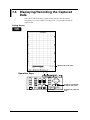
1st Edition
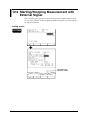
Foreword
Foreword
Thank you for purchasing the YOKOGAWA OR100E/OR300E. This User’s
Manual contains useful information about the instrument’s functions and operating
procedures as well as precautions that should be observed during use. To ensure
proper use of the instrument, please read this manual thoroughly before operating it.
Keep the manual in a safe place for quick reference whenever a question arises.
Notes
The contents of this manual are subject to change without prior notice as a result of
improvements in the instrument’s performance and functions. Display contents
illustrated in this manual may differ slightly from what actually appears on your
screen.
Every effort has been made in the preparation of this manual to ensure the accuracy
of its contents. However, should you have any questions or find any errors, please
contact your nearest YOKOGAWA representative listed on the back cover of this
manual.
Copying or reproduction of all or any part of the contents of this manual without
YOKOGAWA’s permission is strictly prohibited.
Trademarks
All company and product names used in this manual are trademarks or registered
trademarks of their respective companies.
Revisions
1st Edition: October 1999
Disk No. OR08
1st Edition : October 1999 (YK)
All Rights Reserved, Copyright © 1999 Yokogawa Electric Corporation
IM OR100E-01E
1
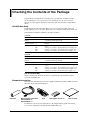
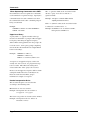
Checking the Contents of the Package
Unpack the box and check the contents before operating the instrument. If the
wrong instrument or accessories have been delivered, if some accessories are
missing or if they appear abnormal, contact the dealer from which you purchased
them.
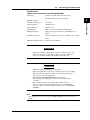
OR100E Main Body
Check that the model name and suffix code given on the name plate of the rear
panel match those on your order. Whenever you contact the dealer from which you
purchased the instrument, tell him your unit’s serial No.
OR100E
Model
OR122
OR142
Suffix Code
Specifications
2-channel isolated input model
4-channel isolated input model
Display language -2
English
Options
Carring case package.
code.
Carring case package.
Carring case package.
Carring case package.
/PM
/PF
/PR
/PS
UL/CSA standard power supply
VDA standard power supply code.
SAA standard power supply code.
BS standard power supply code.
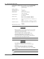
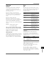
OR300E
Model
OR322
OR342
Suffix Code
Specifications
2-channel isolated input model
4-channel isolated input model
Display language -2
English
Options
Carring case package.
code.
Carring case package.
Carring case package.
Carring case package.
/PM
/PF
/PR
/PS
UL/CSA standard power supply
VDA standard power supply code.
SAA standard power supply code.
BS standard power supply code.
NO. (Instrument No.)
When contacting the dealer from which you purchased your instrument, please
quote the instrument No.
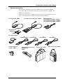
Standard Accessories
The following standard accessories are supplied with the instrument. Make sure that
all items are present and undamaged.
Roll chart
Measurement input cable
OR122,OR322 : 2
OR142,OR342 : 4
Belt
AAA allaline dry cell : 6
Users manual
In addition to the accessories listed above, AC adapter, battery pack and carrying
case are also included for models with the /PM suffix code.
2
IM OR100E-01E
Checking the Contents of the Package
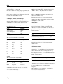
Optional Accessories
The following optional accessories are available. On receiving these optional
accessories, make sure that all the items that you ordered have been supplied and
that they are undamaged.
If you have any questions regarding optional accessories, or if you wish to place an
order, contact the dealer from whom you purchased the instrument.
4-ch logic plobe 788031
4-ch high voltage logic plobe 788035
DC/DC converter
9 to 18 VDC input model : 788025-1
18 to 36 VDC input model : 788025-2
36 to 60 VDC input model : 788025-3
logic plobe read
B9879PX
B9879KX
AC adapter 788011
-M
UL/CSA Standard
Temperature input
adapter 788041
IM OR100E-01E
-F
VDE Standard
Rechargeable battery pack
(NiMHbattery)
788021
-R
SAA Standard
Carring case 788081
-S
BS Standard
Small carring case 788082
3
Safety Precautions
This instrument is an IEC safety class II instrument (double insulation).
The following general safety precautions must be observed during all phases of
operation, service and repair of this instrument. If this instrument is used in a
manner not specified in this manual, the protection provided by this instrument may
be impaired. Also, YOKOGAWA Electric Corporation assumes no liability for the
customer’s failure to comply with these requirements.
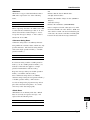
The following symbols are used on this instrument.
To avoid injury, death of personnel or damage to the instrument, the
operator must refer to an explanation in the User’s Manual or Service
Manual.
Function grounding terminal (This terminal should not be used as a
“Protective grounding terminal”.)
Direct current
ON(power)
OFF(power)
4
IM OR100E-01E
Safety Precautions
Make sure to comply with the following safety precautions. Not complying might
result in injury, death of personnel or damage to the instrument.
WARNING
Power Supply
Ensure the source voltage matches the voltage of the power supply
before turning ON the power.
Do not Operate in an Explosive Atmosphere
Do not operate the instrument in the presence of flammable liquids or
vapors. Operation of any electrical instrument in such an environment
constitutes a safety hazard.
Do not Remove any Covers
There are some areas with high voltages. Do not remove any cover if
the power supply is connected. The cover should be removed by
qualified personnel only.
IM OR100E-01E
5
How to Use This Manual
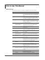
Manual Structure
This manual is divided into 14 chapters, an appendix and an index as follows.
Chapter Title
1
Overview
Description
Describes the functions of the OR100E, OR130 and its
parts. Reading this chapter helps you to understand the
operation procedures that are described in the following
chapters.
2
Before Operation
Describes handling precautions, installation of the
recorder, connection to the power supply, installation
and recharging of the batteries, power switch, loading of
the roll chart, setting of the date and time, and so on.
3
First-time Users
Describes the basic operations of the recorder.
Describes easy methods to set the measurement range,
sample rate, and trigger. Also describes how to display
or record the captured data.
4
Setting the Measurement Describes how to set the measurement conditions such
Range, Filter, Time Axis, as the measurement range, filter, and time axis. Also
and Linear Scaling
describes how to set the zero adjustment and linear
scaling. Describes the monitor screen.
5
Triggering
Describes how to set the normal trigger and the wave
window trigger.
6
Data Capturing
Describes how to capture the measured data to the
internal memory, display or record the captured data,
and read or calculate values using the cursor.
7
Realtime displaying and
Recording
Describes how to display and record the measurement
data in realtime.
8
Data Capturing while
Realtime Recording
Describes how to capture the data when a trigger
occurs while recording in realtime with the built-in
printer.
9
Performing Harmonic
Analysis
This function is only available on the OR300E.
Describes how to analyze the harmonic components on
the power supply.
10
Using External Media
Describes how to save measurement data and setup data
to the flash ATA memory card and how to load them.
Describes how to save the data to the flash ATA memory
card automatically after capturing the data.
11
Using Communication
Functions
Describes how to set the RS-232 and send waveforms
and digital values over the FAX modem. Describes how
to send the data automatically by FAX.
12
Miscellaneous Functions Describes how to operate multiple OR Series in
synchronization, hard copy, record list of setting
parameters, switch display language, set tags and
comments, and so on.
13
Troubleshooting,
Describes probable causes of problems and their
Maintenance, and Testing corrective measures. Describes the various messages
that appear on the screen. Also describes how to test the
recorder.
14
Specifications
Lists the functional specifications and general
specifications of the recorder.
Appendix
Describes the communication commands.
Index
6
IM OR100E-01E
How to Use This Manual
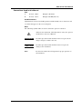
Conventions Used in this Manual
Unit
k
K
Denotes “1000”.
Denotes “1024”.
Example: 100 k data
Example: 640 KB (file size)
Used Characters
Alphanumerics enclosed in double quotation marks usually refer to characters and
set values that appear on the screen and panel.
Note
The following symbol marks are used to attract the operator’s attention.
Affixed to the instrument, indicating that for safety, the operator
should refer to the User’s Manual.
IM OR100E-01E
WARNING
Describes precautions that should be observed to prevent the
danger of injury or death to the user.
CAUTION
Describes precautions that should be observed to prevent
damage to the instrument.
Note
Provides information that is important for proper operation of
the instrument.
7
Contents
Foreword .................................................................................................................... 1
Checking the Contents of the Package ...................................................................... 2
Safety Precautions ..................................................................................................... 4
How to Use This Manual ............................................................................................ 6
Chapter 1 Overview
1.1
1.2
1.3
1.4
1.5
1.6
Chapter 2
2.1
2.2
2.3
2.4
2.5
2.6
Chapter 3
3.1
3.2
3.3
3.4
3.5
3.6
Chapter 4
4.1
4.2
4.3
4.4
4.5
4.6
4.7
Chapter 5
5.1
5.2
5.3
5.4
5.5
5.6
8
Names of the Parts and Their Functions ..................................................................... 1-1
System Configuration ................................................................................................. 1-4
Operation Mode .......................................................................................................... 1-6
Trigger Function ......................................................................................................... 1-7
Harmonic Analysis Function .................................................................................... 1-12
Input Method of Numerical Values and Characters .................................................. 1-13
Before Operation
Handling Precautions .................................................................................................. 2-1
Installing the Recorder ................................................................................................ 2-3
Connecting the Signal Cable ...................................................................................... 2-4
Connecting the Power Supply and ON/OFF ............................................................ 2-11
Loading the Chart ..................................................................................................... 2-20
Setting the Date and Time ......................................................................................... 2-23
First-time Users
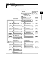
Setting Procedure ........................................................................................................ 3-1
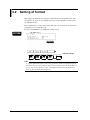
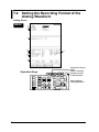
Setting of format ......................................................................................................... 3-2
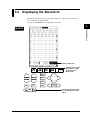
Displaying the Waveform ........................................................................................... 3-3
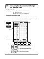
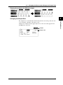
Changing the Measurement Range and Sample Rate ................................................. 3-4
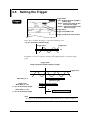
Setting the Trigger ...................................................................................................... 3-6
Displaying/Recording the Captured Data ................................................................... 3-7
Setting the Measurement Range, Filter, Time Axis, and Linear Scaling
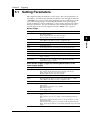
Setting Parameters ...................................................................................................... 4-1
Setting the Input Coupling .......................................................................................... 4-2
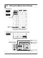
Setting the Measurement Range ................................................................................. 4-4
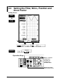
Setting the Filter, NULL, Position and Zoom Factor ................................................. 4-6
Setting the Time Axis (Sample Rate/Chart Speed) ..................................................... 4-8
Setting the Linear Scaling ......................................................................................... 4-10
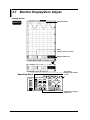
Monitor Display/Zero Adjust .................................................................................... 4-12
Triggering
Setting Parameters ...................................................................................................... 5-1
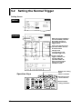
Setting the Normal Trigger ......................................................................................... 5-2
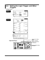
Setting the Logic Trigger, and Other Triggers ............................................................ 5-4
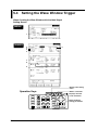
Setting the Wave Window Trigger .............................................................................. 5-6
Triggering with the Manual Trigger Key .................................................................. 5-10
Setting Trigger for Automatic Analysis of Harmonics ............................................. 5-12
IM OR100E-01E
Contents
Chapter 6
6.1
6.2
6.3
6.4
6.5
6.6
6.7
6.8
6.9
6.10
6.11
Chapter 7
7.1
7.2
7.3
7.4
7.5
7.6
Chapter 8
8.1
8.2
8.3
8.4
Chapter 9
9.1
9.2
9.3
9.4
9.5
9.6
9.7
9.8
9.9
9.10
Chapter 10
10.1
10.2
10.3
10.4
10.5
10.6
10.7
10.8
IM OR100E-01E
Data Capturing
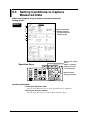
Setting Parameters ...................................................................................................... 6-1
Setting the Conditions on Capturing the Measurement Data ..................................... 6-2
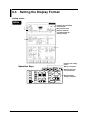
Setting the Display Format ......................................................................................... 6-6
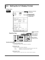
Setting the X-Y Display Format ................................................................................. 6-8
Starting/Stopping ........................................................................................................ 6-9
Displaying/Recording the Captured Data as an Analog Waveform ......................... 6-10
Recording the Captured Data as Digital Values ....................................................... 6-14
Zooming In or Out on the Displayed Waveform ...................................................... 6-16
Displaying the Cursor ............................................................................................... 6-18
Calculating Statistics ................................................................................................ 6-20
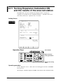
Turning Expansion Calculation ON and the results of the area calculation ............. 6-24
1
2
3
4
5
Realtime Displaying/Recording
Setting Parameters ...................................................................................................... 7-1
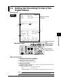
Setting the Recording Format of the Analog Waveform ............................................ 7-2
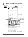
Setting the Recording Format of the Digital Values ................................................... 7-5
Setting the X-Y Recording Format ............................................................................. 7-6
Starting/Stopping ........................................................................................................ 7-7
Displaying/Recording the Captured Data ................................................................. 7-10
6
7
Data Capturing While Realtime Recording
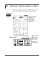
Setting Parameters ...................................................................................................... 8-1
Setting the “Realtime+Memory” Mode ...................................................................... 8-2
Starting/Stopping ........................................................................................................ 8-4
Displaying the Captured Data ..................................................................................... 8-5
8
9
Harmonic Analysis
Setting Parameters ...................................................................................................... 9-1
Connecting Cables for Power Measurement .............................................................. 9-3
Setting Conditions to Capture Measured Data ........................................................... 9-4
Setting the Display Format ......................................................................................... 9-9
Analyzing by Specifying the Range ......................................................................... 9-10
Analyzing Automatically .......................................................................................... 9-14
Saving the Results of the Analysis ............................................................................ 9-17
Recording the Results of the Analysis ...................................................................... 9-18
Other Functions ........................................................................................................ 9-19
Computing Equations for Harmonic Analysis .......................................................... 9-20
10
11
12
13
Using External Media
External Media .......................................................................................................... 10-1
Setting Parameters .................................................................................................... 10-3
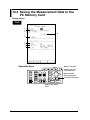
Saving the Measurement Data to the PC Memory Card ........................................... 10-4
Writing Data Simultaneously to the Flash ATA Memory Card .............................. 10-10
Loading the Measurement Data .............................................................................. 10-12
Displaying the Loaded Measurement Data ............................................................. 10-14
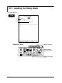
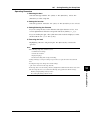
Loading the Setup Data .......................................................................................... 10-16
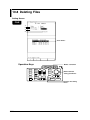
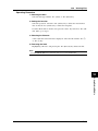
Deleting Files .......................................................................................................... 10-18
9
14
App
Index
Contents
Chapter 11
11.1
11.2
11.3
11.4
11.5
11.6
11.7
11.8
11.9
Chapter 12
Using Communication Functions
RS-232 Interface Specifications ............................................................................... 11-1
Connecting the RS-232 Interface Cable ................................................................... 11-2
Handshaking ............................................................................................................. 11-4
Matching the Data Format ........................................................................................ 11-7
Setting the RS-232 .................................................................................................... 11-8
FAX Modem ........................................................................................................... 11-10
Setting the FAX Modem ......................................................................................... 11-12
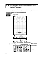
Sending the Measurement Data over the FAX Modem .......................................... 11-14
Other Fax Modem Functions .................................................................................. 11-18
Miscellanananeous Functions
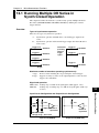
12.1 Running Multiple OR Series in Synchronized Operation ........................................ 12-1
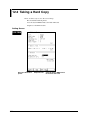
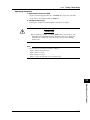
12.2 Taking a Hard Copy .................................................................................................. 12-4
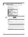
12.3 Capturing Data using the External Sampling Clock ................................................. 12-6
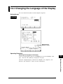
12.4 Changing the Language of the Display .................................................................... 12-7
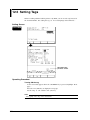
12.5 Setting Tags ............................................................................................................... 12-8
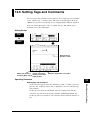
12.6 Setting Tags and Comments ..................................................................................... 12-9
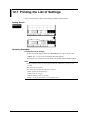
12.7 Printing the List of Settings .................................................................................... 12-10
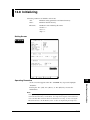
12.8 Initializing ............................................................................................................... 12-11
12.9 Starting/Stopping Measurement with External Signal ........................................... 12-12
12.10 Locking the Keys .................................................................................................... 12-14
12.11 Turning ON/OFF the Grid ...................................................................................... 12-16
12.12 Temporarily Changing the Width of the Wave Window Trigger ............................ 12-18
Chapter 13
13.1
13.2
13.3
13.4
Chapter 14
Troubleshooting, Maintenance, and Testing
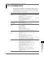
Troubleshooting ........................................................................................................ 13-1
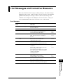
Messages and Corrective Measures .......................................................................... 13-3
Testing the Recorder ............................................................................................... 13-11
Cleaning the Printer Head ....................................................................................... 13-14
Specifications
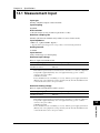
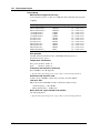
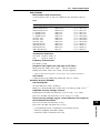
14.1 Measurement Input ................................................................................................... 14-1
14.2 Memory Function ..................................................................................................... 14-5
14.3 Recording .................................................................................................................. 14-6
14.4 Realtime Recorder & Memory ................................................................................. 14-8
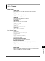
14.5 Trigger ...................................................................................................................... 14-9
14.6 Display .................................................................................................................... 14-10
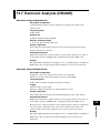
14.7 Harmonic Analysis (OR300E) ................................................................................ 14-11
14.8 Other Specifications ................................................................................................ 14-12
14.9 General Specifications ............................................................................................ 14-13
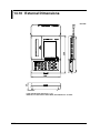
14.10 External Dimensions ............................................................................................... 14-16
Appendix
Appendix 1 Communication Commands ......................................................................... App-1
Index
Index ............................................................................................................................. Index-1
10
IM OR100E-01E
Chapter 1
Overview
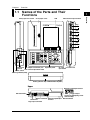
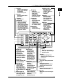
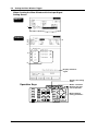
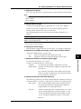
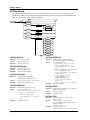
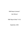
1.1 Names of the Parts and Their
Functions
Chart paper cover
Measurement input terminal
LCD
High
HANDY
OSCILLOGRAPHIC RECORDER
CH1
Low
High
CH2
Low
High
CH3
Low
High
CH4
Low
NEXT
FEED
MENU
PRINT
V/FS
POSITION
VARIABLE
PLAY
BACK
COPY
SYSTEM
MANUAL
TRIDDER
BACK
LIGHT
Functional
ground
TRIGGER
MONITOR
TIME
/DIV
AC adapter connection jack
LCD contrast adjustment knob
SCROLL
CURSOR
FILE
START
Operation panel
STOP
PC card PC card insert
eject button
Power switch
Recharge Monitor(LED)
Battery (Alkaline dry cell/Nickel-Metal Hydride)
Upper
Belt attachment
RS-232 connector External input/output
terminal
CH B CH A
Logic input connector
IM OR100E-01E
External input/output terminal
Trigger output
GND
Trigger input/Sampling clock/
Start and Stop
Belt attachment
1-1
Overview
Chart paper exit section
1
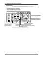
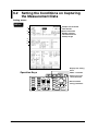
1.1
Names of the Parts and Their Functions
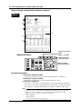
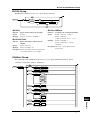
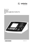
Operation Panel
The operation panel can be divided into the following groups of keys.
Keys dealing with setup of each channel
These keys deal with the setup parameters
that are individually set for each channel.
NEXT
FEED
MENU
PRINT
V/FS
POSITION
COPY
SYSTEM
MANUAL
TRIDDER
BACK
LIGHT
Keys used to set parameters
These keys are used to set
various parameters.
TRIGGER
PLAY
BACK
VARIABLE
MONITOR
Execution keys Monitor key
These keys execute
various operations.
TIME
/DIV
Keys for
setting the
time axis
SCROLL
CURSOR
FILE
START
Keys for moving the cursor
and scrolling the waveform
STOP
Start/Stop key of operation
Keys to display the setup screen
These keys display various setup screens.
Playback screen key
See next page for descriptions on the function of each
1-2
IM OR100E-01E
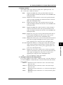
1.1
Names of the Parts and Their Functions
Copy key
Scroll/Cursor key
Valid on the
measurement range
setting screen
specified by the
channel key. Sets the
measurement range
Print key
Print the captured data in
the memory.
Select key
Selects the setting
item. Also used to
move along the digits
when inputting
numbers or characters.
Position key
Feed key
Feeds the chart.
Valid on the
measurement range
setting screen
specified by the
channel key. Changes
the waveform display
Channel key
Displays the screen for
setting the range/time
axis/filter/linear scaling.
On the display of captured
data, this key displays the
menu for turning ON/OFF
the waveform display and
scaling the waveform in the
voltage axis direction.
1
Moves the cursor or
scrolls the display
waveform. Also used
to select input
characters.
Range key
Overview
Output the data displayed
on the screen to the builtin printer/FAX
modem/memory card.
NEXT key
Displays the next
selectable item to be
displayed on the
screen. Valid when
" "is displayed on
the right of the
selectable items.
Setting keys
Sets the items
allocated to the keys.
NEXT
FEED
MENU
PRINT
V/FS
POSITION
COPY
SYSTEM
MANUAL
TRIDDER
BACK
LIGHT
Variable key
Valid on the
measurement range
setting screen
specified by the
channel key. Scales
the captured waveform
display in the voltage
(vertical) axis direction.
Monitor key
PLAY
BACK
VARIABLE
MONITOR
TIME
/DIV
Time axis key
Sets the time axis
(Time/div) on the
measurement range
setting screen
specified by the
channel key. At the
display of captured
data, this key scales
the waveform in the
time axis direction.
Monitors (Displays) the Playback key
measurement input.
Displays the captured
waveform.
Back light key
Displaying the
Turns the LCD back
cursor/specifying the
lighting ON/OFF.
block/calculating
Pressing this key for
statistics on an interval
three seconds locks or
can be performed.
unlocks the keys when
key lock function is set Menu key
ON.
Displays the screen to
Manual trigger key
set the conditions for
capturing measurement
Pressing this key sets
data/display
off the trigger when in
format/record format.
the trigger wait state.
IM OR100E-01E
TRIGGER
SCROLL
CURSOR
FILE
START
STOP
Stop key
Stops data capturing to the
memory or stops recording to
the built-in printer.
Start key
Starts data capturing to the
memory or starts recording to the
built-in printer.
Status indicator
Turns green during measurement.
File key
Displays the screen for
reading/writing the measurement
data/setup data to the PC card.
System key
Displays the screen for setting the
RS-232 or the FAX modem.
Trigger key
Displays the screen for setting the
trigger.
1-3
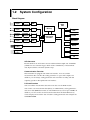
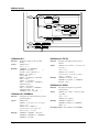
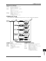
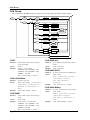
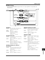
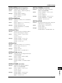
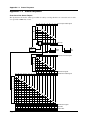
1.2 System Configuration
Block Diagram
Analog
Input
Photo
coupler
A/D
Analog
Input
Photo
coupler
A/D
Analog
Input
Photo
coupler
A/D
Photo
coupler
A/D
Analog
Input
32bit
RISC
CPU
Acquisition
Memory
LCD
Acquisition
Controler
Printer
Key Board
Logic
Probe
RS232
Logic
Probe
PC Card
External
I/O
A/D Converter
Each channel has an 11-bit A/D converter with maximum sample rate of 400 kS/s
(80 kS/s for wave window trigger) which ensures simultaneity of measurement
data, high resolution, and wide dynamic range.
Communication Function
This instrument is equipped with an RS-232 interface. You can send the
measurement data as well as the setting parameters to a personal computer. In
addition, you can change setting parameters and control the recording and data
capturing operations through the RS-232 interface.
PC Card Function
You can send the measurement data and screen data over the FAX modem.
You can also save measurement data (binary or ASCII format), setting parameters,
and screen data (BMP data format) to a flash ATA memory card of up to 40 MB. In
addition, you can read the saved measurement data from the flash ATA memory
card to display and record the data or load the setting parameters and configure the
OR100E/OR300E.
1-4
IM OR100E-01E
1.2
System Configuration
External Input/Output
You can input or output the following signals at the external input/output terminals
located on the upper panel.
Overview
External Trigger Output
This is the trigger signal output to other equipment.
External Trigger Input
This is the signal used to externally trigger this instrument.
You can use the external trigger input/output to operate up to four OR series
synchronously.
External Sampling Clock
You can input a clock in this terminal to externally control the sample rate when
capturing data.
Start/Stop Signal
This is an external signal used to start and atop the recorder.
IM OR100E-01E
1
1-5
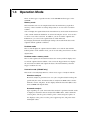
1.3 Operation Mode
There are three types of operation modes on the OR100E and four types on the
OR300E.
Memory mode
This instrument can save the sampled data in the internal memory (acquisition
memory). This is useful in recording changes that are too fast to be recorded in
realtime.
You can display the captured data in the internal memory and read the measurement
value or make statistical calculation on an interval using the cursors. You can also
zoom in or out on the waveform. In addition, you can record the captured data.
Furthermore, you can save the captured data to a flash ATA card.
By changing the time/div and data length settings, the measurement data can be
captured with the optimum conditions.
Realtime mode
The recorder displays the captured data in realtime or records the data with the
built-in printer. In the realtime mode, you can record analog waveforms as well as
digital values.
Realtime mode + memory mode
The recorder captures the measurement data to the memory while it displays and
records the captured data in realtime. You can use the trigger function to display
the waveform in realtime and capture the data to the internal memory when the
trigger conditions are met.
Harmonic mode (OR300E only)
This mode is for analyzing harmonics. There are two types of analysis methods.
Waveform analysis
Harmonic analysis is performed over one cycle of acquired data from the point
specified by the cursor. Parameters that are analyzed are RMS values, relative
harmonic content, and phase. It also displays harmonic distortion (IEC, CSA)
and total RMS with digital values.
Automatic analysis
Upon acquiring one cycle of measured data, analysis is performed and the result
is displayed. Parameters that are analyzed are RMS values, relative harmonic
content, phase, effective power, relative power content, and power phase. It
also displays active power, reactive power, apparent power, and power factor
with digital values.
1-6
IM OR100E-01E
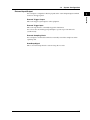
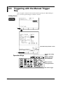
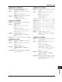
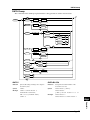
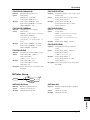
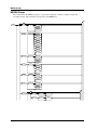
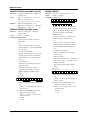
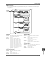
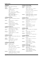
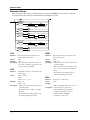
1.4 Trigger Function
1
Overview
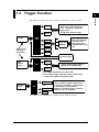
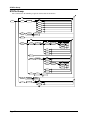
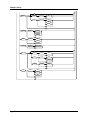
The following diagram shows the overview of the triggers of this recorder.
CH 1
to
CH 4
Normal
Trigger
AND/
OR
Trigger for the analog channels
Rise, fall, bi-slope, level (high,
low), window in, window out
Trigger filter***
Trigger filter, timeout trigger
CH A
CH B
Logic 4bit
AND/OR
Logic trigger
Rise, fall, level(high,
low), don't care
Logic trigger filter***
Common filter for all
bits
External
Select one of
the triggers
beforehand
Time*
Manual trigger
Wave
Window
Trigger**
CH 1
OR
to
Trigger for the analog channels
Specify wave window width
CH 4
* Time trigger valid only during "OR" mode
** Wave window trigger valid only during memory mode
*** Trigger filter valid during memory mode
Condition 1
Harmonic
Trigger
OR
to
Condition 4
Set up to 4 types of harmonic distortion
levels or relative harmonic content levels
for the trigger conditions. The parameter
for checking the levels(harmonic
distortion or relative harmonic content) is
common across all conditions.
Time
You cannot use the manual trigger while using the harmonic trigger.
IM OR100E-01E
1-7
1.4
Trigger Function
Triggering
You can set the following types of trigger conditions to trigger realtime recording
and data capturing.
Types
There are three major types of triggers.
Normal trigger (Edge trigger, level trigger, external signal, time)
Wave window trigger
Edge trigger/level trigger
Rise :
Trigger occurs when the trigger source signal changes from
below the predefined trigger level to above the trigger level.
Fall :
Trigger occurs when the trigger source signal changes from
above the predefined trigger level to below the trigger level.
High :
Trigger occurs when the trigger source signal is above the
predefined trigger level.
Low :
Trigger occurs when the trigger source signal is below the
predefined trigger level.
Bi-slope trigger : Trigger occurs when the trigger source signal changes from
below the predefined trigger level to above the trigger level or
from above the predefined level to below the trigger level.
Win-out :
Trigger occurs when the trigger source signal moves out of the
predefined region.
Win-in :
Trigger occurs when the trigger source signal enters the
predefined region.
Logic trigger :
You can select the following conditions on each bit: ignore(x),
changes from 0 to 1 (↑), changes from 1 to 0 (↓), is 1(1), and is 0
(0).
1-8
IM OR100E-01E
1.4
Trigger Function
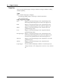
Trigger detected
Reference
signal for
the trigger
region
Trigger source
signal
Wave window
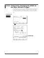
The width and the phase of the wave window can be specified for each channel.
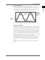
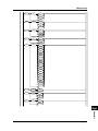
Synchronous Triggering
This instrument observes wave window trigger in units of one cycle. By doing this
repetitively, you can set triggers on consecutive signals. The trigger used to start
the one cycle trigger is called the synchronous trigger and the source channel used
to set off the synchronous trigger is called the synchronous trigger source channel.
You select the synchronous trigger source channel from one of the measurement
channels. When the measurement data of the synchronous trigger source channel
goes above a predefined level (Rise) or below the level (Fall), the synchronous
trigger is set off and starts the observation of the wave window trigger. Use a signal
with small distortion for the synchronous trigger source channel.
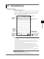
The example in the following figure shows the case when the synchronous trigger
type is set to Fall. Every time the synchronous trigger triggered, it starts the
observation of the wave window trigger as shown by the letters A, B, and C in the
figure.
The wave window trigger cannot be detected until the first synchronous trigger
occurs.
IM OR100E-01E
1-9
1
Overview
Wave Window Trigger
This is used to observe the 50-Hz, 60-Hz power supply signal. A wave window is
created based on the ideal power supply signal (sine wave) or an actual power
source signal (create a region by adding width on the reference signal). Trigger
occurs if the trigger source signal moves out of the wave window.
1.4
Trigger Function
Detected
Not detected
Trigger source
signal
Trigger level for
the synchronous
trigger
Measured signal of
the synchronous
trigger source
channel
B
C
A
Measurement
start
Synchronous Synchronous Synchronous Synchronous
trigger point trigger point trigger point trigger point
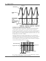
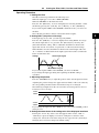
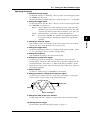
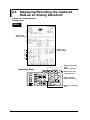
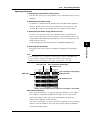
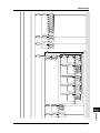
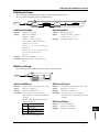
Conditions on Trigger Detection (Trigger Filter)
This feature can be used on normal triggers. The trigger occurs when the trigger
conditions (High condition for Rise, Low condition for Fall) are maintained
throughout the specified number of measurement counts. The actual trigger point is
located the specified count of points after the point at which the trigger condition is
first met. Below shows an example in which the measurement count is set to 3 and
the trigger type is set to “Rise” or “High.”
The trigger condition is met at point A, but the trigger is not set off because the
signal falls below the trigger level immediately afterwards. The trigger condition is
met again at point B. The trigger is set off at point C, because the signal stayed
above the trigger level for the specified number of three measurement counts(point
C) after point B (including point B as one count).
Trigger
detected
Measurement data
A
B
C
Trigger level
Trigger source signal
Trigger condition Trigger point
satisfied
Measurement period
For “↑” and “↓” of logic trigger, trigger does not occur until the trigger conditions
are met for the specified number of counts consecutively.
1-10
IM OR100E-01E
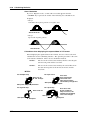
1.4
Trigger Function
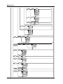
Sampling count 6
Sampling count 6
Trigger
detected
A
Measurement
data
Trigger source
signal
C
B
Trigger condition
satisfied
Trigger condition satisfied
Measurement period
Trigger
level
Trigger point
(Trigger condition
unsatisfied)
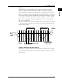
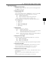
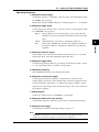
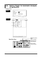
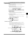
Trigger of Automatic Harmonic Analysis
This trigger is valid only during the automatic analysis in harmonic mode. Trigger
occurs when the harmonic distortion or the relative harmonic content exceeds the
specified level.
IM OR100E-01E
1-11
1
Overview
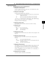
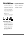
Timeout
Timeout can be set on normal triggers (edge trigger/level trigger). For edge
triggers, the trigger is set off, if the trigger condition is not detected within the
specified number of measurement counts after the first trigger detection. For level
triggers, if a trigger is not detected within the specified measurement count after the
first crossing of the trigger level after the detection of the previous trigger, a trigger
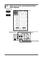
occurs. This is useful when observing how the level changes in a periodic signal.
Below shows an example in which the sampling count is set to 6 and the trigger
type is set to level trigger.
The trigger condition is met at point A and the data crosses the trigger level at point
B. Since the trigger condition is not met after 6 counts (point C) from point B, the
trigger occurs at point C.
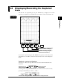
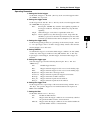
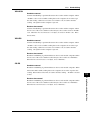
1.5 Harmonic Analysis Function
Measures the voltage and current of the power supply and performs harmonic
analysis. The results of the analysis are displayed with a bar graph or with digital
values.
There are two types of analyzing methods on this recorder.
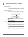
Specify the range and analyze
Harmonic analysis is performed over one cycle of acquired data from an arbitrary
point. This is useful when you wish to look over the waveform before performing
the analysis. The results can be saved to a file in CSV format.
Note
CSV files are data files which contain data separated by commas. These files can be
opened with spreadsheet applications.
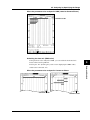
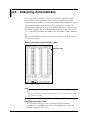
Analyze automatically
Upon acquiring one cycle of measured data, analysis is performed and the result is
displayed. This operation repeats automatically. The results can be saved to the
built-in PC card in ASCII format. Harmonic analysis on power can also be
performed.
1-12
IM OR100E-01E
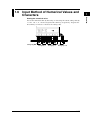
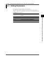
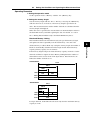
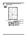
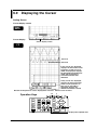
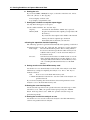
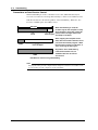
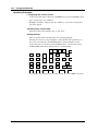
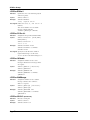
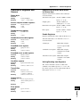
1.6 Input Method of Numerical Values and
Characters
NEXT
Change by -10
IM OR100E-01E
Change by -1
Change by +1
Change by +10
1-13
Overview
Setting the numerical value
You set the numerical value by increasing or decreasing the current setting value by
1 or 10. -10, -1, +1, +10 are assigned to F1 to F4 keys, respectively. You press the
F1 to F4 keys to increase or decrease the setting value.
1
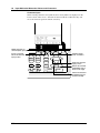
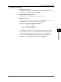
1.6
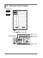
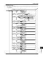
Input Method of Numerical Values and Characters
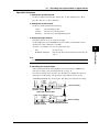
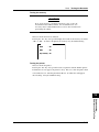
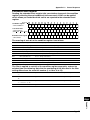
Character Input
When entering characters and symbols, letters and symbols are displayed on the
lower section of the screen. Select the character with the scroll/cursor key and
move the character position with the select key.
Deletes the previous
character (Back space)
NEXT
Inserts a character
before the character
input position
Switches upper/
lower case letters
MENU
V/FS
POSITION
TRIGGER
SYSTEM
PLAY
BACK
VARIABLE
TIME
/DIV
SCROLL
CURSOR
FILE
START
STOP
Moves the character
input position
Selects the character
(highlighted section
moves to the right)
Selects the character
(highlighted section
moves to the left)
1-14
IM OR100E-01E
Chapter 2
Before Operation
2.1 Handling Precautions
General Precautions on Handling
Display Screen
Remove the protective film covering the LCD after having set up the recorder. The
lifetime of the LCD is about 10,000 operating hours. Operation beyond this point
may cause the back lighting brightness to go down. In this case, you need to
replace the display. Contact your nearest YOKOGAWA dealer listed on the back
cover of this manual to have your LCD replaced.
Cleaning
Numerous plastic parts are used on this recorder. Use a dry, soft cloth for cleaning
the recorder. Do not use volatile chemicals such as benzene or thinner, as these
may cause discoloration or deformation.
Protecting the Case and Operation Panel
Do not apply volatile chemicals to the case or the operation panel. Do not allow
rubber or vinyl to remain in contact with the case or the operation panel for
extended periods of time. Doing so may cause damage to the recorder.
When Moving the Recorder
Ensure that the power cord and input cables are disconnected. Use both hands to
carry the recorder. Moving the recorder with the chart loaded may disturb the chart
setting. If you move the recorder with the chart loaded, check that the chart is
loaded properly by following the instructions in 2.5 “Loading the Chart”.
Unplug the power cord after Use
When the recorder is not used for a long time
If you are not going to use the recorder for a long time, remove the batteries (AAsize alkaline dry cell, NiMH battery) from the recorder.
Malfunction
Immediately stop the use of the recorder if there are any symptoms of malfunction
such as unusual sounds, smell, or smoke coming from the recorder. Turn OFF the
power switch and unplug the power cord. If you notice abnormal symptoms,
contact your nearest YOKOGAWA dealer listed on the back cover of this manual.
IM OR100E-01E
2-1
2
Before Operation
Input Terminals
Do not bring any objects charged with static electricity near the input terminals. It
may damage the internal circuit.
Do not apply shock to the input terminals. The shock may be converted to electric
noise and may enter the recorder.
2.1 Handling Precautions
Precautions on Handling the Printer Head
Printer Head’s Temperature
To protect the head, the printing load will automatically be reduced if the printer
head’s temperature exceeds a prescribed level. When the printer head’s temperature
goes back down, the print intensity will return to normal.
Dirty Printer Head
The printer head may become dirty over long periods of operation, causing the
printout to blur in some places. In this case, clean the printer head as described in
13.4 “Cleaning the Printer Head.”
Printer Head’s Life
The life of the printer head is about 50 km (about 5000 chart rolls). Operation
beyond this point may cause the print quality to go down. To replace the printer
head, contact your nearest YOKOGAWA dealer.
Power Save Printing
The printing density will automatically be reduced if the density gets too high. This
sometimes causes fainter recording.
2-2
IM OR100E-01E
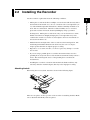
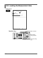
2.2 Installing the Recorder
Set the recorder in a place that meets the following conditions.
2
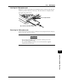
Attaching the belt
When using the accessory belt, attach it as shown in the following figure.
5
2
1
4
3
There are two places on the top section of the recorder for attaching the belt. Make
sure to attach the belt firmly at the two places.
IM OR100E-01E
2-3
Before Operation
• Placing the recorder under direct sunlight or near a heater will adversely affect
the internal circuit and the case. Choose a location near room temperature (23
˚C) with minimal temperature fluctuations. Relative humidity should be 35 to
80 % with no condensation. When the relative humidity is 35 % or below,
protect the recorder from static electricity buildup by using a grounded
discharge mat. Moving the recorder from a dry, cool environment to a warm,
humid environment or abruptly changing the room temperature may cause
condensation. In this case, let the recorder adjust to the new environment for
at least an hour before use.
• Maintain the left and right sides of the recorder near horizontal position. The
maximum permissible inclination from the front to the rear is ±5 degree.
Angles greater than this can impede proper recording.
• Exposure to soot, steam, moisture, or corrosive gases may damage or corrode
the recorder.
• If you are using a portable phone to send the measurement data, move the
portable phone away from the recorder and the measurement lead by at least a
meter. The electromagnetic waves of the portable phone can affect the
measurement.
• Installing the recorder in a location with mechanical vibration will not only
adversely affect the mechanical parts, but may cause improper recording.
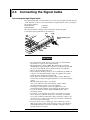
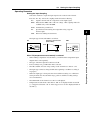
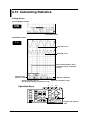
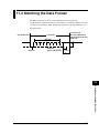
2.3 Connecting the Signal Cable
Connecting the Input Signal cable
The input signal cable for measurement is connected to the input terminals located
on the right side of the recorder. The number of input channels varies according to
the model as follows.
OR122/OR322 :
2 channels
OR142/OR342 :
4 channels
The input terminal is a bipolar safety terminal for the banana plug.
Connect the input signal cable as shown below.
Low
High
Measurement input
cable
CH2
CH3
CH4
WARNING
• To avoid electric shock, always use the accessory measurement
input cable to connect to the input terminals.
• Input impedance is about 1 MΩ. The signal source resistance
(including the input signal line resistance) should be less than 500
Ω. If it exceeds 500 Ω, a bias current of about 2 nA will flow.
Beware of the measurement errors.
• Never allow the floating voltage to exceed 500 Vrms (CAT II). If
voltages exceeding this floating voltage are applied to the input
terminal, it may damage the input circuit.
• Never allow the measurement input voltage (voltage difference
between the measurement input terminals) to exceed the following
values.
Measurement input voltage : ±250 Vrms
Also, never allow the sum of the floating voltage and the
measurement input voltage to exceed 250 Vrms.
If voltages exceeding these values are applied across the
measurement input terminal, it may damage the input circuit.
• Use an external sensor that comply with IEC1010-1, when
measuring current.
• For safety, use an external sensor that is enclosed in a case and
whose wires are isolated from the case. Also make sure that the
sensor has a sufficient withstand voltage against the voltage to be
measured. Use of a bare sensor may cause an electric shock if the
sensor is touched accidentally.
• If you are going to use a clamp-type sensor, make sure you are
fully aware of the voltage to be measured, sensor's specifications
and handling method, so that the possibility of dangers such as
electric shocks are avoided.
2-4
IM OR100E-01E
2.3
Connecting the Signal Cable
For Temperature Measurement
When using a type K thermocouple to measure temperature, you will need the
temperature input adapter (788041) that is sold separately.
Connect the thermocouple and the temperature input adapter in the following
fashion:
2
High
Before Operation
Low
+
Thermocouple
CH2
CH3
CH4
Temperature input adapter
788041
Use a thermocouple with a cross sectional area between 0.14 and 2.5 mm2.
CAUTION
Applying a voltage that exceeds the maximum input voltage (42 V
(DC+AC peak)) to the input terminal can damage the input circuit.
Note
The external sensor must be selected carefully and its frequency and phase characteristics
taken into account.
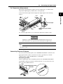
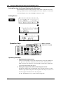
Connecting External I/O Signals
You can connect external signals to the “EXT INPUT/OUTPUT” terminal on the
upper panel of the recorder. To meet the recorder’s specifications, external
equipment must comply with IEC1010-1 or CSA1010.1.
Connecting the Wire
On the top panel, press the rectangular part above the “EXT INPUT/OUTPUT”
terminal with a minus screw driver and insert the wire. If you release the screw
driver, the wires will be fastened.
GND
TRIG IN/SAMPLING CLOCK
TRIG OUT
Wire
IM OR100E-01E
2-5
2.3
Connecting the Signal Cable
CAUTION
Applying voltage outside the allowable input voltage (-0.5 to 5.5 V)
to the input terminal may damage the input circuit.
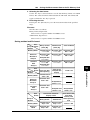
Wires
Recommended wire: solid wire ø1.0(AWG18), cross sectional area 0.75 mm2
Usable wires: solid wire ø0.4 to 1.0(AWG26 to 18), cross sectional area 0.3 to 0.75
mm2(AWG22 to 20), element wire at least ø0.18
Bare wire: 10 mm
External Trigger Input (Trig in)
Input a TTL-level trigger signal into this terminal. See page 11-6 for setting the
terminal. This terminal is also used when operating multiple OR100Es/OR300Es
synchronously. This terminal is shared with the external sampling clock or when
starting/stopping the recorder with external signals.
External Trigger Output (Trig out)
This terminal outputs a TTL-level trigger signal. This terminal is also used when
operating multiple OR100Es/OR300Es synchronously.
External Sampling Clock (Ext sample)
This terminal is used to input a TTL-level sampling clock. This terminal is shared
with the external trigger input.
Note
· Use cables that are 3 m or less to avoid erroneous operation due to noise.
· Separate the signal cables from power cords and cables that emit noise. Also, avoid
running the cables in parallel.
· To prevent an emission of electromagnetic disturbances, separate the external I/O wires
from the power supply and measurement input and logic input wires by at least 10 cm.
50 cm or more is recommended.
2-6
IM OR100E-01E
2.3
Connecting the Signal Cable
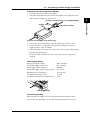
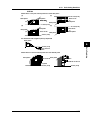
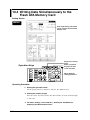
Connecting Logic Input Signals
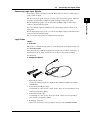
Logic Probe
788031
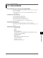
1. Overview
This probe is a dedicated logic probe for connecting to the logic input connector of
the OR100E/OR300E.
Since the probe has a TTL-level input/contact input selector switch, wide-range of
measurements can be made from electronic circuit to relay operation timing
measurements.
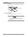
2. Component Names
4
1
2
3
1 Input selector switch :
Used to switch between the two input formats, TTL-level (TTL) and contact
(CONTACT).
2 Connection lead (alligator clip) :
Used mainly to connect to the contact circuit. There are four signal lines (red)
and four ground lines (black).
3 Connection lead (IC clip) :
Used mainly to connect to the electronic circuit. There are four signal lines
(red) and two ground lines (black).
4 Round-type connector :
This is for connecting to the logic input connector of the OR100E/OR300E.
IM OR100E-01E
2-7
2
Before Operation
Logic input consists of channels A and B. Each channel consists of 4 bits giving a
total of 8 bits of input.
The accessory logic probe is used to connect to the measurement points. There are
two types of logic input, normal logic probe and high-voltage logic probe.
For the normal logic probe, you can use either an alligator clip or an IC-clip to
connect to the measurement point.
You can select the input level, TTL level or contact input, with the switch on the
logic probe.
For the high-voltage logic probe, you can use the alligator-clip measurement lead to
connect to the measurement point.
The case and the logic probe are insulated from each other.
2.3
Connecting the Signal Cable
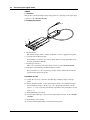
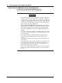
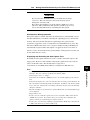
788035
1. Overview
This probe is a dedicated high-voltage logic probe for connecting to the logic input
connector of the OR100E/OR300E.
2. Component Names
3
1
2
4
1 Input indicator
The indicator lights when a voltage of 30 VDC or more is applied to the probe.
2 Connection lead (alligator clip) :
Used mainly to connect to the contact circuit. There are four signal lines (red)
and four ground lines (black).
3 Round-type connector :
This is for connecting to the logic input connector of the OR100E/OR300E.
4 Indication of the furthest point that should be touched
Never touch closer to the connection point beyond the indicated line while the
signal is being input to the probe.
Procedure on Use
(1) Attach the accessory connection lead (IC clip or alligator clip) to the logic
probe.
(2) When using the 788031, set the input selector switch. For a TTL-level input,
threshold input voltage is about 1.4 V : any voltage higher than this sets the
logic to “1.” For a contact input, shorting signal lines and ground lines sets the
logic to “1.”
(3) Turn OFF the power switch.
(4) Connect the round-type connector to the logic input connector of the OR100E/
OR300E.
(5) Turn ON the power switch.
(6) Connect individual lead clips to the measurement points.
2-8
IM OR100E-01E
2.3
Connecting the Signal Cable
WARNING
• Applying a floating voltage above 30 Vrms or 60 VDC may cause
electric shock. Never apply voltage above 30 Vrms or 60 VDC.
• The cover should be removed by qualified personnel only.
CAUTION
• Check the selector switch before connecting.
• The four input lines on a probe are common ground. Do not apply
different common voltages to them as it may damage the logic
probe or the connected equipment.
• Turn OFF the OR100E/OR300E when connecting or
disconnecting the round-type connector from the logic input
connector.
• Never modify (extend, for example) the connection leads.
• Do not exceed the allowable input range (± 35 V including the
common voltage). It may damage the logic probe or the OR100E/
OR300E.
Note
If the logic probe is not connected to the OR100E/OR300E, the waveform becomes “1”
(High).
IM OR100E-01E
2-9
2
Before Operation
Specifications
788031 (when connected to the OR100E/OR300E)
Input type :
Common ground within the same probe
Floating between recorder and probe
Number of inputs :
4
Allowable input range :
±35 VDC
Input impedance :
10 kΩ or more
Threshold level :
About +1.4 V
Input method :
TTL level or contact input (switching type)
Withstand voltage :
Between logic probe and case: 500 VDC for one
minute
Insulation resistance :
Between logic probe and case: 10 MΩ or more at 500
VDC
Maximum floating voltage : 30 Vrms AC or 60 VDC
2.3
Connecting the Signal Cable
Specifications 788035 (when connected to the OR100E/OR300E)
Input type :
Floating between recorder and probe
Isolated channels
Number of inputs :
4
Allowable input range :
± 250 Vrms
Input impedance :
100 kΩ or more
Detection level :
60 to 250 VAC (50/60 Hz)
±30 to ±250 VDC
Undetected level :
0 to 10 VAC (50/60 Hz)
0 to ±10 VDC
Response time :
Rise 1 ms or less (100 VDC, 200 VDC)
Fall 3 ms or less (100 VDC, 200 VDC)
Withstand voltage :
Between logic probe and case: 1.5 kVDC for one
minute
Between each channel: 1.5 kVAC for one minute
Insulation resistance :
Between logic probe and case: 10 MΩ or more at
500 VDC
Maximum floating voltage : 250 Vrms
WARNING
• Make sure that the measurement input voltage does not exceed the
value indicated below. If it exceeds the value, it may damage the
input section or cause electric shock.
Measurement input voltage: ±250 Vrms (CAT II)
Also, never allow the sum of the floating voltage and the
measurement input voltage to exceed 250 Vrms.
• High voltage is applied at the connection point of the probe.
Never touch closer to the connection point beyond the indicated
line while the signal is being input to the probe.
CAUTION
• Turn OFF the OR100E/OR300E when connecting or
disconnecting the round-type connector from the logic input
connector.
• Never modify (extend, for example) the connection leads.
Do not exceed the allowable input range (± V including the
common voltage). It may damage the logic probe or the OR100E/
OR300E.
Note
If the logic probe is not connected to the OR100E/OR300E, the waveform becomes “1”
(High).
2-10
IM OR100E-01E
2.4 Connecting the Power Supply and ON/
OFF
This recorder can use three types of power supplies:
• AAA Alkaline dry cell
• AC Power supply You need an AC adapter sold separately.
• Rechargeable battery You need a NiMH battery and an AC adapter for
recharging. Both are sold separately.
• DC Power supply You need a DC/DC converter sold separatery.
2
Before Operation
When using AAA Alkaline Batteries
Precaution on the Alkaline Dry Cell
CAUTION
• Place the batteries in the right direction. Otherwise, the batteries
may leak or explode.
• Do not disassemble, heat, or expose to fire.
• Do not short the batteries.
• Do not recharge the batteries.
• Do not solder onto the batteries.
• Do not use the manganese dry cell.
• Use new batteries from the same manufacturer.
• When replacing the batteries, replace all six.
• Remove the batteries if not used for long time.
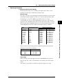
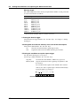
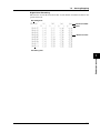
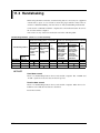
Operation time of alkaline dry cells
The operation time of alkaline dry cells depend on the environment and how it is
used. See the following table for a typical figure.
Condition
Operation Time
Trigger wait condition without options
About 2 hours (OR100E)
About 110 minutes (OR300E)
About 30 minutes (OR100E)
About 20 minutes (OR300E)
Recording an 1-Hz cycle waveform with 2 s/div setting
IM OR100E-01E
2-11
2.4
Connecting the Power Supply and ON/OFF
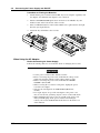
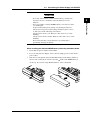
Procedure on Placing the Batteries
1 Check that the power switch is turned OFF. If you are using the separately sold
AC adapter, check that the AC adapter is not connected.
2 Turn the OR100E/OR300E upside down and remove the Alkaline dry cell
holder located on the bottom side of the recorder.
3 Place six Alkaline batteries in the holder. Make sure to place them in the right
direction (See figure below).
4 Attach the dry cell holder to the recorder.
When Using the AC Adapter
Before Connecting the Power Supply
Follow the warnings below to avoid electric shock or damaging the recorder.
WARNING
• Use the power cord that came with the recorder.
• Before connecting the power cord, check that the voltage on the
supply side matches with the voltage rating of this recorder.
• Before connecting the power cord, check that the OR100E/
OR300E is turned OFF.
• When not using the recorder for a long time, unplug the power
cord of the AC adapter.
• Only use the AC adapter from YOKOGAWA (Model No. :
788011).
• Do not put objects on top of the AC adapter or the power cord.
Also, do not let heat generating objects come in contact with them.
• When unplugging the power cord, do not pull on the power cord.
Always hold the plug. If the power cord becomes damaged,
contact your nearest YOKOGAWA dealer listed on the back cover
of this manual.
2-12
IM OR100E-01E
2.4
Connecting the Power Supply and ON/OFF
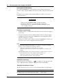
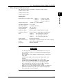
Procedures on Connecting the AC Adapter
1 Check that the power switch is turned OFF.
2 Attach the clamp filter that came with the AC adapter to the output side of the
cable of the AC adapter (see figure below).
DC output side (Connects to the OR100E/OR300E)
Before Operation
Approx. 10 cm
Clamp filter A1193MN
AC input side (Connects to the power plug)
3
4
5
Connect the optional AC adapter to the AC adapter jack on the recorder.
Connect the power cord plug that came with the AC adapter to the power
supply connector of the AC adapter.
Connect the plug on the other end of the power cord to a power outlet meeting
the following specifications.
The power outlet should be a three-pole type with a protective grounding
terminal.
Power Supply Rating
Rated power supply voltage :
Permissible supply voltage range :
Rated supply voltage frequency :
Permissible supply voltage frequency range :
Maximum power consumption :
AC adapter rated output voltage :
AC adapter maximum rated output current :
100 to 240 VAC
90 to 264 VAC
50/60 Hz
48 to 62 Hz
70 to 90 VAC
12 VDC
2.6 A
Function grounding
Functional grounding
When using the AC adapter, noise may be reduced if the functional ground is
connected to the earth GND. Use the functional ground terminal as necessary.
IM OR100E-01E
2
2-13
2.4
Connecting the Power Supply and ON/OFF
When Using the NiMH Battery Pack (Sold Separately)
Installation of the Dedicated NiMH Battery Pack
Follow the warnings below when using the NiMH battery.
WARNING
• The electrolyte solution inside the battery is alkaline. When the
solution comes in contact with clothing or skin due to a leakage or
an explosion, it may cause damage to the clothing or the skin. The
solution can cause blindness if it enters your eye. If the solution
enters your eye, run clean water on the eye. Do not wipe the eye.
Then, contact a physician immediately.
• When replacing the NiMH battery, turn OFF the power switch on
the front panel and unplug the AC adapter from the power outlet.
This will avoid accidents such as shorting the recharge circuit.
• Only use the NiMH battery pack from YOKOGAWA (Model No.
788021).
• Do not leave the battery under direct sunlight, inside a hot vehicle
or near fire. It may cause leakage or lower the performance and
life of the battery.
• Do not disassemble or modify the battery. It will damage the
protective device inside the battery and may cause heat and
explosion.
• Do not short the battery. The heat generated by the batteries may
cause burns.
• Do not throw the battery into fire. The battery may explode or the
electrolyte solution may spray out. This is very dangerous.
• Do not apply excessive shock such as throwing the battery. The
battery may leak, heat up, or explode.
• If you are moving the battery by itself, do not carry metal objects
such as paper clips together with the battery. You may short the
battery.
2-14
IM OR100E-01E
2.4
Connecting the Power Supply and ON/OFF
CAUTION
• Do not let water come in contact with the battery. It will cause
heat and corrosion. It will also cause the battery to lose its
function.
• It is not possible to recharge NiMH batteries once they have been
over discharged.
To prevent the battery from getting over discharged when not
using it for a long period, first recharge the battery, then remove
it, and store it in the following environment:
Storage for less than 1 year: Between -20°C and +35°C, at low
humidity.
Storage for less than 3 months: Between -20°C and +45°C, at low
humidity.
Even if stored in above environment it is recommended to
periodically recharge the battery.
2
Before Operation
When installing the dedicated NiMH battery, follow the procedure below.
1 Check that the power switch is turned OFF.
2 If you are using the AC adapter, remove the AC adapter power cord from the
power outlet.
3 Turn the recorder upside down and install the battery in the battery holder on
the near side of the bottom section so that the mark on the NiMH battery is
on the top. If you were using alkaline batteries, remove them first.
IM OR100E-01E
2-15
2.4
Connecting the Power Supply and ON/OFF
Recharging the NiMH battery
The dedicated NiMH battery (sold separately) is not recharged at the time of
purchase. When using the NiMH for the first time, fully recharge the battery before
use.
In addition, an AC adapter (sold separately, Model No. 788011) is necessary to
recharge the battery.
WARNING
• Always use the OR100E/OR300E to recharge the battery.
• Recharge the battery in an environment with a temperature
between +10 to +35 ˚C. Otherwise, the battery may leak , heat up
or not get fully recharged.
Procedure on Recharging
1 Install the battery as explained previously and connect the AC power supply to
the recorder.
2 If you leave the power switch to OFF, the LED on the side of the AC adapter
jack lights and starts recharging the NiMH battery. The LED blinks quickly
when the recharging is complete.
If the power switch is ON, it will not recharge the NiMH battery. In this case,
the power to the recorder is supplied from the AC adapter.
Note
· When the LED is blinking slowly (LED is on for about 1 s), recharge is on standby.
Recharge is put on standby for the following conditions.
If the battery temperature is outside +10 ˚C to 35 ˚C range.
If the battery performance has deteriorated drastically (from over discharge, for
example).
· The LED blinks rapidly to indicate that the recharge has completed. However, there are
cases when the battery may not be recharged as in the following cases.
If the battery temperature exceeded 55 ˚C while recharging.
If the environment temperature changes drastically.
Indication to Recharge
When the battery need recharging, a “
” is displayed on the upper left of the
screen. When this mark is displayed, recharge the batteries immediately.
Operation time between charges
Though it depends on how it is used. See the following table for a typical figure.
2-16
Condition
Operation Time
Trigger wait condition without options
Recording an 1-Hz cycle waveform with 2 s/div setting
About 3 hours and 30 minutes
About 3 hours
IM OR100E-01E
2.4
Connecting the Power Supply and ON/OFF
When Using the DC/DC converter
The following models are available for the different input voltages.
788025-1 For 12 VDC
788025-2 For 24 VDC
788025-3 For 48 VDC
2
WARNING
• Use the input cables provided by YOKOGAWA for the recorder.
• To avoid electric shock, never touch the input terminals while the
power is ON.
• To avoid electric shock, check the following before connecting the
input cable.
Check that the supply voltage matches the input voltage of the
recorder.
Check that the power on the supply side is turned OFF.
• Check that the OR100E/OR300E power switch is turned OFF
before connecting the output cable to the OR100E/OR300E.
• Do not put objects on top of the recorder or cables, or let heat
sources come in contact with the recorder or cables.
• Make sure to cover the terminals with the terminal cover during use.
• Tighten the terminal screws with a force of 0.8 N-m (8 kgf-cm).
Also, tighten the screws periodically.
IM OR100E-01E
2-17
Before Operation
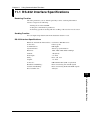
Specfication
Permissible power supply voltage : 788025-1
9 VDC to 18 VDC
788025-2
18 VDC to 36 VDC
788025-3
36 VDC to 60 VDC
Output voltage range : 12 VDC +/-5 % 20 VA MAX
Operating temperature : 5 ˚C to 40 ˚C
Operating humidity :
35 %RH to 80 %RH
Storage temperature : -20 ˚C to 60 ˚C
Storage humidity :
90 %RH or less
Withstand voltage :
Between input to output 500 VAC for 1min.
Insulation resistance :
Between input to output 100 M ohm 500 VDC.
Fuse :
788025-1
250 V timelag 6.3 A Ø5×20
788025-2
250 V timelag 4 A Ø5×20
788025-3
250 V timelag 4A (Ø5×20)
Input terminal :
Feed through terminal
External dimensions : About 68(W) × 26.2(H) × 167(D) mm (cable excluded)
Weight :
Approx 400 g (cable included)
Accessory:
Instruction Manual
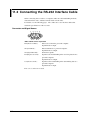
2.4
Connecting the Power Supply and ON/OFF
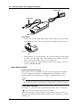
Output cable
Input cable
Input terminal
Connection
1. Connect the end of the input cable with the terminal chip to the input terminal
of the DC/DC converter. The center terminal of the input terminal is not used.
+
2. Check that there is no current flowing to the connection terminals on the supply
side, then connect the input cable to them. Make sure the polarities are correct
when connecting the DC/DC converter to the supply side.
3. Connect the power cord of the DC/DC converter to the AC adapter connection
jack of the OR100E/OR300E.
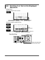
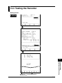
Power Switch ON/OFF
Before Turning ON the Power
This recorder can use AAA Alkaline dry cells, AC power supply (sold separately),
DC power supply (sold separately) or NiMH battery (sold separately). Before
turning ON the power, prepare the power supply as explained in the previous
sections.
Note
If you are using Alkaline dry cells or NiMH battery, remove the power cord and the AC
adapter. If the AC adapter is connected, the recorder will operate on the AC power supply.
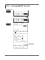
Power Switch Operation
Pressing the “ | ” side of the power switch turns the recorder “ON.” Pressing the
“ ” side of the power switch turns the recorder “OFF.”
When the power switch is turned ON, the recorder will run a self-test. Then, the
waveforms are displayed with the display conditions before the last time you turned
OFF the power.
2-18
IM OR100E-01E
2.4
Connecting the Power Supply and ON/OFF
Adjusting the Contrast
You can adjust the contrast of the screen by turning the knob beside the power
switch.
2
Before Operation
IM OR100E-01E
2-19
2.5 Loading the Chart
Follow the procedures below to load the roll chart. Have the power turned ON.
1. Slide the part indicated by a “ ” on the chart paper cover in the direction of the
arrow and open the cover.
2. Pull the release lever on the left side to a vertical position.
3. Bend the chart holder and load the chart paper in the direction as in the figure
(Load the right side as you face the printer, first).
4. Fold the front end of the roll chart back about 10 mm in the direction as in the
figure.
5. Rotate the roll chart in the direction as in the figure. Stop when the front end of
the chart reaches the chart slot.
6. After rotating the roll chart by a small amount in the opposite direction as in
step 5, press the “FEED” key to feed the chart until about 80 mm is showing
from the chart paper exit section. Then, adjust it so that the section of the paper
that is showing is aligned with the roll chart.
7. After pressing the release lever down firmly to the original position, slide the
front end of the chart through the chart guide of the chart paper cover. Then,
while gently pulling on the chart showing at the front of the product, close the
chart paper cover.
8. Press the “FEED” key and check that the paper feeds properly.
Note
· The last meter of the chart has a red band to notify you that it is time to replace the chart.
· When cutting the chart paper, pull up slowly on the section of the chart to cut.
· Do not tear the record chart at the thermal head section as paper dust will enter the printer
section and cause blurs in printing.
· When using the small carrying case, make sure that the chart paper is showing on the
outside of the case. Otherwise, the chart may not feed properly.
2-20
IM OR100E-01E
2.5
Loading the Chart
2
Chart holder
Before Operation
Release
lever
Chart holder
Approx. 10 mm
Approx.
80 mm
Roll chart
Printer cover
Chart guide
FEED key
Chart slot
IM OR100E-01E
2-21
2.5
Loading the Chart
Precautions on Handling the Charts
Storing Chart Paper
The thermal paper changes color at about 70 ˚C. Since it is affected by heat,
humidity, light, and chemicals regardless of whether or not the paper has been used,
beware of the following points.
· Store the chart in a cool, dry, dark place.
· After breaking the seal, use the chart paper quickly.
· Prolonged contact with plastic films which contain plasticizer (vinyl chloride
film, cellophane tape and so on) can cause fading. Therefore, if the paper is to
be stored in a folder, use a polypropylene type folder.
· Do not use glue which contain organic solvents such as alcohol and ether on the
chart paper as this will cause discoloration.
· For long term storage, taking photocopies of the charts is recommended.
Thermal paper has a tendency to fade.
Using Chart Paper
· Only use chart paper provided by YOKOGAWA. Using other charts may cause
paper jam.
· Use dry hands when touching the chart. Perspiration from the hand can cause
smudging.
· Do not rub the surface with hard objects. Heat generated from friction may
cause discoloration.
· Avoid contact with chemicals, oils, and other substances. It may cause
discoloration and fading.
2-22
IM OR100E-01E
2.6 Setting the Date and Time
Setting Screen
2
SYSTEM
Before Operation
1
2
Display the
setting screen
Operation Key
NEXT
FEED
PRINT
V/FS
POSITION
COPY
TRIGGER
Move between
setting parameters
SYSTEM
MANUAL
TRIDDER
BACK
LIGHT
Making selections
MENU
PLAY
BACK
VARIABLE
MONITOR
TIME
/DIV
SCROLL
CURSOR
FILE
START
STOP
Operating Procedure
1. Setting the date and time
Use the “F1” to “F4” keys to set the data and time. Date is specified in year/
month/day order and the time is specified in hour/minute/second order.
2. Confirming the setting
If you highlight “Set”, “Confirm” and “Cancel” will be displayed on the “F1”
and “F2” keys, respectively. Confirm the setting by pressing “F1.”
IM OR100E-01E
2-23
Chapter 3
First-time Users
3.1 Setting Procedure
The following figure shows the flow of a standard OR100E/OR300E operation and
the corresponding keys to display the setting screen.
Operation
Keys to display the
setting screen
Set measurement conditions
CH1
to
CH4
Set the trigger
“Harmonic” mode
TRIGGER
“Realtime” mode/”
Realtime+memory” mode
Set the operation mode and
the conditions for capturing data
MENU
MENU
Set the display format
Set the display format
MENU
MENU
Set the recording format
Start measurement
START
START
Start measurement
Stop measurement
STOP
STOP
Stop measurement
Display captured data
PLAY
BACK
Select the block
PLAY
BACK
Display captured data
Set the recording format
MENU
Start recording captured data
PLAY
BACK
Select the block
PLAY
BACK
Start recording captured data
Only in “Realtime+Memory” mode
Waveform analysis
Automatic analysis
MENU
Set the display format
Start measurement
START
Start measurement
Display the result of analysis
STOP
Stop measurement
Stop measurement
PLAY
BACK
START
STOP
Display captured data
Select the block
Waveform analysis
IM OR100E-01E
3-1
First-time Users
Measurement range
DC (V/div)
TC (200 °C/400 °C/600 °C)
Time/div
3
3.2 Setting of format
This chapter describes how to change the functions that are frequently used. The
descriptions are given on an assumption that you are operating the recorder from
the initialized state.
First, initialize the recorder. If this is the first time you are using the recorder after
purchasing, you can skip this step.
Press the “SYSTEM” key to display the setting screen.
SYSTEM
Initialize settings
NEXT
Note
A complete initialization will reset the setting parameters and the measurement data in the
internal memory. Save the setting parameters and measurement data to the flash ATA card
as necessary. To save the data, see 10.3 “Saving Measurement Data to the PC Memory
Card” or 10.5 “Saving/Loading Setup Data.”
3-2
IM OR100E-01E
3.3 Displaying the Waveform
Input the measurement signal to the input terminal according to the procedures in
2.3 “Connecting the Signal Cable.”
Pressing the “MONITOR” key displays the waveform.
3
MONITOR
First-time Users
Display update rate
NEXT
Automatically set the
measurement range
according to the
input signal
MENU
V/FS
POSITION
TRIGGER
SYSTEM
PLAY
BACK
VARIABLE
TIME
/DIV
IM OR100E-01E
FILE
SCROLL
CURSOR
Change the display update
rate according to the inpu
signal
3-3
3.4 Changing the Measurement Range
and Sample Rate
Setting the Input Type
Set the input type according to the item being measured.
DC: DC voltage
TC: Type K thermocouple
RMS: Rms value of the AC voltage (OR300E only)
Changing the Measurement Range
Changing the measurement range changes the full scale and the amplitude of the
displayed waveform.
Select the channel you wish to change by pressing the corresponding “F1” to “F4”
key. A screen for setting the measurement range is displayed.
time/div
CH 1
to
CH 4
Full scale
Measurement range
NEXT
Increase the measurement range
(waveform amplitude becomes smaller)
V/FS
POSITION
Decrease the measurement range
(waveform amplitude becomes larger)
PLAY
BACK
VARIABLE
TIME
/DIV
3-4
Set the time axis (time/div)
IM OR100E-01E
3.4
Changing the Measurement Range and Sample Rate
Displayed waveforms for different ranges
3
Changing the Sample Rate
time/div
Sample rate
IM OR100E-01E
3-5
First-time Users
The sample rate is automatically determined by the time axis setting. The time axis
is set in time/div. Time/div is the time in 1 div.
Sample rate is displayed in the upper right corner of the screen that appears when
the MENU key is pressed.
3.5 Setting the Trigger
Trigger mode
Free : Capture the data regardless
of the trigger
Single : Capture one block of data
once after the trigger
Repeat : Capture one block of data
after every trigger
Trigger delay
Trigger
Trigger using AND or OR
Trigger condition for each channel
In the above example, the trigger occurs in the following cases.
2 V (10% of the measurement range)
Trigger point
Trigger level
0V
In addition, you can set a delay to start the data capturing before or after the trigger
point.
Trigger point
Range captured to memory (Memory length)
Trigger level
Range captured to memory
(Memory length)
When delay is 0
Trigger level
When delay is -10%
x = 10% of the memory length
When delay is +10%
x = 10% of the memory length
Range captured to memory
X
X
Range captured to memory
Note
If a trigger is set, measurement data is not captured until the trigger condition is satisfied.
3-6
IM OR100E-01E
3.6 Displaying/Recording the Captured
Data
The data that was captured by pressing the “START” key, is displayed or recorded.
Pressing the “Playback” key displays the current block of the measurement data.
PLAYBACK
3
First-time Users
NEXT
Displays the calculation screen
Selects the block to display
Displays the cursor screen
Sets the recording range and
executes the recording
To record the capture data, press the “PRINT” key or press the “F1” key on the
Playback screen. It will record the measurement data of the current displayed
block.
Zooming in or out on the Waveform
Pressing the “Time axis” key will zoom in on the waveform in the time axis
direction.
Zoom out in the
time axis direction
TIME
/DIV
Zoom in the time
axis direction
Zooming in the voltage axis direction is done in the waveform scale screen by
pressing the channel keys (“CH1” to “CH4”).
Zoom in the voltage direction
IM OR100E-01E
Zoom out in the voltage direction
3-7
Chapter 4
Setting the Measurement Range, Filter, Time Axis, and Linear Scaling
4.1 Setting Parameters
The parameters shown below will be set in this chapter.
You will set these parameters using the screen that is displayed by pressing the
“CH1” to “CH4” keys. Zero adjustment is done at the screen that appears when the
“MONITOR” key is pressed.
Description
Input type
Select temperature measurement using thermocouple, DC voltage,
or ground.
Set the measurement range in V/div with the “RANGE” key.
Select either DC input or ground level.
Set ON/OFF using the “F2” key
Take the current input value to be 0.
Set the time/div with the time axis TIME/DIV key.
Linear scale to another physical value
Adjust the ground level to zero.
Measurement range
Input coupling
Filter
NULL
Time axis
Scaling
Zero adjust
IM OR100E-01E
4-1
4
Setting the Measurement Range, Filter, Time Axis, and Linear Scaling
Setting parameters
4.2 Setting the Input Coupling
Setting Screen
CH 1
to
CH 4
Displays the setting
menu
Operation Keys
NEXT
FEED
MENU
PRINT
V/FS
POSITION
VARIABLE
PLAY
BACK
COPY
TRIGGER
SYSTEM
MANUAL
TRIDDER
BACK
LIGHT
Sets the measurement
range
Makes a selection
MONITOR
TIME
/DIV
SCROLL
CURSOR
FILE
START
STOP
Displays the monitor
screen
4-2
IM OR100E-01E
4.2
Setting the Input Coupling
Operating Procedure
Setting the Input Coupling
Selects the method to couple the input signal to the vertical control circuit.
Press the “F1” key. Select the coupling method from the following.
DC : Captures the DC and AC components of the input signal.
RMS : Measures the RMS value of the AC voltage. This coupling method is
available only on the OR300E.
GND : Confirms the ground level.
TC:
Specified when measuring the temperature using a type K
thermocouple.
OFF : When not making measurements.
Frequency characteristics
(without filter)
DC
Gain
1MΩ
H
GND
-3dB
Input
circuit
H
Input
circuit
L
L
DC
40kHz
When TC (temperature measurement) is selected
• When making temperature measurements, you will need the temperature input
•
•
•
•
•
•
•
IM OR100E-01E
adapter that is sold separately.
The type of thermocouple that can be used is K.
Linear scaling is not possible when TC is selected.
The filter, NULL, and auto range settings of the channel set to TC are void.
The input type cannot be changed while data capturing or realtime recording is
in progress.
When the input type is changed to TC from a different setting or to a different
setting from TC, the measurement range, position, and linear scaling settings
are not maintained.
The GND mark of the channel set to TC is not displayed.
Temperature measurement values below -100 °C are displayed with an asterisk
(*). Trigger levels below -50 °C on the trigger screen are also displayed with an
asterisk (*).
4-3
Setting the Measurement Range, Filter, Time Axis, and Linear Scaling
The input type for DC and GND is as follows.
4
4.3 Setting the Measurement Range
Setting Screen
CH 1
to
CH 4
Full scale
Measurement
range
Setting the Measurement Range Automatically (Auto range)
Monitor
Displays the setting
menu
Operation Keys
NEXT
FEED
MENU
PRINT
V/FS
POSITION
VARIABLE
PLAY
BACK
COPY
TRIGGER
SYSTEM
MANUAL
TRIDDER
BACK
LIGHT
Sets the measurement
range
Makes a selection
MONITOR
TIME
/DIV
SCROLL
CURSOR
FILE
START
STOP
Displays the monitor
screen
4-4
IM OR100E-01E
4.3
Setting the Measurement Range
Operating Procedure
V/div
Measurement range
10 mV/DIV
20 mV/DIV
50 mV/DIV
0.1 V/DIV
0.2 V/DIV
0.5 V/DIV
1 V/DIV
2 V/DIV
5 V/DIV
10 V/DIV
20 V/DIV
50 V/DIV
100 V/DIV
100 mV
200 mV
500 mV
1V
2V
5V
10 V
20 V
50 V
100 V
200 V
500 V
1000 V
Acrual measurement
DC
RMS
±100.0 mV
0 to 100.0 mVrms
±200.0 mV
0 to 200.0 mVrms
±500.0 mV
0 to 500.0 mVrms
±1.000 V
0 to 1.000 Vrms
±2.000 V
0 to 2.000 Vrms
±5.000 V
0 to 5.000 Vrms
±10.00 V
0 to 10.00 Vrms
±20.00 V
0 to 20.00 Vrms
±50.00 V
0 to 50.00 Vrms
±100.0 V
0 to 100.0 Vrms
±200.0 V
0 to 200.0 Vrms
±500.0 V
0 to 500.0 Vrms
±500.0 V
0 to 500.0 Vrms
The measurement range setting and the actual measurement range when the
input type is set to TC are as follows:
Measurement range Acrual measurement
200°C
-50 to 200°C
400°C
-50 to 400°C
600°C
-50 to 600°C
Auto range
This is set at the screen that appears when the “MONITOR” key is pressed.
Press the “F2” key. V/div is automatically set according to the current input
signal.
Auto range is not possible on channels for which the input is set to TC.
IM OR100E-01E
4-5
4
Setting the Measurement Range, Filter, Time Axis, and Linear Scaling
1. Setting the Measurement Range
The measurement range is set according to the input signal. There are two
methods to set the range, manual range and auto range.
Manual range
The range is set at the screen that appears when the channel key is pressed. The
current input signal is displayed on the screen. The measurement range when
the input type is set to DC or RMS is specified in terms of a voltage
corresponding to 1 division of the grid displayed on the screen. Pressing the
upper part of the “RANGE” button increases the measurement range. Pressing
the lower part of the “RANGE” button decreases the measurement range. The
relationship between the V/div and the measurement range is as follows.
4.4 Setting the Filter, NULL, Position and
Zoom Factor
Setting Screen
CH 1
to
CH 4
1
2
VARIABLE
4
Operation Keys
NEXT
FEED
MENU
PRINT
V/FS
POSITION
VARIABLE
PLAY
BACK
COPY
SYSTEM
MANUAL
TRIDDER
BACK
LIGHT
TRIGGER
MONITOR
TIME
/DIV
SCROLL
CURSOR
FILE
START
Makes a selection
3 Moves the
waveform up
3 Moves the
waveform down
STOP
Displays the zoom
factor setting screen
4-6
IM OR100E-01E
4.4
Setting the Filter, NULL, Position and Zoom Factor
Operating Procedure
Voltage
Actual input signal
Measurement signal
If you set the input to RMS on the OR300E, you cannot set NULL.
If you change the input type during data capturing, the NULL setting is
cancelled.
3. Adjusting the position
Press the “POSITION” key to adjust the position of the current input waveform.
Adjusting the position changes the upper and lower limits of the scale values by
the corresponding amount, but the measurement range is not changed.
The following example shows the case when the waveform position is moved
lower by 0.5 V at 5 V range.
Display range
Measurement
range
5.50 V
5.00 V
- 4.50 V
- 5.00 V
If you change the input from DC to RMS or vice versa on the OR300E, position
setting is reset.
4. Setting the zoom factor of the voltage axis of the displayed waveform
Pressing the “Zoom” key at the screen that appears when one the “CH1” to
“CH4” keys is pressed, displays a screen for setting the zoom factor of the
voltage axis. Select the zoom factor using the “F2” (up) and “F3” (down) keys.
Changing the zoom factor changes the V/DIV setting.
IM OR100E-01E
4-7
4
Setting the Measurement Range, Filter, Time Axis, and Linear Scaling
1. Setting the Filter
The filter cannot be specified for the following cases:
When the input type is set to TC or RMS (OR300E).
When the OR300E is in the harmonic mode.
Press the “F2” (Filter) key. A screen is displayed for selecting the filter. Select
the filter by pressing “F1” (Off) key, “F2” (5 Hz) key, or “F3” (500 Hz) key.
If you set the input to RMS on the OR300E or harmonic mode, you cannot set
the filter.
The 5-Hz low-pass filter is always activated for thermocouples.
2. Setting NULL (only when necessary)
If the input type is set to TC, you cannot specify NULL.
Press the “F3” (Null) key. A screen is displayed for setting NULL. To assign
the current input value to “0,” press the “F2” (Execute) key. Pressing “F1”
(Off) will cancel the setting. This is valid when the difference between the
input value and “0” is less than or equal to 10 % of the measurement range.
When NULL is executed, the difference between the current input value and
“0” is added to or subtracted from the input signal. The result is considered to
be the measurement data.
4.5 Setting the Time Axis (Sample Rate/
Chart Speed)
Setting Screen
time/div
CH 1
to
CH 4
Displays the setting
menu
Operation Keys
NEXT
FEED
MENU
PRINT
V/FS
POSITION
VARIABLE
PLAY
BACK
COPY
SYSTEM
MANUAL
TRIDDER
BACK
LIGHT
TRIGGER
MONITOR
TIME
/DIV
SCROLL
CURSOR
FILE
START
STOP
Decreases the time/div
Increases the time/div
4-8
IM OR100E-01E
4.5
Setting the Time Axis (Sample Rate/Chart Speed)
Operating Procedure
Setting the time axis
The time axis is set in terms of the time with respect to 1 div. Press the “time
axis” key at the measurement range setting screen that appears when the one of
the “CH1” to “CH4” keys is pressed. Pressing the right side of the key
decreases the time/div (sample rate/chart speed are increased). Pressing the left
side of the key increases the time/div (sample rate/chart speed are decreased).
The time axis setting in the harmonic mode is determined automatically from
the frequency of the target waveform.
Relationship between Time/Div and Sample Rate
In the “Memory” mode or the “Realtime+Memory” mode, the recorder captures
80 measurement data per 1 div. By setting the time/div, the sample rate (the
number times the data is captured in 1 s) is automatically determined.
Sample rate = 80 / (time/div) The unit of time/div is seconds.
Relationship between Time/Div and Chart Speed
In the “Realtime recording” mode, data is recorded by considering 1 div to be
10 mm. The following table shows the relationship.
IM OR100E-01E
time/div
Chart speed
2 s/div
5 s/div
10 s/div
30 s/div
1 min/div
2 min/div
5 min/div
10 min/div
30 min/div
1 hour/div
5 mm/s
2 mm/s
1 mm/s
20 mm/min
10 mm/min
5 mm/min
2 mm/min
1 mm/min
20 mm/hour
10 mm/hour
4-9
4
Setting the Measurement Range, Filter, Time Axis, and Linear Scaling
Note
· The time axis can be set on the following screens.
Screen that appears when one of the “CH1” to “CH4” keys is pressed.
Screen that appears when the “MENU” key is pressed.
Screen that appears when the “TRIGGER” key is pressed.
· If you press the “time axis” key on the playback screen it will zoom in or out on the
waveform. Sample rate does not change.
· The range for setting the time/div varies depending on the measurement mode.
When the measurement mode is “Memory” or “Memory & Realtime”: 200 µs to 2
min.
When the measurement mode is “Realtime”: 2 s to 1 hour.
· Changing the time/div at the screen that appears when one of the “CH1” to “CH4” keys
is pressed, does not change the waveform that is displayed on the screen. The
waveform displayed on the screen changes depending on the display update rate, which
is located at the screen that appears when the “MONITOR” key is pressed.
· External is set when using an external sampling clock.
· When using wave window trigger, select the time axis from 1 ms/div, 2 ms/div, 5 ms/
div, or 10 ms/div.
4.6 Setting the Linear Scaling
Setting Screen
CH 1
to
CH 4
1
2
3
4
5
Go back to the previous screen
Displays the setting
menu
Operation Keys
NEXT
FEED
MENU
PRINT
V/FS
POSITION
VARIABLE
PLAY
BACK
COPY
SYSTEM
MANUAL
TRIDDER
BACK
LIGHT
4-10
TRIGGER
MONITOR
TIME
/DIV
SCROLL
CURSOR
FILE
START
STOP
Makes a selection
Moves between
setting parameters
Moves the input position when
entering characters/numerical
values
Selects the character or
numerical value when
entering characters/numerical
values
IM OR100E-01E
4.6
Setting the Linear Scaling
Operating Procedure
Scale value
Point 2
y=ax+b
Point 1
Point 1
Point 2
Voltage value
Enter the voltage value (measured value) at Point1 and the corresponding
physical value. There are two ways to enter the voltage.
Entering the value directly
Use the panel keys to enter the value.
Entering the current input voltage as the voltage value
Press the “F3” (Measure) key to enter the current input signal value.
If you selected 751550 in step 2, the scale value matching the output of
YOKOGAWA 751550 (clamp probe) is entered.
After entering the voltage value and the physical value, press the “F4”
(Enter) key.
Sets the current input
signal to the voltage value
Confirms the setting
Note
· The ranges for setting the voltage value and the scaling value are as follows.
-1.0×10+9 < × < -1.0×10⁻⁹, 0, 1.0×10⁻⁹ < × < 1.0×10+9
· Set exponential representation using E.
1.0E + 8 = 1.0×10+8
· Linear scaling is not possible when the input type is set to TC.
5. Setting Point2 (P2)
Enter the values in the similar way as entering the values for Point1.
IM OR100E-01E
4-11
4
Setting the Measurement Range, Filter, Time Axis, and Linear Scaling
1. Displaying the linear scaling setting screen
Press the “F4” (Scaling & Comm.) key.
2. Setting ON/OFF
Press the “F2” (On) key or the “F3” (751550) key (when using YOKOGAWA
751550 (OR300E only, scheduled release)) to perform linear scaling. Press the
“F1” (Off) key not to perform linear scaling.
3. Setting the unit.
Set the unit with six characters or less.
4. Setting Point1 (P1)
As shown in the figure below, by setting scale values to the two arbitrary
measured voltages, the scale converting equation (y=ax+b) is determined.
4.7 Monitor Display/Zero Adjust
Setting Screen
Operation mode
MONITOR
V/DIV
(voltage value per 1 DIV)
Display update rate
Zero adjust
Displays the monitor
screen
Operation Keys
NEXT
FEED
MENU
PRINT
V/FS
POSITION
VARIABLE
PLAY
BACK
COPY
TRIGGER
SYSTEM
MANUAL
TRIDDER
BACK
LIGHT
3
MONITOR
TIME
/DIV
SCROLL
CURSOR
FILE
START
STOP
Changes the display
update rate
4-12
IM OR100E-01E
4.7
Monitor Display/Zero Adjust
Operating Procedure
1. Monitor displaying
Pressing the “MONITOR” key, sets the screen to the monitor display screen.
The current input can be confirmed on the screen. The data is not saved.
Switching between the analog waveform display and digital value
display
Pressing the “MONITOR” key again in the monitor display screen switches the
analog waveform display and the digital value display.
4
Analog channel
When input is OFF
Bit No.
Logic channel A
Logic channel B
2. Pause the waveform display
Press the “F1” (Freeze) key on the monitor screen. The waveform display
updating stops. To resume, press the “F1” (Release) key.
3. Zero adjusting
Execute zero adjust to obtain a high precision measurement.
Press the “NEXT” key on the monitor screen, then “F1” (Zero cal) key.
The ground level will be adjusted to zero.
About the Display Update Rate
Pressing the “time/div” key on the monitor screen changes the rate waveforms
are displayed, but does not actually change the time/div when measuring the
data.
The display update rate set at the monitor screen is the rate used on the screen
that appears when one of the “CH1” to “CH4” keys is pressed.
IM OR100E-01E
4-13
Setting the Measurement Range, Filter, Time Axis, and Linear Scaling
Measurement value
Chapter 5
Triggering
5.1 Setting Parameters
This chapter describes the methods to set the trigger. The relevant parameters are
listed below. You will set these parameters using the screen that appears when the
“TRIGGER” key is pressed. The setting parameters for the normal trigger and the
wave window trigger (trigger for detecting abnormalities in the power supply
signal) are different. Select normal trigger or wave window trigger before setting
the trigger parameters. You can select between the normal trigger and the wave
window trigger at the screen that appears when the “MENU” key is pressed.
Normal Trigger
Setting parameter Description
Mode
Set the trigger operation.
Free: Ignore triggers.
Single: Capture the data once after the trigger.
Repeat: Capture the data after every trigger.
Delay
5
AND/OR
Set whether to trigger on the AND or OR of the trigger conditions.
Type
Set the trigger type.
Level
Set the trigger level as a percentage of the measurement range.
Filter
Set the condition for detecting triggers.
Logic trigger
Set the trigger for the logic input.
External trigger
Set whether or not to use the external signal as a trigger.
Start time
Set whether or not to consider the specified time as satisfying the
trigger condition.
Interval time
Set whether or not to consider every specified time interval as
satisfying the trigger condition.
Triggering
Pre-trigger/trigger delay is set in the range from -100 % to +100 %
where 100 % is the time necessary to capture the data.
Wave Window Trigger (Trigger for Detecting Abnormalities in the
Power Supply Signal)
Setting parameter Description
Mode
Set the trigger operation.
Free: Capture the measurement data regardless of the trigger.
Single: Capture the data once after the trigger.
Repeat: Capture the data after every trigger.
IM OR100E-01E
Reference wave
Set the reference signal to create the trigger region.
Delay
Pre-trigger/trigger delay is set in the range from -100 % to +100 %
where 100 % is the time necessary to capture the data.
Frequency
Set the frequency (50 Hz/60 Hz) of the input signal.
Synchronous trigger
Set the trigger condition to synchronize the reference signal and the
input signal.
CH: Synchronous trigger source channel.
Edge: Trigger type.
Level: Trigger level.
Type
Set the trigger ON/OFF.
Condition
Set the width of the trigger range as a percentage of the measurement
range.
If the reference wave is set to “Ideal,” set the following parameters
also.
Peak: Set the width of the trigger region at the peak value in % of the
measurement range.
Offset: Set the offset value as a percentage of the measurement range.
Phase: Set the phase difference of the input signal with respect the ideal
signal.
5-1
5.2 Setting the Normal Trigger
Setting Screen
MENU
1
TRIGGER
2
3
4
When the trigger conditions
are consecutively satisfied
the number of times of
measurement indicated,
trigger occurs
5
Time corresponding to the
specified number of times
of measurement
6
Voltage value
corresponding to the
specified trigger level
7
Triggers when the
trigger conditions are
not met within the
specified number of
times of measurement
after the first trigger
condition is met.
Displays the setting
menu
Makes a selection
Operation Keys
NEXT
FEED
MENU
PRINT
V/FS
POSITION
COPY
BACK
LIGHT
5-2
TRIGGER
Moves between
setting parameters
SYSTEM
MANUAL
TRIDDER
PLAY
BACK
VARIABLE
MONITOR
TIME
/DIV
Displays the next
set of selections
SCROLL
CURSOR
FILE
START
STOP
IM OR100E-01E
5.2
Setting the Normal Trigger
Operating Procedure
IM OR100E-01E
5-3
5
Triggering
1. Setting the kind of trigger.
Set the kind of trigger to “Normal” (“F1” key) at the screen that appears when
the “MENU” key is pressed.
2. Setting the trigger mode
Set the trigger mode with the “F1” to “F3” keys at the screen that appears when
the “TRIGGER” key is pressed.
Free :
Pressing the “START” key starts the data capturing regardless of
the trigger conditions. Pressing the “STOP” key stops the data
capturing.
Single : When the trigger occurs, data is captured/recorded once.
Repeat : Data is captured every time the trigger occurs. Stops when the
STOP key is pressed or when the internal memory becomes full.
Cannot be specified when the memory length is set to “PC card.”
3. Setting the trigger delay
Set the Pre-trigger/trigger delay as a percentage of the memory length. -100 %
to -1 % is pre-trigger, and 1 % to 100 % is trigger delay. Fixed to 0% when the
memory length is set to “PC card.”
4. Setting AND/OR
Set whether the trigger is set off when all the trigger conditions are met (AND)
or when any of the trigger conditions is met (OR) with the “F1” or “F2” key.
Logic trigger, external trigger, start time trigger, and interval time trigger are
included.
5. Setting the trigger type
Select the trigger type from the following list using the “F1” to “F4” and
“NEXT” keys.
Off :
Disable trigger function.
Rise :
Triggers when the trigger level is crossed on the leading edge.
Fall :
Triggers when the trigger level is crossed on the trailing edge.
High level : Triggers when above the trigger level.
Low level : Triggers when the signal is the trigger level or below.
Bi-slope : Triggers when Rise or Fall is satisfied.
Win_out : Triggers when the signal exits the window.
Win_in :
Triggers when the signal enters the window.
6. Setting the trigger level
Set the trigger level as a percentage of the measurement range with the “F1” to
“F4” keys. Set a positive trigger level on channels that have the input set to
RMS on the OR300E.
7. Setting the filter
Set the filter with the “F1” to “F3” keys.
Off :
Disable the filter function.
On :
Triggers when the trigger conditions are consecutively satisfied
the specified number of times of measurement.
Timeout : Triggers when the trigger conditions are not satisfied within the
specified number of times of measurement.
5.3 Setting the Logic Trigger, and Other
Triggers
Setting Screen
MENU
1
TRIGGER
2
3
4
5
Displays the setting
menu
Makes a selection
Operation Keys
NEXT
FEED
MENU
PRINT
V/FS
POSITION
COPY
5-4
TRIGGER
Moves between setting
parameters
SYSTEM
MANUAL
TRIDDER
BACK
LIGHT
Displays the next set
of selections
PLAY
BACK
VARIABLE
MONITOR
TIME
/DIV
SCROLL
CURSOR
FILE
START
STOP
IM OR100E-01E
5.3
Setting the Logic Trigger, and Other Triggers
Operating Procedure
1. Setting the kind of trigger
Set the kind of trigger to “Normal” (“F1” key) at the screen that appears when
the “MENU” key is pressed.
3. Setting the filter
Set the filter with the “F1” to “F3” keys.
Off :
Disable the filter function.
On :
Triggers when the trigger conditions are consecutively satisfied
the specified number of times of measurement.
Timeout : Triggers when the trigger conditions are not satisfied within the
specified number of times of measurement.
4. Setting the external trigger
Set the trigger condition of the external trigger with the “F1” to “F3” keys.
Off : Disable external trigger.
Rise : Triggers on the leading edge.
Fall : Triggers on the trailing edge.
When using an external trigger, input a trigger signal at the trigger-in terminal.
5. Setting the time trigger
Set the start time trigger to ON/OFF with the “F1” and “F2” keys. If “On” is
selected, select the time to set the trigger with the “F1” to “F4” keys.
Cannot be specified when the memory length is set to “PC card.”
6. Setting the interval time trigger.
Set the time interval with the “F1” to “F4” keys. Select Off, 10-min, 1-hour, or
24-hour intervals.
Interval time is set only when the AND/OR setting (see page 5-3) is set to
“OR.”
Cannot be specified when the memory length is set to “PC card.”
IM OR100E-01E
5-5
5
Triggering
2. Setting the logic trigger
Set the logic trigger.
At the screen that appears when the “TRIGGER” key is pressed, set the AND/
OR between the bits of the logic channel with the “F1” to “F3” keys.
Off :
Disable the trigger function.
OR :
Triggers if the trigger condition of any one bit is met.
AND : Triggers if the trigger conditions of all bits are met.
Set the trigger condition of each bit from the following list with the “F1” to
“F4” and “NEXT” keys.
0 : Triggers on 0.
1 : Triggers on 1.
↑ : Triggers on the leading edge.
↓ : Triggers on the trailing edge.
x : Ignore the bit.
5.4 Setting the Wave Window Trigger
When Creating the Wave Window with the Ideal Signal
Setting Screen
MENU
1
TRIGGER
2
3
4
5
6
7
8
9
Displays the setting
menu
Operation Keys
Makes a selection
NEXT
FEED
MENU
PRINT
V/FS
POSITION
COPY
BACK
LIGHT
5-6
TRIGGER
Moves between
setting parameters
SYSTEM
MANUAL
TRIDDER
PLAY
BACK
VARIABLE
MONITOR
TIME
/DIV
Displays the next
set of selections
SCROLL
CURSOR
FILE
START
STOP
IM OR100E-01E
5.4
Setting the Wave Window Trigger
Operating Procedure
Phase: 0 degree
Peak value
Offset
Phase: 90 degrees
9. Setting the width of the wave window
Set the width of the wave window as a percentage of the measurement range.
10. Setting the time trigger
For information about the time trigger setting, see page 5-5.
IM OR100E-01E
5-7
5
Triggering
1. Setting the kind of trigger
Set the kind of trigger to “WW-Trg” (“F2” key) at the screen that appears when
the “MENU” key is pressed.
The time/div setting available during wave window trigger is 2, 5, or 10 ms/div.
2. Setting the trigger mode
Set the trigger mode with the “F1” to “F3” keys at the screen that appears when
the “TRIGGER” key is pressed.
Repeat : Data is captured every time the trigger occurs. Stops when the
STOP key is pressed or when the internal memory becomes full.
Cannot be specified when the memory length is set to “PC card.”
Single : When the trigger occurs, data is captured/recorded once.
Free :
Pressing the “START” key starts the data capturing regardless of
the trigger conditions. Pressing the “STOP” key stops the data
capturing.
3. Setting the reference signal
Select whether to base the reference signal off an ideal sine wave or an actual
input signal. Here, select the ideal sine wave (“F1” key).
4. Setting the trigger delay
Set the Pre-trigger/trigger delay as a percentage of the memory length. -100 %
to -1 % is pre-trigger, and 1 % to 100 % is trigger delay.
5. Setting the frequency
Select 50/60 Hz according to the measurement signal.
6. Setting the synchronous trigger
Set the trigger (synchronous trigger) to synchronize the start of the wave
window trigger. Select the source channel of the synchronous trigger from the
measurement input. Select “Rise” or “Fall” for the trigger condition. Set the
trigger level as a percentage of the measurement range of the source channel of
the synchronous trigger.
7. Setting ON/OFF
Set the wave window trigger to ON/OFF for each channel.
8. Setting parameters relating to the reference signal
Set the reference signal for the wave window for each channel. Set the peak
value and offset as a percentage of the measurement range.
5.4
Setting the Wave Window Trigger
When Creating the Wave Window with the Input Signal
Setting Screen
MENU
1
TRIGGER
2
3
4
5
6
7
8
Displays reference
signal
Displays the setting
menu
Operation Keys
Makes a selection
NEXT
FEED
MENU
PRINT
V/FS
POSITION
COPY
BACK
LIGHT
5-8
TRIGGER
Moves between
setting parameters
SYSTEM
MANUAL
TRIDDER
PLAY
BACK
VARIABLE
MONITOR
TIME
/DIV
Displays the next
set of selections
SCROLL
CURSOR
FILE
START
STOP
IM OR100E-01E
5.4
Setting the Wave Window Trigger
Operating Procedure
1. Setting the kind of trigger
Set the kind of trigger to “WW-Trg” (“F2” key) at the screen that appears when
the “MENU” key is pressed.
The time/div setting available during wave window trigger is 2, 5, or 10 ms/div.
3. Setting the reference signal
Select whether to base the reference signal off an ideal sine wave or an actual
input signal. Here, select the actual input signal (“F2” key).
4. Setting the trigger delay
Set the Pre-trigger/trigger delay as a percentage of the memory length. -100 %
to -1 % is pre-trigger, and 1 % to 100 % is trigger delay.
5. Setting the frequency
Select 50/60 Hz according to the measurement signal.
6. Setting the synchronous trigger
Set the trigger (synchronous trigger) to synchronize the start of the wave
window trigger. Select the source channel of the synchronous trigger from the
measurement input. Select “Rise” of “Fall” for the trigger condition. Set the
trigger level as a percentage of the measurement range of the source channel of
the synchronous trigger.
7. Setting ON/OFF
Set the wave window trigger to ON/OFF for each channel.
8. Setting the width of the wave window
Set the width of the wave window as a percentage of the measurement range.
9. Setting the time trigger
For information about the time trigger setting, see page 5-5.
Note
· Highlighting “Show Reference wave” and pressing “F1” (Go) displays the wave
window. To go back to the setting screen, press the “F1” (Back) key.
IM OR100E-01E
5-9
5
Triggering
2. Setting the trigger mode
Set the trigger mode with the “F1” to “F3” keys at the screen that appears when
the “TRIGGER” key is pressed.
Repeat : Data is captured every time the trigger occurs. Stops when the
STOP key is pressed or when the internal memory becomes full.
(See)
Single : When the trigger occurs, data is captured/recorded once.
Free :
Pressing the “START” key starts the data capturing regardless of
the trigger conditions. Pressing the “STOP” key stops the data
capturing.
5.5 Triggering with the Manual Trigger
Key
You can capture one block of measurement data by pressing the “Manual Trigger”
key, even if the specified trigger condition is not met.
Setting Screen
SYSTEM
1
Go back to the previous screen
2
Operation Keys
NEXT
FEED
MENU
PRINT
V/FS
POSITION
COPY
BACK
LIGHT
TRIGGER
SYSTEM
MANUAL
TRIDDER
PLAY
BACK
VARIABLE
MONITOR
TIME
/DIV
Displays the setting
menu
Makes a selection
Displays the next
set of selections
SCROLL
CURSOR
FILE
START
Moves between
setting parameters
STOP
Sets off the trigger
5-10
IM OR100E-01E
5.5
Triggering with the Manual Trigger Key
Operating Procedure
1. Displaying the setup screen
At the screen that appears when the “SYSTEM” key is pressed, highlight “Next
page” and press the “F1” (OK) key. A screen for enabling/disabling the manual
trigger is displayed.
2. Enabling the manual trigger
Set the manual trigger key to “Enable” with the “F2” (Enable) key.
With the above operation, the manual trigger is enabled.
Pressing the “Manual Trigger” key during trigger wait condition sets off the trigger.
“Manual Trigger” key is not valid when the trigger mode is free or when the
measurement is stopped.
You cannot use the manual trigger while using the harmonic trigger.
5
Triggering
IM OR100E-01E
5-11
5.6 Setting Trigger for Automatic Analysis
of Harmonics
Setting screen
MENU
TRIGGER
1
4
2
3
5
6
Displays the setting
menu
Makes a selection
Operation Keys
NEXT
FEED
MENU
PRINT
V/FS
POSITION
COPY
BACK
LIGHT
5-12
TRIGGER
Moves between
setting parameters
SYSTEM
MANUAL
TRIDDER
PLAY
BACK
VARIABLE
MONITOR
TIME
/DIV
Displays the next
set of selections
SCROLL
CURSOR
FILE
START
STOP
IM OR100E-01E
5.6 Setting Trigger for Automatic Analysis of Harmonics
Operating Procedure
1. Setting the trigger mode
Set the trigger with the “F1” to “F3” keys at the screen that appears when the
“TRIGGER” key is pressed.
Free:
Pressing the “START” key starts the data capturing regardless of
the trigger conditions. Pressing the “STOP” key stops the data
capturing.
Single: When the trigger occurs, data are captured/recorded once.
Repeat: Data are captured every time the trigger occurs. Stops when the
“STOP” key is pressed or when the internal memory becomes full.
Cannot be specified when the memory length set to “PC card.”
3. Setting levels of synchronous channels
Set the levels of the synchronous channels in terms of percentages of the
measurement range with “F1” to “F4” keys. Data acquisition starts when the
measured value of the synchronous channels exceeds this level.
If the trigger mode is free, you are finished with the settings. For single and
repeat, continue with the following steps.
4. Setting the kind of analysis
Set the kind of analysis with “F1” to “F3” keys.
The parameter set here will be the trigger source. When the result of the
analysis exceeds the level that is set in the latter step, measured data and result
of the analysis are saved.
5. Setting channels
Set the channels for triggering with “F1” to “F4” keys.
6. Setting trigger level
Set the trigger level in terms of percentages with “F1” to “F4” keys.
If the parameter to be analyzed is “relative harmonic content,” then set the
corresponding harmonic order.
Note
Trigger type is fixed to rise. Trigger delay is 0%.
IM OR100E-01E
5-13
5
Triggering
2. Setting synchronous channels
Set the synchronous channels for capturing the data to be analyzed with “F1” to
“F4” keys.
5.6 Setting Trigger for Automatic Analysis of Harmonics
Trigger for Automatic Analysis of Harmonics
The following flow chart shows the operation when the trigger mode is set to
repeat.
Start measurement
Did the measured
value on the synchronized channel
exceed the specified level?
NO
YES
Store one cycle of the measured data in the block
Harmonic analysis
Did the result of
the analysis of any channel exceed
the specified level?
NO
YES
Save the measured data and
the result of the analysis
Go to the next block
Clear the measured data and
the result of the analysis
Same block
If the trigger mode is set to single, the measurement stops after saving or clearing
the measured data and the result of the analysis.
5-14
IM OR100E-01E
Chapter 6
Data Capturing
6.1 Setting Parameters
This chapter describes the methods to capture the measurement data into memory
and display and record the captured data. The relevant parameters are listed below.
You will set these parameters using the screen that appears when the “MENU” key
is pressed.
Conditions on capturing the measurement data
Setting parameters
Operation mode
Setting the display format
Setting parameters
Format
T-axis zoom
Accumulate display
Logic
Channel selection
Description
Select 1 zone, 2 zone, 4 zone, or XY.
Set the T-axis zoom factor for the display screen
Select whether or not to accumulate the waveform
Set the display of each bit to ON/OFF and the display position of the
logic channel. However, it cannot be displayed when using X-Y
format
Set only when using X-Y format. Set the Y-axis to channel 2, 3, or 4.
Setting the recording format
Setting parameters
Format
Record mode
Record length
Interval time
Gauge record
Grid
Time record
Channel message
Channel record
Line
Logic
Style
Channel selection
IM OR100E-01E
Description
Select 1 zone, 2 zones, 4 zones, or XY.
Select whether to record the analog waveform or the digital values.
This parameter is invalid when using X-Y format.
Select whether to record the captured data with the same zoom factor
as the display zoom factor or expand/reduce to A4 or A5 size to
record. This parameter is invalid when recording digital values or
when using X-Y format.
Set only when recording digital values. Sets the recording interval.
Select whether or not to record the scale value for each channel at the
end of the recording.
Select the grid type.
Set whether or not to record the time record of the captured data.
Select whether or not to record comments or measurement range
information.
Select whether or not to record the channel numbers or tags.
Set the thickness of the line used to record the analog waveform.
Set the display of each bit to ON/OFF and the record position of the
logic channel. However, it cannot be recorded when using X-Y
format.
Set only when using X-Y format. Set the line style to record.
Set only when using X-Y format. Set the Y-axis to channel 2, 3, or 4.
6-1
6
Data Capturing
Description
Select whether to save the measurement data to memory or realtime
record with the built-in printer. Select “Memory.”
Memory length
The number of data points to capture in one data capture. Set in
terms of div (80 data/div) except for X-Y format in which case set in
terms of data points.
Kind of Trigger
Select normal trigger or wave window trigger. When using X-Y
format, it is fixed to normal trigger.
Clear memory at start Select whether or not to clear the measurement data captured
previously at the start of the measurement.
Condition to stop repeat When the trigger mode is repeat, select whether to press the “STOP”
trigger
key to stop the measurement or stop the measurement after capturing
enough data to fill the internal memory.
Operation after data
Set the operation after capturing the data once.
capturing
6.2 Setting the Conditions on Capturing
the Measurement Data
Setting screen
MENU
Sample rate calculated
from time/div
1
2
Measurement time
Number of blocks
calculated from the
memory length
3
4
5
6
Displays the setting
menu
Operation Keys
Makes a selection
NEXT
FEED
MENU
PRINT
V/FS
POSITION
COPY
BACK
LIGHT
6-2
TRIGGER
Moves between
setting parameters
SYSTEM
MANUAL
TRIDDER
PLAY
BACK
VARIABLE
MONITOR
TIME
/DIV
Displays the next
set of selections
SCROLL
CURSOR
FILE
START
STOP
IM OR100E-01E
6.2
Setting the Conditions on Capturing the Measurement Data
Operating Procedure
1. Setting the operation mode
Set the operation mode to “Memory” with the “F1” (Memory) key.
2. Setting the memory length
Sets the memory length with the “F1” to “F4” keys. Pressing the “NEXT” key
will show the next set of selections. The memory length is specified in div
units. The measurement time and the number of blocks are calculated from the
memory length and displayed.
When “PC card” is specified, the measured data can automatically be written to
the flash ATA memory card while capturing the data. For details, see section
10.4, “Writing Data Simultaneously to the Flash ATA Memory Card.”
OR122/OR322
512 k
256 k
128 k
128 k
CH1
256 k
CH2
CH1
512 k
CH1
OR142/OR342
512 k
256 k
128 k
128 k
256 k
512 k
CH1
CH2
CH3
CH1
CH4
CH3
CH1
For logic channels, channel B cannot be used only when the maximum memory
capacity is 512 K.
IM OR100E-01E
6-3
6
Data Capturing
Block and Memory Linking
This instrument divides the internal memory by the specified memory length,
and captures the data sequentially to the divided memory. One unit of the
divided memory is called a block. By setting the memory length, the number of
blocks is automatically determined from the length and the internal memory
capacity (memory capacity for one channel)
If the memory length is larger the internal memory capacity, memories of other
channels are linked to capture the data. Memory linking limits the number of
channels that can be used as shown in the figure below. When memories are
linked, the number of blocks is one.
6.2
Setting the Conditions on Capturing the Measurement Data
Memory length
The relationship between the memory length and the number of data points that
is saved in one block is as follows.
Memory length
Number of data points captured in memory
10 div
800 data points
20 div
1600 data points
50 div
4000 data points
100 div
8000 data points
200 div
16000 data points
400 div
32000 data points
800 div
64000 data points
1600 div
128000 data points
3200 div*1 256000 data points
6400 div*2 512000 data points
*1: Two channels are linked. Only odd channels can be used
*2: Four channels are linked. Only one channel can be used
3. Setting the kind of trigger
Select the kind of trigger with the “F1” and “F2” keys. See chapter 5 “Setting
the Trigger.”
4. Setting how to handle the memory at the start of the data capture
Select ON or OFF with the “F1” and “F2” keys.
On :
Clear the measurement data captured previously
Off :
Capture the data to the next block after the previous data.
5. Setting the condition to stop the repeat trigger
Set only when the trigger is set to repeat.
Set the stop condition with the “F1” and “F2” keys.
Stop Key :
Overwrite the data until the “STOP” key is pressed.
Memory Full : Stop the measurement after capturing enough data to fill
the memory.
If you start the data capture in the middle of the internal
memory, the data is captured up to the block immediately
before the block you started on.
End block
6-4
Start block
IM OR100E-01E
6.2
Setting the Conditions on Capturing the Measurement Data
6. Setting the operation after data capturing
The following operation is performed automatically after capturing one block of
measurement data. Use the “F1” (Off) and “F2” (On) keys to set the operation.
Interval calculation :
Displays the maximum, minimum values.
If expansion calc. is ON, the RMS value and the
calculated area are also displayed.
Print output :
Record with the built-in printer. The recording
format is the format specified in 6.5 “Recording
the Captured Data.”
PC card :
Send the measurement data over FAX modem or
save the data to the PC card. For details, see 9.3
“Saving the Measurement Data to the PC Memory
Card,” or 11.9 “Sending the Measurement Data
over the FAX Modem.”
6
Data Capturing
IM OR100E-01E
6-5
6.3 Setting the Display Format
Setting screen
MENU
Sample rate calculated
from time/div
1
Measurement time
Number of blocks
calculated from the
memory length
2
3
4
Displays the setting
menu
Makes a selection
Operation Keys
NEXT
FEED
MENU
PRINT
V/FS
POSITION
COPY
BACK
LIGHT
6-6
TRIGGER
Moves between
setting parameters
SYSTEM
MANUAL
TRIDDER
PLAY
BACK
VARIABLE
MONITOR
TIME
/DIV
Displays the next
set of selections
SCROLL
CURSOR
FILE
START
STOP
IM OR100E-01E
6.3
Setting the Display Format
Operating Procedure
Note
When recording the captured data, you can continue to set the recording format on this
setting screen. For details, see 6.6 “Displaying/Recording the Captured Data.”
IM OR100E-01E
6-7
6
Data Capturing
1. Setting the display format
Set the display format with the “F1” to “F4” keys.
1 zone :
Display/Record every channel in one zone.
On the 4-channel model, display/record channels 1 and 2 in the upper zone
and channels 3 and 4 in the lower zone.
On the 2-channel model, display/record channel 1 in the upper zone and
channel 2 in the lower zone.
4 zone :
Display/Record channels 1, 2, 3, and 4 in order from the top zone.
XY :
Display/Record X-Y (See 6.4 “Setting the X-Y Display
Format.”)
2. Setting the T-axis Zoom factor
Set the time-axis zoom factor for the display/recording with the “F1” and “F2”
keys. Pressing the “F1” (Cut down) key decreases the zoom factor and pressing
the “F2” (Expand) key increases the zoom factor. The zoom factors that can be
specified depends on the data length.
3. Setting the accumulate display
Set the accumulate display to ON/OFF. This is valid when the trigger mode is
set to repeat. The accumulated display disappears when the screen is scrolled
or when the time/div or the voltage axis is changed.
Off :
Do not accumulate.
On :
Display/Record the waveforms from the start of the
measurement to the end by overlapping them.
It is convenient to have the accumulate display set to ON such as when
comparing the waveform with the previously measured waveform.
4. Setting the logic channel
Set whether or not to display/record the logic inputs. Also, set the display positions.
Set the display/record to ON/OFF for each bit. When a check mark is in the
check box it is ON. Otherwise, it is OFF.
Select the position of the display/record from the following.
Off :
Do not display/record.
Both :
Display/Record channel A in the upper section and channel B
in the lower section.
If the display format is 2 zone or 4 zone, display/record
channel A in the upper section of the top zone and channel B
in the lower section of the bottom zone.
Bottom :
Display/Record both channel A and B in the lower section of
the bottom zone.
Equal :
Display/Record each bit in equal intervals.
If the display format is 2 zone, display channel A in the upper
zone and channel B in the lower zone.
If the display format is 4 zone, display/record each bit of
channel A an B in order (bit 1, 2, 3, 4) from the top zone.
6.4 Setting the X-Y Display Format
Setting screen
MENU
Sample rate calculated
from time/div
1
Measurement time
Number of blocks
calculated from the
memory length
2
3
Displays the setting
menu
Makes a selection
Operation Keys
NEXT
FEED
MENU
PRINT
V/FS
POSITION
COPY
BACK
LIGHT
TRIGGER
Moves between
setting parameters
SYSTEM
MANUAL
TRIDDER
PLAY
BACK
VARIABLE
MONITOR
TIME
/DIV
Displays the next
set of selections
SCROLL
CURSOR
FILE
START
STOP
Operating Procedure
1. Setting the display format
Set the display format to “XY” with the “F4” (XY) key.
2. Setting the style
Select the display style from the following.
Line :
Display by connecting the measurement points with a line.
Point :
Display the measurement points as points.
3. Setting the Y-axis.
Select the channel to assign to the Y-axis. X-axis is fixed to channel 1.
6-8
IM OR100E-01E
6.5 Starting/Stopping
Operating procedure
1. Starting the measurement
Pressing the “START” key starts the measurement. The waveform is displayed
on the screen according to the format set in sections 6.3 and 6.4. If the trigger
mode is set to anything other than FREE, “Waiting for trigger” message is
displayed on the lower left of the screen.
time/div
Ground level
for each
channel
Channel number
6
Data Capturing
Message
indicating
the present
condition
Zoom factor
of the time axis
V/DIV of each
channel
Number blocks
already captured
Total number of blocks
is an open block
is an used block
Note
• You cannot change any other settings besides the input coupling and the filter during a
data capture. If the input coupling or the filter is changed, it is reflected in the next data
capture (block).
• If you change the input type during data capturing, the NULL setting is cancelled.
• A message indicating the present condition is displayed at the lower left of the screen
when the measurement is started.
• When the time axis setting is longer than 500 ms/div, the captured waveform is
displayed at the same time that the measurement is started (trigger is activated).
• When the time axis setting is 200 ms/div, the captured analog waveform is displayed at
the same time that the trigger is activated. This applies if the trigger is not set to free
mode and the zoom factor of the time axis is less than or equal to ×1.
• When the time axis setting is shorter than 100 ms/div, the waveform is displayed after
all data capture is completed.
2. Stopping the measurement.
Pressing the “STOP” key stops the measurement.
The last captured data block is displayed on the screen.
IM OR100E-01E
6-9
6.6 Displaying/Recording the Captured
Data as an Analog Waveform
Setting the recording format
Setting screen
MENU
Same as the
display format
1
2
3
4
5
6
7
8
Same as the
display format
Displays the setting
menu
Makes a selection
Operation Keys
NEXT
FEED
MENU
PRINT
V/FS
POSITION
COPY
BACK
LIGHT
TRIGGER
Moves between
setting parameters
SYSTEM
MANUAL
TRIDDER
PLAY
BACK
VARIABLE
MONITOR
TIME
/DIV
Displays the next
set of selections
SCROLL
CURSOR
FILE
START
STOP
Display the captured
data
6-10
IM OR100E-01E
6.6
Displaying/Recording the Captured Data as an Analog Waveform
Operating Procedure
Recording Format of the Analog Waveform
1. Setting the recording mode
Set the recording mode with “F1” (Wave) key or “F2” (Numeric) key. Here,
press the “F1” key to select “Wave.”
2. Setting the record length
Set the record size with the “F1” to “F3” keys.
Continuous : Record at 10 mm/div(the same time axis zoom factor as the
displayed waveform)
A4 :
Record so that it fits in the length of an A4-size paper.
A5 :
Record so that it fits in the length of an A5-size paper.
“A4” and “A5” are valid when the recording range is “All.” If the recording
range is “Cursor,” the record size is set to “continuous.”
See page 6-13 on the recording range.
6
Data Capturing
3. Setting the gauge record
Select whether or not to record the scale at the end of the recording.
4. Setting the grid.
Set the grid type.
Off :
Do not record the grid.
Simple :
Record only the base line.
Fine :
Record thin lines.
5. Setting the time record
Set whether or not to record the date, time, and time of the data capture on the
time axis.
6. Setting the channel message
Select the message to record at the start of the data recording from the
following.
Off :
Do not record channel messages.
Comment : Record the comment set at the screen that appears when the
channel key is pressed.
CH info :
Record the measurement range.
7. Setting the channel record
Select whether or not to record the channel numbers or tags. Tag is set at the
screen that appears when the channel key is pressed. Switching between
channel number and tag is done on the next page of the screen that appears
when the “SYSTEM” key is pressed. For details, see 12.5 “Setting Tags,” or
12.6 “Setting Tags and Comments.”
8. Setting the line for recording
Select thin, medium, or thick line for each channel.
IM OR100E-01E
6-11
6.6
Displaying/Recording the Captured Data as an Analog Waveform
Setting Screen for Displaying Captured Data
PLAY
BACK
Trigger position
Displayed range
Time of the right most
part of the display
Displayed block No.
Total number of blocks
Select the block
Set the calculation
Time of the left most
part of the display
Time axis zoom
factor
Cursor display
Record the
captured data
time/div
X-Y Display
Sample rate
The time the last data was
captured, measured from
the start of the data capture
X axis
Measurement range
Y axis
Operation Keys
Makes a selection
NEXT
FEED
MENU
PRINT
V/FS
POSITION
VARIABLE
PLAY
BACK
COPY
SYSTEM
MANUAL
TRIDDER
BACK
LIGHT
6-12
TRIGGER
MONITOR
TIME
/DIV
SCROLL
CURSOR
FILE
START
STOP
Moves between
setting parameters
Displays the
captured data
IM OR100E-01E
6.6
Displaying/Recording the Captured Data as an Analog Waveform
Operating Procedure
1. Displaying the captured data
Pressing the “Playback” key displays the last captured data block.
2. Selecting the block to display
Pressing the “F3” (Block) key displays the menu for selecting which block to
display. Select the block to display with the “F2” and “F3” keys.
Go back to the previous screen
Display block information
One block backward* One block forward*
* When displaying the block information, the block of which the information
is displayed is changed.
3. Scrolling the waveform
Pressing the “SCROLL/CURSOR” key changes the display range of waveform.
The display range is displayed on the lower section of the screen.
Go back to the
previous screen
Recording the Captured Data
After selecting the block on the playback screen, pressing the “PRINT” key
starts the recording. For selecting the block, see page 11.
To set the recording range, press the “F1” (Print) key to display the screen for
setting the recording range. To specify the range with the cursor, use the
“SCROLL/CURSOR” key. Pressing the “F4” (Exec) key starts the recording.
Start recording
Select the recording
Go back to the previous screen
range
Select the start/end data
Go back to the previous screen
Start recording
Select output destination
IM OR100E-01E
6-13
6
Data Capturing
4. Not displaying the waveform
On the playback screen, press the channel key (“CH1” to “CH4” keys) that you
do not want displayed.
Pressing the “F2” (Trace) key. If set to OFF, the waveform is not displayed.
6.7 Recording the Captured Data as
Digital Values
Setting screen
MENU
1
2
3
Displays the setting
menu
Makes a selection
Operation Keys
NEXT
FEED
4
MENU
PRINT
V/FS
POSITION
COPY
BACK
LIGHT
6-14
TRIGGER
Moves between
setting parameters
SYSTEM
MANUAL
TRIDDER
PLAY
BACK
VARIABLE
MONITOR
TIME
/DIV
Displays the next
set of selections
SCROLL
CURSOR
FILE
START
STOP
IM OR100E-01E
6.7
Recording the Captured Data as Digital Values
Operation Procedure
1. Setting the recording mode
Set the recording mode with “F1” (Wave) key or “F2” (Numeric) key. Here,
press the “F2” key to select “Numeric.”
2. Setting the record interval
Set the record interval from the following.
1 data :
Record all data points.
10 data :
Record every ten data points.
100 data : Record every one handred data points.
3. Setting the logic channel
Note
All settings besides the ones shown above do not affect the digital value recording.
4. Recording the captured data.
After selecting the block on the playback screen, pressing the “PRINT” key
starts the recording. For selecting the block, see page 11.
To set the recording range, press the “F1” (Print) key to display the screen for
setting the recording range. To specify the range with the cursor, use the
“SCROLL/CURSOR” key. Pressing the “F4” (Exec) key starts the recording.
Start recording
Go back to the
Select the recording
previous screen range
Select the start/end data
Start recording
Go back to the
previous screen
IM OR100E-01E
Select output destination
6-15
6
Data Capturing
Setting whether or not to record the logic input.
Set the display/record to ON/OFF for each bit. When a check mark is in the
check box it is ON. Otherwise, it is OFF.
“Position” sets whether or not to record the logic data.
Off :
Do not record.
Both/Bottom/Equal :
Record each bit of the measurement data using “0”
and “1”.
6.8 Zooming In or Out on the Displayed
Waveform
Setting Screen
Screen for setting the time axis zoom
PLAY
BACK
Time of the left most Time axis
part of the display
zoom factor
time/div
Time of the right most
part of the display
Screen for setting the voltage axis zoom
PLAY
BACK
CH1
V/DIV
to
Ground level
CH4
Full scale voltage
Zoom factor
Zoom out on the voltage axis
Zoom in on the voltage axis
Operation Keys
3
NEXT
FEED
MENU
PRINT
V/FS
POSITION
VARIABLE
PLAY
BACK
COPY
SYSTEM
MANUAL
TRIDDER
BACK
LIGHT
MONITOR
2
6-16
TRIGGER
TIME
/DIV
1
SCROLL
CURSOR
FILE
START
STOP
Displays the captured data
(time axis zoom screen)
IM OR100E-01E
6.8
Zooming In or Out on the Displayed Waveform
Operating Procedure
1. Zooming in or out on the time axis
Pressing the “Time Axis” key on the playback screen zooms the waveform.
Pressing the right side of the “Time/Div” key shortens time/div and the
waveform is expanded. Pressing the left side of the “Time/Div” key lengthens
time/div and the waveform is reduced.
The zoom factor that you can specify varies depending on the time/div setting.
Zoom factor
200 µs/div
1/1000, 1/500, 1/250, 1/100, 1/50, 1/25, 1/10, 1/5, 1/2, 2
500 µs/div
1/1000, 1/400, 1/200, 1/100, 1/40, 1/20, 1/10, 1/4, 1/2, 1, 2
1 ms/div
1/1000, 1/500, 1/200, 1/100, 1/50, 1/20, 1/10, 1/5, 1/2, 1, 2
2 ms/div
1/1000, 1/500, 1/250, 1/100, 1/50, 1/25, 1/10, 1/5, 1/2, 1, 2
5 ms/div
1/1000, 1/400, 1/200, 1/100, 1/40, 1/20, 1/10, 1/4, 1/2, 1, 2
10 ms/div
1/1000, 1/500, 1/200, 1/100, 1/50, 1/20, 1/10, 1/5, 1/2, 1, 2
20 ms/div
1/1000, 1/500, 1/250, 1/100, 1/50, 1/25, 1/10, 1/5, 1/2, 1, 2
50 ms/div
1/1200, 1/600, 1/200, 1/100, 1/40, 1/20, 1/10, 1/4, 1/2, 1, 2
100 ms/div
1/1200, 1/600, 1/300, 1/100, 1/50, 1/20, 1/10, 1/5, 1/2, 1, 2
200 ms/div
1/1500, 1/600, 1/300, 1/150, 1/50, 1/25, 1/10, 1/5, 1/2, 1, 2
500 ms/div
1/1200, 1/600, 1/240, 1/120, 1/60, 1/20, 1/10, 1/4, 1/2, 1, 2
1 s/div
1/1800, 1/600, 1/300, 1/120, 1/60, 1/30, 1/10, 1/5, 1/2, 1, 2
2 s/div
1/1800, 1/900, 1/300, 1/150, 1/60, 1/30, 1/15, 1/5, 1/2, 1, 2
5 s/div
1/1440, 1/720, 1/360, 1/120, 1/60, 1/24, 1/12, 1/6, 1/2, 1, 2
10 s/div
1/1800, 1/720, 1/360, 1/180, 1/60, 1/30, 1/12, 1/6, 1/3, 1, 2
30 s/div
1/1200, 1/600, 1/240, 1/120, 1/60, 1/20, 1/10, 1/4, 1/2, 1, 2
1 min/div
1/1200, 1/600, 1/300, 1/120, 1/60, 1/30, 1/10, 1/5, 1/2, 1, 2
2 min/div
1/1500, 1/600, 1/300, 1/150, 1/60, 1/30, 1/15, 1/5, 1/2, 1, 2
6
Data Capturing
time/div
External
1/1000, 1/500, 1/200, 1/100, 1/50, 1/20, 1/10, 1/5, 1/2, 1, 2
samping clock
2. Displaying the voltage axis zoom screen
Press the channel (“CH1” to “CH4”) key to select the channel to zoom on the
vertical axis on the playback screen. Voltage zoom screen is displayed.
3. Setting the zoom factor
Set the zoom factor with the “F3” (up) or the “F4” (down) key. Select the zoom
factor from 1/2, 2/3, 1, 2, or 5 times.
IM OR100E-01E
6-17
6.9 Displaying the Cursor
Setting Screen
Cursor display screen
PLAY
BACK
Cursor display
Cursor display screen
F2
Cursor A
Cursor B
If only cursor A is displayed,
displays the time of the cursor
A position. If both cursor A
and B are displayed, displays
the time difference between A
and B and the frequency
calculated from the time
difference
If only cursor A is displayed,
displays the measured value
of the cursor A position. If
both cursor A and B are
displayed, displays the
difference between A and B
Selects cursor to move
Go back to the previous screen Display/Clear cursor B
Operation Keys
3
1, 2
NEXT
FEED
MENU
PRINT
V/FS
POSITION
VARIABLE
PLAY
BACK
COPY
SYSTEM
MANUAL
TRIDDER
BACK
LIGHT
TRIGGER
MONITOR
TIME
/DIV
SCROLL
CURSOR
FILE
START
4
STOP
Displays the captured data
6-18
IM OR100E-01E
6.9
Displaying the Cursor
Operating Procedure
1. Displaying the cursor
Press the “F2” (Cursor) key on the playback screen. It will display cursor A
(solid line) or cursor A and cursor B (dotted line).
2. Displaying/Clearing cursor B
Pressing the “F2” (B) key toggles the display of cursor B.
3. Moving the cursor
Select the cursor to move by pressing the “F3” (A/B/A&B) key several times.
This operation is not necessary if cursor B is not displayed.
Move the cursor with the “SCROLL/CURSOR” key.
A:
B:
A&B :
Move cursor A only.
Move cursor B only.
Move cursors A and B.
IM OR100E-01E
6-19
6
Data Capturing
If cursor B is not displayed, the screen displays the measured value and the
measured time at the cursor A position. If cursor B is displayed, the screen
displays the difference between the measured values, the time difference
between A and B, and the frequency calculated from the time difference.
(Displays “*****Hz” when the frequency is below 0.001 Hz).
6.10 Calculating Statistics
Setting Screen
Cursor display screen
PLAY
BACK
Calculation screen
Calculation screen
F4
Start data cursor
End data cursor
Select start/end points of the
calculation range (set with the
cursor)
Go back to the
previous screen
Execute calculation
Select start/end points of
the calculation range (set with the cursor)
Operation Keys
Select the calculation range
2
3
1, 4
NEXT
FEED
MENU
PRINT
V/FS
POSITION
VARIABLE
PLAY
BACK
COPY
SYSTEM
MANUAL
TRIDDER
BACK
LIGHT
TRIGGER
MONITOR
TIME
/DIV
SCROLL
CURSOR
FILE
START
3
STOP
Displays the captured
data
6-20
IM OR100E-01E
6.10
Calculating Statistics
Operating Procedure
1. Displaying the calculation setting screen
Press the “F4” (Calc.) key on the playback screen. Calculation setting screen is
displayed.
2. Setting the calculation range
Set whether to calculate based on all data points in the block being displayed
(Total) or the data points in the range specified by the cursors (Cursor). The
one with “” is selected. Pressing the “F3” key switches between the two.
3. Setting the calculation range with the cursors
If “Cursor” was selected in step 2, the calculation range is specified by the
cursors. Select whether to set the start point (S) of the calculation range or the
end point (E) of the calculation range with the “F2” key. Pressing the “F2” key
switches between the two.
Set the starting point and end point with the “SCROLL/CURSOR” key.
Note
Setting “Expansion calc.” to ON at the screen that appears when the “SYSTEM” key is
pressed, calculates and displays the RMS value and the area (Integ1, Integ2).
Calculation takes more time when you have the “expansion calc.” set to ON.
Average value
Area calculation value(Integ1)*
Maximum value
RMS value*
Area calculation value(Integ2)*
Minimum value
Measurement time
*: Shows the calculation value if expansion calculation is turned ON.
About auto calculation
If the “interval calculation” of “operation after data capturing” in 6.2 “Setting
the Conditions on Capturing the Measurement Data” is set to ON, interval
statistical calculation on the entire range of the block is performed and
displayed after capturing one block of data.
Also, if the “print output” of “operation after data capturing” is set to ON along
with the “interval calculation,” the result of the interval statistical calculation
can be automatically printed.
IM OR100E-01E
6-21
6
Data Capturing
4. Executing the calculation
Pressing the “F4” key executes the calculation, and displays the calculation
results.
6.10
Calculating Statistics
Area Calculation
If you set “Expansion calc.” to ON at the screen that appears when the
“SYSTEM” key is pressed, the results of the following area calculations are
displayed.
• Integ1
Calculates the negative portion as a negative area.
S3
S1
S2
Area S=S1+S3-S2
• Integ2
Ignores the negative portion.
S1
S2
Area S=S1+S2
Calculation when displaying the captured data in X-Y format
When displaying the captured data in X-Y format, the area of the waveform is
calculated in stead of calculating statistics. The operation procedure is the same
as the statistic calculation. There are two calculation methods.
INTEG1 : The area of the enclosed area made by the line connecting the
start and end points and the waveform.
INTEG2 : The area of the enclosed area made by the vertical lines from
the start and end points to the X-axis, the X-axis, and the
waveform.
INTEG1
For multiple loop
For open curve
S0
Area S=n×S0
N : No. of loops
S0
Start point
End point
Start point, end point Waveform
For figure-8 loop
For spiral loop
S1
Area S=|S0-S1|
S1
S0
S0
Start point
6-22
Start point
End point
Area S=S0
Area enclosed by
curve with start
point and end point
connected by straight line
Area S=S0×2+S1
As the number of
loops increases, the
number of overlapping
areas also changes.
End point
IM OR100E-01E
;;;
;;;
;;;;;
;;
6.10
Calculating Statistics
INTEG2
When there is only one Y data point for each X data point
(1)
(3)
End point
Start point
X area (Y=0)
Area S=-S0
S0
Area S=S0
S0
End point
Start point
X area (Y=0)
(4)
(2)
Start point
End point
X area (Y=0)
Area S=S0
S0
Area S=-S0
S0
Start point
End point
X area (Y=0)
For waveform with negative (minus) amplitude
Start point
6
S0
X area (Y=0)
Data Capturing
S1
Area S=S0-S1
End point
When there are several Y data points for each X data point
Start point
S0
S0
Area S=S0Start point
End point
S1
End point
X area (Y=0)
IM OR100E-01E
AreaS=S0+2×S1+S2
S2
X area (Y=0)
6-23
6.11 Turning Expansion Calculation ON
and the results of the area calculation
The RMS value can also be calculated and displayed when executing the
calculation as described in 6.10 “Calculating Statistics.” Calculation takes more
time when you have the “expansion calc.” set to ON.
Setting Screen
SYSTEM
Operation Keys
Sets ON/OFF
NEXT
FEED
MENU
PRINT
V/FS
POSITION
VARIABLE
PLAY
BACK
COPY
SYSTEM
MANUAL
TRIDDER
BACK
LIGHT
Moves between
setting parameters
TRIGGER
MONITOR
TIME
/DIV
SCROLL
CURSOR
FILE
START
STOP
Displays the setting
menu
Operating procedure
Set the “Expansion calc” to “ON” at the screen that appears when the “SYSTEM”
key is pressed.
Executing the calculation displays the RMS value with the other calculated results.
6-24
IM OR100E-01E
Chapter 7
Realtime Displaying/Recording
7.1 Setting Parameters
This chapter describes the methods to display or record the measurement data. The
relevant parameters are listed below.
You will set these parameters using the screen that appears when the “MENU” key
is pressed.
Recording format of the analog waveform
Setting parameters
Operation mode
Description
Select whether to save the measurement data to memory or realtime
record with the built-in printer. Select “Realtime.”
Format
Select the recording format from 1 zone, 2 zone, or 4 zone.
Record length
Set the record length. Select continuous, 20 div, 200 div or 800 div
(for /L1 or /L2 model).
Sets whether or not to realtime record. Set to “Wave.”
Record format
Gauge record
Grid
Select whether or not to record the scale value for each channel at
the end of the recording.
Select the grid type.
Time record
Set whether or not to record the time record of the captured data.
Channel message
Select whether or not to record comments or measurement range
information.
Select whether or not to record the channel numbers or tags.
Channel record
Set the thickness of the line used to record the analog waveform.
Set the display of each bit to ON/OFF and the record position of the
logic channel.
Recording format of digital values
Setting parameters
Operation mode
Format
Description
Select whether to save the measurement data to memory or realtime
record with the built-in printer. Select “Realtime.”
Select a recording format other than XY.
Record length
Set the record length. Select continuous, 20 div, 200 div or 800 div
(for /L1 or /L2 model).
Record format
Interval time
Sets whether or not to realtime record. Set to “Numeric.”
Set only when recording digital values. Sets the recording interval.
Playback
Logic
Set the recording interval when recording the captured data.
Set the display of each bit to ON/OFF and the recording of the logic
channel to ON/OFF.
Recording format of X-Y
Setting parameters
Operation mode
Description
Select whether to save the measurement data to memory or realtime
record with the built-in printer. Select “Realtime.”
Format
Style
Select the recording format. Select “XY.”
Set only when using X-Y format. Set the line style to record.
Record format
Sets whether or not to realtime record. Set to “ON.”
Gauge record
Select whether or not to record the scale value for each channel at
the end of the recording.
Select the grid type.
Grid
Time record
Channel message
IM OR100E-01E
Set whether or not to record the time record of the captured data.
Select whether or not to record comments or measurement range
information.
Channel record
Select whether or not to record the channel numbers or tags.
Channel selection
Set only when using X-Y format. Set the Y-axis to channel 2, 3, or 4.
7-1
Realtime Recording
Line
Logic
7
7.2 Setting the Recording Format of the
Analog Waveform
Setting Screen
MENU
1
2
3
4
5
6
7
8
9
11
10
Operation Keys
NEXT
FEED
MENU
PRINT
V/FS
POSITION
COPY
7-2
TRIGGER
Moves between
setting parameters
SYSTEM
MANUAL
TRIDDER
BACK
LIGHT
Displays the setting
menu
Makes a selection
Displays the next
set of selections
PLAY
BACK
VARIABLE
MONITOR
TIME
/DIV
SCROLL
CURSOR
FILE
START
STOP
IM OR100E-01E
7.2
Setting the Recording Format of the Analog Waveform
Operating Procedure
1. Setting the operation mode
Set the operation mode to “Realtime” with the “F2” (Realtime) key.
2. Setting the display/recording format
Set the display/record format with the “F1” to “F4” keys.
1 zone : Display/Record every channel in one zone.
2 zone : Display/Record channels 1 and 2 to the upper zone and channels
3 and 4 to the lower zone.
4 zone : Display/Record channels 1, 2, 3, and 4 in order from the top zone.
XY :
Display/Record X-Y (See 7.4 “Setting the X-Y Recording
Format.”)
3. Setting the record length
Select the record length with the “F1” to “F3” keys.
Continuous :
Record continuously.
20 div, 200 div : Record 20 div or 200 div worth of measurement data.
(800 div is also available on the OR100E/L1, /L2 models
or OR300E)
5. Setting the gage record
Select whether or not to record the scale value for each channel at the end of the
recording.
6. Setting the grid
Set the grid type.
Off :
Do not record the grid.
Simple : Record only the base line.
Fine :
Record thin lines.
7. Setting the time record
Set whether or not to record the date, time, and time of the data capture on the
time axis.
IM OR100E-01E
7-3
Realtime Recording
4. Setting record format
Select the recording method with the “F1” to “F3” keys.
Off: Display the waveform to the screen in realtime. No recording.
Wave :
Record the waveform in realtime
Numeric : Record the digital values in realtime.
Here, set to “Wave.”
The setting of the recording format is also used for the recording of the captured
data.
7
7.2
Setting the Recording Format of the Analog Waveform
8. Setting the channel message
Select the message to record at the start of the data recording from the
following.
Off :
Do not record channel messages.
Comment : Record the comment set at the screen that appears when the
channel key is pressed. For setting the comment, see 12.6
“Setting Tags and Comments.”
CH info :
Record the measurement range.
9. Setting the channel record
Select whether or not to record the channel numbers or tags. Tag is set at the
screen that appears when the channel key is pressed. For details, see 12.6
“Setting Tags and Comments.” Switching between channel number and tag is
done on the next page of the screen that appears when the “SYSTEM” key is
pressed. For details, see 12.5 “Setting Tags,” or 12.6 “Setting Tags and
Comments.”
10. Setting the line for recording
Select thin, medium, or thick line for each channel.
11. Setting the logic channel
Set whether or not to display/record the logic inputs. Also, set the display
positions.
Set the display/record to ON/OFF for each bit. When a check mark is in the
check box it is ON. Otherwise, it is OFF.
Select the position of the display/record from the following.
Off :
Do not display/record.
Both :
Display/Record channel A in the upper section and channel B in
the lower section.
If the display format is 2 zone or 4 zone, display/record channel A
in the upper section of the top zone and channel B in the lower
section of the bottom zone.
Bottom : Display/Record both channel A and B in the lower section of the
bottom zone.
Equal : Display/Record each bit in equal intervals.
If the display format is 2 zone, display channel A in the upper
zone and channel B in the lower zone.
If the display format is 4 zone, display/record each bit of channel
A an B in order (bit 1, 2, 3, 4) from the top zone.
7-4
IM OR100E-01E
7.3 Setting the Recording Format of the
Digital Values
Setting Screen
MENU
Same as the analog
waveform
1
2
4
7
3
NEXT
FEED
MENU
PRINT
V/FS
POSITION
COPY
Moves between
setting parameters
SYSTEM
MANUAL
TRIDDER
BACK
LIGHT
TRIGGER
PLAY
BACK
VARIABLE
MONITOR
TIME
/DIV
SCROLL
CURSOR
FILE
START
STOP
Operating Procedure
1. Setting the simultaneous recording
Press the “F3” key to select “Numeric.”
2. Setting the recording interval
Select the time interval for recording.
3. Setting the playback
Sets the recording interval when recording the captured data with digital values.
4. Setting the logic channel
Setting whether or not to record the logic input.
Off :
Do not record.
Both/Bottom/Equal : Record each bit of the measurement data using “0” and “1.”
Note
All settings besides the ones shown above do not affect the digital value recording.
IM OR100E-01E
7-5
Realtime Recording
Operation Keys
Displays the setting
menu
Makes a selection
Displays the next
set of selections
7.4 Setting the X-Y Recording Format
Setting Screen
MENU
Same as the analog
waveform
1
2
3
Same as the analog
waveform
4
Operation Keys
NEXT
FEED
MENU
PRINT
V/FS
POSITION
COPY
BACK
LIGHT
TRIGGER
Moves between
setting parameters
SYSTEM
MANUAL
TRIDDER
PLAY
BACK
VARIABLE
MONITOR
TIME
/DIV
Displays the setting
menu
Makes a selection
Displays the next
set of selections
SCROLL
CURSOR
FILE
START
STOP
Operating Procedure
1. Setting the recording format
Press the “F4” (XY) key to set the recording format to “XY.”
2. Setting the style
Select the record style from the following.
Line :
Record by connecting the measurement points with a line.
Point : Record the measurement points as points.
3. Setting the simultaneous recording
Set to ON when recording to the chart.
4. Setting the Y-axis
Select the channel to assign to the Y-axis. X-axis is fixed to channel 1.
7-6
IM OR100E-01E
7.5 Starting/Stopping
Operating Procedure
1. Starting the measurement
Pressing the “START” key starts the measurement and displays the
measurement data on the screen in realtime. If the simultaneous recording is set
to “Wave” or “Numeric,” it will also start recording with the built-in printer.
When using X-Y format, the screen displays the X-Y waveform. When the
measurement is stopped with the “STOP” key, it is recorded with the built-in
printer.
Note
You cannot change any other settings when using X-Y format.
2. Stopping the measurement.
Pressing the “STOP” key stops the measurement.
IM OR100E-01E
time/div
Chart speed
2 s/div
5 s/div
10 s/div
30 s/div
1 min/div
2 min/div
5 min/div
10 min/div
30 min/div
1 hour/div
5 mm/s
2 mm/s
1 mm/s
20 mm/min
10 mm/min
5 mm/min
2 mm/min
1 mm/min
20 mm/hour
10 mm/hour
7-7
7
Realtime Recording
About the chart speed
Chart speed is the time/div set in 4.3 “Setting the Time Axis.” Since 1 div = 10
mm, converting to speed gives
Chart speed = 10 / (time/div) The unit of time/div is seconds.
The following table shows the relationship between time/div and chart speed.
7.5
Starting/Stopping
Zone Recording
Measurement start time
Gage
Channel number
Full scale
Measurement time
X-Y Recording
Measurement start time
Measurement start time
Channel number
Y-axis gage
X-axis gage
Comment/
Channel information
7-8
IM OR100E-01E
7.5
Starting/Stopping
Digital Value Recording
This function records the measured value of each channel as numerical values in the
specified interval.
Recording date
Channel number
Units
Measured value
Recording time
7
Realtime Recording
IM OR100E-01E
7-9
7.6 Displaying/Recording the Captured
Data
Since the measurement data is captured and held in the internal memory
temporarily even in the realtime recording mode, you can display/record the
captured data.
Setting Screen
PLAY
BACK
Measurement start time
1
Operation Keys
2
NEXT
FEED
MENU
PRINT
V/FS
POSITION
VARIABLE
PLAY
BACK
COPY
SYSTEM
MANUAL
TRIDDER
BACK
LIGHT
TRIGGER
MONITOR
TIME
/DIV
SCROLL
CURSOR
FILE
START
Scrolls the waveform
or moves the cursor
STOP
Displays the captured
data
7-10
IM OR100E-01E
7.6
Displaying/Recording the Captured Data
Operating Procedure
After capturing the data, pressing the “Playback” key displays seven divisions
of the most current measurement data. Pressing the “Playback” key at a screen
other than the screen displaying the captured data, displays the screen of the
captured data that was displayed previously.
The amount of data points that can be saved to the memory is the number of
divisions specified for the record length. If continuous was selected, up to 200
div of measurement data is saved (800 div for OR100E with option /L1 and /L2
or OR300E).
1. Recording the captured data
There are two methods. One is to press the “PRINT” key. The other is to press
the “F1” (Print) key.
When Using the “PRINT” Key
Record all the captured data with the built-in printer.
When Using the “F1” Key
You can select the range and the destination of the recording.
Pressing the “F1” (Print) key displays the screen for setting the record range
and the record destination.
Execute the recording
Press the “F2” (Print area) key to select the record range.
All :
Record all the captured data.
Display : Record the range currently displayed.
Press the “F3” (Destination) key to select the record destination.
Printer : Record with the built-in printer.
FAX :
Record over FAX modem.
If “FAX” is selected, the FAX modem need to be set at the screen that appears
when the “SYSTEM” key is pressed. For details, see 11.8 “Sending the
Measurement Data with the FAX Modem.”
Pressing the “F4” (Exec) key starts the recording.
IM OR100E-01E
7-11
Realtime Recording
Set the record Set the record
Go back to the
destination
previous screen range
7
7.6
Displaying/Recording the Captured Data
2. Reading the measurement data with the cursor
Pressing the “F2” (Cursor) key displays the cursor display screen.
Measured value at
the cursor position
Go back to the Time at the cursor
previous screen position
Select the measurement
value to display
About MIN/MAX(Display of the captured data of realtime recording)
The OR100E/OR300E displays 40 points in 1 div in the time axis direction. On
the other hand, the sample rate during realtime recording is 400 kS/s and the
maximum chart speed is 2 s/div, which results in at least 800 k points of
measured data in 1 div. This means that multiple points of measured data exist
at the same time position. The maximum and minimum values of the measured
data at the same time position are used for displaying and recording on this
recorder. The “F4” (MIN/MAX) key switches which value, maximum or
minimum, to display.
7-12
IM OR100E-01E
Chapter 8
Data Capturing While Realtime Recording
8.1 Setting Parameters
This chapter describes the methods to capture the data during the realtime
recording. The relevant parameters are listed below. You will set these parameters
using the screen that appears when the “MENU” key is pressed. The setting
procedure is very similar to that of the memory mode. However, you can not
perform X-Y recording or X-Y display.
Setting the Measurement Conditions
Setting parameters
Operation mode
Description
Select whether to save the measurement data to memory or realtime
record with the built-in printer. Select “Realtime+Memory.”
Format
Select the recording format from 1 zone, 2 zone, or 4 zone.
Memory length
The number of data points to capture in one data capture. Set in
terms of div (80 data/div).
Kind of trigger
Select normal trigger or wave window trigger.
Clear memory at start
Select whether or not to clear the measurement data captured
previously at the start of the measurement.
Condition to stop
repeat trigger
When the trigger mode is repeat, select whether to stop the
measurement by pressing the “STOP” key or stop the measurement
after capturing enough data to fill the internal memory.
Operation after data
capturing
Set the operation after capturing the data once.
Setting the display format
8
Description
Select the display format from 1 zone, 2 zone, or 4 zone.
T-axis zoom factor
Set the T-axis zoom factor for the display screen.
Logic
Set the display of each bit to ON/OFF and the display position of the
logic channel.
Setting the recording format
Setting parameters
Format
Description
Select 1 zone, 2 zone, or 4 zone.
Setting the Chart speed Set the chart speed in time/div.
IM OR100E-01E
Record mode
Select whether to record the analog waveform or the digital values.
Record length
Select whether to record the captured data with the same zoom factor
as the display zoom factor or expand/reduce to A4 or A5 size to
record. This parameter is invalid when recording digital values.
Interval time
Set only when recording digital values. Set the recording interval.
Gague record
Select whether or not to record the scale value for each channel at the
end of the recording.
Grid
Select the grid type.
Time record
Set whether or not to record the time record of the captured data.
Channel message
Select whether or not to record comments or measurement range
information.
Channel record
Select whether or not to record the channel numbers or tags.
Line
Set the thickness of the line used to record the analog waveform.
Logic
Set the display of each bit to ON/OFF and the record position of the
logic channel.
8-1
Data Capturing While
Realtime Recording
Setting parameters
Format
8.2 Setting the “Realtime+Memory” Mode
In this chapter, only the differences between the “Realtime+Memory” mode and the
“Memory” mode are explained. For parameters that are not explained in this
chapter, see the corresponding sections in chapter 6 on the “Memory” mode.
Setting screen
MENU
Sample rate calculated
from time/div
1
2
Measurement time
Number of blocks
calculated from the
memory length
3
Displays the setting
menu
Makes a selection
Operation Keys
NEXT
FEED
MENU
PRINT
V/FS
POSITION
COPY
BACK
LIGHT
8-2
TRIGGER
Moves between
setting parameters
SYSTEM
MANUAL
TRIDDER
PLAY
BACK
VARIABLE
MONITOR
TIME
/DIV
Displays the next
set of selections
SCROLL
CURSOR
FILE
START
STOP
IM OR100E-01E
8.2
Setting the “Realtime+Memory” Mode
Operating Procedure
1. Setting the display/recording format
Set the display/recording format with the “F1” to “F4” keys.
1 zone : Display/Record every channel in one zone.
2 zone : Display/Record channels 1 and 2 to the upper zone and channels
3 and 4 to the lower zone.
4 zone : Display/Record channels 1, 2, 3, and 4 in order from the top zone.
2. Setting the chart speed
Set the chart speed used during realtime recording in time/div.
The maximum chart speed that can be selected varies depending on the time/div
setting.
time/div (Sample rate)
Maximum Chart Speed
2 s/div (40 S/s)
5 s/div (16 S/s)
10 s/div (8 S/s)
30 s/div (2.67 S/s)
1 min/div (1.33 S/s)
2 min/div (0.667 S/s)
2 s/div
5 s/div
10 s/div
30 s/div
1 min/div
2 min/div
Note
The settings for recording the digital values are the same as in the memory mode.
IM OR100E-01E
8-3
8
Data Capturing While
Realtime Recording
3. Setting the operation after data capturing
Set the operation to perform after capturing one block of measurement data
with the “F1” and “F2” keys. Set the print output to ON.
Print output : Record the captured data with the built-in printer.
PC card :
Send the measurement data over FAX modem or save the data
to the PC card. For details, see 10.3 “Saving the
Measurement Data to the PC Memory Card”, or 11.9
“Sending the Measurement Data over the FAX Modem card.”
8.3 Starting/Stopping
Operating Procedure
1. Starting the measurement.
Pressing the “START” key starts the measurement and records the waveform
with the built-in printer in realtime. The measurement data is displayed on the
screen, but the back lighting turns off and the screen darkens.
Note
· You cannot change any other settings.
· If the print output or fax transmission of the operation after the data capture is set to ON
in the previous section, the realtime recording is aborted and the captured data is recorded
or sent over the FAX modem every time a block of measurement data is saved. When the
recording or the FAX transmission is complete, the recorder resumes the realtime
recording.
· If the “PC card” of the operation after the data capture is set to “Data save” in the
previous section, the measurement data is saved to the flash ATA memory card every time
a block of measurement data is saved. Realtime recording is not aborted while it is saving
the measurement data to the memory card, but the display screen is not updated during
this time.
2. Stopping the measurement.
Pressing the “STOP” key stops the measurement.
About the chart speed
Chart speed is the time/div set in 4.3 “Setting the Time Axis.” Since 1 div = 10
mm, converting to speed gives
Chart speed = 10 / (time/div) (The unit of time/div is seconds)
The following table shows the relationship between time/div and chart speed.
time/div
Chart speed
2 s/div
5 s/div
10 s/div
30 s/div
1 min/div
2 min/div
5 min/div
10 min/div
30 min/div
1 hour/div
5 mm/s
2 mm/s
1 mm/s
20 mm/min
10 mm/min
5 mm/min
2 mm/min
1 mm/min
20 mm/hour
10 mm/hour
About sample rate
The sample rate of the “realtime+memory” mode is determined by the time/div
setting even during realtime recording as in the memory mode. It is not fixed to
400 kS/s.
8-4
IM OR100E-01E
8.4 Displaying the Captured Data
As in the memory mode, you can display the captured data, read the measurement
value with the cursor, and make statistical calculations. See the sections listed
below.
6.6
Displaying/Recording the Captured Data as an Analog Waveform
6.7
Recording the Captured Data as Digital Values
6.8
Zooming In or Out on the Displayed Waveform
6.9
Displaying the Cursor
6.10 Calculating Statistics
8
Data Capturing While
Realtime Recording
IM OR100E-01E
8-5
Chapter 9
Harmonic Analysis
9.1 Setting Parameters
The parameters shown below will be set in this chapter.
The screen for setting parameters is the screen that appears when the “MENU” key
is pressed.
Waveform Analysis (Harmonic Analysis from an arbitrary point)
Conditions on capturing the measurement data
Setting parameters
Operation mode
Analysis method
Frequency
Memory length
Kind of Trigger
Clear memory at start
Condition to stop
repeat trigger
Operation after data
capturing
Description
Set to “Harmonic.”
Set to “Wave”
Set the frequency of the power supply being measured.
Set how many cycles of data to capture.
Select normal trigger or wave window trigger.
Select whether or not to clear the measured data captured previously
at the start of the measurement.
When the trigger mode is repeat, select whether to press the “STOP”
key to stop the measurement or stop the measurement after capturing
enough data to fill the internal memory.
Set the operation after capturing the data once.
Setting the display format
Setting parameters
Format
Accumulate display
Logic
Channel selection
Description
Select 1 zone, 2 zone or 4 zone.
Select whether or not to accumulate the waveform
Set the display of each bit to ON/OFF and the display position of the
logic channel.
Set only when using X-Y format. Set the Y-axis to channel 2, 3, or 4.
Setting parameters
Format
Description
Select 1 zone, 2 zones or 4 zones.
Record mode
Select whether to record the analog waveform or the digital values.
Record length
Select whether to record the captured data in 10 mm/div or expand/
reduce to A4 or A5 size to record. This parameter is invalid when
recording digital values .
Set only when recording digital values. Sets the recording interval.
Select whether or not to record the scale value for each channel at the
end of the recording.
Select the grid type.
Set whether or not to record the time record of the captured data.
Select whether or not to record comments or measurement range
information.
Select whether or not to record the channel numbers or tags.
Set the thickness of the line used to record the analog waveform.
Set the display of each bit to ON/OFF and the record position of the
logic channel.
Interval time
Gauge record
Grid
Time record
Channel message
Channel record
Line
Logic
IM OR100E-01E
9-1
Harmonic Analysis
Setting the recording format
9
9.1
Setting Parameters
Automatic analysis (Perform harmonic analysis automatically)
Conditions on capturing the measurement data
Setting parameters
Description
Operation mode
Analysis method
Frequency
Set to “Harmonic.”
Set to “Auto”
Set the frequency of the power supply being measured. Selecting
“Auto” will automatically estimate the frequency from the measured
signal.
Select what to display from the results of the automatic analysis
Select the wiring method.
Set the operation after capturing the data once.
Display contents
Wiring method
Operation after data
capturing
Saving results of
analysis
Start time/stop time
Parameters under
analysis to save
Select whether or not to save the results of the analysis at certain
intervals to the flash ATA memory card.
Select the start and stop times when saving the results of the analysis
at certain intervals to the flash ATA memory card.
Select what parameters to save when saving the results of the
analysis at certain intervals to the flash ATA memory card.
Setting display format
Setting Recording format
The display and recording formats of the automatic analysis are the newer of the
two settings, waveform analysis and memory mode setting.
Accumulate display is not available.
Note
When measuring power, scale the measured value of the channel that will connect the
clamp probe to the current value.
9-2
IM OR100E-01E
9.2 Connecting Cables for Power
Measurement
When measuring the power (automatic analysis), connect the input signal cable as
shown in the following figure. Follow the warnings described in section 2.3
“Connecting the Signal Cable,” when connecting the cable.
Single-phase Two-wire Configuration
CLAMP SENSOR
H
L
A
SOURCE
LOAD
SOURCE
H
V
L
LOAD
H
CH1(CH3)
L
H
CH2(CH4)
L
Single-phase Three-wire Configuration
CLAMP SENSOR
H
A1
L
SOURCE
H
LOAD
CLAMP SENSOR
N
V1
SOURCE
L
N
L
H
LOAD
V1
V3
H
A1
L
V3
CH2
A3
CH3
L
H
9
CH4
L
L
Three-phase Three-wire Configuration
H
A1
CLAMP SENSOR
L
SOURCE
R
SOURCE
CLAMP SENSOR
S
H
LOAD
V1
T
LOAD
R
T
H
L
S
V1
L
V3
H
IM OR100E-01E
A3
A1
H
H
CH1
L
H
V3
CH2
A3
L
CH3
L
H
CH4
L
L
9-3
Harmonic Analysis
H
A3
H
CH1
L
H
9.3 Setting Conditions to Capture
Measured Data
When specifying the range to analyze (waveform analysis)
Setting screen
MENU
1
2
3
4
Measurement time
Number of blocks
calculated from the
memory length
5
6
7
8
Displays the setting
menu
Makes a selection
Operation Keys
NEXT
FEED
MENU
PRINT
V/FS
POSITION
COPY
BACK
LIGHT
TRIGGER
Moves between
setting parameters
SYSTEM
MANUAL
TRIDDER
PLAY
BACK
VARIABLE
MONITOR
TIME
/DIV
Displays the next
set of selections
SCROLL
CURSOR
FILE
START
STOP
Operating Procedure
1. Setting the operation mode
Press the “F4” (Harmonic) key to set the operation mode to “Harmonic.”
2. Setting the analysis method
Press the “F1” (Wave) key to set the analysis method to “Wave.”
9-4
IM OR100E-01E
9.3 Setting Conditions to Capture Measured Data
3. Setting the frequency
Press “F1” and “F2” keys to set the frequency of the signal under measurement.
Note
Sample rate is fixed according to the frequency.
50 Hz: 25600 S/s
60 Hz: 30720 S/s
4. Setting memory length
Set the memory length in units of cycles with “F1” to “F4” keys. Memory
length is the amount of data that is saved in one data capturing operation.
Pressing “Next” will show the next set of selections.
The relationship between the memory length and number of blocks are as
follows.
Memory Length (Number of Cycles) 5
10
25
50
100 250 500 1000
Number of blocks (Normal trigger)
Number of blocks (WW trigger)
16
8
8
4
4
2
2
1
*1
*2
32
16
1
--
1*1
--
1*2
--
Two channels are linked
Four channels are linked (OR342)
IM OR100E-01E
9-5
9
Harmonic Analysis
5. Setting the kind of trigger
Select the kind of trigger with “F1” and “F2” keys. See chapter 5 “Triggering.”
6. Setting how to handle the memory at the start of the data capture
Select ON or OFF with “F1” and “F2” keys.
On :
Clear the measurement data captured previously
Off :
Capture the data to the next block after the previous data.
7. Setting the condition to stop the repeat trigger
Set only when the trigger is set to repeat.
Set the stop condition with “F1” and “F2” keys.
Stop Key :
Overwrite the data until the “STOP” key is pressed.
Memory Full : Stop the measurement after capturing enough data to fill
the memory.
If you start the data capture in the middle of the internal
memory, the data is captured up to the block immediately
before the block you started on.
8. Setting the operation after data capturing
The following operation is performed automatically after capturing one block of
measurement data. Use the “F1 ” (Off) and “F2” (On) keys to set the operation.
Print output :
Record with the built-in printer. The recording format is
the format specified in 6.6 “Displaying/Recording the
Captured Data as an Analog Waveform.”
PC card :
Send the measurement data over FAX modem or save the
data to the flash ATA memory card. For details, see 10.3
“Saving the Measurement Data to the PC Memory Card,”
or l1.8 “Sending the Measurement Data over the FAX
Modem.”
9.3 Setting Conditions to Capture Measured Data
When analyzing automatically (automatic analysis)
MENU
1
2
3
4
5
6
7
8
9
10
11
Displays the setting
menu
Operation Keys
Makes a selection
NEXT
FEED
MENU
PRINT
V/FS
POSITION
COPY
BACK
LIGHT
TRIGGER
Moves between
setting parameters
SYSTEM
MANUAL
TRIDDER
PLAY
BACK
VARIABLE
MONITOR
TIME
/DIV
Displays the next
set of selections
SCROLL
CURSOR
FILE
START
STOP
Operating Procedure
1. Setting the operation mode
Press the “F4” (Harmonic) key to set the operation mode to “Harmonic.”
2. Setting the analysis method
Press the “F2” (Auto) key to set the analysis method to “Auto.”
3. Setting the frequency
Press “F1” to “F3” keys to set the frequency of the signal under measurement.
If you select “F3” (Auto), the input signal is measured for a certain period, then
the frequency is estimated in the range from 45 Hz to 65 Hz in 0.1 Hz steps.
Note
· If you select “Auto,” the frequency is estimated on the assumption that the measured
signal is a sine wave. Therefore, correct estimation may not always be possible.
· Sample rate is set according to the frequency as follows.
50 Hz: 25600 S/s
60 Hz: 30720 S/s
Auto: Set so that it becomes 512 data/cycle.
9-6
IM OR100E-01E
9.3 Setting Conditions to Capture Measured Data
IM OR100E-01E
9-7
9
Harmonic Analysis
4. Display contents
Select which results of the analysis to display after capturing the data. Use
“F1” to “F4” keys to make the selection.
RMS:
Displays the RMS value of the specified channel on the bar
graph, and displays the harmonic distortion and total RMS value
with digital values.
Content: Displays the relative harmonic content of the specified channel
on the bar graph, and displays the harmonic distortion and total
RMS value with digital values.
Phase: Displays the phase angle of the specified channel on the bar
graph, and displays the harmonic distortion and total RMS value
with digital values.
Table1: Displays the RMS value, relative harmonic content, and phase
angle for each harmonic order of the specified channel on the
graph, and displays the harmonic distortion and total RMS value
with digital values.
RMS(P): Displays the active power of the specified measurement data on
the bar graph, and displays the active power, reactive power,
apparent power, and power factor with digital values.
Cont(P): Displays the relative power content of the specified measurement
data on the bar graph, and displays the active power, reactive
power, apparent power, and power factor with digital values.
Phase(P): Displays the difference of voltage phase angle and current phase
angle of the specified measurement data on the bar graph, and
displays the active power, reactive power, apparent power, and
power factor with digital values.
Table2: Displays the active power, relative power content, power phase
angle for each harmonic order of the specified measurement data
on the graph, and displays the active power, reactive power,
apparent power, and power factor with digital values.
Off:
Does not display the results of the analysis.
5. Setting the channel and wiring method
If you selected RMS, Content, Phase, or Table1 in step 4, select the channel. If
you selected RMS(P), Cont(P), Phase(P), select the measurement data with the
wiring method.
1Φ2W.1-2: Measurement data of channels 1 and 2 connected in singlephase two-wire.
1Φ2W.3-4: Measurement data of channels 3 and 4 connected in singlephase two-wire.
1Φ3W:
Measurement data of channels 1 to 4 connected in single-phase
three wire.
3Φ3W:
Measurement data of channels 1 to 4 connected in three-phase
three wire.
9.3 Setting Conditions to Capture Measured Data
6. Setting the unit
If you selected RMS or RMS(P) in step 4, set the unit on the time axis. Select
either “F1” (linear) or “F2” (log) key.
Linear: Display on linear scale.
Log: Display on logarithmic scale.
7. Setting the condition to stop the repeat trigger
Set only when the trigger is set to repeat.
Set the condition with the “F1” and “F2” keys.
Stop key:
Overwrite the data until the “STOP” key is pressed.
Memory Full:
Stop the measurement after capturing enough data to fill
the memory.
If you start the data capture in the middle of the internal
memory, the data is captured up to the block
immediately before the block you started on.
8. Setting the operation after data capturing
The following operation is performed automatically after capturing one block of
measurement data. Use the “F1 ” (Off) and “F2” (On) keys to set the operation.
Print output :
Record with the built-in printer. The recording format is
the most-recent format specified in either memory mode,
realtime+memory mode, or at the waveform analysis of
the harmonic mode.
PC card :
Send the measurement data over FAX modem or save the
data to the flash ATA memory card. For details, see 10.3
“Saving the Measurement Data to the PC Memory Card,”
or l1.8 “Sending the Measurement Data over the FAX
Modem.”
9. Saving results to the flash ATA memory card
Set whether or not to automatically save the results of the analysis to the flash
ATA memory card upon completing the analysis. Use “F1” to “F4” keys to
make the selection.
Off:
Does not save to the flash ATA memory card.
1 min/10 min/30 min/1 hour/24 hour: Save the results of the analysis over
specified interval.
If you selected anything other than Off, then select which parameters under
analysis to save to the flash ATA memory card.
10. Setting the start time/stop time
Set the start and stop times for the operation that was selected in step 9. If the
start time is set to “OFF,” the operation starts upon pressing the “START”
button. If the stop time is set to “OFF,” the operation selected in step 8 is
performed repeatedly.
11. Setting the result of the analysis to save
Set whether or not to save the result of the analysis to the flash ATA memory
card for each parameter that is analyzed.
9-8
IM OR100E-01E
9.4 Setting the Display Format
When specifying the range to analyze (waveform analysis)
Setting parameters are the same as the display format for the memory mode except
for the following items.
· X-Y display is not available.
· Time axis scale is the most-recent scale specified either by the memory mode or
by the latest display of the measurement data. The time axis scale can be
changed using the “Time Axis” key on the display screen after capturing the
measurement data as in the memory mode.
· Accumulation of display is not available.
For details, see section 6.3 “Setting the Display Format.”
When analyzing automatically (automatic analysis)
If the display contents are set to Off or if displaying the captured data, the
waveform is displayed with the most-recent format specified in either the memory
mode setting, waveform analysis setting, or by the latest display of the
measurement data. However, the following items are excluded.
· X-Y display is not available.
· Time axis scale is the most-recent scale specified either by the memory mode or
by the latest display of the measurement data. The time axis scale can be
changed using the “Time Axis” key on the display screen after capturing the
measurement data as in the memory mode.
· Accumulation of display is not available.
9
Harmonic Analysis
IM OR100E-01E
9-9
9.5 Analyzing by Specifying the Range
Starting the measurement
Pressing the “START” key starts the measurement. Pressing the “STOP” key stops
the measurement. For details, see 6.5 “Starting/Stopping.”
The measurement data are captured in the harmonic analysis mode in the same way
as in the memory mode.
Selecting the block to display
Pressing the “PLAYBACK” key while the measurement is stopped, displays the
waveform of the block containing the measurement data most-recently captured.
Pressing the “F3” (Block) key displays a menu for selecting the block to display.
Select the block using “F2” and “F3” keys. For details, see pages 6-12 and 6-13.
Go back to the previous screen
Display block information
One block backward* One block forward*
* When displaying the block information, the block of which the information
is displayed is changed.
Note
If you change the block, the result of the previous analysis are cleared. Select the same
block and perform the analysis again.
Specifying the start of the range to analyze
Using the cursor, specify the first data of the range in which to perform the
harmonic analysis.
Press the “F1” (Analysis) key on the display screen. A cursor appear.
Set the first data of the range in which to perform the harmonic analysis using the
“SCROLL/CURSOR” key.
Note
Harmonic analysis is performed over one cycle of measurement data from the specified
data.
9-10
IM OR100E-01E
9.5 Analyzing by Specifying the Range
Setting parameters to analyze and the channels
1. Displaying the menu
Pressing the “F1” (Analysis) key at the screen displaying the captured data,
displays a menu for selecting the analysis condition.
Go back to the
previous screen
Display parameters to analyze
2. Setting parameters to analyze
Pressing the “F2” key displays a menu for selecting the parameters to be
analyzed.
Select the parameter using “F1” to “F4” keys.
Table: Displays the RMS value, relative harmonic content, and phase
angle for each harmonic order of the specified channel on the
graph, and displays the harmonic distortion (IEC, CSA) and total
RMS value with digital values.
RMS: Displays the RMS value of the specified channel on the bar graph,
and displays the harmonic distortion (IEC, CSA) and total RMS
value with digital values.
Content: Displays the relative harmonic content of the specified channel on
the bar graph, and displays the harmonic distortion (IEC, CSA)
and total RMS value with digital values.
Phase:
Displays the phase angle of the specified channel on the bar graph,
and displays the harmonic distortion (IEC, CSA) and total RMS
value with digital values.
3. Setting the channel
Pressing the “F3” key opens a menu for selecting the channel to analyze. Select
the channel number using “F1” to “F4” keys.
IM OR100E-01E
9-11
Harmonic Analysis
Note
If waveform analysis is selected on the menu screen after measurement data are captured
under automatic analysis and the data are displayed without starting a new set of
measurements, parameters that an be analyzed under automatic analysis are displayed and
analysis can be carried out.
9
9.5 Analyzing by Specifying the Range
Executing the harmonic analysis
1. Displaying the menu
Pressing the “F1” (Analysis) key at the screen displaying the captured data,
displays a menu for selecting the analysis condition.
2. Executing
Pressing the “F4” (Execute) key starts the harmonic analysis.
Note
· If the measurement data are over the range, the results of the analysis will be displayed
with asterisks (*).
· Waveform data outside the measurement range may not be measured accurately, making
exact analysis impossible.
When the parameter to be analyzed is table
Harmonic order
Switching the harmonic order
Switching the harmonic order
You can switch the display of the even harmonics and odd harmonics.
Pressing the “F2” (Odd/Even) key at the screen displaying the results of the
analysis, switches between the two.
9-12
IM OR100E-01E
9.5 Analyzing by Specifying the Range
When the parameter to be analyzed is RMS (same for Content/Phase)
Harmonic order
Switching the horizontal axis
Switching the time axis (RMS value)
If the parameter to be analyzed is RMS, you can switch the horizontal axis
between linear and logarithmic.
Pressing the “F2” (Lin/Log) key at the screen displaying the RMS values,
switches the horizontal axis.
9
Harmonic Analysis
When the parameter to be analyzed is Content or Phase
Harmonic order
IM OR100E-01E
Harmonic order
9-13
9.6 Analyzing Automatically
If you set the analysis method to “Auto” in 9.3 “Setting Conditions to Capture
Measured Data” and measurement is started, harmonic analysis is performed
automatically after capturing one cycle of data and the results are displayed. If you
selected anything other than Off for saving the results to the PC card, then the
specified results of the analysis are saved to the flash ATA memory card every time
the analysis completes. The file is automatically assigned the name “trend***.csv.”
“***” is automatically numbered from 000 to 999. The number returns to 000 after
999.
The measurement data are captured in the harmonic analysis mode in the same way
as in the memory mode.
When the parameter to be analyzed is table2
Harmonic order
Switching the harmonic order
Note
· The information displayed for table1 is the same as when analyzing by specifying the
range.
· Waveform data outside the measurement range may not be measured accurately, making
exact analysis impossible.
Switching the harmonic order
You can switch the display of the even harmonics and odd harmonics.
Pressing the “F2” (Odd/Even) key at the screen displaying the results of the
analysis, switches between the two.
9-14
IM OR100E-01E
9.6 Analyzing Automatically
When the parameter to be analyzed is RMS(P)
Harmonic order
Switching the horizontal axis
Note
The displayed information of RMS, Content, and Phase are the same as when analyzing by
specifying the range.
Harmonic Analysis
Switching the time axis (RMS value)
If the parameter to be analyzed is RMS, you can switch the horizontal axis
between linear and logarithmic.
Pressing the “F2” (Lin/Log) key at the screen displaying the RMS values,
switches the horizontal axis.
When the parameter to be analyzed is Cont(P) or Phase(P)
Harmonic order
IM OR100E-01E
9
Harmonic order
9-15
9.6 Analyzing Automatically
Changing the analysis condition
After capturing the measurement data, you can change the analysis condition
and the channel to be analyzed before executing the analysis.
1. Displaying the menu
Press the “F1” (Back) key at the screen immediately after the automatic
analysis.
If you press the “F1” (Analysis) key again, a menu for selecting the analysis
condition appears.
2. Setting parameters to analyze
Pressing the “F2” key displays a menu for selecting the parameters to be
analyzed.
Select the parameter using “F1” to “F4” keys.
3. Setting the channel
Pressing the “F3” key opens a menu for selecting the channel to analyze. Select
the channel number using “F1“ to “F4” keys. However, if you selected
RMS(P), Cont(P), Phase(P), and Table2, there is no channel selection.
4. Executing
Pressing the ”F4” (Execute) key starts the harmonic analysis.
9-16
IM OR100E-01E
9.7 Saving the Results of the Analysis
There are two methods to save the results of the analysis to flash ATA memory card
in CSV format.
Saving on the screen displaying the results of the analysis
Pressing the “F3” (Save) key on the screen displaying the results of the
analysis, saves the information to the flash ATA memory card. The file is
automatically assigned the name “harmo***.csv.” “***” is automatically
numbered from 000 to 999. The number returns to 000 after 999.
Saving with the “FILE” key
Pressing this key saves the measurement data in binary format along with the
most-recent results of the analysis. File name is “********.csv.” Asterisks
contain the file name of the measurement data.
The data that are saved using the “FILE” key are as follows.
Save
Binary Format
Analysis format
(Save (B))
Method
Waveform
Analysis
Save All Blocks
Waveform data
********.dat
Analyzed data
********.csv
Waveform data
********.csv
Waveform data
blk*****.dat
Waveform data
********.csv
Analyzed data
********.csv
Waveform data
********.csv
9
Waveform data
blk*****.dat
Harmonic Analysis
Auto Analysis
ASCII Format
(Save (A))
For details, see 10.3 “Saving Measurement Data to the PC Memory Card.”
IM OR100E-01E
9-17
9.8 Recording the Results of the Analysis
Pressing the “F4” (Print) key or the “PRINT” key on the screen displaying the
results of the analysis, records the information to the built-in printer.
For tables: Records the results for every harmonic order with digital values.
For bar graphs: Records the screen image (equivalent to a hard copy).
9-18
IM OR100E-01E
9.9 Other Functions
The following operations can be carried out on the measurement data in the same
way as in the memory mode even when the operation mode is set to harmonic
analysis.
Displaying/Recording captured data
Zooming in or out on the waveform
Cursor display
Statistical calculation
Scale display
9
Harmonic Analysis
IM OR100E-01E
9-19
9.10 Computing Equations for Harmonic
Analysis
OR300E uses the following computing equations for the various analysis.
Harmonic Voltage RMS value (RMS)
The harmonic voltage can be expressed with the following equation.
V=V1sin(ωt) + V2sin(2ωt+θ2) + V2sin(2ωt+θ2) + ·····
··· + V(n-1)sin((n-1)ωt+θ (n-1)) + Vnsin(nωt+θn )
By taking the FFT (512) of this equation, the RMS value Vn of the nth order
harmonic voltage is decomposed to its components as follows:
Vn=(Vnr, Vni)
Vnr is the real component and Vni is the imaginary component.
Therefore, the RMS value Vn of the nth order harmonic voltage can be found
by the following equation.
Vn =
{(Vnr ) 2 + (V ni ) 2 } /2
Note
Since the computational result is linearly scaled in the harmonic mode, the result may
become negative depending on the linear scale setting.
Harmonic Current RMS Value (RMS)
The harmonic current can also be found in the similar way with the following
equation.
An =
{(A nr ) 2 + (A ni ) 2 } /2
Note
Since the computational result is linearly scaled in the harmonic mode, the result may
become negative depending on the linear scale setting.
Relative Harmonic Content
Taking the relative harmonic content of RMS value of the fundamental
component to be 100%, the relative harmonic content of RMS value for each
order is computed.
nth order relative harmonic content
= (RMS value of the nth order / RMS value of fundamental
component) x 100%
Phase Angle
Computes the phase difference of the nth order harmonic component with
respect to the fundamental component of the input signal.
For harmonic voltage
θn = (the phase of the nth order harmonic voltage) - (phase of the
fundamental component) x n
= tan-1 (Vnr/Vni) - {tan-1(V1r/V1i)} x n
where Vnr: real component of the nth order, Vni: imaginary component of
the nth order
9-20
IM OR100E-01E
9.10
Calculating Statistics
For harmonic current
θ n= (the phase of the nth order harmonic current) - (phase of the
fundamental component) x n
= tan-1(Anr/Ani ) - {tan-1 (A1r/A1i)} x n
where Anr: real component of the nth order, Ani: imaginary component of
the nth order
Active Power (Automatic Analysis)
Single-phase two-wire system
(n=1, 2, 3, ·····n-1, n)
Wn = Vn x An x cosΦ
Φn
Wn: nth order active power
Vn: nth order active voltage
An: nth order active current
Φ: Phase difference of the nth order current with respect to the nth order voltage
Φn>0: When the current phase is ahead of the voltage phase
Φn<0: When the current phase is behind the voltage phase
Single-phase three-wire system, three-phase three-wire system
Wn = Wn1 + Wn2
(n=1, 2, 3, ·····n-1, n)
Wn: nth order active power
Wn1 : nth order active power from CH1 and CH2
Wn2 : nth order active power from CH3 and CH4
Relative Harmonic Content of Active Power
Taking the relative harmonic content of active power of the fundamental
component to be 100%, the relative active power content for each order is
computed.
nth order relative active power content = (active power of the nth
order / active power of fundamental component) x 100%
9
Harmonic Distortion (IEC)
Computes the ratio of the total RMS value of the 2nd to the 40th order
harmonics with respect to the fundamental.
Harmonic Distortion (IEC)
40
=
IM OR100E-01E
Σ(RMS value of the nth order harmonic voltage (or current))
n=2
2
(RMS value of the fundamental voltage (or current))
9-21
Harmonic Analysis
Phase Angle (Power Measurement)
Computes the phase difference of the nth order harmonic current with respect to
the nth order harmonic voltage.
Φn=cos-1{nth order active power / (RMS voltage value of the nth
order x RMS current value of the nth order)}
Φn >0: When the current phase is ahead of the voltage phase
Φn <0: When the current phase is behind the voltage phase
9.10
Calculating Statistics
Harmonic Distortion (CSA)
Computes the ratio of the total RMS value of the 2nd to the 40th order
harmonics with respect to the total RMS value of the fundamental to the 40th
order harmonics.
Harmonic Distortion (CSA)
40
=
Σ(RMS value of the nth order harmonic voltage (or current)) 2
n=2
40
2
Σ(RMS value of the fundamental voltage (or current))
n=1
Total RMS Value
Computes the total RMS value of the fundamental to the 40th order harmonics.
Harmonic Distortion (CSA)
40
=
Σ(RMS value of the nth order harmonic voltage (or current)) 2
n=2
40
2
Σ(RMS value of the fundamental voltage (or current))
n=1
Note
Since the computational result is linearly scaled in the harmonic mode, the result may
become negative depending on the linear scale setting.
Active Power
Active power = (total RMS value of the voltage) x (total RMS value
ϕ”
of current) x cosϕ
ϕ= Phase difference of the current with respect to the voltage
Apparent Power
Apparent power = total RMS value of the voltage X total RMS value
of current
Reactive Power
Reactive power = total RMS value of the voltage x total RMS value
ϕ”
of current x sinϕ
=
2
(apparent power) - (active power)
2
ϕ= Phase difference of the current with respect to the voltage
Note
If the current is ahead of the voltage, a minus sign is displayed on the reactive power.
Power Factor
Computes the ratio of the active power with respect to the apparent power.
Power factor = active power / apparent power
9-22
IM OR100E-01E
Chapter 10
Using External Media
10.1 External Media
External Media that can be Used with the OR100E/OR300E
External media described in this chapter indicate external memory devices that can
connect to the OR100E.
The external medium that can be used with the OR100E/OR300E is as follows.
Flash ATA card
Functions of the Flash ATA Card
Save measurement data in binary format.
Save measurement data in ASCII format.
Load measurement data saved in binary format.
Save/Load setup data such as the measurement range.
Save screen data in BMP format. (See 12.2 “Taking Hard Copies.”)
Formatting the flash ATA card
The recorder can use flash ATA cards that are formatted to MS-DOS.
The recorder cannot format the flash ATA card. Use a personal computer to format
the card.
Useable flash ATA memory cards
•
•
•
IM OR100E-01E
10-1
10
Using External Media
•
SanDisk Corporation
SDP3B
EPSON
FLASH-PACKER Series
(FLASH-PACKER-2, FLASH-PACKER-6, FLASH-PACKER-10, FLASHPACKER-20, FLASH-PACKER-40)
I-O DATA DEVICEE
PCFCA Series
(PCFCA-10MS, PCFCA-20MS, PCFCA-40MS)
ATA Card (110 MB or less)
FUJISOKU Corporation
FUJISOKU Card (160 MB or less)
10.1
External Media
Inserting the Flash ATA Card
While the recorder is turned ON, insert the Flash ATA card into the PC card slot
with the top surface facing up. A message, “PC card detected,” is displayed at the
upper left corner of the screen.
PC card eject button
Top surface of the flash ATA card
Removing the Flash ATA Card
Check that the flash ATA card is not being accessed, and press the PC card eject
button on the side of the PC card slot.
CAUTION
Do not remove the flash ATA card while it is being accessed as this
may damage the files saved on the card or the flash ATA card itself.
For general handling precautions, refer to the instructions supplied
with the flash ATA card.
10-2
IM OR100E-01E
10.2 Setting Parameters
The parameters shown below will be set in this chapter.
Saving/Loading Measurement or Setup Data
You will set the parameters using the screen that appears when the “FILE” key is
pressed.
Setting parameter
Description
Mode
Select the data to save or load. Select “Data” (measurement data)
or “Panel” (setup data).
Function
Set the function.
Select “Save(B)” (save in binary format), “save(A)” (save in ASCII
format), “Load” (load), or “Delete” (delete) “All blocks” (Save
measured data of all blocks in binary format).
Filename
Set the filename.
Save Option
Valid when the function is “Save(B)” or “Save(A).”
Set whether to save all of the internal memory or to specify the
channel and range of the channel to save.
10
Using External Media
IM OR100E-01E
10-3
10.3 Saving the Measurement Data to the
PC Memory Card
Setting Screen
FILE
1
2
3
8
4
5
6
7
Operation Keys
Makes a selection
NEXT
FEED
MENU
PRINT
V/FS
POSITION
COPY
BACK
LIGHT
Moves between
setting parameters
TRIGGER
SYSTEM
MANUAL
TRIDDER
PLAY
BACK
VARIABLE
MONITOR
TIME
/DIV
SCROLL
CURSOR
FILE
START
Displays the next
set of selections
select input characters
STOP
Displays the setting
menu
10-4
IM OR100E-01E
10.3
Saving the Measurement Date to the PC Memory Card
Operating Procedure
1. Selecting the data
Select the data type with the “F1” (Data) or “F2” (Panel) key. Select “F1”
(Data) key to select measurement data.
2. Setting the function
Select the operation. Select either “F1” (Save(B)) or “F2” (Save(A)) , or
“Next” key followed by the “F1” (All blocks) key.
Save(B): Save measurement data in binary format (extension : .dat)
Save(A): Save measurement data in ASCII format (extension : .csv)
All blocks: Save measured data of all blocks in binary format (extension:
.dat)
Steps 3 to 7 are not necessary when selecting all blocks.
Note
The OR100E/OR300E cannot load files that are saved in ASCII format.
3. Setting the filename
Set the filename with eight characters or less. You can use alphanumeric
characters and special characters ($&#%’()-^_~{}!).If lower case characters are
used for the file name, they are converted to upper case characters.
If you perform harmonic analysis on the OR300E, the results of the analysis are
saved automatically when you save the measured data in binary format. The
file name containing the results is “(file name of measured data).csv.”
If you save all blocks, the file names are assigned as follows.
BLKAAABB.dat
AAA: With one save operation, the files are numbered automatically from 000
to 999. The number returns to 000 after 999.
BB: Block number.
4. Setting comments
Set comments with 16 characters or less as necessary.
10
6. Setting the channel to save
Set whether or not to save the channel by specifying “Yes” or “No” for each
channel. If “Yes” is specified, the measurement data for that channel is saved.
7. Setting the range to save
Set the range of the block to save as a percentage of the data length.
8. Executing the save
Highlighting “Execute” and pressing the “F1” (Execute) key saves the
measurement data. A message, “Accessing file,” is displayed while it is saving.
Data that is saved is the measurement data of the current block. Current block is
the last block displayed on the screen. Immediately after data capturing, current
block is the last block that was captured. If the captured data was displayed, it is
the last block that was displayed.
To change the current block, display the block that you wish to save on the screen.
For details, see pages 6-12 and 6-13.
IM OR100E-01E
10-5
Using External Media
5. Setting the range to save
You can save the measurement data by specifying the channel and the range, if
the mode is set to ON. If set to OFF, the specified channel and range are
invalid.
10.3
Saving the Measurement Date to the PC Memory Card
File Size
File size varies depending on the data format being saved.
Binary format
The file size can be determined from the following equation.
File size = file header+data
File header = 192+64×(number of analog channels+number of
logical bits)+64×(number of analog channels)
Data = 2×number of data points to save×(number of analog channels +
number of logical channels)
Example)
Memory length
: 10 div (800 data points)
Number of analog channels : 4 channels
Number of logic channels : 2 channels (A, B)
Number of logic bits
: 4 bits (2 bits from A and B)
If there is no range specified for saving the data, file size becomes:
File header = 192+64×(4+4)+64×4
= 960
Data = 2×800×(4+2) = 9600
File size = 960+9600 = 10560 bytes
ASCII format
The file size of an ASCII file cannot be determined by an equation as in the binary
format. Refer to the following example.
Memory length: 10 div (800 data points)
Number of analog channels
: 4 channels
File size is about 35K bytes for the above case.
Memory length: 10 div (800 data points)
Number of analog channels
: 4 channels
Number of logic channels
: 2 channels (A, B)
Number of logic bits
: 8 bits (4 bits from A and B)
File size is about 54K bytes for the above case.
10-6
IM OR100E-01E
10.3
Saving the Measurement Date to the PC Memory Card
Saving the measurement data automatically
You can automatically have the data saved to the flash ATA card after capturing the
data in the “Memory”, “Realtime + Memory”, or “Harmonic” mode.
Set “Data save” at the “PC card” parameter under “Memory” in the setting screen
that appears when the “MENU” key is pressed.
Set to data save
Filename
The filenames automatically become “AUTO****.DAT.” The part indicated with
“****” is automatically numbered from 0000 to 9999. The number after 9999 is
0000.
If the “File No. is selected at the “Initialize parameter at the screen that appears
when the “SYSTEM” key is pressed, the filename is reset to 0000.
Note
· If the same file name already exists, these will overwiritten.
· If the flash ATA card runs out of memory, the recorder displays a message and aborts the
save. Data capturing continues as before.
· When saving the measurement data automatically, settings made on pages 10-4 and 10-5
are invalid. The measurement data that is saved includes all analog channels that are not
turned OFF and logic channels that are being displayed.
10
Using External Media
IM OR100E-01E
10-7
10.3
Saving the Measurement Date to the PC Memory Card
Saving Data from the Screen Displaying the Waveform
Waveform data can be saved by specifying a range while viewing the waveform.
This is possible from the waveform display screen in the “Memory” mode and the
waveform display screen of the OR300E’s “Harmonic” mode.
Setting Screen
PLAY
BACK
Operation Keys
Makes a selection
NEXT
FEED
MENU
PRINT
V/FS
POSITION
VARIABLE
PLAY
BACK
COPY
TRIGGER
SYSTEM
MANUAL
TRIDDER
BACK
LIGHT
Display the next page
MONITOR
TIME
/DIV
SCROLL
CURSOR
FILE
START
2
1
STOP
Operating Procedure
1. Displaying the setting screen
At the waveform display screen, that is displayed by pressing the “Playback”
key, press the “Next” key and then the “F2” (Save) key. In the harmonics
mode, press the “F3” (Save) key. A screen used to set the range of data to be
saved and the data format will appear.
2. Setting the range of data to be saved using the cursor
Set the range of data to be saved using the cursor. Use the “F2” key to select
whether to specify the start point or the end point of the range to be saved. “S”
and “E” toggles each time the “F2”" key is pressed.
Use the “Scroll/Cursor” key to set the start and end points.
10-8
IM OR100E-01E
10.3
Saving the Measurement Date to the PC Memory Card
3. Selecting the data format
Use the “F3” key to select whether to save the data in binary format or in ASCII
format. The selected format is indicated with the “” mark. The format will
toggle each time the “F3” key is pressed.
4. Executing the save
Pressing the “F3” (Execute) key saves the measurement data in the specified
range.
File name
The file name is as follows:
Binary format: dispxxxx.dat
where xxxx is a sequence number from 0000 to 9999.
ASCII format: dispxxxx.csv
where xxxx is a sequence number from 0000 to 9999.
Saving method and file format
Save
Analysis format
Method
Memory Mode
ASCII Format
(Save (A))
Save All Blocks
Waveform data
********.dat
Waveform data
********.csv
Waveform data
blk*****.dat
Harmonic
Waveform
Analysis
Waveform data
********.dat
Analyzed data
********.csv
Waveform data
********.csv
Waveform data
blk*****.dat
Harmonic
Auto
Analysis
Waveform data
********.dat
Analyzed data
********.csv
Waveform data
********.csv
Waveform data
blk*****.dat
Save
Auto save after
Analysis format
data capturing
Method
Save on the
analyzed data
display
Harmonic
Waveform
Analysis
Harmonic
Auto
Analysis
Save
format
Analysis
Method
Memory Mode
Harmonic
Mode
10
Trend save
Using External Media
Memory Mode
IM OR100E-01E
Binary Format
(Save (B))
Waveform data
auto***.dat
Waveform data
auto***.dat
Analyzed data
harmo***.csv
Waveform data
auto***.dat
Analyzed data
harmo***.csv
Save on the waveform
display screen
Binary format
ASCII format
Waveform data
disp***.dat
Waveform data
disp***.csv
Analyzed data
disp***.dat
Analyzed data
disp***.csv
Analyzed data
trend***.csv
Save data to the
flash ATA
memory card
while capturing
data
memd****.dat
10-9
10.4 Writing Data Simultaneously to the
Flash ATA Memory Card
Setting Screen
MENU
Time length during which data
can be saved to the Flash ATA
memory card.
Operation Keys
NEXT
FEED
MENU
PRINT
V/FS
POSITION
COPY
TRIGGER
Moves between
setting parameters
SYSTEM
MANUAL
TRIDDER
BACK
LIGHT
Displays the setting
menu
Makes a selection
Displays the next
set of selections
PLAY
BACK
VARIABLE
MONITOR
TIME
/DIV
SCROLL
CURSOR
FILE
START
STOP
Operating Procedure
1. Setting the operation mode
Set the operation mode to “Memory” with the “F1” (Memory) key.
2. Setting the memory length
Press the “Next” key twice and the “F3” (PC card) key to set the memory length
to “PC card.”
3. For other settings, see section 6.2, “Setting the Conditions on
Capturing the Measurement Data.”
10-10
IM OR100E-01E
10.4
Writing Data Simultaneously to the Flash ATA Memory Card
CAUTION
Never remove the flash ATA memory card while data are being
saved to it. This can destroy the data on the memory card or
damage the card or the OR.
Even when data capturing is stopped with the “STOP” key, it may
take 10 to 100 seconds before the operation actually stops. Do not
remove the flash ATA memory card during this time period.
Simultaneous Writing Operation
When data capture is started, data in the internal memory is automatically saved to
the flash ATA memory card while continuing the capturing process to the internal
memory. The measurement data that are captured up to the point when the
operation is stopped are saved as a single file to the flash ATA memory card. The
file name is MDxxx.dat where xxx is a sequence number starting with 000 that is
automatically assigned. When data capture is stopped, the most recent 128 k of
data are saved to the internal memory (if the number of data points is less than 128
k, then all the data are saved).
Displaying and Recording the Data Capture Time
Normally, the data capture time that is saved is a relative time with respect to the
trigger point. However, if the number of data points captured exceeds 128 k, the
time is an absolute value. The absolute time is expressed as
“hour:minute:second.XXX (where XXX is a value between 000 and 999).”
IM OR100E-01E
10-11
10
Using External Media
Note
· Set the operation mode to “Memory” and the kind of trigger to “Normal.”
Otherwise, “PC card” cannot be specified for the memory length.
· Set the trigger to “Free” or “Single.”
· Set the time axis to 50 ms/div (16000 S/s) or less. An external sampling clock cannot be
used.
If the memory length is set to “PC card” when the time axis setting exceeds 50 ms/div, the
time axis setting is automatically changed to 50 ms/div. In addition, if the memory length
is set to “PC card” when the time axis setting is “External,” the time axis is automatically
changed to 2 min/div.
· When the sampling rate is greater than or equal to 400 S/s, time and channel number (tag)
are not displayed.
· Trigger delay is void.
· In some cases, the actual data capture starts a few seconds (10 to 100 seconds) after the
“START” key is pressed. If you wish to keep a record of the time at which the data
capture is started, use a manual trigger to start the operation.
· In some cases, even when data capturing is stopped with the “STOP” key, it may take 10
to 100 seconds before the operation actually stops.
10.5 Loading the Measurement Data
Setting Screen
FILE
1
2
3
4
Operation Keys
Makes a selection
NEXT
FEED
MENU
PRINT
V/FS
POSITION
COPY
SYSTEM
MANUAL
TRIDDER
BACK
LIGHT
Moves between
setting parameters
TRIGGER
PLAY
BACK
VARIABLE
MONITOR
TIME
/DIV
SCROLL
CURSOR
FILE
START
STOP
Displays the setting
menu
10-12
IM OR100E-01E
10.5
Loading the Measurement Data
Operating Procedure
1. Selecting the data
Select the data type with the “F1” (Data) or “F2” (Panel) key. Select “F1”
(Data) key to select measurement data.
2. Setting the function
Select the operation. Select “F3” (Load).
Note
The OR100E/OR300E cannot load files that were saved in ASCII format.
3. Selecting the filename
A list of files that can be loaded is displayed. Select the file with the “F1” (↑)
or “F2” (↓) key. Pressing the “F4” (Info) key displays information about the
selected file.
Pressing the “F4” (Back) key returns to the screen with the list of files.
4. Executing the load
Highlighting “Execute” and pressing the “F1” (Yes) key loads the measurement
data.
IM OR100E-01E
10-13
10
Using External Media
Note
· Loading the measurement data clears all previous measurement data in the internal
memory.
· Loading the measurement data sets the number of blocks to 1. If you start the
measurement, the loaded data will be cleared.
· Data that is loaded can be saved to the flash ATA card again.
However, if measurement data that had been saved to the flash ATA memory card while
capturing data are loaded and the file exceeds 128 K, then the data cannot be saved to the
flash ATA memory card again.
10.6 Displaying the Loaded Measurement
Data
You can display the measurement data that are loaded from an external storage
media.
Setting Screen
PLAY
BACK
Trigger position
Displayed range
Time of the right most
part of the display
Displayed block No.
Total number of blocks
Select the block
Set the calculation
Time of the left most
part of the display
Time axis zoom
factor
Cursor display
Record the
captured data
time/div
Operation Keys
Makes a selection
NEXT
FEED
MENU
PRINT
V/FS
POSITION
VARIABLE
PLAY
BACK
COPY
SYSTEM
MANUAL
TRIDDER
BACK
LIGHT
TRIGGER
MONITOR
TIME
/DIV
SCROLL
CURSOR
FILE
START
STOP
Moves between
setting parameters
Displays the
captured data
Operating Procedure
Press the “Playback” key to display the loaded measurement data.
For measurement data that were saved to the flash ATA memory card while
capturing data
Measurement data that were saved to the flash ATA memory card while capturing
data are displayed in units of 128 k. The data that are displayed when the
“Playback” key is pressed the first time are the most recent 128 k of data. The
following two methods are available to display other sections of the data.
10-14
IM OR100E-01E
10.6
•
•
Displaying the Loaded Measurement Data
Displaying 128 k of data before or after the data currently displayed
With the flash ATA memory card inserted, press the “Next” key at the
waveform display screen. This will open a screen used to select the data to be
displayed.
Press either the “F2” (Previous) or “F3” (Next) key to load and display 128 k of
data before or after the current data.
Displaying 128 k of data that includes the measured data captured
at a specified time
With the flash ATA memory card inserted, press the “Next” key at the waveform
display screen. This will open a screen used to select the data to be displayed.
Pressing the “F1” (Select) key displays a screen used to specify the data capture
time.
Move the cursor to the appropriate position by pressing the right and left select
keys.
Press the “F2” key to toggle + (increase) and - (decrease). Press the “F3” or
“F4” key to set the time.
Press the down select key to move the cursor to “Execute.” The information
regarding the 128 k of data that includes the measured data captured at a
specified time is displayed.
Press the “F1” (Yes) key to load and display the specified data.
10
Using External Media
When the loaded measurement data are displayed, the same operations that you
can perform on the displayed data captured in the memory described in chapter
6 can be performed. These operations include printing, displaying cursors,
scaling, zooming in or out, and calculating statistics. For the operating
procedures, see section 6.6 to 6.10.
IM OR100E-01E
10-15
10.7 Loading the Setup Data
Setting Screen
FILE
1
2
3
4
Operation Keys
Makes a selection
NEXT
FEED
MENU
PRINT
V/FS
POSITION
COPY
SYSTEM
MANUAL
TRIDDER
BACK
LIGHT
Moves between
setting parameters
TRIGGER
PLAY
BACK
VARIABLE
MONITOR
TIME
/DIV
SCROLL
CURSOR
FILE
START
STOP
Displays the setting
menu
10-16
IM OR100E-01E
10.7
Saving/Loading the Setup Data
Operating Procedure
1. Selecting the data
Select the data type with the “F1” (Data) or “F2” (Panel) key. Select “F2”
(Panel) key to select setup data.
2. Setting the function
Select the operation. Select the “F1” (Save) or “F2” (Load) key to save or load.
3. Setting/Selecting the filename
If you are saving the data, set the filename with eight characters or less. You
can use alphanumeric characters and special characters ($&#%’()-^_~{}!).
If you are loading the data, a list of files that can be loaded is displayed. Select
the file with the “F1” (↑) or “F2” (↓) key.
4. Executing the load
Highlighting “Execute” and pressing the “F1” (Execute) key executes the
operation.
IM OR100E-01E
10-17
10
Using External Media
Note
· The following setup data cannot be saved.
Communication settings.
Current date and time.
Display language.
Parameters dealing with saving and loading
· Settings relating to saving or loading except for the save options for the measurement
data.
· Loading the setup data changes the current settings.
· “.pnl” is the extension of the setup data file.
· If the setup data are loaded using a memory length that is different from what it was at the
time the setup data were saved, then the following setup parameters will not change.
Memory length (during memory mode)
Record length (during realtime mode)
10.8 Deleting Files
Setting Screen
FILE
1
2
3
4
A list of files
Operation Keys
Makes a selection
NEXT
FEED
MENU
PRINT
V/FS
POSITION
COPY
SYSTEM
MANUAL
TRIDDER
BACK
LIGHT
Moves between
setting parameters
TRIGGER
PLAY
BACK
VARIABLE
MONITOR
TIME
/DIV
SCROLL
CURSOR
FILE
START
STOP
Displays the setting
menu
10-18
IM OR100E-01E
10.8
Deleting Files
Operating Procedure
1. Selecting the data
Select the data type with the “F1” (Data) or “F2” (Panel) key.
2. Setting the function
Select the operation. Select the “F4” (Delete) key to delete the measurement
data. Select the “F3” (Delete) key to delete the setup data.
To delete all the files on the PC card, press the “Next” key and select “F2” (All
del). Then, go to step 4.
3. Selecting the filename
A list of files that can be deleted is displayed. Select the file with the “F1” (↑)
or “F2” (↓) key.
4. Executing the load
Highlighting “Execute” and pressing the “F1” (Execute) key deletes the file.
Note
The OR100E/OR300E cannot delete files that were saved in ASCII format.
10
Using External Media
IM OR100E-01E
10-19
Chapter 11
Using Communication Functions
11.1 RS-232 Interface Specifications
Receiving Function
All of the parameters you set with the panel keys can be set through the RS232
interface except for the following:
· Turning the recorder ON/OFF.
· Setting the communication parameters.
· Performing operations dealing with the scrolling of the waveform or the cursor
Sending Function
You can output setup data/measurement data/status data/error code.
RS-232 Interface Specifications
Electrical, mechanical characteristics :
Connection :
Communication :
Synchronization :
Baud rate :
Start bit :
Data length :
Parity :
Stop bit :
Connector :
Hardware handshaking :
Software handshaking:
Receive buffer size :
Conforms to EIA RS-232-C
Point-to-point
Full-duplex
Start-stop synchronization
1200, 2400, 4800, 9600, 19200 bps
1 bit (fixed)
7 or 8 bits
Even, odd, none
1 or 2 bits
DEL-J9PAF-13L6 (JAE or equivalent)
Flow control using CA and CB signals
Flow control using XON and XOFF signals
256 bytes
11
Using Communication Functions
IM OR100E-01E
11-1
11.2 Connecting the RS-232 Interface Cable
When connecting this recorder to a computer, make sure the handshaking methods,
data transmission rates, and data formats match on both sides.
For details, see the following pages. Also, make sure to use interface cables that
match the specifications of the recorder.
Connector and Signal Names
1
2
3
4
5
6 7 8 9
DELC-J9PAF-13L6 or equivalent
RD (Received Data) :
Data received from the personal computer.
Signal direction :Input
SD (Send Data) :
Data transmitted to a personal computer.
Signal direction :Output
SG (Signal Ground) :
Ground for signals.
RS (Request to Send) :
Signal used for handshaking when receiving data from a
personal computer.
Signal direction :Output
CS (Clear to Send) :
Signal used for handshaking when transmitting data to a
personal computer
Signal direction :Input
Pins 1, 4, 6, and 9 are not used.
11-2
IM OR100E-01E
11.2
Connecting the RS-232 Interface Cable
Signal Direction
The figure below shows the directions of the signals used by the RS-232 interface
of the OR100E/OR300E.
Computer
RS [Request to send]
7
CS [Clear to send]
8
SD [Send data]
3
RD [Receive data]
2
OR100E
Table of RS-232-C Standard Signal and their JIS and CCITT abbreviations
Signal Table
Abbreviation
Pin No.
Description
(9-pin connector)
RS-232
CCITT
JIS
5
AB (GND)
102
SG
Signal ground
3
BA (TXD)
103
SD
Transmitted data
2
BB (RXD)
104
RD
Received data
7
CA (RTS)
105
RS
Request to send
8
CB (CTS)
106
CS
Clear to send
Connection Example of Signal Lines
Pin numbers are that of 9-pin connectors.
In general, use a cross cable.
• OFF-OFF / XON-XON
PC
3
2
7
8
5
3
2
7
8
5
SD
RD
RS
CS
SG
• XON-RTS(XON-RS)
PC
SD
RD
RS
CS
SG
3
2
7
8
5
OR100E
3
2
7
8
5
SD
RD
RS
CS
SG
11
Using Communication Functions
SD
RD
RS
CS
SG
OR100E
• CTS-RTS(CS-RS)
PC
SD
RD
RS
CS
SG
IM OR100E-01E
3
2
7
8
5
OR100E
3
2
7
8
5
SD
RD
RS
CS
SG
11-3
11.3 Handshaking
When using the RS-232 interface for transferring data, it is necessary for equipment
on both sides to agree on a set of rules to ensure the proper transfer of data. The set
of rules is called handshaking. Because there are many handshaking methods that
can be used in combination with the computer, the same method must be chosen for
the recorder and the computer.
You can choose any of the four methods shown in the following table.
Handshaking Methods (means it is a valid selection)
Data Sending Control
(Control for sending data to a computer)
Software
Hardware
Handshake
Handshake
No
Stops sending Stops sending
when X-OFF is when CB(CTS) hand
shaking
is false.
received.
Resume when Resume when
it is true.
X-ON is
received.
Handshaking method
OR100E
menu
OFF-OFF
NO-NO
XON-XON
XON-RS
XON-XON
XON-RTS
CS-RS
CTS-RTS
Data Receiving Control
(Control for receiving data from a computer)
Software
Hardware
Handshake
Handshake
Set CA(RTS) to
No
Send X-OFF
False when
when receive
hand
receive data
data buffer is
shaking
buffer is 3/4th
3/4th filled.
filled. Set to
Send X-ON
when receive True when
receive data
data buffer
buffer becomes
becomes
1/4th filled.
1/4th filled.
OFF-OFF
Send data control
There is no handshaking between the recorder and the computer. The “X-OFF” and
“X-ON” signals are treated as data, and CS is ignored.
Receive data control
There is no handshaking between the recorder and the computer. When the receive
buffer becomes full, all extra data are discarded.
RS is fixed to True.
11-4
IM OR100E-01E
11.3
Handshaking
XON-XON
Send data control
Software handshaking is performed between the recorder and the computer. When
“X-OFF” code is received while sending data to the computer, the recorder stops
the data sending. When it receives the next “X-ON” code, it resumes the data
sending. CS signal from the computer is ignored.
Receive data control
Software handshaking is performed between the recorder and the computer. When
the free area of the receive buffer reaches 64 bytes, the recorder sends an “X-OFF”
code. When the free area increases to 192 bytes, it sends an “X-ON” code. RS is
fixed to True.
XON-RS
Send data control
Software handshaking is performed between the recorder and the computer. When
“X-OFF” code is received while sending data to the computer, the recorder stops
the data sending. When it receives the next “X-ON” code, it resumes the data
sending. CS signal from the computer is ignored.
Receive data control
Hardware handshaking is performed between the recorder and the computer. When
the free area of the receive buffer reaches 64 bytes, the recorder sets “RS=False.”
When the free area increases to 192 bytes, it sets “RS=True.”
CS-RS
Send data control
Hardware handshaking is performed between the recorder and the computer. When
CS becomes False while sending data to the computer, the recorder stops the data
sending. When CS becomes True, it resumes the data sending. “X-OFF” is treated
as data.
IM OR100E-01E
11-5
Using Communication Functions
Receive data control
Hardware handshaking is performed between the recorder and the computer. When
the free area of the receive buffer reaches 64 bytes, the recorder sets “RS=False.”
When the free area increases to 192 bytes, it sets “RS=True.”
11
11.3
Handshaking
Precautions on Data Receive Control
When handshaking is used to control the receive data, additional data may be
received even if the free area drops below 64 bytes. If the receive buffer becomes
full, all extra data are discarded regardless of the handshaking. When free area
becomes available again, data will be stored.
256 bytes
Used
Used
Free 192 bytes
Used
When handshaking is used, the
recorder signals the computer to stop
when the data in the buffer cannot be
Free 64 bytes processed fast enough and the free
area drops to 64 bytes.
After stopping the reception of the
data, data in the buffer continues to be
passed to the internal program. When
the free area increases to 192 bytes, it
starts receiving the data again.
Regardless of the handshaking,
if the buffer becomes full, all
additional data are not stored
and are lost.
Data Receive Control using Handshaking
Note
The program on the personal computer must be designed so that the receive buffers on the
recorder and the personal computer do not become FULL.
11-6
IM OR100E-01E
11.4 Matching the Data Format
The RS-232 interface on the recorder communicates using start-stop
synchronization. With the start-stop synchronization, a start bit is added every time
a character is transmitted. Then, the data bits, parity bit, and stop bit follows. See
the figure below.
Circuit idle state
Circuit back to
idle state (dotted line)
Start bit of the next data
(solid line)
1 character
Data bits
(7 or 8 bits)
Stop bit
Start bit
Parity bit
(Even, odd or none)
1
(1 or 2 bits)
2
11
Using Communication Functions
IM OR100E-01E
11-7
11.5 Setting the RS-232
Setting Screen
SYSTEM
1
2
3
4
5
6
7
Displays the setting
menu
Makes a selection
Operation Keys
NEXT
FEED
MENU
PRINT
V/FS
POSITION
COPY
BACK
LIGHT
11-8
TRIGGER
Moves between
setting parameters
SYSTEM
MANUAL
TRIDDER
PLAY
BACK
VARIABLE
MONITOR
TIME
/DIV
Displays the next
set of selections
SCROLL
CURSOR
FILE
START
STOP
IM OR100E-01E
11.5
Setting the RS-232
Operating Procedure
1. Setting the communication port
Select the communication port with the “F1” (RS232) or “F2” (Modem) key.
Here, select “F1”(RS232) key.
2. Setting the baud rate
Set the baud rate with the “F1” to “F4” keys. Pressing “NEXT” displays the
next set of selections. Select the baud rate from 1200/2400/4800/9600/19200.
3. Setting the parity
Select the parity with the “F1” (Odd), “F2” (Even), or “F3” (None) key.
4. Setting the handshake
Select the handshaking method with the “F1” (Off:Off), “F2” (XON,XON),
“F3” (XON:RS), or “F4” (CS:RS) key.
5. Setting the stop bit
Select the stop bit with the “F1” (1) or “F2” (2) key.
6. Setting the data length
Select the data length with the “F1” (7) or “F2” (8) key.
7. Confirming the setting
Highlighting “Set” and pressing the “F1” (Yes) key confirms the setting.
Pressing the “F2” (No) key cancels the setting.
11
Using Communication Functions
IM OR100E-01E
11-9
11.6 FAX Modem
You can use the FAX modem to fax the captured data. This is possible in memory
mode and realtime+memory mode.
You can record the continuous analog waveform, digital values, and X-Y
waveform. You can also record the screen image with the FAX (see 12.2 Taking a
Hard Copy).
Specification
Modem control command :
FAX control command :
Dialing method :
Data speed between the recorder :
and the FAX modem
Conforms to Hayes AT command
Conforms to EIA-592 Class. 2
Pulse dialing, tone dialing
1200, 2400, 4800, 9600, and 19200 bps.
Note
• The communication parameters besides the data speed (parity, handshake, stop bit, data
length) between the recorder and the FAX modem can be set automatically.
• If the phone line is unstable, set the data speed to 9600 bps or less.
FAX Modem Card
For information on the modem cards that can be used with this recorder, contact
your nearest YOKOGAWA dealer listed on the back cover of this manual.
Useable FAX modem cards
•
•
US-Robotics (Magahertz)
XJ-4336
3 Com
XJ1560J
Communication Speed
The communication speed between the recorder and the FAX modem and the speed
between the FAX modem and the FAX are different. See the following table.
11-10
OR100E - FAX Modem (OR100E setting)
FAX Modem - FAX
1200 to 4800 bps
9600 bps
19200 bps
2400 bps
4800 bps
9600 bps
IM OR100E-01E
11.6
FAX Modem
Inserting the FAX modem card
While the recorder is turned ON, insert the FAX modem card into the PC card slot
with the top surface facing up. A message, “PC card detected” is displayed at the
upper left corner of the screen.
PC card eject button
Top surface of the FAX modem card
Removing the FAX modem card
Check that the FAX modem card is not being accessed, and press the PC card eject
button on the side of the PC card slot.
CAUTION
• Do not remove the FAX modem card while it is being accessed as
this may damage the PC card.
• For general handling precautions, refer to the instructions supplied
with the FAX modem card.
11
Using Communication Functions
IM OR100E-01E
11-11
11.7 Setting the FAX Modem
Setting Screen
SYSTEM
1
2
3
4
5
6
7
Displays the setting
menu
Makes a selection
Operation Keys
NEXT
FEED
MENU
PRINT
V/FS
POSITION
COPY
11-12
TRIGGER
Moves between
setting parameters
SYSTEM
MANUAL
TRIDDER
BACK
LIGHT
Displays the next
set of selections
PLAY
BACK
VARIABLE
MONITOR
TIME
/DIV
SCROLL
CURSOR
FILE
START
STOP
IM OR100E-01E
11.7
Setting the FAX Modem
Operating Procedure
1. Setting the communication port
Select the communication port with the “F1” (RS232) or “F2” (Modem) key.
Here, select “F2” (Modem) key to select the FAX modem.
2. Setting the baud rate
Set the baud rate with the “F1” to “F4” keys. Pressing “NEXT” displays the
next set of selections. Select the baud rate from 1200/2400/4800/9600/19200.
3. Setting the FAX number
Set the destination telephone number.
Set the destination telephone number in telephone number 1.
For telephone number 2, set a backup destination telephone number that is used
when a connection cannot be established to telephone number 1 (the line is
busy, for example).
Note
If your phone system requires you to dial additional numbers (prefix) to access an outside
line, place a comma between these and the actual phone number. If it takes a long time to
connect to the outside number, place several “,” (commas).
4. Setting the telephone line
Select the telephone line to use with the “F1” (Pulse) or “F2” (Tone).
Pulse : Pulse dialing.
Tone : Tone dialing.
5. Setting the header
Set the header using 20 characters or less. The characters are recorded at the
head of the FAX message.
Note
AT commands are commands for the modem developed by Hayes Corporation.
7. Confirming the setting
Highlighting “Set” and pressing the “F1” (Yes) key confirms the setting.
Pressing the “F2” (No) key cancels the setting.
IM OR100E-01E
11-13
11
Using Communication Functions
6. Entering AT commands
You can enter up to two AT commands at once. Enter the command using the
alphabet and symbols. For information on the AT commands, see the
instruction manual for the FAX modem.
11.8 Sending the Measurement Data over
the FAX Modem
There are two ways to send the measurement data over the FAX modem.
Specify the block and the range on the screen displaying the captured data and send.
Automatically send the data after capturing one block of data.
Specifying the Block and the Range and Sending.
Setting Screen
PLAY
BACK
Trigger position
Go back to
Sets the record range
the first screen
Go back to Sets the destination
the first screen
Execute recording
Operation Keys
Makes a selection
NEXT
FEED
PRINT
V/FS
POSITION
VARIABLE
PLAY
BACK
COPY
11-14
TRIGGER
SYSTEM
MANUAL
TRIDDER
BACK
LIGHT
Displays the next
set of selections
MENU
MONITOR
TIME
/DIV
SCROLL
CURSOR
FILE
START
Displays the
captured data
STOP
IM OR100E-01E
11.8
Sending the Measurement Data over the FAX Modem
Operating Procedure
Set the block and the range before sending the FAX. See 6.6 “Displaying/
Recording the Captured Data as an Analog Waveform” or 6.7 “Recording the
Captured Data as Digital Values” on how to set these parameters.
1. Setting the destination
Press the “F1”(Print) key in the playback screen. A screen for setting the record
range appears.
Pressing the “NEXT” key displays the screen for setting the destination.
Press the “F3” (Destination) key and select “FAX.” The destination is marked
with a “”.
Press the “F4” (Execute) key to start sending the FAX.
IM OR100E-01E
11-15
11
Using Communication Functions
Note
· If the destination was set to “FAX” beforehand, you can simply press the “PRINT” panel
key to send the FAX.
· The recording format is the same as the recording format used to record with the built-in
printer.
· If a connection cannot be established such as when the FAX at telephone number 1 is
busy, the following procedures are taken.
When telephone number 2 is not specified
The OR redials after approximately 90 seconds. If a connection cannot be established
after 9 redial attempts, FAX transmission is canceled and the measurement data are
printed using the built-in printer.
When telephone number 2 is specified
The OR immediately dials the second telephone number. If a connection cannot be
established to telephone number 2, the OR redials the first number after approximately 90
seconds. If a connection cannot be established after 9 redial attempts, FAX transmission
is canceled and the measurement data are printed using the built-in printer.
· If the destination is busy, it will redial after about 90 seconds. If it is still busy after 4
redials then the data is recorded with the built-in printer.
· If the FAX modem could not be recognized by the recorder such as when the FAX modem
is not connected, the data is recorded with the built-in printer.
· If the destination FAX is using a cut paper, then the data is divided into several pages if it
exceeds one page. If the destination FAX is using continuous paper, then the data is
recorded continuously.
· During the communication, the following messages are displayed.
Dialing: “Connecting line.”
Sending: “Sending FAX.”
Sending complete: “Sending complete.”
11.8
Sending the Measurement Data over the FAX Modem
Automatically Sending the Data after Capturing One Block of Data.
Setting Screen
MENU
Set to FAX
Displays the setting
menu
Makes a selection
Operation Keys
NEXT
FEED
MENU
PRINT
V/FS
POSITION
COPY
BACK
LIGHT
TRIGGER
Moves between
setting parameters
SYSTEM
MANUAL
TRIDDER
PLAY
BACK
VARIABLE
MONITOR
TIME
/DIV
Displays the next
set of selections
SCROLL
CURSOR
FILE
START
STOP
Displays the captured
data
11-16
IM OR100E-01E
11.8
Sending the Measurement Data over the FAX Modem
Operating Procedure
1. Setting the operation after data capturing
At the screen that appears when the “MENU” key is pressed, set the PC card
parameter under the “operation after memory” to “FAX.”
Pressing the “START” key will capture the data under the specified
measurement conditions and after capturing one block of data, the recorder
automatically sends the data to the FAX.
Note
· The recording format is the same as the recording format used to record with the built-in
printer.
· If the destination is busy, it will redial after about 90 seconds. If it is still busy after 4
redials then the data is recorded with the built-in printer.
· If the FAX modem could not be recognized such as when the FAX modem is not
connected, the data is recorded with the built-in printer.
· If the destination FAX is using a cut paper, then the data is divided into several pages if it
exceeds one page. If the destination FAX is using continuous paper, then the data is
recorded continuously.
· During the communication, the following messages are displayed.
Dialing: “Connecting line.”
Sending: “Sending FAX.”
Sending complete: “Sending complete.”
11
Using Communication Functions
IM OR100E-01E
11-17
11.9 Other Fax Modem Functions
Connecting the OR100E/OR300E to a personal computer with the FAX modem
allows you to communicate with the OR100E/OR300E just as you would with the
RS-232 interface. For details on the RS-232 commands, see the appendix.
Setting the OR100E
You can configure the OR100E/OR300E using the communication commands for
the RS-232 interface. However, you cannot do the following:
Turning the recorder ON/OFF.
Setting the communication parameters.
Scrolling the waveform.
Performing operations dealing with the cursor.
Outputting data
OR100E outputs setup data, measurement data, status data, and error codes. If the
phone line is disconnected while outputting the data, the OR100E/OR300E will be
busy until it outputs all of the data. Reconnect after all of the data has been output.
Note
In the initial OR100E/OR300E setting, OR100E/OR300E will answer an incoming call
automatically when it detects two alert signals. To change the number of alert signals
before answering an incoming call, set the following initial command.
To answer after 5 alert signals: ATS0=5
Setting the parameters
To set the communication parameters, see 11.7 “Setting the FAX Modem.”
Passwords
If you set a password using the communication command, only the command for
entering the password (:PASSword:INPut) and the command to output the status
data are accepted until you enter the password.
The default is set to “0” (password not used).
If you do a complete initialization, the password is also initialized. See 12.8
“Initializing” on complete initialization.
11-18
IM OR100E-01E
Chapter 12
Miscellanananeous Functions
12.1 Running Multiple OR Series in
Synchronized Operation
This chapter describes the methods to synchronously operate multiple OR Series
Recorders (OR100E/OR300E, ORP, PRM, OR1400) by utilizing the external
trigger function.
Overview
Types of synchronous operation
There are two types of synchronous operation.
A : Synchronous operation with OR Series’ external trigger output as the
source.
B : Synchronous operation with external trigger output other than OR Series’
as the source.
Trigger Out
OR Series
Trigger In
OR Series
Trigger In
Instrument
providing
external
trigger
signal
Trigger In
Trigger In
OR Series
OR Series
OR Series
Trigger In
Trigger In
OR Series
OR Series
B type
A type
Maximum number of recorders operating synchronously
A type : Four recorders including the one providing the external trigger.
B type : Supports as many recorders as the output impedance of the external
trigger source will allow.
Signal and operation
TRIG OUT : Leading edge of a TTL-level signal (pulse width approx. 2 ms).
TRIG IN : Leading edge or trailing edge of a TTL-level signal (pulse width 2 µs
or more).
+5V
+5V
+5V
4.7kΩ
1kΩ
100Ω
100pF
74LS07 or
equivalent
74LS07 or
equivalent
Maximum input
voltage range: –0.5 to 5.5V
Input circuit(TRIG IN)
IM OR100E-01E
Output circuit(TRIG OUT)
12-1
Miscellananeous Functions
Input Circuit Configuration and Output Circuit Configuration
12
12.1
Running Multiple OR Series in Synchronized Operation
Condition in which synchronous operation does not work
If an external trigger signal is applied to this recorder while it is recording or
capturing data, the external signal is discarded (cannot operate synchronously).
Therefore, to ensure that the Type A synchronous operation works properly, set the
mode to “single” on the OR Series recorder providing the trigger signal and the
ones receiving the signal.
CAUTION
Applying voltages outside the maximum input voltage to the input
terminals may damage the input circuit.
When operating multiple OR Series Recorders, use a power supply
with a large enough capacity to handle the increased power
consumption. For information regarding the maximum power
consumption, see 14.8 “General Specifications.”
Note
To avoid erroneous operation due to noise, use connection cables that are 3 m or less.
12-2
IM OR100E-01E
12.1
Running Multiple OR Series in Synchronized Operation
Setting Screen
TRIGGER
Setting the external trigger
At the screen that appears when the “TRIGGER” key is pressed, set “Ext. Trig.” to
“Rise.”
Note
Because the trigger output is a TTL-level signal, set the trigger type to “Rise” when
operating synchronously.
12
Miscellananeous Functions
IM OR100E-01E
12-3
12.2 Taking a Hard Copy
There are three ways to save the screen image.
Record with the built-in printer.
Save the data in BMP format to the flash ATA card.
Output over the FAX modem.
Setting Screen
SYSTEM
Record to the built-in
printer
12-4
Output to FAX
Save the data in BMP format
to the flash ATA card
IM OR100E-01E
12.2
Taking a Hard Copy
Operating Procedure
1. Selecting the output method
At the screen that appears when the “SYSTEM” key is pressed, select the
“Copy action” from Printer, FAX, or BMP file.
2. Taking the hard copy
Pressing the “COPY” key will output the current screen image.
CAUTION
When outputting to FAX or saving in BMP format, do not remove the
flash ATA card or the FAX modem card until a message is displayed
indicating the completion of the hard copy. Doing so may damage
the PC card.
Note
· You cannot hard copy under the following conditions:
While capturing measurement data.
While realtime recording.
While waiting for a trigger.
While accessing the flash ATA card or the FAX modem.
12
Miscellananeous Functions
IM OR100E-01E
12-5
12.3 Capturing Data using the External
Sampling Clock
You can use a TTL-level signal with a maximum frequency of 100 kHz as a
sampling clock to capture the measurement data.
Input/Output terminal
Input the signal in the TRIG IN/EXT. SAMPLE terminal
Input circuit configuration
+5V
+5V
4.7kΩ
100Ω
100pF
74LS07 or
equivalent
Maximum input
voltage range: –0.5 to 5.5V
CAUTION
Applying voltages outside the maximum input voltage to the input
terminals may damage the input circuit.
Time/div
Press the “Time Axis” key and set the “Time/div” displayed on the upper right of
the screen to “External.”
For details, see section 4.4 “Setting the Time Axis (Sample Rate/Chart Speed).”
Note
· To avoid erroneous operation due to noise, use connection cables that are 3 m or less.
· When using an external sampling clock to capture the data, the A/D conversion of the
realtime data is also performed using the external sampling clock. Therefore, depending
on the frequency, the resolution of the display and the recording of the realtime data may
go down.
· If the data captured using the external sampling clock is displayed (or recorded) as an
analog waveform, the data No. are displayed (or recorded) on the time axis instead of the
time of the data capture.
12-6
IM OR100E-01E
12.4 Changing the Language of the Display
You can select French, Itarian, German, English or Japanese.
Setting Screen
SYSTEM
Go back to the
previous screen
Operating Procedure
IM OR100E-01E
12-7
12
Miscellananeous Functions
Selecting the language of the display
At the screen that appears when the “SYSTEM” key is pressed, highlight “Next
page.” Press the “F1” (OK) key to display the next page.
Select the “Display language” with the “F1” (English), “F2” (Japanese), “F3”
(French), “F4” (German), or “Next” and “F1” (Itarian) key.
12.5 Setting Tags
When recording with the built-in printer or by FAX, you can record a tag instead of
the channel number. For setting the tag, see 12.6 “Setting Tags and Comments.”
Setting Screen
SYSTEM
Go back to the
previous screen
Operating Procedure
Turning ON the tag
At the screen that appears when the “SYSTEM” key is pressed, highlight “Next
page.”
Press the “F1” (OK) key to display the next page.
Set the “Tag” to “On” with the “F2” (On) key.
Note
The toggling of the “Tag” affects all channels.
12-8
IM OR100E-01E
12.6 Setting Tags and Comments
You can set tags and comments for each channel. To record the tags and comments,
set the “CH message” or “CH record” to ON at the screen that appears when the
“MENU” key is pressed. For details, see 6.6 “Displaying/Recording the Captured
Data as an Analog Waveform.” Also, to validate the tags, Turn ON the tag as
described in 12.5 “Recording Tags.”
Setting Screen
CH 1
to
CH 4
Go back to the
previous screen
Inserts a character
Deletes the previous
character (Back space) before the character
input position
Switches upper/lower case letters
Operating Procedure
IM OR100E-01E
12-9
12
Miscellananeous Functions
Setting tags and comments
At the screen that appears when the channel key (“CH1” to “CH4”) is pressed,
press the “F4” (scaling & comm.) key to display the screen for setting the tags
and comments.
Set the tags and comments individually. Move the input position with the
“Selection” key and select the character with the “SCROLL/CURSOR” key.
Set the tag with seven characters or less and the comment with 20 characters or
less.
12.7 Printing the List of Settings
You can record the list of the current settings with the built-in printer.
Setting Screen
MONITOR
Operating Procedure
Printing the list of settings
At the screen that appears when the “MONITOR” key is pressed, press the
“NEXT” key. A screen for executing the list print appears.
Pressing the “F2” (List) key records the list of settings with the built-in printer.
Note
· Setting parameters on the screen that appears when the “FILE” key is pressed, is not
recorded.
· You cannot abort a list print.
· You cannot list print under the following conditions.
While capturing measurement data.
While waiting for a trigger.
While the built-in printer is operating.
While accessing the flash ATA card or the FAX modem.
12-10
IM OR100E-01E
12.8 Initializing
Select the parameters to initialize and execute.
All :
Initialize setting parameters and internal memory.
Wave :
Initialize internal memory.
Filename :
Numbers for the following file names
memd****
auto****
disp****
Setting Screen
SYSTEM
12
Operating Procedure
Note
When performing a complete initialization (All), the setting parameters and measurement
data in the internal memory are initialized. Save important setup data and measurement
data to the flash ATA card beforehand. For instructions on saving, see 10.3 “Saving the
Measurement Data to the PC Memory Card” or 10.5 “Saving/Loading the Setup Data.”
IM OR100E-01E
12-11
Miscellananeous Functions
At the screen that appears when the “SYSTEM” key is pressed, highlight
“Initialize”
Pressing the “F1” (All), “F2” (Wave), or “F3” (File) key executes the
initialization.
12.9 Starting/Stopping Measurement with
External Signal
You can start/stop the operation set in the memory mode, realtime+memory mode,
or each of the harmonic modes by applying a TTL-level signal or a contact signal to
the trigger-in terminal.
Setting screen
SYSTEM
Go back to the
previous screen
12-12
IM OR100E-01E
12.9 Starting/Stopping Measurement with External Signal
Operating Procedure
On the screen that appears when the “SYSTEM” key is pressed, highlight “Next
Page” and press the “F1” (OK) key. The next page is displayed.
Set the “Ext. term. start/stop” with the “F1” (Invalid) or “F2” (Valid) key.
Invalid: Measurement is not started/stopped even if a signal enters the
trigger-in terminal.
Valid: Measurement is started/stopped when a signal enters the trigger-in
terminal.
Input signal
Two types of signals can be input.
TTL Level signal (High/Low)
High: 2.7 V or more, Low: 0.8 V or less
Contact signal (Open/Close)
About 5 mA of current flows when the contact is Close.
High or Open
Low or Close
START
STOP
Note
For connecting the input signal, see page 2-5.
Input circuit
+5V
+5V
4.7kΩ
100Ω
100pF
74LS07 or
equivalent
Maximum input
voltage range: –0.5 to 5.5V
12
Miscellananeous Functions
IM OR100E-01E
12-13
12.10 Locking the Keys
Setting screen
SYSTEM
Go back to the
previous screen
12-14
IM OR100E-01E
12.10 Locking the Keys
Operating Procedure
1. Enabling/Disabling key lock
On the screen that appears when the “SYSTEM” key is pressed, highlight “Next
Page” and press the “F1” (OK) key. The next page is displayed.
Select “Key lock” with the “F2” (Start Key) or “F3” (All Key).
Start Key: Enables the lock on only the “START” key.
All Key: Enables the lock all panel keys except for “BACK LIGHT” key.
2. Locking the key
Pressing the “BACK LIGHT” key for three seconds locks the keys. To unlock
the keys, press the “ BACK LIGHT” key for three seconds again.
12
Miscellananeous Functions
IM OR100E-01E
12-15
12.11 Turning ON/OFF the Grid
Setting Screen
MONITOR
SYSTEM
Go back to the
previous screen
12-16
IM OR100E-01E
12.11 Turning ON/OFF the Grid
Operating Procedure
Operation of the monitor screen
At the screen that is displayed when the “Monitor” key is pressed, press the
“Next” key.
Pressing the “F3” (Grid) key turns ON/OFF the grid display.
Operation on the system menu
At the screen that is displayed when the “System” key is pressed, highlight
“Next” and press the “F1” (OK) key. The next page is displayed.
Turn ON/OFF the “Display grid” with the “F1” (Off) or “F2” (On) key.
12
Miscellananeous Functions
IM OR100E-01E
12-17
12.12 Temporarily Changing the Width of
the Wave Window Trigger
The width of the wave window trigger can be changed during a specified period
of time. This is useful when changing the width of the wave window trigger
according to the different power conditions that may exist between night and
day.
Setting Scrren
SYSTEM
Go back to the
previous screen
12-18
IM OR100E-01E
12.12 Temporarily Changing the Width of the Wave Window Trigger
Operating Procedure
At the screen that is displayed when the “System” key is pressed, highlight “Next”
and press the “F1” (OK) key. The next page is displayed.
Turn ON/OFF the “WW-trg level change” with the “F1” (Off) or “F2” (On) key.
Set the time during which the width of the wave window trigger is to be changed in
the “Start time” box.
Set the time at which the width of the wave window trigger is to be changed.
Set the hour in the range from 00 to 23 and the minute in the range from 00 to 59.
Set the time at which the width of the wave window trigger is to be changed back in
the “End time” box.
Set the width of the wave window trigger.
Set the width of the wave window trigger for each channel with the “Change level”
box.
Note
When the width changes, the measurement is temporarily suspended. The time period
during which the measurement is suspended is normally 10 s. It is approximately 30 s
during realtime + memory mode. (Recording to the chart paper is also suspended for
approximately 30 s.)
12
Miscellananeous Functions
IM OR100E-01E
12-19
Chapter 13
Troubleshooting, Maintenance, and Testing
13.1 Troubleshooting
This chapter describes the methods to correct problems that might occur with your
recorder. If a message is displayed on the screen, check 13.2 “Messages and
Corrective Measures”. If the recorder needs servicing or the condition does not
improve after taking the corrective measures, contact your nearest YOKOGAWA
dealer listed on the back cover of this manual.
Problem
Things to Check
The recorder does not
turn ON.
· Check that the power switch located on the left side of
the recorder is turned ON.
· Check that the power cord is firmly plugged into the
power outlet.
· Check that the batteries are properly installed.
· If you are using the NiMH battery pack,
check that the battery is recharged.
· Check that you are not using power outside the allowable
power supply voltage.
1-10, 2-17
2-13
2-11, 2-15
2-16
2-13
The setup data are
· Change the backup battery if the “Battery flat” message
initialized when the power appears on the screen.
is turned OFF.
The life of the backup battery is about 10 years.
—
The panel keys do not
operate
—
Measurement values are
erroneous.
The printout is faint.
· Wait for the operation to complete or abort the operation
with the “STOP” key.
Then, operate the keys.
During data capturing.
While waiting for trigger.
While PC card is being accessed.
· Test the keys as described in section 13.4.
If it is not working properly, the recorder needs servicing.
· Noise may be picked up. Check the installation
environment.
Also, check if the following measures are taken to reduce
the noise.
The recorder is grounded.
The functional ground of the equipment under
measurement is connected to that of the recorder.
· Check the input filter settings.
· Check whether the linear scaling function is being used.
· Allow 30 minutes for the recorder to warm up after
turning ON the power to make accurate measurements.
· Check that you are using the proper type of thermal paper.
· Check the printer head as described in section 13.4.
If it is not working properly, the recorder needs servicing.
· The life of the printer head is about 50 km
(about 5000 chart rolls). Operation beyond this point may
cause the print quality to go down.
To replace the printer head, contact your nearest
YOKOGAWA dealer listed on the back cover of this
manual.
· If the recorder is not installed in an environment as
described in section 2.2, dust may get trapped between
the printer head and paper and damage the head. In this
case, the recorder needs
servicing.
13-12
4-4, 4-5
4-8, 4-9
—
2
13-14
13
—
Troubleshooting,
Maintenance, and Testing
IM OR100E-01E
Reference Page
2-3
13-1
13.1
Troubleshooting
Problem
Things to Check
The recorder does not
print.
· Check that the thermal paper is installed in the right
direction.
2-19, 2-20
Waveforms cannot be
recorded.
· Check that the input coupling is set to DC.
· Check that the trace is turned ON.
4-3
6-11
The trace intensity is faint. · When the printing density is high, the recorder may lower
the intensity to avoid overheating the print head. This is
normal. For all other cases, the recorder needs servicing.
—
Data cannot be saved to
the flash ATA memory
card.
· If you are using a new card, make sure that it is formatted.
· Check that the card is inserted properly.
· Check that there is enough space available to record
the data.
· Check if the card is supported by the recorder by
contacting your nearest YOKOGAWA dealer.
—
Data cannot be loaded
from the flash ATA
memory card.
· Check that the card is inserted properly.
· Some of the data files saved by other models can not be
loaded.
11-11
—
The recorder cannot be
controlled through the
RS-232 interface.
· Check that the communication parameters are set correctly
on the computer side and the recorder side.
· Communication parameters are not changed until after
highlighting “Set” and pressing the “F1” (Confirm) key.
· Check that you are using the correct type of cable for the
intended application.
11-8
Data cannot be sent over
the FAX
13-2
Reference Page
—
10-2
10-4
—
11-8
11-3
· Check that the card is inserted properly.
· Check that the settings are correct for the telephone line
that you are using.
· If your phone system requires you to dial additional
numbers to access an outside line,
place a “,” (comma) between these and the actual phone
number.
· Check that the destination is set to FAX.
11-11
11-12
The chart has jammed.
· Remove the jammed paper as follows.
Turn OFF the power switch.
Lift the release lever.
Remove the paper.
2-19, 2-20
The chart does not feed.
· Check if the recorder has run out of paper.
· Check that the release lever is down.
2-19, 2-20
2-19, 2-20
Screen display is dark.
· Pressing the “back light” key darkens the screen display.
· Screen display automatically darkens while recording with
the built-in printer. This is not a malfunction.
1-3
—
11-12
11-14
IM OR100E-01E
13.2 Messages and Corrective Measures
This section describes error messages, warning messages, and status messages
displayed by the recorder. It also describes corrective measures to deal with the
problems indicated by the messages. If the recorder needs servicing or the
condition does not improve after taking the corrective measures, contact your
nearest YOKOGAWA dealer listed on the back cover of this manual.
Error Messages
Error
Code
Error Message
Description and Corrective
Measures
Reference Page
600
Out of chart paper
Out of chart paper
Load new roll chart.
601
Printhead raised
Lower the release lever.
2-19, 2-20
603
Low battery
Not enough battery voltage to drive the
recorder. Replace the AAA batteries or
recharge the rechargeable battery.
2-11,
2-15,
2-16
630
Modem card not ready
There is no modem card for sending the
FAX. Insert the modem card firmly in
the slot.
11-10,
11-11
632
Can’t use this modem
card
This modem card cannot be used with
this recorder. Use a modem card
supported by this recorder.
11-10,
11-11
633
Can’t initialize modem
Reinsert the modem card. If it still does
not work, change to another modem card.
11-11
634
Can’t send fax
You cannot send fax under the following
conditions:
Not properly connected to the phone line.
Incorrect telephone number.
Not enough wait for dialing to the outside
line. Add commas “,” between the prefix
and the phone number.
Unstable phone line.
11-10
to
11-13
635
Connection failure
Failed to connect due to the following reason.
Phone number is not specified.
Destination Busy after four redials.
11-10
to
11-13
650
PC card not ready
Flash ATA card is not inserted.
Insert the card firmly in the slot.
10-2
651
Card unformatted
Flash ATA card is not formatted to MS-DOS.
Format the card with a personal computer.
—
2-19, 2-20
13
Troubleshooting,
Maintenance, and Testing
IM OR100E-01E
13-3
13.2
13-4
Messages and Corrective Measures
Error
Code
Error Message
Description and Corrective
Measures
Reference Page
653
Specified file unavailable
Cannot find the specified file.
Check the file name.
10-8 to
10-13
654
Invalid file name
Tried to use a file name that cannot be used or
tried to use invalid characters or symbols.
Chapter 10
655
No data to save
or no measurement data in the specified range.
Save after capturing data or change the range
to save.
10-5
656
No data to load
There is no data in the specified file.
10-8 to
10-11
657
Not enough space to save
There is not enough free space on the flash
ATA card. Delete unnecessary files or save to
another card.
10-12,
10-13
658
Directory full
Maximum number of files allowed in the root
directory has been exceeded. Delete
unnecessary files or save to another card.
10-12,
10-13
659
Invalid file format
OR100E does not support this file format.
—
660
Invalid format version
OR100E does not support this file format version.
—
662
Write protected file
The file is write protected. Cannot overwrite
or delete the file. Clear the write protection
with a personal computer.
—
663
Access error
Card was removed during loading or saving,
or the card is physically damaged. Insert a
proper card.
10-1, 10-2
664
File system error
Other file system error. Insert another flash
ATA card or format the card with a personal
computer.
10-2
665
File exists
A file with a same file name already exists.
Delete the file or save with another file name.
10-5,
10-12
667
File is corrupt
Cannot load the specified file because it is
corrupt.
—
668
No harmonic data
There are no data that have been analyzed.
Perform harmonic analysis first.
—
669
No previous load data
No data to be displayed.
—
670
No next load data
No data to be displayed.
—
700
Execution error
Cannot execute the specified operation.
—
IM OR100E-01E
13.2
Error
Code
Error Message
702
No such channel
The specified channel does not exist.
—
703
No captured data
Cannot execute the specified operation because
there is no captured data.
—
704
Invalid data number
In the save option of the captured data, the
specified range for saving the data is incorrect.
10-5
705
Channel is off
Cannot execute because the input of the
specified channel is turned OFF. Set the input
to DC or change the channel number.
4-3
710
Invalid model
Cannot load the specified file because the file
was saved on different equipment.
—
711
Invalid version
Cannot load the specified file because the file
was saved on equipment with a different
version or a different configuration.
—
712
No data on X-axis
Cannot execute because the input of the channel
set to the X-axis is turned OFF.
Change to another channel.
6-6,
7-6
713
Remote
(Push NEXT to local.)
You can release the remote operation, carrying
out the followings.
Return to local operation with the
communication command.
Push the NEXT key.
Turn off the power switch.
714
Local lockout
You can release the local lockout, carrying out
the followings.
Push the NEXT key.
Turn off the power switch.
715
Key has been locked
Keys are locked. To operate the keys, release the
key lock.
—
802
Setting out of range
The specified value exceeds the allowable
range.
—
803
Cannot set data
The specified value exceeds the allowable
range.
—
805
Illegal data exists
The computation was aborted because there
was data outside the range. Change the
computation range.
6-19
806
Parameter error
Incorrect parameter in the communication
command or cannot execute in the present
condition. Change the parameter setting.
App-1
to
App-57
807
Mode error
Issued a communication command that is not
allowed in the current mode.
App-1
to App-56
13
808
Cannot set it while running Issued a communication command that is not
allowed in the current mode.
App-1
to App-56
809
CH2 memory unavailable
810
CH2,4 memory unavailable Linking two channels of memory (4-channel model) 6-3
811
CH2,3,4, memory
unavailable
Troubleshooting,
Maintenance, and Testing
IM OR100E-01E
Messages and Corrective Measures
Description and Corrective
Measures
Reference Page
Linking two channels of memory (2-channel model) 6-3
Linking four channels of memory (4-channel model) 6-3
13-5
13.2
Messages and Corrective Measures
Status Messages
13-6
Code
Message
Description
4
Settings complete
Parameters have been set correctly.
5
Waiting for connection
Waiting to reconnect because the destination was busy.
6
Connecting to line
Connecting to the line to send FAX.
7
Sending FAX
Sending FAX.
8
FAX complete
FAX transmission completed successfully.
9
Aborted sending FAX
Aborted sending FAX.
10
Waiting for error retry
An error occurred while sending fax. Reestablishing connection.
20
Execution complete
A successful completion.
21
Acq. memory initialized
Initialized (cleared) the captured data in the acquisition memory.
23
Calculating
Calculation is being performed.
24
Calc. aborted
Calculation was aborted.
25
PC card has been detected PC card has been properly inserted.
28
Accessing file
29
Aborted file access
Aborted the access to the flash ATA card.
30
In measuring
OR100E is making a measurement.
33
Save completed
File saving has been completed.
40
Panel keys are locked
Panel keys have been locked.
41
Start key is locked
Start key has been locked.
42
Key lock is released
Key lock has been released.
43
Panel save completed
Parameters have been saved.
44
Panel load cpmpleted
Parameters have been loaded.
OR100E is accessing the flash ATA card.
IM OR100E-01E
13.2
Messages and Corrective Measures
Warning Messages
Code Message
Description
52
Backup battery flat
The battery for backing up the setting
parameters and measured data is flat.
Contact you nearest YOKOGAWA dealer.
53
Battery flat
The battery (AAA batteries or rechargeable
battery) voltage for the power supply is low.
Replace the AAA batteries or recharge the
rechargeable battery.
This message is displayed when it detects the
low voltage. Afterwards, a battery warning
mark is displayed in the upper left of the screen.
54
Data & Settings initialized
Reference Page
Setting parameters have been initialized to the
default values.
2-12
2-16
12-11
Communication Syntax Error Messages (100 to 199)
Description
102
Syntax error
Syntax error other than the ones listed below.
Reference Page
103
Invalid separator
Separate each data with a “,” (comma).
App-1
104
Data type error
See pages A-5 to A-7. Use the correct the data
type.
App-5 to
App-7
108
Parameters not allowed
Check the number of parameters.
App-5 to
App-7
109
Missing parameter
Specify the necessary parameter.
App-5 to
App-7
111
Header separator error
Separate the header and the data with a space.
App-2
112
Program mnemonic too long Check the mnemonic (character string consisting
of letters and numbers).
App-9 to
App-57
113
Undefined header
Check the header.
App-9 to
App-57
114
Header suffix out of range.
Check the header.
App-9 to
App-57
120
Numeric data error
Mantissa must be entered before the numeric
value in <NR3> format.
App-5,
App-6
123
Exponent too large
Use a smaller exponent in <NR3> format.
App-5 to
App-57
124
Too many digits
Limit the number of digits to 255 or less.
App-5,
App-57
128
Numeric data not allowed
Use a format other than <NRf> format.
App-5,
App-57
App-1 to
App-57
13-7
13
Troubleshooting,
Maintenance, and Testing
IM OR100E-01E
Code Message
13.2
13-8
Messages and Corrective Measures
Code
Message
Description
131
Invalid suffix
Check the units for <Voltage>, <Time>, and
<Frequency>.
Reference Page
App-6
134
Suffix too long
Check the units for <Voltage>, <Time>, and
<Frequency>.
App-6
138
Suffix not allowed
Units are not allowed other than for <Voltage>,
<Time>, and <Frequency>.
App-6
141
Invalid character data
Enter one of the character strings in {..|..|..}.
App-9 to
App-57
144
Character data too long
Check the character strings in {..|..|..}.
App-9 to
App-57
148
Character data not allowed Enter in a format other than the one in {..|..|..}.
App-9 to
App-57
150
String data error
<Character string> must be enclosed by double
quotation marks or single quotation marks.
App-6
151
Invalid string data
<Character string> is too long or contains
characters that cannot be used.
App-9 to
App-57
158
String data not allowed
Enter in a data format other than
<character string>.
App-9 to
App-57
161
Invalid block data
Cannot use <Block data>.
App-6 to
App-57
168
Block data not allowed
Cannot use <Block data>.
App-6 to
App-57
181
Invalid outside macro
definition
OR100E does not support the macro functions
specified in IEEE488.2.
—
IM OR100E-01E
13.2
Messages and Corrective Measures
Communication Execution Errors (200 to 299)
Code
Message
Description
221
Setting conflict
Check the relevant setting parameters.
Reference Page
App-9 to
App-57
222
Data out of range
Check the setting range.
App-9 to
App-57
223
Too much data
Check the data byte length.
App-9 to
App-57
224
Illegal parameter value
Check the setting range.
App-9 to
App-57
241
Hardware missing
Check the availability of options.
—
260
Expression error
Cannot use an equation.
—
270
Macro error
OR100E does not support the macro functions
specified in IEEE488.2.
—
272
Macro execution error
OR100E does not support the macro functions
specified in IEEE488.2.
—
273
Illegal macro label
OR100E does not support the macro functions
specified in IEEE488.2.
—
275
Macro definition too long
OR100E does not support the macro functions
specified in IEEE488.2.
—
276
Macro recursion error
OR100E does not support the macro functions
specified in IEEE488.2.
—
Macro redefinition not
allowed.
OR100E does not support the macro functions
specified in IEEE488.2.
—
278
Macro header not found
OR100E does not support the macro functions
specified in IEEE488.2.
—
280
The password cannot
change
The previous password is incorrect.
Enter the correct password.
—
281
Invalid password
Enter the correct password.
—
282
The password is not input
Enter the password.
—
277
13
Troubleshooting,
Maintenance, and Testing
IM OR100E-01E
13-9
13.2
Messages and Corrective Measures
Communication Query Error Messages (400 to 499)
Code
Message
Description
410
Query INTERRUPTED
Check the transmission and reception order.
Reference
App-2
420
Query UNTERMINATED
Check the transmission and reception order.
App-2
430
Query DEADLOCKED
Limit the length of the program message including —
the <PMT> to 1024 bytes or less.
440
Query TERMINATED
after indefinite response
Do not enter queries after *IDN? or *OPT?.
—
System Error (Communication) (912 to 915)
Code
Message
Description
Reference
912
Fatal error in
Communication-driver
Needs servicing.
914
Time out error in
communication
Set the time out so that data can be received before —
the time out. Or, there may be a problem with the
phone line.
—
Other (350, 390)
Code
Message
Description
350
Queue error
Read the error queue.
Reference
App-57
390
Overrun error
(for RS-232 only)
Use a lower baud rate.
—
Note
Code (350) occurs when the error queue overflows. This error is notified only during the
STATus:ERRor? query, and is not displayed on the screen.
13-10
IM OR100E-01E
13.3 Testing the Recorder
Setting screen
SYSTEM
13
Troubleshooting,
Maintenance, and Testing
Testing the Keys
Testing the printer
Go back to
Testing the memory
the first screen
IM OR100E-01E
13-11
13.3
Testing the Recorder
Operating Procedure
1. Displaying the self-test screen
At the screen that appears when the “SYSTEM” key is pressed, highlight “Next
page” and press the “F1” (OK) key.
Highlight “Self Test” and press the “F1” (OK) key. A screen for selecting the
test items appears.
2. Selecting the self-test item.
Select the self-test item with the “F2” to “F4” keys.
Testing the Keys
This test checks whether the panel keys are operating properly.
Pressing the “F2” key at step 2 displays a representation of the panel keys on
the screen. Pressing a key should highlight the corresponding key on the
screen. If it does not, the keys may be malfunctioning. Contact your nearest
YOKOGAWA dealer listed on the back cover of this manual.
To go back to the selection screen for the self-test, press the “FEED” key twice.
13-12
IM OR100E-01E
13.3
Testing the Recorder
Testing the memory
CAUTION
If an “Aqd. memory” (Acquisition memory) error occurs, all
measurement data will be deleted. You should therefore save
necessary data to a Flash ATA memory card or other media before
performing the selftest.
This test checks the memory function.
Pressing the “F3” key at step 2 will display the results of the memory test with a
“OK” or “NG.” If “NG” is displayed, the memory may be malfunctioning.
ROM
: OK
RAM
: OK
Aqd. memory : OK
Testing the printer
This test checks the printer.
Pressing the “F4” key at step 2 will record test patterns with the built-in printer.
If white lines do not appear, the printer is okay. If it does, clean the printer head
as described in 13.4 “Cleaning the Printer Head.” If white lines still appear
after cleaning, it may be malfunctioning.
13
Troubleshooting,
Maintenance, and Testing
IM OR100E-01E
13-13
13.4 Cleaning the Printer Head
The printer head will become dirty after long use. If the printouts are unclear and
difficult to read, clean the printer head as described below.
1. Cut a section of the chart paper (20 to 30 cm) and apply rubbing alcohol on the
backside of the paper. Then, load the paper with the backside facing down.
(See 2.5 “Loading the Chart.”)
2. With the release lever down, move the chart paper back and forth by hand to
clean the printer head.
13-14
IM OR100E-01E
Chapter 14
Specifications
14.1 Measurement Input
Input type
Floating, unbalanced input, isolated channels
Input coupling
DC/GND
A/D resolution
12 bit (internal processing resolution equivalent to 11 bit)
Maximum sampling rate
400 Ks/s (all channels simultaneously, 80 kS/s for wave window mode)
Input impedance
1 MΩ±1 %, 5 pF(At 40 kHz, Typical*)
* : Typical values represent typical or average values. It is not strictly guaranteed.
Scaling function
Available
Input terminal
Safety terminal type (for banana plug)
Maximum input voltage
Between input terminal HI and LO
Overvoltage category*1
Maximum Input Voltage
CAT II environment
500 Vrms
CAT III environment
300 Vrms
*1 : CAT II environment
Environment represented by research laboratories and offices. Local level, equipment,
transportable equipment (Primary side of an equipment having a power cord that
connects to the power outlet)
CAT III environment
Power distribution level of a building or a factory. Primary power supply system level
(Primary side of an equipment receiving electricity directly from the distribution board
or from the branch section to the power outlet)
Maximum floating voltage
Between input terminals HI, LO and the ground
Overvoltage category*1
Maximum Input Voltage
IM OR100E-01E
14-1
14
Specifications
CAT II environment
500 Vrms
CAT III environment
300 Vrms
*1 : CAT II environment
Environment represented by research laboratories and offices. Local level, equipment,
transportable equipment (Primary side of an equipment having a power cord that
connects to the power outlet)
CAT III environment
Power distribution level of a building or a factory. Primary power supply system level
(Primary side of an equipment receiving electricity directly from the distribution board
or from the branch section to the power outlet)
14.1
Measurement Input
DC coupling
Measurement range and accuracy
As shown below (23±5 ˚C, after zero calibration after 30-minute warm-up, DC
coupling)
measuring range(time/div)
actual measuring range
accuracy
100 mV FS(10 mV/div)
200 mV FS(20 mV/div)
500 mV FS(50 mV/div)
1 V FS(100 mV/div)
2 V FS(200 mV/div)
5 V FS(500 mV/div)
10 V FS(1 V/div)
20 V FS(2 V/div)
50 V FS(5 V/div)
100 V FS(10 V/div)
200 V FS(20 V/div)
500 V FS(50 V/div)
1000 V FS(100 V/div)
±100.0 mV
±200.0 mV
±500.0 mV
±1.000 V
±2.000 V
±5.000 V
±10.00 V
±20.00 V
±50.00 V
±100.0 V
±200.0 V
±500.0 V
±500 V
±(1 % of FS+1 mV)
±(1 % of FS+1 mV)
±(1 % of FS+1 mV)
±(1 % of FS+1 mV)
±(1 % of FS+1 mV)
±(1 % of FS+1 mV)
±(1 % of FS+1 mV)
±(1 % of FS+1 mV)
±(1 % of FS+1 mV)
±(1 % of FS+1 mV)
±(1 % of FS+1 mV)
±(1 % of FS+1 mV)
±(1 % of FS+1 mV)
Zero position
Variable within measurement range, with NULL function (10 % of
measurement range or less)
Temperature coefficients
Zero point ±(0.04 % of FS)/ ˚C
Gain
±(0.02 % of FS)/ ˚C
Frequency characteristics (filter off)
DC to 40 kHz (+1/-3 dB, Typical*)
* : Typical values represent typical or average values. It is not strictly guaranteed.
Common mode rejection ratio
85 dB or more (50/60 Hz, signal source resistance less than 500 Ω)
Low pass filter
Filter can be turned ON/OFF (except for harmonic analysis mode)
Cutoff frequency : 5 Hz, 500 Hz
Filter characteristics : -6 dB/octave
Noise (filter off, input shorted at 10 mV/div)
2.0 mVp-p (Typical*)
* : Typical values represent typical or average values. It is not strictly guaranteed.
14-2
IM OR100E-01E
14.1
Measurement Input
RMS (OR300E)
Measurement range and accuracy
As shown below (23±5 ˚C, after zero calibration after 30-minute warm-up,
RMS)
measuring range(time/div)
actual measuring range
accuracy
100 mV FS(10 mV/div)
200 mV FS(20 mV/div)
500 mV FS(50 mV/div)
1 V FS(100 mV/div)
2 V FS(200 mV/div)
5 V FS(500 mV/div)
10 V FS(1 V/div)
20 V FS(2 V/div)
50 V FS(5 V/div)
100 V FS(10 V/div)
200 V FS(20 V/div)
500 V FS(50 V/div)
1000 V FS(100 V/div)
100.0 mV rms
200.0 mV rms
500.0 mV rms
1.000 V rms
2.000 V rms
5.000 V rms
10.00 V rms
20.00 V rms
50.00 V rms
100.0 V rms
200.0 V rms
500.0 V rms
500 V rms
±(2 % of FS+1 mV)
±(2 % of FS+1 mV)
±(2 % of FS+1 mV)
±(2 % of FS+1 mV)
±(2 % of FS+1 mV)
±(2 % of FS+50 mV)
±(2 % of FS+50 mV)
±(2 % of FS+50 mV)
±(2 % of FS+50 mV)
±(2 % of FS+0.1 V)
±(2 % of FS+0.1 V)
±(2 % of FS+0.1 V)
±(2 % of FS+0.1 V)
Temperature coefficients
Zero point ±(0.04 % of FS)/ ˚C
Gain
±(0.02 % of FS)/ ˚C
Frequency characteristics
DC, 40 Hz to 1 kHz
Response Time (against the step input of 0 to 100%)
Rising (from 0% of FS to 90% of FS) : 200 msec (Typical)
Falling (from 100% of FS to 10% of FS) : 310 msec (Typical)
* : Typical values represent typical or average values. It is not strictly guaranteed.
IM OR100E-01E
14-3
14
Specifications
Crest Factor
2 (Measurement range RMS value within 90% of the f.s. at CF2)
Harmonic Analysis (OR300E)
Anti-aliasing filter
5th order LPF (fc=7.5 kHz, -30 dB/oct)
Influence to the bandwidth under analysis due to the aliasing -40 db or more *1*3
Amplitude accuracy (voltage, current)*1
Fundamental to the 20th order harmonics: ±(1.5% of rdg + 1.5 % of FS)
The 21st to the 40th order harmonics: ±(1.5% of rdg + 2 % of FS)
Phase accuracy (voltage, current - phase difference with respect to
the fundamental waveform)*1*2
The 2nd to the 10th order harmonics: ±5 deg
Then 11th to the 40th order harmonics: ±15 deg
*1
: at 50, 60 Hz fixed mode, excluding the current clamp accuracy
*2
: Harmonic amplitude: at FS/100 or higher
*3
: Automatic setting for harmonic mode only
14.1
Measurement Input
Temperature Measurement
When using the temperature input adapter 788041-1
Measurement range and accuracy
As shown below (23±5 °C, after a 30-minute warm-up and zero calibration,
sensor accuracy excluded)
Measurement range
Actual Measurement Range
Accuracy
200 °C
400 °C
600 °C
-50 °C to 200 °C
-50 °C to 400 °C
-50 °C to 600 °C
±2 °C
±3 °C
±5 °C
Input type
Unbalanced input
Linear type
Linear approximation using analog circuits
Thermocouple type
Type K
Input terminal
Clamp terminal
Measuring temperature range
-50 °C to 600 °C
Linear output voltage
5 mV/°C
Maximum input voltage
42 V (DC+AC peak)
Maximum common mode voltage
42 V (DC+AC peak)
Environment in which the temperature measurement adapter
788041 is to be used
Operating temperature : 5 °C to 40 °C
Operating humidity
: 35% to 80%
Storage temperature : -20 °C to 60 °C
Storage humidity
: 90% or less
Response characteristics
Rising and falling
: Within 2 s (sensor response excluded)
Power consumption of the temperature measurement adapter
788041
Power supply
: Supplied by the OR100E/300E
Power consumption : 100 mΩ or less
14-4
IM OR100E-01E
14.2 Memory Function
Time axis
200, 500 µ s/div
1, 2, 5, 10, 20, 50, 100, 200, 500 ms/div
1, 2, 5, 10, 30 s/div
1, 2 min/div
Time axis resolution
80 point/div
Measurement period
1/80 of the time axis
Memory length
OR100E, standard
10, 20, 50, 100, 200, 400, 800*1, 1600*2 div
OR100E, long memory option and OR300E
10, 20, 50, 100, 200, 400, 800, 1600, 3200*1, 6400*2 div
*1 : Two channels are linked. Only odd channels can be used
*2 : Four channels are linked. Only one channel can be used
IM OR100E-01E
14-5
14
Specifications
Number of memory blocks
Maximum 32 blocks. Depends on installed memory, memory length setting,
whether or not wave window trigger is used.
Time-axis accuracy
±0.02 %
Memory data output
Display, recording, RS232 communication, external memory through the PCMCIA
I/F, Modem communication
Auto functions
Auto print, auto display, auto statistical calculation, auto save (external memory),
auto dial (FAX modem)
Cursor functions
1 cursor : Simultaneous display of measurement values on all channels
2 cursors : Difference in time or measurement values on any channel, or frequency
Zoom in/out function
Time axis : ×2, ×1, ×1/2 to 1/1000 (Zoom out factor varies according to the
memory length)
Y-axis :
×5, ×2, ×1, ×2/3, ×1/2
Cursor calculation function
T-Y mode : Max, Min, Ave, RMS, area values in the range specified by the cursors
X-Y mode : Area of the range specified by the cursors
14.3 Recording
Recording Section
Printer type
Thermal printer
Chart paper
Roll paper (width 111 mm × 10 m)
Valid recording width
104 mm (832 dots)
Paper feed Accuracy
±3 %
Chart speed
2, 5, 10, 30 s/div
1, 2, 5, 10, 30 min/div
1 hour/div
Recording Format
T-Y recording
Analog 4 ch + logic 8 bit 1, 2, 4 zone recording
(Recording of each bit can be turned ON/OFF individually on logic channel)
Digital recording
Analog 4 ch + logic Records measurement data in digital values
X-Y recording
X-axis fixed to channel 1
Recording style 8 div × 8 div (80 mm × 80 mm)
Recording style Dot/Line selectable
Printing Function
Print items
List (setting), scale (unit), time marker, chart speed, chart speed change position
marker, trigger detection position, trigger time, trigger detection channel, grid,
channel No., TAG, and so on
List
List of setting parameters
Grid
Fine/Simple/off selectable
Scale (gage)
Prints the scale value and unit for each channel
14-6
IM OR100E-01E
14.3 Recording
Time, time print position
Prints the time at the start of the recording and the time in 50 mm intervals
Comments
Prints character strings (20 characters/ch) or channel information every 100 mm
intervals
Chart speed
Chart speed at the start of the recording, chart speed change marker, and the chart
speed after the change
Chart speed change position
Prints the new chart speed
Channel No.
Prints channel numbers or TAG name (7 characters/ch) on the waveform
Record length
20 div, 200 div, 800 div*, continuous
* : for /L1 or /L2 model.
Record line type
Thin, medium, thick (analog waveform)
14
Specifications
IM OR100E-01E
14-7
14.4 Realtime Recorder & Memory
Overview of operation
Normally, realtime record and start data capturing when trigger is detected.
Operation mode
Single, repeat
Single : After data capturing, return to realtime recording.
Repeat : After data capturing, return to realtime recording and wait for trigger.
If the operation after data capturing is set to print output or FAX transmission, the
realtime recording is aborted after capturing the measurement data, the data is
displayed, printed, or sent over the FAX modem, and the realtime recording is
resumed.
14-8
IM OR100E-01E
14.5 Trigger
Normal Trigger
Trigger source
Analog channels 1 to 4, logic AB, external trigger input, manual, timer
Trigger mode
Free, single, repeat
Trigger combination (condition)
AND or OR of each trigger condition
Trigger type
Analog channel: Rise, Fall, High, Low, Bi-slope
Level window: in, out
Logic channel
AND or OR of the edge or level of each bit
Trigger level setting
1 %FS increment
Trigger filter
Filter or timeout (except for bi-slope)
Trigger delay
-100 % to 100 % (1 % increment)
Wave Window Trigger
IM OR100E-01E
14-9
14
Specifications
Trigger mode
Wave window single, Wave window repeat
Target frequency
50, 60 Hz
Trigger combination (condition)
OR of each analog channel
Method to create reference signal
By specifying parameters, or from the current input
Reference signal parameter
Amplitude, width, offset (1 % increment), phase (1 degree increment)
Trigger delay
-100 % to 100 % (1 % increment)
Sample rate
80 kS/s (1 ms/div), 40 kS/s (2 ms/div), 16 kS/s (5 ms/div), 8 kS/s (10 ms/div)
Memory length
Memory cannot be linked, maximum memory length of each channel is 200 div
(800 div for OR300E or /L1, /L2 models of OR100E)
14.6 Display
Screen
5.7 inch LCD
Dot
480 × 320 dots
Contrast adjustment
Available
Back lighting
FL tube ON/OFF manually
Display language
English/Japanese
Display format
T-Y display
Overlap analog input waveforms and logic input waveforms
Set each bit to ON/OFF on logic input waveform
X-Y display
X-axis : channel 1, Y-axis : channel 2 to 4
Digital value display
Display measurement values as numerical values
14-10
IM OR100E-01E
14.7 Harmonic Analysis (OR300E)
Waveform Analysis Mode Section
Description of operation
1 CH of harmonic analysis function added to the operation conforming to the
memory mode
Target frequency
50 Hz, 60 Hz
Sample rate
25600 S/s (50 Hz), 30720 S/s (60 Hz)
Memory recording length
5, 10, 25, 50, 100, 250, 500, 1000 cycle
Analysis Operation
After taking the measurement, analyze the waveform after specifying the target
position using the key operation.
Analyzed parameters
RMS value of harmonics, relative harmonic content, phase angle for each order of
each channel; and the total RMS value, total harmonic distortion (IEC, CSA)
Display
Bar graph display (all harmonics displayed at once, switching Lin/Log available for
RMS values only) or chart format (switch the display of the even and odd order)
Automatic Analysis Mode Section
IM OR100E-01E
14-11
14
Specifications
Description of operation
Display the result of the analysis after measure one wavelength
Function to save the result of the analysis to the PC card available
Target frequency
50 Hz, 60 Hz, automatic estimation (45.0 Hz to 65.0 Hz)
Trigger
Operation: Free, repeat, single
Parameters: Harmonic distortion or relative harmonic content
Analysis Operation
After making the measurement, automatically display the result of the analysis
Analyzed parameters
RMS value of harmonics, relative harmonic content, phase angle for each order of
each channel, and the total RMS value, total harmonic distortion (IEC, CSA)
Harmonic power, relative harmonic content, harmonic phase angle for single-phase
two-wire system, single-phase three-wire system, and three-phase three-wire
system; and the active power, apparent power, reactive power, power factor
Display
Bar graph display (all harmonics displayed at once, switching Lin/Log available for
RMS values only) or chart format (switch the display of the even and odd
harmonics)
14.8 Other Specifications
External I/O Interface
Terminal
Screw-less terminal
External trigger input
TTL-level or contact point (pulse width 2 µs or more)
External sampling clock input (up to 100 kHz) selectable
External trigger output
TTL-level (pulse width 2 ms, for synchronous operation)
RS-232 Interface
Connector
9 pin DSUB connector (male)
Electrical characteristics
Conforms to EIA RS-232
Baud rate
1200, 2400, 4800, 9600, 19200 bps
Synchronization
Start-stop synchronization
Functional specification
Input/Output setup data, output measurement data
External OR100E control except POWER ON/OFF
PC Card Interface
External memory
Supported cards :
Flash ATA memory card
Supported card capacity : Maximum 40 MB
Functional specification : Save setup data, measurement data, screen image
Save format :
ASCII, Binary, BMP
Modem communication
Supported cards :
FAX/Modem card
Baud rate :
Maximum 19200 bps
FAX control :
Class 2 card
Functional specification : Sending measurement data, receiving setting commands,
automatic sending of measurement data (FAX only)
14-12
IM OR100E-01E
14.9 General Specifications
IM OR100E-01E
14-13
14
Specifications
Measurement mode
Memory mode, realtime mode, realtime & memory mode, harmonic analysis mode
Number of channels
Analog : 2 or 4 channels
Logic : 8 bits (connects up to two 4-bit probes)
Internal memory capacity
OR100E standard: 32 kdata/ch (64 kdata/2 ch linking, 128 kdata/4 ch linking)
OR100E with long memory option and OR300E: 128 kdata/ch (256 kdata/2 ch
linking, 512 kdata/4 ch linking)
Internal memory type
SRAM (with battery backup)
Power supply
Commercially sold AAA Alkaline dry cells, dedicated AC adapter, dedicated DC/
DC converter, dedicated NiMH battery pack
Recharging the dedicated NiMH battery pack can be done inside the recorder
only
AC adapter or DC/DC converter has priority over battery when both are used
simultaneously
External power supply input by the AC adapter: 12 V±10 %
Dedicated AC adapter (sold separately)
Rated power supply voltage :
100 to 240 VAC
Permissible supply voltage range :
90 to 264 VAC
Rated supply voltage frequency :
50/60 Hz
Permissible supply voltage frequency range : 48 to 62 Hz
Maximum power consumption :
70 to 90 VAC
AC adapter rated output voltage :
12 VDC
AC adapter maximum rated output current : 2.6 A
DC/DC converter (sold separately)
Permissible power supply voltage : 788025-1 9 VDC to 18 VDC
788025-2 18 VDC to 36 VDC
Output voltage range :
12 VDC ±5 % 20 VA MAX
Dedicated NiMH battery pack (sold separately)
2100 mAh, 7.2 V
Number of recharges (cycle life) : About 300 times (depends on environment)
AAA dry cell batteries
AAA Alkaline dry cells (JIS, IEC model No.: LR6) 6 batteries
Recharge function of the dedicated NiMH battery pack
Use dedicated battery pack, connect dedicated AC adapter, turn OFF power switch
for recharge mode. Recharge time about 1.5 hours.
14.9
General Specifications
Power consumption
When using AC adapter : 25 VA Max.
When using batteries : 20 VA max.
Warm-up time
30 minutes
Withstand voltage
Between OR100E/OR300E and power line of dedicated AC adapter :
2 kVAC for 1 min.
Between OR100E/OR300E and analog input terminal : 2 kVAC for 1 min.
Between input terminals : 2 kVAC for 1 min.
Insulation resistance
Between OR100E/OR300E and power line of dedicated AC adapter :
10 MΩ or more at 500 VDC.
Between OR100E/OR300E and analog input terminal : 100 MΩ or more at 500
VDC.
Between input terminals : 100 MΩ or more at 500 VDC
Permissible signal source resistance
500 Ω or less
Environment
Operating temperature and humidity : (except wet-bulb temperature 29 ˚C or less,
no condensation. NiMH battery excluded)
Storage temperature and humidity :
(except wet-bulb temperature 29 ˚C or less,
no condensation. NiMH battery, Alkaline
dry cells excluded)
Operating altitude :
2000 m or less
Acoustic noise :
65 dB or less
Positioning :
horizontal ±5 ˚
Time accuracy
±100 ppm (typical*)
* : Typical values represent typical or average values.
It is not strictly guaranteed
Battery backup
Setting values, measurement data, backup lithium battery for clock
Backup lithium battery life
About five years (at room temperature)
14-14
IM OR100E-01E
14.9
General Specifications
External dimensions
About 256 (H) × 190 (W) × 46 (D) mm
Weight
OR122/OR322 (2-channel model) Approx 1.3 kg (batteries, chart excluded)
OR142/OR342 (4-channel model) Approx 1.5 kg (batteries, chart excluded)
Accessories
Chart paper (Roll paper 111 mm × 10 m, part No. B9988AE) 1 roll
Measurement lead (Model No. 366963) 1 lead per channel
AAA Alkaline Dry Cells (Part No. A1070EB) 6 batteries
Belt (Part No. B9988CK) 1 set
Instruction manual 1 copy
14
Specifications
IM OR100E-01E
14-15
14.10 External Dimensions
256
Unit:mm
F1
F2
F3
F4
49
190
If not specified, the tolerance is ±3%.
However, in cases of less than 10mm, the tolerance is ±0.3mm.
14-16
IM OR100E-01E
Appendix
Appendix 1 Communication Commands
Appendix 1.1 Before
programming Messages
Messages
The communication between the controller and the
recorder is done in blocks of data called messages.
Messages sent from the controller to this recorder
are called program messages, and messages
received by the controller from this recorder are
called response messages.
If a program message contains a query command
(a command which requests a response), the
recorder returns a response message. A single
response message is always returned in response to
a program message.
;
<Program message unit>
<PMT>
Program Messages
As explained above, program messages are sent
from the controller to this recorder. The format of
a program message is shown below.
<Program message unit>
A program message consists of zero or more
program message units; each unit corresponds to
one command. This recorder executes the
commands in the order that they are received.
Each program unit is separated by a “;”
(semicolon).
For a description of the format of the program
message unit, see the explanation given in the next
section.
Example
Program message unit format
The format of a program message unit is shown
below.
,
<Program header>
Space
<Program data>
<Program header>
The program header contains the command type.
For details, see page App-3.
<Program data>
If there are certain conditions for executing a
command, they are placed in the program data.
The program data follows the program header and
is separated from the program header by a space
(ASCII code 20H). If there are multiple data, they
are separated by a “,” (comma). For details, see
page App-5.
Example
:MENU:MODE MEMORY<PMT>
Unit
Data
Response Messages
Response messages are returned by the recorder to
the controller. The format of a response message
is shown below.
;
<Response message unit>
<RMT>
:CHANNEL1:INPUT DC;RANGE 100MV<PMT>
Unit
App
Unit
IM OR100E-01E
Appendix
<PMT>
PMT is a terminator used to terminate each
program message. For the OR100E, CR (ODH)
LF (0AH) will be the terminator.
App-1
Messages
<Response message unit>
A response message consists of one or more
response message units; each response message
unit corresponds to one response.
Each response unit is separated by a “;”
(semicolon).
For a description of the format of the response
message unit, see the next page.
Example
:CHANNEL1:INPUT DC;RANGE 2.000E+00<PMT>
Unit
Unit
<RMT>
RMT is a terminator used to terminate each
response message.
CR (ODH) LF (0AH) will be the terminator.
Response message unit format
The format of a response message unit is shown
below.
,
<Response header>
Space
<Response data>
<Response header>
A response header sometimes precedes the
response data. Response data is separated from
the header by a space. For details, see App-3.
<Response data>
Response data contains the contents of the
response. If there are multiple data, they are
separated by a “,” (comma). For details, see page
App-5.
Example
2.000E+00<PMT>
Data
:CHANNEL:SCALing:MODE OFF
Header
Data
To be certain that the response message unit
corresponds to the correct program message unit,
place one query in a program message.
<Notes when transmitting messages>
• You can send the next message at any time, if the
previously sent message did not contain any
queries.
• If the previous message contained a query, you
cannot send the next message until the entire
response message is received. If you do send a
message, an error will occur and the response
message that was not received will be discarded.
• If the controller tries to receive a response
message when there is none, an error will occur.
This also applies, if the controller tries to receive
a response message before it is done sending the
program message.
• If a program message contains multiple units and
some of the units are incomplete, this recorder
will attempt to pick up the complete units and
execute them. However, these attempts may not
always be successful, and some responses may
not be returned even if the program message
contained queries.
Dead lock
This recorder has buffer memories for program
and response messages. Each buffer has at least
1024 bytes of area. (The number of bytes available
will vary depending on the operating condition of
the recorder.) If both memories become full at the
same time, the recorder becomes inoperative. This
condition is called a dead lock. To resume the
operation, discard the response message.
Dead lock will not occur, if the size of the program
message including the PMT is kept below 1024
bytes. Dead lock never occurs if the program
message does not contain a query.
If a program message contains multiple queries,
the responses are made in the same order as the
queries. Most queries return only one response
message unit, but there are exceptions. This
means that the ‘n’th response unit does not
necessary correspond to the ‘n’th query.
App-2
IM OR100E-01E
Commands
Commands
Commands
There are two types of commands (program
headers) that can be sent from the controller to the
recorder. They differ in the format of their
program headers.
Common Command Header
Commands defined in IEEE 488.2-1987 are called
common commands. The header format of a
common command is shown below. An “*”
(asterisk) always precedes a common command.
<Mnemonic>
?
An example of a common command : *CLS
Compound Header
Dedicated commands designed to be used only
with this recorder are classified and arranged in a
hierarchy according to their functions. The format
of a compound header is shown below. A “:”
(colon) is used to specify a lower level header.
:
:
<Mnemonic>
?
An example of a compound header
:CHANNEL1:NULL OFF
Note
A mnemonic is a character string made up of
alphanumeric characters.
When Concatenating Commands
Command Group
A command group is a group of commands which
have the same compound header. A command
group may contain sub-groups.
Example Commands relating to system
SYSTEM?
SYSTEM:CLOCK?
SYSTEM:CACTion
SYSTEM:CLOCK:DATE
SYSTEM:EXTernal? SYSTEM:CLOCK:TIME
When Concatenating Commands of the
Same Group
This recorder stores the hierarchical level of the
command which is currently being executed, and
performs analysis on the assumption that the next
command will also belong to the same level.
Therefore, you may omit the header if the
commands belong to the same group.
Example :CHANNEL1:INPUT DC;
RANGE 100V<PMT>
When Concatenating Commands of
Different Groups
Include a “:” (colon) before the header, if the
following command does not belong to the same
group as the preceding command.
Example :CHANNEL1:INPUT DC;:
MENU:MODE MEMORY
When Concatenating Common Commands
Common commands defined in IEEE 488.2-1987
are independent of hierarchy. “:” (colon) is not
necessary before a common command.
Example :CHANNEL1:INPUT DC;*CLS;
TRIGGER:MODE FREE
App
Appendix
IM OR100E-01E
App-3
Commands
When Separating Commands with <PMT>
If a terminator is used to separate two commands,
each command is a separate message. Specify the
command header for each command even when
the commands from the same command group are
being concatenated.
Example :
CHANNEL1:INPUT DC<PMT>CHANNEL1:
RANGE 20V<PMT>
The “?” (question mark) at the end of the header
denotes a query. You can not omit the “?”
(question mark).
Example TRIGger? cannot be abbreviated to
anything shorter than TRIG?.
If the “x” (numeric value) at the end of the header
is omitted, it is assumed to be “1.”
Example If CHANnel<X> is written as CHAN ,
this represents CHANnel1.
Upper-level Query
A query with a “?” (question mark) on the topmost-level command in a group is called an upperlevel query. Executing an upper-level query
allows all the setting parameters in the group to be
received at once. Some query groups comprising
more than three hierarchical levels output all their
lower level settings.
Example : CHANNEL1?<PMT>→:
CHANNEL1:INPUT DC;
RANGE 10.000E+00;NULL OFF
A response to an upper-level query can be sent
exactly as it was received, as a program message
to the recorder. This allows the settings that
existed at the time of the query to be restored.
However, Some upper-level queries will not return
setting information that is not currently in use.
Please be aware that not all the group’s
information is output as a response.
Header Interpretation Rules
This recorder interprets a received header
according to the following rules.
Mnemonics are not case sensitive.
Example TRIGgercan also be written as
triggeror Trigger
.
The lower-case portion of a header can be omitted.
Example TRIGgercan also be written as
TRIGGE or TRIG.
App-4
IM OR100E-01E
Response/Data
Response
Data
Response
On receiving a query from the controller, this
recorder returns a response message to the
controller. A response message is sent in one of
the following two forms.
Data
The data section comes after the header. A space
must be included between the header and the data.
The data contains conditions and values. It is
classified as follows.
Response consisting of a header and data
If the response can be used as a program message
as it is, the response message will include the
header.
Data
<Decimal>
Response consisting of data only
If the response cannot be used as a program
message as it is (it is a query-only command), the
response message will include only the data.
However, some query-only commands will include
a header.
<Register>
Example : STATUS:ERROR?<PMT>→
0,”NO ERROR”<RMT>
When you want a response without a header
You can have the header removed from a response
that has a header and data by using the
COMMunicate:HEADer command.
Abbreviated form
Usually, the lower-case letter portion of a response
header is abbreviated when it is returned. You can
have it not abbreviate the lower-case letters by
using the COMMunicate:VERBosecommand.
<Voltage><Time><Frequency>
<Character data>
<Boolean>
<Character string data>
<Block data>
Description
Value expressed as a decimal number
(Example: Trigger delay value
→TRIGger:DELay 20)
Physical value
(Example: Measurement range of CH2
→CHANnel2:RANGe 100MV)
Register value expressed in binary,
octal, decimal, or hexadecimal
(Example: Extended event register
value →STATus:EESE #HFE)
Specified character string
(mnemonic). Select from {}
(Example: CH1 input selection
→CHANnel1:INPut {OFF|DC|GND}
Indicates ON/OFF. Specify with
[ON], [OFF], or a value.
(Example: Turn ON CH3 scaling
→CHANnel3:SCALing:MODE ON)
Arbitrary character string
(Example: CH4 Tag string
→CHANnel4:TAG “ABCDEF”)
Arbitrary 8-bit data
(Example: Response containing
captured waveform data
→#800000010ABCDEFGHIJ)
<Decimal>
<Decimal> indicates a value expressed as a
decimal number, as shown in the table below.
Decimal values are given in NR form specified in
ANSI X3.42-1975.
Symbol
<NR1>
<NR2>
<NR3>
<NRf>
Description
Integer
Fixed point number
Floating point number
Any of the forms <NR1> to
Example
125 -1 +1000
125.0 -.90 +001
125.0E+0 -9E-1 +.1E4
is allowed.
<NRf> represents the case when any of the forms
<NR1> to <NR3> can be used.
The recorder accepts decimal values from the
controller in any form <NRf>.
IM OR100E-01E
App-5
App
Appendix
The form, <NR1> to <NR3>, used for the
response message is determined for each query.
The same form is used irrespective of whether the
value is large or small.
Data
When using <NR3>, the “+” after the “E” can be
omitted, but the “-” cannot be.
If a value outside the setting range is specified, the
closest valid value will be used.
If the value specified is beyond the precision of the
recorder, the value will be rounded.
<Voltage>, <Time>, <Frequency>
<Voltage>, <Time>, and <Frequency> indicate
decimal values which have physical significance.
<Multiplier> or <Unit> can be attached to the
<NRf> form. The values are specified in any of
the following forms.
Form
Example
<NRf><Multiplier><Unit>
<NRf><Unit>
<NRf><Multiplier>
<NRf>
5MV
5E-3V
5M
5E-3
<Multiplier>
The following multipliers are available.
Symbol
Word
Description
EX
PE
T
G
MA
K
M
U
N
P
F
A
Exa
PEPeta
Tera
Giga
Mega
Kilo
Mili
Micro
Nano
Pico
Femto
Atto
1018
1015
1012
109
106
103
10-3
10-6
10-9
10-12
10-15
10-18
<Unit>
The following units are available.
Symbol
Word
Description
V
S
HZ
MHZ
Volt
Second
Hertz
Megahertz
Voltage
Time
Frequency
Frequency
<Multiplier> and <Unit> are not case sensitive.
”U” is used to indicate “µ .”
App-6
”MA” is used for Mega (M) to distinguish it from
Mili, except for Megahertz, which is expressed as
“MHZ.” Hence, “M” (Mili) cannot be used for
Hertz.
If both <Multiplier> and <Unit> are omitted, the
default unit will be used.
Response messages are always expressed in the
<NR3> form. The default unit is used without the
<Multiplier> or the <Unit>.
<Register>
<Register> is an integer, and can be expressed in
hexadecimal, octal, or binary besides decimal.
<Register> is used when each bit of a value has a
particular meaning. It is expressed in one of the
following forms.
Form
Example
<NRf>
#H<Hexadecimal value made up of digits 0 to 9 and A to F>
#O<Octal value made up of digits 0 to 7>
#B<Binary value made up of digits 0 and 1>
1
#H07
#q777
#B001100
<Register> is not case sensitive.
Response messages are always expressed in the
<NR1> form.
<Character Data>
<Character data> is a data of specific characters
(mnemonic). It is mainly used to indicate options
and is chosen from character strings given in { }.
For interpretation rules, see “Header Interpretation
Rules” on page App-4.
Form
Example
{AC|DC|GND}
AC
As with the header, the
“COMMunicate:VERBose”command can be used
to select a full response or an abbreviated
response.
The “COMMunicate:HEADer” command has
no effect on <character data>.
IM OR100E-01E
Data/Controller
<Boolean>
<Boolean> is a type of data that indicates ON or
OFF, and is expressed in one of the following
forms.
Form
{ON|OFF|<NRf>}
Example
ON OFF
1
0
When expressing <Boolean> in <NRf> form, OFF
is selected if the rounded integer value is “0” and
ON is selected if the rounded integer is “non 0.”
A response message is always “1” if the value is
ON and “0” if it is OFF.
#N
Indicates that the data is <Block data>.
<N-digit decimal value>
Indicates the number of bytes of data. (000010 =
10 bytes)
<Data byte string>
Indicates the actual data. (ABCDEFGHIJ)
Data is comprised of 8-bit values (0 to 255). This
means that ASCII code “CR” which is “0DH” and
“LF” which is “0AH” can also be included as part
of the data. Be sure the controller can distinguish
between the data and the message terminators.
<Character String Data>
<Character string data> is an arbitrary character
string unlike the <character data>, which uses only
specific characters. The character string must be
enclosed in single quotation marks (‘) or double
quotation marks (“).
Form
Example
<Character string data>
‘ABC’ “IEEE488.2-1987”
If a character string contains a double quotation
mark (”), use two double quotation marks (””) to
indicate it. This rule also applies to a single
quotation mark within a character string.
Response messages always use double quotation
marks (”) around the character string.
Since <Character string data> is an arbitrary
character string, leaving the end quotation mark (’)
or double quotation mark (”) will cause the
recorder to interpret the program message unit as
part of the <character string data>. As a result,
errors may not be detected properly.
<Block Data>
<Block data> is an arbitrary 8-bit data. <Block
data> is used only in response messages. It is
expressed in the following form.
App
Form
IM OR100E-01E
Appendix
<N-digit decimal value><Data byte string>
Example
#6000010ABCDEFGHIJ
App-7
Controller
Synchronization with the
Controller
Synchronization methods
There are cases when events other than
communication events such as trigger occurrence
that cause a command sent later to be executed
before the completion of a command sent earlier.
For example, if you want to query measurement
data captured using single trigger mode, sending
the following command would not suffice. The
command “DATA:CHANnel1:SEND?” is executed
whether or not the capturing has completed and
may result in command execution error.
TRIGger:MODE SSINgle;:STARt;:
DATA:CHANnel1:SEND?<PMT>
To overcome this problem, following methods can
be used to synchronize to the end of the data
capturing.
“STATus:FILTer1 FALL” indicates that the
transit filter is set so that bit 0 (FILTer) of the
extended event register is set to “1” when bit 0 of
the condition register changes from “1” to “0.”
“STATus:EESR?” is used to clear the extended
event register.
“COMMunicate:WAIT 1” indicates to wait for
bit 0 of the extended event register to change to
“1.”
“DATA:CHANnel:SEND?” will not be executed
until bit 0 of the extended event register changes to
“1.”
Using STATus:CONDition? query
“STATus:CONDition?
” is a command for
querying the contents of the condition register.
Whether the data capturing is in progress or not
can be determined by reading bit 0 of the condition
register. If bit 0 is “1,” data capturing is in
progress. If it is “0,” data capturing is stopped.
Example TRIGger:MODE
SINGLe;:ACTion:STARt1<PMT>
STATus:CONDition?<PMT>
(Read the response. If bit 0 is “1”, go
back one line.)
DATA:CHANnel1:SEND? will not be
executed until bit 0 of the condition
register becomes “0.”
Using COMMunicate:WAIT command
“COMMunicate:WAIT” is a command used to
wait for certain events to occur.
Example STATus:FILTer1
FALL;:STATus:EESR?;:TRIGger:MODE
SINGle;:ACTion:STARt1<PMT>
(Read the response to STATus:EESR?)
COMMunication:WAIT 1;:DATA:
CHANnel1:SEND?<PMT>
App-8
IM OR100E-01E
Appendix 1.2
Appendix 1.2
Commands
Commands
Command
ACTion Group
:ACTion:ADJust
:ACTion:AUTorange
:ACTion:LCDLight
:ACTion:PRINt<X>
:ACTion:STARt<X>
Description
Page
App-16
App-16
App-16
App-16
App-16
:ACTion:TDIV
Executes zero adjust.
Executes auto range
Sets/queries the ON/OFF condition of the LCD back lighting
Starts printer-related operation
Starts a memory operation such as measurement, display, and
recording
Stops/aborts operations such as measurement, display, and
recording
Set/queries the time axis rate of the monitor screen
BLOCK Group
:BLOCk?
:BLOCk:ACTual?
:BLOCk:CURRent
Queries all the memory block settings
Queries the number of blocks already sampled
Sets/queries the current block number
App-17
App-17
App-17
Queries the settings for the specified channel
Sets/queries the annotation message for the specified channel
Sets/queries the filter for the specified channel
Sets/queries the input to the specified analog channel
Sets/queries the lower limit scale for temperature measurements
Sets/queries the Y-axis zoom factor for the specified channel
Sets/queries the NULL for the specified channel
Sets/queries the zero point for the specified channel
Sets/queries the measurement range for the specified channel
Queries all setting values relating to scaling
Sets/queries the ON/OFF condition of the scaling for the
specified channel
Queries all setting values relating to POS1 and POS2 for the
specified channel
Sets/queries the scaling value of POS1 and POS2 for the
specified channel
Sets/queries the measured value of scaling POS1 and POS2 for
the specified channel
Sets/queries the scaling unit for the specified channel
Sets/queries the tag character string for the specified channel
Sets/queries the upper limit scale for temperature measurements
App-18
App-18
App-18
App-18
App-19
App-19
App-19
App-19
App-19
App-20
App-20
:ACTion:STOP
CHANnel Group
:CHANnel<X>?
:CHANnel<X>:COMMent
:CHANnel<X>:FILTer
:CHANnel<X>:INPut
:CHANnel<X>:LOWScale
:CHANnel<X>:MAGNi
:CHANnel<X>:NULL
:CHANnel<X>:POSition
:CHANnel<X>:RANGe
:CHANnel<X>:SCALing?
:CHANnel<X>:SCALing:MODE
:CHANnel<X1>:SCALing:POS<X2>?
:CHANnel<X1>:SCALing:POS<X2>:SCALe
:CHANnel<X1>:SCALing:POS<X2>:VOLT
:CHANnel<X>:SCALing:UNIT
:CHANnel<X>:TAG
:CHANnel<X>:UPPScale
COMMunicate Group
:COMMunicate?
:COMMunicate:HEADer
:COMMunicate:LOCKout
:COMMunicate:REMote
:COMMunicate:STATus?
:COMMunicate:VERBose
IM OR100E-01E
App-16
App-20
App-20
App-20
App-20
App-20
App-21
App-21
App-21
App-22
App-22
App-22
App-22
App-22
App-22
App-9
App
Appendix
:COMMunicate:WAIT
:COMMunicate:WAIT?
Queries all the communication settings
Sets/queries whether or not the header is returned in response
to a query
Set/releases local lockout
Sets remote/local. ON is remote
Queries status specific to the line
Sets/queries whether the response to a query is returned in full
or abbreviated form
Waits for any of the specified extended events to occur
Generate a response when any of the specified extended events
occur
App-16
Appendix 1.2
Commands
Command
DATA Group
:DATA?
:DATA:BLOCk
:DATA:BYTeorder
:DATA:CHANnel<x>:RANge?
Description
Page
Queries all settings relating to the output of the memory data
Sets/queries the block number of the waveform to be sent
Sets/queries the byte order when sending data in word format
Queries the measurement range and full scale value of the specified
analog channel
:DATA:CHANnel<X>:SCALing:COEFficient? Queries the scaling coefficient of the specified analog channel
:DATA:CHANnel<X>:SCALing:MODE?
Queries the ON/OFF condition of the scaling of the specified
analog channel
:DATA:CHANnel<X>:SCALing:OFFSet?
Queries the scaling offset value of the specified analog channel
:DATA:CHANnel<X>:SCALing:UNIT
Queries the scaling unit of the specified analog ch
:DATA:CHANnel<X>:SEND?
Sends the data of the specified analog channel.
:DATA:END
Sets/queries which point of the specified waveform is to be the last data
:DATA:FORMat
Sets/queries the format of the data to send
:DATA:INTerval?
Queries the time between the data (in units of seconds) of the
specified waveform
:DATA:LENGth?
Queries the total number of data points of the specified waveform
:DATA:{LOA|LOB}:INPut?
Queries the ON/OFF condition of each bit of the specified logic
channel
:DATA:{LOA|LOB}:SEND?
Sends the data of the specified logic channel of the specified
waveform
:DATA:STARt
Sets/queries which point of the specified waveform is to be the first
data
:DATA:TRIGger?
Queries the trigger point of the specified waveform
:DATA:TTIMe?
Queries the trigger time of the specified waveform
App-23
App-23
App-24
App-24
App-24
App-24
App-24
App-24
App-24
App-24
App-25
App-25
App-25
App-25
App-25
App-25
App-25
App-25
FILE Group
:FILE?
:FILE:LOAD:PANel
:FILE:SAVE?
:FILE:SAVE:ALL
:FILE:SAVE:ASCii
:FILE:SAVE:BINary
:FILE:SAVE:CHANnel<X>
:FILE:SAVE:COMMent
:FILE:SAVE:END
:FILE:SAVE:OPTion
:FILE:SAVE:PANel
:FILE:SAVE:STARt
Queries all the setting values relating to saving and loading
Loads the setup data
Queries all the setting values relating to saving
Saves all blocks measured data in binary format
Saves the measured data in ASCII format
Saves the measured data in binary format
Sets/queries the channel to save
Sets/queries the save comments
Sets/queries the end data number to save
Sets/queries whether or not to set the option used in saving
Saves the setup data
Sets/queries the start data number for saving
App-26
App-26
App-26
App-26
App-26
App-26
App-27
App-27
App-27
App-27
App-27
App-27
INITialize Group
:INITialize:ACQuire
:INITialize:ALL
Initializes acquisition memory
Initializes all memory
App-27
App-27
Queries all menu screen settings.
Sets/queries the accumulate display
Sets/queries the chart speed when the mode is in realtime+memory
mode
Sets/queries contents of the channel print
Sets/queries the display format
Sets/queries contents of the gage print
Sets/queries the grid setting
App-33
App-33
App-33
MENU Group
:MENU?
:MENU:ACCumulate
:MENU:CHARt
:MENU:CPRint
:MENU:FORMat
:MENU:GAUGe
:MENU:GRID
App-10
App-33
App-33
App-33
App-33
IM OR100E-01E
Appendix 1.2
Command
:MENU:HARMonic?
:MENU:HARMonic:CHANnel
:MENU:HARMonic:CYCLe
:MENU:HARMonic:DISPlay
:MENU:HARMonic:FREQuency
:MENU:HARMonic:METHod
:MENU:HARMonic:TRENd?
Commands
IM OR100E-01E
Page
App-33
App-34
App-34
App-34
App-34
App-34
App-34
App-35
App-35
App-35
App-35
App-36
App-36
App-36
App-36
App-36
App-36
App-37
App-37
App-37
App-37
App-37
App-37
App-37
App-37
App-38
App-38
App-38
App-38
App
App-38
App-38
App-38
App-11
Appendix
Description
Queries all the setting values relating to harmonic mode
Sets/queries the channel to analyze automatically
Sets/queries the memory length for waveform analysis
Sets/queries the contents to display for the automatic analysis
Sets/queries the frequency of the harmonic mode
Sets/queries the analysis method of the harmonic mode
Queries all the setting values relating to the trend save of the
automatic analysis
:MENU:HARMonic:TRENd:{CHANnel<X1>|POWer<X2>}?
Queries all the setting values relating to the channel or power of
the trend save of the automatic analysis
:MENU:HARMonic:TRENd:{CHANnel<X1>|POWer<X2>}:CONTent
Sets/queries whether or not to save the relative harmonic content
during trend save of automatic analysis
:MENU:HARMonic:TRENd:{CHANnel<X1>|POWer<X2>}:ORDer
Sets/queries which harmonic order to save during trend save of
automatic analysis
:MENU:HARMonic:TRENd:{CHANnel<X1>|POWer<X2>}:PHASe
Sets/queries whether or not to save the phase during trend save of
automatic analysis
:MENU:HARMonic:TRENd:{CHANnel<X1>|POWer<X2>}:RMS
Sets/queries whether or not to save the RMS value during trend save
of automatic analysis
:MENU:HARMonic:TRENd:{CHANnel<X1>|POWer<X2>}:TOTal
Sets/queries whether or not to save the overall results during trend
save of automatic analysis
:MENU:HARMonic:TRENd:END
Sets/queries whether or not to use the end time during trend save of
automatic analysis
:MENU:HARMonic:TRENd:ENTime
Sets/queries the end time during trend save of automatic analysis
:MENU:HARMonic:TRENd:STARt
Sets/queries whether or not to use the start time during trend save
of automatic analysis
:MENU:HARMonic:TRENd:STTime
Sets/queries the start time during trend save of automatic analysis
:MENU:HARMonic:TRENd:SAVE
Sets/queries the trend save interval of automatic analysis
:MENU:HARMonic:UNI
Sets/queries the vertical scale of the RMS value graph of the
automatic analysis
:MENU:HARMonic:WIRing
Sets/queries the wiring method of the automatic analysis
:MENU:LINE<X>
Sets/queries the line type used to record the analog CH
:MENU:{LOA|LOB}:BIT<X>
Sets/queries the input of each bit of the logic channel
:MENU:LOPRint
Sets/queries record position of the logic waveform
:MENU:MBLength
Sets/queries the memory length
:MENU:MCLear
Sets/queries whether or not to clear the previous memory at
memory start
:MENU:MESSage
Sets/queries contents of the message print
:MENU:MINTerval
Sets/queries the digital recording interval after capturing the data in
the memory
:MENU:MODE
Sets/queries the operating mode
:MENU:MPCCard
Sets/queries PC card operation after capturing the data in the
memory
:MENU:MPRint
Sets/queries record setting after capturing the data in the memory
:MENU:MSTAtis
Sets/queries parameter calculation after capturing the data in the
memory
:MENU:MSTOp
Sets/queries the memory stop condition during repeat triggering
Appendix 1.2
Commands
Command
:MENU:MTDiv
:MENU:PLAYback
:MENU:PLENgth
:MENU:PMODe
:MENU:RDINterval
:MENU:RLENgth
:MENU:RPRint
:MENU:RTDiv
:MENU:STYLe
:MENU:TPRint
:MENU:TRIGger
:MENU:TSMag
Description
Sets/queries the time-axis rate during the data capture
Sets/queries the digital recording interval during playback
Sets/queries record length
Sets/queries record mode
Sets/queries the digital printing interval during realtime recording
Sets/queries the length of the realtime recording
Sets/queries the simultaneous recording
Sets/queries the time-axis rate of the realtime recording
Sets/queries the recording method when the recording format is X-Y
Sets/queries the time printing
Sets/queries the kind of trigger
Sets/queries the T-axis zoom factor for memory display and
recording
Sets/queries the Y-axis input (Y1 to Y3) of the X-Y recording
<X>=1 to 3 (corresponds to Y1 to Y3)
Page
App-38
App-39
App-39
App-39
App-39
App-39
App-39
App-39
App-39
App-40
App-40
App-40
App-41
:MONItor:FORMat
:MONItor:PINTerval
:MONItor:PSENd?
:MONItor:SEND?
Queries all setting values relating to the current measured data
output
Sets/queries the byte order when sending data in word format
Queries the decimal point position of the current measured data of
the specified analog channel
Queries the unit of the current measured data of the specified analog
channel
Sets/queries format of the data to send
Sets/queries the interval for sampling at a constant period
Sends the measured data sampled at a constant period
Sends the current measured data
App-41
App-42
App-42
App-42
PASSword Group
:PASSword:CHANge
:PASSword:INPut
Changes the password
Enters the password
App-43
App-43
SELFtest Group
:SELFtest:MEMory?
:SELFtest:PCCard?
:SELFtest:PRINter
Performs memory test and query the result
Performs PC card test and query the result
Performs printer test
App-43
App-43
App-43
Queries all setting values relating to statistical calculation
Queries the average value of the calculation result of the specified
analog CH
Queries the INTEG1 value of calculation result of the specified
analog CH
Queries the INTEG2 value of calculation result of the specified
analog CH
Queries the maximum value of the calculation result of the specified
analog CH and the time the value was measured
Queries the minimum value of the calculation result of the specified
analog CH and the time the value was measured
Queries the RMS value of the calculation result of the specified
analog CH
Sets/Queries the data number of the end of the calculation
App-45
App-45
:MENU:XY<X>
MONitor Group
:MONitor?
:MONitor:BYTeorder
:MONItor:CHANnel<X>:DPOint?
:MONItor:CHANnel<X>:UNIT?
STATIs Group
:STATIs?
:STATIs:CHANnel<X>:AVG?
:STATIs:CHANnel<X>:INTEG1?
:STATIs:CHANnel<X>:INTEG2
:STATIs:CHANnel<X>:MAX?
:STATIs:CHANnel<X>:MIN?
:STATIs:CHANnel<X>:RMS?
:STATIs:END
App-12
App-40
App-41
App-41
App-41
App-45
App-45
App-45
App-45
App-45
App-46
IM OR100E-01E
Appendix 1.2
Commands
Command
Description
Page
:STATIs:EXECute
Executes calculation
App-46
:STATIs:HARMonic:CHANnel<X1>:ORDer<X2>:CONTent?
Queries the relative harmonic content of each harmonic order of each App-46
analog channel from the results of the harmonic analysis
:STATIs:HARMonic:CHANnel<X1>:ORDer<X2>:PHASe?
Queries the phase of each harmonic order of each analog channel
App-46
from the results of the harmonic analysis
:STATIs:HARMonic:CHANnel<X1>:ORDer<X2>:RMS?
Queries the RMS value of each harmonic order of each analog
App-46
channel from the results of the harmonic analysis
:STATIs:HARMonic:CHANnel<X>:THD1? Queries the harmonic distortion (IEC) of each analog channel from App-46
the results of the harmonic analysis
:STATIs:HARMonic:CHANnel<X>:THD2? Queries the harmonic distortion (CSA) of each analog channel from App-46
the results of the harmonic analysis
:STATIs:HARMonic:CHANnel<X>:TRMS? Queries the total RMS value of each analog channel from the results App-47
of the harmonic analysis
:STATIs:HARMonic:EXECute
Executes the harmonic analysis
App-47
App-47
:STATIs:HARMonic:POWer<X>:ACTPower?Queries the total active power from the results of the harmonic
analysis
:STATIs:HARMonic:POWer<X>:APPPower?Queries the apparent power from the results of the harmonic analysis App-47
:STATIs:HARMonic:POWer<X1>:ORDer<X2>:CONTent?
Queries the relative power content of each harmonic order from the App-47
results of the harmonic analysis
:STATIs:HARMonic:POWer<X1>:ORDer<X2>:PHASe?
Queries the power phase of each harmonic order from the results of App-47
the harmonic analysis
:STATIs:HARMonic:POWer<X1>:ORDer<X2>:RMS?
Queries the active power of each harmonic order from the results
App-48
of the harmonic analysis
:STATIs:HARMonic:POWer<X>:PFACtor? Queries the power factor from the results of the harmonic analysis App-48
:STATIs:HARMonic:POWer<X>:REACtpower?
Queries the reactive power from the results of the harmonic analysis App-48
:STATIs:HARMonic:STARt
Sets/queries the first data number of the harmonic analysis
App-48
:STATIs:STARt
Sets/Queries the data number of the start of the calculation
App-48
:STATIs:XY<X>:INTEG1?
Queries the calculated area of the X-Y recording
App-48
:STATIs:XY<X>:INTEG2
Queries the calculated area during X-Y
App-48
STATus Group
:STATus?
:STATus:CONDition?
:STATus:EESE
:STATus:EESR?
:STATus:ERRor?
:STATus:FILTer<X>
:STATus:QENable
:STATus:QMESsage
IM OR100E-01E
App-49
App-49
App-49
App-49
App-50
App-50
App-50
App-50
App-50
App-13
App
Appendix
:STATus:SPOLl?
Queries all the settings relating to the status of the communication
function
Queries the contents of the condition register
Sets/Queries the extended event enable register
Queries the contents of the extended event register and clears the
register
Queries the error code and message (head of the error queue)
Sets/Queries the specified transition filter
Sets/Queries whether or not to store messages other than error
messages in the error queue
Sets/Queries whether or not to add the message contents to the
STATus:ERR? response
Executes a serial poll
Appendix 1.2
Commands
Command
SYSTem Group
:SYSTem?
:SYSTem:CACTion
:SYSTem:CLEVel<x>
:SYSTem:CLOCk?
:SYSTem:CLOCk:DATE
:SYSTem:CLOCk:TIME
:SYSTem:ETime
:SYSTem:GRID
:SYSTem:HEADer
:SYSTem:LANGuage
:SYSTem:MTKey
:SYSTem:RMSStatis
:SYSTem:STTime
:SYSTem:TAG
:SYSTem:TLINe
:SYSTem:TNUM2
:SYSTem:TNUMber
:SYSTem:WTWC
TRIGger Group
:TRIGger?
:TRIGger:CHANnel<x>?
Description
Page
Queries all the system settings
Sets/Queries the destination of the hard copy
Sets/queries the allowed with of the wave window trigger for each
channel
Sets/Queries all the settings relating to date and time
Sets/Queries the date
Sets/Queries the time
Sets/queries the time at which the width of the wave window trigger
is reset to the original value
Sets/queries whether or not to display the grid
Sets/Queries the header to the FAX message
Sets/Queries the display language
Sets/Queries the manual trigger key
Sets/Queries whether or not to calculate the eapansion calculation
Sets/queries the time at which the width of the wave window trigger
is changed
Sets/Queries whether or not to use the tag
Sets/Queries the type of telephone line used for FAX/MODEM
Sets/Queries the destination telephone number 2 for FAX/MODEM
Sets/Queries the destination telephone number for FAX/MODEM
App-52
App-52
App-52
Sets/queries the function used to change the width of the wave
window trigger
App-52
App-52
App-52
App-53
App-53
App-53
App-53
App-53
App-53
App-53
App-53
Queries all trigger settings
Queries all setting values relating to the specified analog CH for
triggering
:TRIGger:CHANnel<x>:FCOunt
Sets/Queries the trigger filter amount of the specified analog CH
for the normal trigger
:TRIGger:CHANnel<x>:FILTer
Sets/Queries the trigger filter of the specified analog CH for the
normal trigger
:TRIGger:CHANnel<x>:LEVel<x>
Sets/Queries the trigger levels of the specified analog CH for the
normal trigger
:TRIGger:CHANnel<x>:OFFSet
Sets/Queries the ideal waveform offset for the wave window trigger
:TRIGger:CHANnel<x>:PEAK
Sets/Queries the ideal waveform peak for the wave window trigger
:TRIGger:CHANnel<x>:PHASe
Sets/Queries the ideal waveform phase for the wave window trigger
:TRIGger:CHANnel<x>:TOLerance
Sets/Queries the width of the wave window trigger
:TRIGger:CHANnel<x>:TYPE
Sets/Queries the trigger type of the specified analog CH
:TRIGger:COMBination
Sets/Queries the AND/OR logic for the normal trigger
:TRIGger:DELay
Sets/Queries the trigger delay
:TRIGger:EXTernal
Sets/Queries the contents of the external trigger for the normal
trigger
:TRIGger:FREQuency
Sets/Queries the frequency for the wave window trigger
:TRIGger:INTerval
Sets/Queries the time trigger interval after the start time
:TRIGger:HARMonic?
Queries all the setting values of the trigger for automatic analysis
:TRIGger:HARMonic:MODE
Sets/queries the trigger mode for automatic analysis
:TRIGger:HARMonic:CONDition<X>:CHANnel
Sets/queries the trigger channel for the automatic analysis
:TRIGger:HARMonic:CONDition<X>:LEVel
Sets/queries the trigger level for the automatic analysis
App-14
App-52
App-52
App-52
App-52
App-57
App-57
App-57
App-57
App-57
App-57
App-57
App-58
App-58
App-58
App-58
App-58
App-58
App-58
App-58
App-59
App-59
App-59
App-59
IM OR100E-01E
Appendix 1.2
Commands
Command
Description
:TRIGger:HARMonic:CONDition<X>:ORDer
Sets/queries the harmonic order used in triggering during the
automatic analysis
:TRIGger:HARMonic:KIND
Sets/queries the kind of trigger for the automatic analysis
:TRIGger:HARMonic:SYNChronize:CHANnel
Sets/queries the synchronous trigger channel for the automatic
analysis
:TRIGger:HRAMonic:SYNChronize:LEVel
Set/queries the synchronize trigger level for the automatic analysis
:TRIGger:{LOA|LOB}?
Queries all setting values relating to the specified logic CH for the
normal trigger
:TRIGger:{LOA|LOB}:PATTern<x>
Sets/Queries the logic trigger bit pattern of the specified logic CH
for the normal trigger
:TRIGger:{LOA|LOB}:TYPE
Sets/Queries the trigger type of the specified logic CH for the
normal trigger
:TRIGger:LOGic?
Queries all setting values relating to the logic input for the normal
trigger
:TRIGger:LOGic:FCOunt
Sets/Queries the trigger filter amount of the logic CH for the normal
trigger
:TRIGger:LOGic:FILTer
Sets/Queries the trigger filter of the logic CH for the normal trigger
:TRIGger:MODE
Sets/Queries the trigger mode
:TRIGger:RWAVe
Sets/Queries the reference waveform of the wave window trigger
:TRIGger:STTime
Sets/Queries start time of the time trigger function
:TRIGger:SYNChronize?
Queries all setting values relating to the synchronization trigger of
the wave window trigger
:TRIGger:SYNChronize:CHANnel
Sets/Queries the synchronization trigger channel of the wave
window trigger
:TRIGger:SYNChronize:EDGE
Sets/Queries the synchronization trigger edge of the wave window
trigger
:TRIGger:SYNChronize:LEVel
Sets/Queries the synchronization trigger level of the wave window
trigger
:TRIGger:TIME
Sets/Queries whether or not to use the time trigger function
Common Command Group
:*CLS
:*ESE
:*ESR?
:*IDN?
:*OPT?
:*PSC
:*RST
:*SRE
:*STB?
:*TST?
Clears the standard and extended event registers and the error queue
Sets/Queries the value of the standard
Queries the standard event register value
Queries the recorder mode
Queries installed options
Sets/Queries whether or not clear the following registers when the
power is turned ON
Resets the current setting
Sets/Queries the value of the service request enable register
Queries the value of the status byte register
Executes a self-test and queries the result
Page
App-59
App-59
App-60
App-60
App-60
App-60
App-60
App-60
App-60
App-60
App-61
App-61
App-61
App-61
App-61
App-61
App-61
App-61
App-62
App-62
App-62
App-62
App-63
App-63
App-63
App-63
App-63
App-63
App
Appendix
IM OR100E-01E
App-15
ACTion Group
ACTion Group
The commands in the ACTion group are used to adjust the zero position, execute auto range, start
playback recording, start and stop measurement/display/recording, and set the LCD back lighting ON/
OFF. It is also used to make inquires about them.
;
:ACTion
:
ADJust
AUTorange
LCDLight
OFF
<Space>
ON
<NRf>
PRINt
<x>
STARt
<x>
?
?
STOP
TDIV
<Spase>
SEC2
SEC5
SEC10
SEC30
MIN1
MIN2
MIN5
MIN10
MIN30
HOUR1
?
:ACTion:ADJust
Function
Syntax
Example
Executes zero adjust.
ACTion:ADJust
ACTION:ADJUST
:ACTion:STARt<X>
Function
Syntax
:ACTion:AUTorange
Function
Syntax
Example
Executes auto range.
ACTion:AUTorange
ACTION:AUTORANGE
:ACTion:LCDLight
Function
Syntax
Example
Controls LCD back lighting.
Turn the LCD back lighting ON.
ACTion:LCDLight {<Boolean>}
ACTION:LCDLIGHT ON
:ACTion:PRINt<X>
Function
Syntax
Example
Starts printer-related operation.
ACTion:PRINt<X>
<x> indicates the operation.
1 Start list printing
2 Start screen copy
(corresponds to the COPY
key).
ACTION:PRINT1
Example
:ACTion:STOP
Function
Syntax
Example
Stops/Aborts operations such as sampling,
display, and recording.
ACTion:STOP
ACTION:STOP
:ACTion:TDIV
Function
Syntax
Example
App-16
Starts a memory operation such as
measurement, display, and recording.
ACTion:STARt<X>
<x> indicates the operation.
1 Start measurement
(corresponds to the START
key).
2 Start PLAYBACK (corresponds
to the PLAYBACK key).
3 Start recording (corresponds
to PRINT key).
4 Start manual trigger
(corresponds to
MANUALTRIGGER key).
5 Start analog waveform
monitor.
6 Start digital value monitor.
ACTION:START1
Set/queries the time axis rate of the
monitor screen
ACTion:TDIV {SEC2|SEC5|
SEC30|MIN1|MIN2|MIN5|MIN10|
MIN30|HOUR1}
ACTion:TDIV?
ACTION:TDIV SEC2
ACTION:TDIV?→:ACTION:TDIV SEC2
IM OR100E-01E
BLOCk Group/CHANnel Group
BLOCk Group
The BLOCK command is used to set or query block parameters.
;
:
:BLOCk
ACTual
?
<Space>
CURRent
<NRf>
?
?
:BLOCk?
Function
Syntax
Example
:BLOCk:CURRent
Queries all the memory block settings.
BLOCk?
BLOCK?→:BLOCK:CURRENT 1
:BLOCk:ACTual?
Function
Queries the number of blocks already
sampled.
Syntax
BLOCk:ACTual?
Example
BLOCK:ACTUAL?→12
Description Cannot query during memory measurement.
“0” is returned if there are no samples.
Function
Syntax
Sets/queries the current block number.
BLOCk:CURRent {<NRf>}
BLOCk:CURRent?
{<NRf>}=BLOCK No.=1 to 32
Example
BLOCK:CUREENT 3
BLOCK:CURRENT?→:BLOCK:
CURRENT 3
Description Cannot set or query during memory
measurement.
CHANnel Group
The commands in the CHANnel group are used to set or query CHANnel parameters. These
commands correspond to [CH1] to [CH4] keys.
;
:CHANnel
<x>
:
COMMent
<Space>
<Character string>
?
FILTer
<Space>
<Character string>
?
INPut
<Space>
OFF
DC
GND
RMS
TC
?
LOWScale
<Space>
<NRf>
?
MAGNi
<Space>
<Character string>
?
NULL
<Space>
OFF
ON
<NRf>
App
?
POSition
<Space>
<NRf>
RANGe
<Space>
Appendix
?
<Voltage>
?
IM OR100E-01E
App-17
CHANnel Group
;
SCALing
:
<Space>
MODE
OFF
ON
<NRf>
?
;
POS
:
<x>
SCALe
<Space>
<NRf>
?
VOLT
<Space>
MEASure
<NRf>
?
?
<Space>
UNIT
<Character string>
?
?
TAG
<Space>
UPPScale
<Space>
<Character string>
?
<NRf>
?
?
:CHANnel<X>?
Function
Syntax
Example
Queries the settings for the specified
channel.
CHANnel<X>?
<X>=1 to 4
CHANNEL1?→:CHANNEL1:
COMMENT “OR100E
“;
FILTER “Off”;INPUT DC;
MAGNI “*1”;NULL 0;
POSITION0.0;
RANGE 10.000E+00;SCALING:
MODE 0;POS1:
SCALE -5.0000E+0;
VOLT -5.0000E+0;:CHANNEL1:
SCALING:POS2:
SCALE 5.0000E+0;
VOLT 5.0000E+0;:CHANNEL1:
SCALING:UNIT “mV “;:
CHANNEL1:TAG “OR100E
“
:CHANnel<X>:COMMent
Function
Syntax
Example
App-18
Sets/queries the annotation message for the
specified channel.
CHANnel<X>:
COMMent {<character string>}
<X>=1 to 4
CHANnel<X>:COMMent?
{<character string>}=20
characters or less
CHANNEL1:COMMENT “OR100E”
CHANNEL1:COMMENT?→:CHANNEL1:
COMMENT “OR100E”
:CHANnel<X>:FILTer
Function
Syntax
Example
Sets/queries the filter for the specified
channel.
CHANnel<X>:FILTer {<character
string>}
<X>=1 to 4
CHANnel<X>:FILTer?
{<character string>}=”Off”,
“5Hz”, “500Hz”
CHANNEL1:FILTER “5Hz”
CHANNEL1:FILTER?→:CHANNEL1:
FILTER “5Hz”
:CHANnel<X>:INPut
Function
Sets/queries the input to the specified
analog channel.
Syntax
CHANnel<X>:INPut {OFF|DC|RMS
|TC|GND}
<X>=1 to 4
CHANnel<X>:INPut?
Example
CHANNEL1:INPUT DC
CHANNEL1:INPUT?→:CHANNEL1:
INPUT DC
Description RMS is only available on the OR300E.
IM OR100E-01E
CHANnel Group
:CHANnel<X>:LOWScale
Function
Syntax
Example
Sets/queries the lower limit scale for
temperature measurements.
CHANnel<X>:LOWScale {<NRf>}
<X>=1 to 4
CHANnel<X>:LOWScale?
{<NRf>}=-50 to 580 (10 steps)
CHANNEL1:LOWScale -20
CHANNEL1:LOWSclae?
→:CHANNEL1:LOWScale -20
:CHANnel<X>:MAGNi
Function
Sets/queries the Y-axis zoom factor for the
specified channel.
Syntax
CHANnel<X>:
MAGNi {<Character string>}
<X>=1 to 4
CHANnel<X>:MAGNi?
{<Character string>}=”*1/2",”
*2/3",*1",*5/4",*5/3",”*2",
*5/2",”*5"
Example
CHANNEL1:MAGNI “*1/2”
CHANNEL1:MAGNI?→:CHANNEL1:
MAGNI “*1/2”
Description “*1”, “*2” and “*5” can be set on OR300E.
:CHANnel<X>:NULL
Function
Sets/queries the NULL for the specified
channel.
Syntax
CHANnel<X>:NULL {<Boolean>}
<X>=1 to 4
CHANnel<X>:NULL?
Example
CHANNEL1:NULL ON
CHANNEL1:NULL?→:CHANNEL1:
NULL 1
Description If you set the input to RMS on OR300E,
you cannot set NULL.
:CHANnel<X>:POSition
Function
Sets/queries the zero point for the specified
channel.
Syntax
CHANnel<X>:POSition {<NRf>}
<X>=1 to 4
CHANnel<X>:POSition?
{<NRf>}=POSition
(0.1Pos Step)
magnification
×10 105.0 to -105.0
magnification
×5
55.0 to -55.0
magnification
×2
25.0 to -25.0
magnification
×1
15.0 to -15.0
magnification
×2/3
11.6 to -11.6
magnification
×1/2
10.0 to -10.0
when you set input to RMS on DR300
magnification
×5
0.0 to -40.0
magnification
×2
0.0 to -10.0
magnification
×1
Example
CHANNEL1:POSITION 10.4
CHANNEL1:POSITION?→:CHANNEL1:
POSITION 10.4
:CHANnel<X>:RANGe
Function
Sets/queries the measurement range for the
specified channel.
Syntax
CHANnel<X>:RANGe {<Voltage>}
<X>=1 to 4
CHANnel<X>:RANGe?
{<voltage>} measurement
range=1000 V, 500 V, 200 V,
100 V, 50 V, 20 V, 10 V, 5 V,
2 V, 1 V, 500 MV, 200 MV,
100 MV
Example
CHANNEL1:RANGE 20V
CHANNEL1:RANGE?→:CHANNEL1:
RANGE 2.000E+00
Discription Since the measurment range is set in terms
of V/FS (V/full scale) or mV/FS, it is 10
times V/DIV or mV/FS.
App
Appendix
IM OR100E-01E
App-19
CHANnel Group
:CHANnel<X>:SCALing?
Function
Syntax
Example
Queries all setting values relating to scaling
for the specified channel.
CHANnel<X>:SCALing?
<X>=1 to 4
CHANNEL1:SCAILNG?→:CHANNEL1:
SCALING:MODE 0;POS1:
SCALE -5.0000E+0;
VOLT -5.0000E+0;:CHANNEL1:
SCALING:POS2:
SCALE 5.0000E+0;
VOLT 5.0000E+0;:CHANNEL1:
SCALING:UNIT “mV
“
:CHANnel<X1>:SCALing:POS<X2>:
VOLT
Function
Syntax
:CHANnel<X>:SCALing:MODE
Function
Syntax
Example
Sets/queries the ON/OFF condition of the
scaling for the specified channel.
CHANnel<X>:SCALing:
MODE {<Boolean>}
<X>=1 to 4
CHANnel<X>:SCALing:MODE?
CHANNEL1:SCAILNG:MODE OFF
CHANNEL1:SCALING:MODE?
→:CHANNEL1:SCALING:MODE 0
:CHANnel<X1>:SCALing:POS<X2>?
Function
Syntax
Example
Queries all setting values relating to POS1
and POS2 for the specified channel.
CHANnel<X1>:SCALing:
POS<X2>?
CHANNEL1:SCALING:POS1?
→:CHANNEL1:SCALE -5.0000E+0;
VOLT -5.0000E+0
:CHANnel<X1>:SCALing:POS<X2>:
SCALe
Function
Syntax
Example
App-20
Sets/queries the scaling value of POS1 and
POS2 for the specified channel.
CHANnel<X1>:SCALing:
POS<X2>:SCALe {<NRf>}
CHANnel<X1>:SCALing:POS<X2>:
SCALe?
<X1>=1 to 4, <X2>=1 to 2
{<NRf>}Measurement range that
can be specified
1e9to1e-9,0, -1e-9to-1e9
CHANNEL1:SCALING:POS1:
SCALE 1.234
CHANNEL1:SCALING:POS1:
SCALE?→:CHANNEL1:SCALING:
POS1:SCALE 1.234
Example
Sets/queries the measured value of scaling
POS1 and POS2 for the specified channel.
CHANnel<X1>:SCALing:POS<X2>:
VOLT {MEASure|<NRf>}
CHANnel<X1>:SCALing:POS<X2>:
VOLT?
<X1>=1 to 4, <X2>=1 to 2
{<NRf>} Measurement range
that can be specified
1e9to1e-9,0.0, -1e-9to-1e9
When {MEASURE} is specified,
current measured value is
used.
CHANNEL1:SCALING:POS1:
VOLT MEASURE
CHANNEL1:SCALING:
POS1:VOLT?→:CHANNEL1:SCALING:
POS1:VOLT 1.234
:CHANnel<X>:SCALing:UNIT
Function
Syntax
Example
Sets/queries the scaling unit for the
specified channel.
CHANnel<X>:SCALing:
UNIT {<character string>}
<X>=1 to 4
CHANnel<X>:SCALing:UNIT?
CHANNEL1:SCALING:UNIT
“OR100E”
CHANNEL1:SCALING:UNIT?
→:CHANNEL1:SCALING:
UNIT “OR100E”
:CHANnel<X>:TAG
Function
Syntax
Example
Sets/queries the tag character string for the
specified channel.
CHANnel<X>:
TAG {<character string>}
<X>=1 to 4
CHANnel<X>:TAG?
{<character string>}=
7 characters or less
CHANNEL1:TAG “OR100E”
CHANNEL1:TAG?→:CHANNEL1:
TAG “OR100E”
IM OR100E-01E
COMMunicate Group
:CHANnel<X>:UPPScale
Function
Syntax
Example
Sets/queries the upper limit scale for
temperature measurements.
CHANnel<X>:UPPScale {<NRf>}
<X>=1 to 4
CHANnel<X>:UPPScale?
{<NRf>}=-30 to 600 (10 steps)
CHANNEL1:UPPScale 500
CHANNEL1:UPPScale?
→:CHANNEL1:UPPScale 500
COMMUnicate Group
The commands in the COMMunicate Group are used to set or query communication parameters.
;
:COMMunicate
:
HEADer
<Space>
OFF
ON
<NRf>
?
LOCKout
<Space>
OFF
ON
<NRf>
?
REMote
<Space>
OFF
ON
<NRf>
?
STATus
?
VERBose
OFF
<Space>
ON
<NRf>
?
WAIT
WAIT
<Space>
<Register>
?
?
:COMMunicate?
Function
Syntax
Example
Queries all the communication settings.
COMMunicate?
COMMUNICATE?
→:COMMUNICATE:HEADER1;
VERBOSE 1
:COMMunicate:HEADer
Function
Syntax
Example
Sets/queries whether or not the header is
returned in response to a query.
COMMunicate:HEADer {<Boolean>}
COMMunicate:HEADer?
COMMUNICATE:HEADER ON
COMMUNICATE:HEADER?
→:COMMUNICATE:HEADER 1
App
Appendix
IM OR100E-01E
App-21
COMMunicate Group
:COMMunicate:LOCKout
Function
Syntax
Sets/releases local lockout.
COMMunicate:
LOCKout {<Boolean>}
COMMunicate:LOCKout?
Example
COMMUNICATE:LOCKOUT ON
COMMUNICATE:LOCKOUT?
→:COMMUNICATE:LOCKOUT 1
Description The recorder is always in the local state at
power up.
:COMMunicate:REMote
Function
Syntax
Sets remote/local. ON is remote.
COMMunicate:REMote
{<Boolean>}
COMMunicate:REMote?
Example
COMMUNICATE:REMOTE ON
COMMUNICATE:REMOTE?
→:COMMUNICATE:REMOTE 1
Description To switch back from the remote state to the
local state, initiate the communication
command (:COMMunicate:REMote
OFF) or press the “NEXT” key.
You cannot use any of the keys except the
“NEXT” key during the remote state. If
you have set the local lockout, the “NEXT”
keys is also ineffective (you cannot use any
of the keys).
:COMMunicate:STATus?
Function
Syntax
Example
Description
App-22
:COMMunicate:VERBose
Function
Syntax
Example
Sets/queries whether the response to a
query is returned in full or abbreviated
form.
COMMunicate:
VERBose {<Boolean>}
COMMunicate:VERBose?
COMMUNICATE:VERBOSE ON
COMMUNICATE:VERBOSE?
→:COMMUNICATE:VERBOSE 1
:COMMunicate:WAIT
Function
Syntax
Example
Waits for any of the specified extended
events to occur.
COMMunicate:
WAIT {<Register>}
{<Register>}=0 to 65535
See extended event register
(page App-57)
COMMUNICATE:WAIT 65535
:COMMunicate:WAIT?
Function
Syntax
Example
Generates a response when any of the
specified extended events occur.
COMMunicate:WAIT?
{<Register>}
{<Register>}=0 to 65535
See extended event register
(page App-57)
COMMUNICATE:WAIT?65535→1
Queries status specific to the line.
COMMunicate:STATus?
COMMUNICATE:STATUS?→0
Description of the status bits
Bit 0 Parity error
1
Framing error
2
BREAK character detected
3 to
Always 0
When one the event above occurs, the
corresponding status bit is set. The bits are
cleared when the status is read.
IM OR100E-01E
DATA Group
DATA Group
The commands in the DATA group deal with the setting parameters and the measured data.
;
:DATA
:
BLOCk
<Space>
<NRf>
?
BYTeorder
<Space>
LSBFirst
MSBFirst
?
;
CHANnel
:
<x>
RANGe
?
SCALing
:
;
MODE
?
UNIT
?
COEFficient
OFFSet
SEND
END
<Space>
FORMat
<Space>
?
?
?
<NRf>
?
ASCii
WORD
?
LENGth
?
;
:
LOA
LOB
INTerval
STARt
INPut
?
SEND
?
?
<Space>
<NRf>
?
TRIGger
?
TTIMe
?
?
:DATA?
Function
Syntax
Example
:DATA:BLOCk
Queries all settings relating to the output of
the memory data.
DATA?
DATA?→:DATA:BLOCK 1;
BYTEORDER LSBFIRST;
END 127999;FORMAT WORD;
START 0
Function
Syntax
Example
Sets/queries the block number of the
waveform to be sent.
DATA:BLOCk {<NRf>}
DATA:BLOCk?
{<NRf>}=Block number=1 to 32
DATA:BLOCK 2
DATA:BLOCK?→:DATA:BLOCK 2
App
Appendix
IM OR100E-01E
App-23
DATA Group
:DATA:BYTeorder
Function
Syntax
Example
Sets/queries the byte order when sending
data in word format.
DATA:BYTeorder {LSBFirst|
MSBFirst}
DATA:BYTeorder?
DATA:BYTEORDER LSBFIRST
DATA:BYTEORDER?→:DATA:
BYTEORDER LSBFIRST
:DATA:CHANnel<X>:SEND?
Function
Sends the data of the specified analog
channel.
Syntax
DATA:CHANnel<X>:SEND?
<X>=1 to 4
Description ASCII Format
Function
Queries the measurement range and full
scale value of the specified analog channel.
Syntax
DATA:CHANnel<X>:RANGe?
<X>=1 to 4
Example
DATA:CHANNEL1:RANGE?
→500,MV,1400
Description Outputs <range value>, <range unit
character string>, <full scale value> in that
order.
:DATA:CHANnel<X>:SCALing:COEFficient?
Syntax
Example
Queries the scaling coefficient of the
specified analog channel.
DATA:CHANnel<X>:SCALing:
COEFficient?
<X>=1 to 4
DATA:CHANNEL1:SCALING:
COEFFICIENT?→1.234
:DATA:CHANnel<X>:SCALing:MODE?
Function
Syntax
Example
Queries the ON/OFF condition of the
scaling of the specified analog channel.
DATA:CHANnel<X>:SCALing:MODE?
<X>=1 to 4
DATA:CHANNEL1:SCALING:
MODE?→1
:DATA:CHANnel<X>:SCALing:OFFSet?
Function
Syntax
Example
Queries the scaling offset value of the
specified analog channel.
DATA:CHANnel<X>:SCALing:
OFFSet?
<X>=1 to 4
DATA:CHANNEL1:SCALING:
OFFSET?→1.234
:DATA:CHANnel<X>:SCALing:UNIT?
Function
Syntax
Example
App-24
Queries the scaling unit of the specified
analog ch.
DATA:CHANnel<X>:SCALing:UNIT?
<X>=1 to 4
DATA:CHANNEL1:SCALING:
UNIT?→”mV”
.
0
2
7
,
1
3
4
,
3
.
2
2
.
2
3
1
3 cr lf
1
,
The measured values are separated by “,”
(0X2C) and output for each data No.
The unit character string can be queried
using “DATA:CHANnel<x>:RANGE?”
WORD format
The output format is #8<8-digit decimal
number><data byte string><CRC><crlf>.
· #8
Indicates that it is <block data>.
The number indicates the number of digits
in the byte number field of the following
data.
· <8-digit decimal number>
Indicates the number of bytes of data
· <data byte string>
Indicates the measured value. The
WORD-size measurement values are
listed for each data No.
· <CRC>
2-byte CRC value.
CRC is a way to check the data by
considering all the data to be an array of
bit values and determining the remainder
by dividing with a specific value.
CRC-CCITT (CRC-ITU-T): It is
calculated by using the divisor,
0x11021=X16+X12+X5+1.
:DATA:CHANnel<X>:RANGe?
Function
2
:DATA:END
Function
Syntax
Example
Sets/queries which point of the specified
waveform is to be the last data.
DATA:END {<NRf>}
DATA:END?
{<NRf>}
Data number=0 to 127999
(128kW/CHModel 0 to 511999)
DATA:END 100
DATA:END?→:DATA:END 100
IM OR100E-01E
DATA Group
:DATA:FORMat
Function
Syntax
Example
Sets/queries the format of the data to send.
DATA:FORMat {ASCii|WORD}
DATA:FORMat?
DATA:FORMAT ASCII
DATA:FORMAT?→:DATA:
FORMAT ASCII
:DATA:INTerval?
Function
Queries the time between the data (in units
of seconds) of the specified waveform.
Syntax
DATA:INTerval?
Example
DATA:INTERVAL?→1.25E-5
Description Cannot query during measurement.
:DATA:LENGth?
Function
Syntax
Example
Queries the total number of data points of
the specified waveform.
DATA:LENGth?
DATA:LENGTH?→1000
:DATA:{LOA|LOB}:INPut?
Function
Queries the ON/OFF condition of each bit
of the specified logic channel.
Syntax
DATA:{LOA|LOB}:INPut?
LOA=Logic Ach,LOB=Logic Bch
Example
DATA:LOA:INPUT?→3
Description The sum of the following bits is output in 1byte integer (decimal).
7
6
5
4
3
2
1
0
0
0
0
0
1
0
1
1
Bits 0 to 3 correspond to bit 1 to bit 4 of the
logic input.
Indicates the ON/OFF setting of the
display/recording of each bit.
0 : OFF
1 : ON
:DATA:{LOA|LOB}:SEND?
Function
Sends the data of the specified logic
channel of the specified waveform.
Syntax
DATA:{LOA|LOB}:SEND?
LOA=LogicAch,LOB=LogicBch
Description ASCII Fomat
0
0
0
1
,
1
0
0
1
,
,
0
0
0
0
,
1
1
1
1 cr lf
The measured values are separated by “,”
(0X2C) and output for each data No.
:DATA:STARt
Function
Syntax
Example
Sets/queries which point of the specified
waveform is to be the first data.
DATA:STARt {<NRf>}
DATA:STARt?
{<NRf>} Data number=0 to
127999
(128kW/CHModel 0 to 511999)
DATA:START 100
DATA:START?→:DATA:START 100
:DATA:TRIGger?
Function
Queries the trigger point of the specified
waveform.
Syntax
DATA:TRIGger?
Example
DATA:TRIGGER?→100
Description Cannot query during memory measurement.
:DATA:TTIMe? (Trigger Time)
Function
Syntax
Example
Queries the trigger time of the specified
waveform.
DATA:TTIMe?
DATA:TTIME?
→”1997-04-12 23:46:12"
(YYYY-MM-DD HH:MM:SS)
App-25
App
Appendix
IM OR100E-01E
WORD format
The output format is #8<8-digit decimal
number><data byte string><CRC><crlf>.
· #8
Indicates that it is <block data>. The
number indicates the number of digits in
the byte number field of the following
data.
· <8-digit decimal number>
Indicates the number of bytes of data
· <data byte string>
Indicates the measured value. The
WORD-size measurement values are
listed for each data No.
· <CRC>
2-byte CRC value.
CRC is a way to check the data by
considering all the data to be an array of
bit values and determining the remainder
by dividing with a specific value.
CRC-CCITT (CRC-ITU-T): It is
calculated by using the divisor,
0x11021=X16 +X12 +X5+1.
FILE Group
FILE Group
The commands in the FILE group are used load or save the setup data and the measured data.
;
:FILE
:
LOAD
:
PANel
<Character string>
<Space>
;
SAVE
:
ALL
ASCii
<Space>
<Character string>
BINary
<Space>
<Character string>
CHANnel
<x>
<Space>
YES
NO
?
COMMent
<Space>
<Character string>
?
END
<Space>
OPTion
<Space>
<NRf>
?
OFF
ON
<NRf>
?
PANel
<Space>
STARt
<Space>
<Character string>
<NRf>
?
?
?
:FILE?
Function
Syntax
Example
:FILE:SAVE:ALL
Queries all the setting values relating to
saving and loading.
FILE?
FILE?→:FILE:SAVE:
CHANNEL1 YES;CHANNEL2 YES;
CHANNEL3 YES;CHANNEL4 YES;
COMMENT “OR100E
“;
END 100;OPTTION 0;START 0
Function
Syntax
Example
:FILE:SAVE:ASCii
Function
Syntax
:FILE:LOAD:PANel
Function
Syntax
Example
Loads the setup data.
FILE:LOAD:PANel {<Character>}
{<Character string data>}=
filename (8 characters or
less)
FILE:LOAD:PANEL “DATA1”
Example
Syntax
Example
App-26
Queries all the setting values relating to
saving.
FILE:SAVE?
FILE:SAVE?→:FILE:SAVE:
CHANNEL1 YES;CHANNEL2 YES;
CHANNEL3 YES;CHANNEL4 YES;
COMMENT “OR100E
“;
END 100;OPTTION 0;START 0
Saves the measured data in ASCII format.
FILE:SAVE:
ASCii {<Character string>}
{<Character string>}=
File name (Within 8
Character)
FILE:SAVE:ASCII “DATA1”
:FILE:SAVE:BINary
Function
Syntax
:FILE:SAVE?
Function
Saves all blocks measured data in binary
format.
FILE:SAVE:ALL
FILE:SAVE:ALL
Example
Saves the measured data in binary format.
FILE:SAVE:
BINary {<Character string>}
{<Character string>}=
file name (8 characters or
less)
FILE:SAVE:BINARY “DATA1”
IM OR100E-01E
FILE Group
:FILE:SAVE:CHANnel<X>
Function
Syntax
Example
Sets/queries the channel to save.
FILE:SAVE:
CHANnel<X> {YES|NO}
FILE:SAVE:CHANnel<x>?
FILE:SAVE:CHANNEL1 YES
FILE:SAVE:CHANNEL1?→:FILE:
SAVE:CHANNEL1 YES
:FILE:SAVE:COMMent
Function
Syntax
Example
:FILE:SAVE:OPTion
Function
Syntax
Example
Sets/queries whether or not to set the option
used in saving.
FILE:SAVE:OPTion {<Boolean>}
FILE:SAVE:OPTion?
FILE:SAVE:OPTION ON
FILE:SAVE:OPTION?→:FILE:
SAVE:OPTION 1
:FILE:SAVE:PANel
Sets/queries the save comments.
FILE:SAVE:
COMMent {<Character string>}
FILE:SAVE:COMMent?
{<Character string>}
=filename (16 characters or
less)
FILE:SAVE:COMMENT “OR100E”
FILE:SAVE:COMMENT?→:FILE:
SAVE:COMMENT “OR100E”
:FILE:SAVE:END
Function
Syntax
Sets/queries the end data number to save.
FILE:SAVE:END {<NRf>}
FILE:SAVE:END?
{<NRf>}=1 to 100 (%)
Example
FILE:SAVE:END 100
FILE:SAVE:END?→:FILE:
SAVE:END 100
Discription Set the end position as a percentage of the
data length.
Function
Syntax
Example
Saves the setup data.
FILE:SAVE:
PANel {<Character string>}
{<Character string>}
=filename (8 characters or
less)
FILE:SAVE:PANEL “DATA1”
:FILE:SAVE:STARt
Function
Sets/queries the start data number for
saving.
Syntax
FILE:SAVE:STARt {<NRf>}
FILE:SAVE:STARt?
{<NRf>}=0 to 99 (%)
Example
FILE:SAVE:START 0
FILE:SAVE:START?→:FILE:
SAVE:START 0
Discription Set the start position as a percentage of the
data length.
INITialize Group
;
:INITialize
:
ACQuire
ALL
:INITialize:ACQuire
Function
Syntax
Example
Initializes acquisition memory.
INITialize:ACQuire
INITIALIZE:ACQUIRE
:INITialize:ALL
Function
Syntax
Example
Initializes setup data and the acquisition
memory.
INITialize:ALL
INITIALIZE:ALL
App
Appendix
IM OR100E-01E
App-27
MENU Group
MENU Group
The commands in the MENU group set or query data capturing conditions, display format, and
recording format. This command corresponds to the MENU key.
;
:MENU
:
ACCumulate
<Space>
OFF
ON
<NRf>
?
CHARt
<Space>
SEC2
SEC5
SEC10
SEC30
MIN1
MIN2
MIN5
MIN10
MIN30
HOUR1
?
CPRint
<Space>
OFF
ON
<NRf>
?
FORMat
<Space>
ZONE1
ZONE2
ZONE4
XY
?
GAUGe
<Space>
OFF
ON
<NRf>
?
GRID
<Space>
OFF
SIMPle
FINE
?
;
HARMonic
:
CHANnel
<Space>
<NRf>
?
CYCLe
<Space>
<NRf>
?
App-28
IM OR100E-01E
MENU Group
DISPlay
<Space>
TABLE1
RMS
CONTent
PHASe
TABLE2
PRMS
PCONtent
PPHase
OFF
?
<Space>
FREQuency
<Frequency>
AUTO
?
METHod
<Space>
WAVE
AUTO
?
;
;
TRENd
:
CHANnel
<x>
POWer
<x>
:
CONTent
<Space>
OFF
ON
<NRf>
?
ORDer
<Space>
ODD3TO9
ODD3TO19
ODDALL
ALL
?
PHASe
<Space>
OFF
ON
<NRf>
?
RMS
<Space>
OFF
ON
<NRf>
?
TOTal
<Space>
OFF
ON
<NRf>
?
?
END
<Space>
OFF
ON
App
<NRf>
?
<Space>
Appendix
ENTime
<Character string>
?
IM OR100E-01E
App-29
MENU Group
SAVE
<Space>
OFF
MIN1
MIN10
MIN30
HOUR1
HOUR24
?
STARt
<Space>
OFF
ON
<NRf>
?
STTime
<Space>
<Character string>
?
?
UNIT
<Space>
LINear
LOG
?
WIRing
<Space>
SP2W12
SP2W34
SP3W
TP3W
?
?
LINE
<x>
<Space>
OFF
THIN
MIDDle
THICk
?
;
LOA
:
BIT
<x>
<Space>
OFF
LOB
ON
<NRf>
?
?
LOPRint
<Space>
OFF
BOTH
LOWer
EQUal
?
MBLength
<Space>
<NRf>
?
MCLear
<Space>
OFF
ON
<NRf>
?
MESSage
<Space>
OFF
COMMent
CHINfo
?
MINTerval
<Space>
<NRf>
?
MODE
<Space>
MEMory
REALTime
REALMem
HARMonic
?
App-30
IM OR100E-01E
MENU Group
MPCCard
<Space>
OFF
SAVE
FAX
?
MPRint
<Space>
OFF
ON
<NRf>
?
MSTAtis
<Space>
OFF
ON
<NRf>
?
MSTOp
<Space>
STOPkey
MEMFull
?
MTDiv
<Space>
USEC200
USEC500
MSEC1
MSEC2
MSEC5
MSEC10
MSEC20
MSEC50
MSEC100
MSEC200
MSEC500
SEC1
SEC2
SEC5
SEC10
SEC30
MIN1
MIN2
EXTernal
<NRf>
?
PLAYback
<Space>
<NRf>
?
PLENgth
<Space>
CONTinue
A4
A5
?
PMODe
<Space>
WAVE
NUMeric
?
App
Appendix
IM OR100E-01E
App-31
MENU Group
RDINterval
<Space>
SEC1
SEC2
SEC5
SEC10
SEC30
SEC60
MIN10
MIN60
?
RLENgth
<Space>
CONTinue
<NRf>
?
RPRint
<Space>
OFF
ON
WAVE
NUMeric
?
RTDiv
<Space>
SEC2
SEC5
SEC10
SEC30
MIN1
MIN2
MIN5
MIN10
MIN30
HOUR1
?
STYLe
<Space>
LINE
DOT
?
TPRint
<Space>
OFF
ON
<NRf>
?
TRIGger
<Space>
NORMal
WWTRigger
?
TSMag
<Space>
<NRf>
?
XY
<x>
<Space>
OFF
ON
<NRf>
?
?
App-32
IM OR100E-01E
MENU Group
:MENU?
Function
Syntax
Example
:MENU:FORMat
Queries all menu screen settings.
MENU?
MENU?→:MENU:MODE MEMORY;
FORMAT ZONE4;ACCUMULATE 0;
CPRINT 0;GAUGE 1;GRID FINE;
LINE1 THIN;LINE2 THIN;
LINE3 THIN;LINE4 THIN;LOA:
BIT1 1;BIT2 1;BIT3 1;
BIT4 1;:MENU:LOB:BIT1 1;
BIT2 1;BIT3 1;BIT4 1;:MENU:
LOPRINT OFF;MBLENGTH 1600;
MCLEAR 0;MESSAGE OFF;
MPCCARD OFF;MPRINT 0;
MSTOP STOPKEY;MTDIV SEC5;
PMODE ANALOG;TPRINT 1;
TRIGGER NORMAL;TSMAG 3;
MSTATIS 0;PLENGTH A5
:MENU:ACCumulate (Valid only when
the mode is memory)
Function
Syntax
Example
Sets/queries the accumulate display.
MENU:ACCumulate {<Boolean>}
MENU:ACCumulate?
MENU:ACCUMULATE ON
MENU:ACCUMULATE?→:MENU:
ACCUMULATE 1
:MENU:CHARt
Function
Syntax
Example
Sets/queries the chart speed when the mode
is in realtime+memory mode.
MENU:CHARt {<Character data>}
MENU:CHARt?
{<Character data>}={SEC2|
SEC5|SEC10|SEC30|MIN1|MIN2|
MIN5|MIN10|MIN30|HOUR1}
MENU:CHART SEC2
MENU:CHART?→:MENU:CHART SEC2
:MENU:CPRint (Channel Print)
Function
Syntax
Example
Example
Sets/queries the display format.
MENU:FORMat {ZONE1|ZONE2|
ZONE4|XY}
MENU:FORMat?
MENU:FORMAT ZONE1
MENU:FORMAT?→:MENU:
FORMAT ZONE1
:MENU:GAUGe
Function
Syntax
Example
Sets/queries contents of the gage print.
MENU:GAUGe {<Boolean>}
MENU:GAUGe?
MENU:GAUGE ON
MENU:GAUGE?→:MENU:GAUGE 1
:MENU:GRID
Function
Syntax
Example
Sets/queries the grid setting.
MENU:GRID {OFF|SIMPle|FINE}
MENU:GRID?
MENU:GRID OFF
MENU:GRID?→:MENU:GRID OFF
:MENU:HARMonic? (Valid only when the
operation mode is set to harmonic)
Function Queries all the setting values relating to
harmonic mode.
Syntax
MENU:HARMonic?
Example
MENU:HARMONIC?→:MENU:
HARMONIC:METHOD AUTO;
DISPLAY PPHASE;
FREQUENCY 0.050E+03;
TREND:SAVE STOPKEY;CHANNEL1:
CONTENT 0;ORDER ODD3TO9;
PHASE 0;RMS 1;TOTAL 0;:MENU:
HARMONIC:TREND:CHANNEL2:
CONTENT 0;ORDER ODD3TO9;
PHASE 0;RMS 0;TOTAL 0;:MENU:
HARMONIC:TREND:CHANNEL3:
CONTENT 0;ORDER ODD3TO9;
PHASE 0;RMS 0;TOTAL 0;:MENU:
HARMONIC:TREND:CHANNEL4:
CONTENT 0;ORDER ODD3TO9;
PHASE 0;RMS 0;TOTAL 0;:MENU:
HARMONIC:TREND:POWER1:
CONTENT 0;ORDER ODDALL;
PHASE 1;RMS 0;TOTAL 1;:MENU:
HARMONIC:TREND:POWER2:
CONTENT 0;ORDER ODD3TO9;
PHASE 0;RMS 0;TOTAL 0;:
MENU:HARMONIC:WIRING SP2W12:
MENU:HARMONIC:CHANNEL 1
App-33
App
Appendix
IM OR100E-01E
Sets/queries contents of the channel print.
MENU:CPRint {<Boolean>}
MENU:CPRint?
MENU:CPRINT OFF
MENU:CPRINT?→:MENU:CPRINT 0
Function
Syntax
MENU Group
:MENU:HARMonic:CHANnel (Valid only
when the operation mode is set to harmonic and
the analysis method is set to automatic analysis.)
Function Sets/queries the channel to analyze
automatically.
Syntax
MENU:HARMonic:
CHANnel {<NRf>}
MENU:HARMonic:CHANnel?
{<NRf>} = 1 to 4
Example
MENU:HARMONIC:CHANNEL 1
MENU:HARMONIC:CHANNEL?
→:MENU:HARMONIC:CHANNEL 1
:MENU:HARMonic:CYCLe (Valid only
when the operation mode is set to harmonic and
the analysis method is set to waveform analysis.)
Function Sets/queries the memory length for
waveform analysis.
Syntax
MENU:HARMonic:CYCLe {<NRf>}
MENU:HARMonic:CYCLe?
{<NRf>} = 5,10,25,50,100,
250,500,1000
Example
MENU:HARMONIC:CYCLE 5
MENU:HARMONIC:CYCLE?→:MENU:
HARMONIC:CYCLE 1
:MENU:HARMonic:DISPlay (Valid only
when the operation mode is set to harmonic and
the analysis method is set to automatic analysis.)
Function Sets/queries the contents to display for the
automatic analysis.
Syntax
MENU:HARMonic:DISPlay {TABLE1|
RMS|CONTent|PHASe|TABLE2|PRMS|
PCONtent|PPHase|OFF}
MENU:HARMonic:DISPlay?
Example
MENU:HARMONIC:DISPLAY RMS
MENU:HARMONIC:
DISPLAY?→:MENU:HARMONIC:
DISPLAY RMS
:MENU:HARMonic:FREQuency (Valid
only when the operation mode is set to harmonic)
Function Sets/queries the frequency of the harmonic
mode.
Syntax
MENU:HARMonic:
FREQuency {<Frequency>|AUTO}
MENU:HARMonic:FREQuency?
{<Frequency>}=50, 60 “AUTO”
:Valid only when the analysis
method is set to automatic
analysis.
Example
MENU:HARMONIC:FREQUENCY 50
MENU:HARMONIC:FREQUENCY?
→:MENU:HARMONIC:
FREQUENCY 0.050E+03
App-34
:MENU:HARMonic:METHod (Valid only
when the operation mode is set to harmonic)
Function Sets/queries the analysis method of the
harmonic mode.
Syntax
MENU:HARMonic:METHod {WAVE|
AUTO}
MENU:HARMonic:METHod?
Example
MENU:HARMONIC:METHOD WAVE
MENU:HARMONIC:MEHTOD?
→:MENU:HARMONIC:METHOD WAVE
:MENU:HARMonic:TRENd? (Valid only
when the operation mode is set to harmonic and
the analysis method is set to automatic
analysis.)
Function Queries all the setting values relating to the
trend save of the automatic analysis.
Syntax
MENU:HARMonic:TRENd?
Example
MENU:HARMONIC:TREND?
→:MENU:HARMONIC:TREND:
SAVE MIN1;END 1;
ENTIME “23:49”;START 1;
STTIME “18:50”;CHANNEL1:
CONTENT 0;ORDER ODDALL;
PHASE 0;RMS 1;TOTAL 0;:
MENU:HARMONIC:TREND:CHANNEL2:
CONTENT 0;ORDER ODD3TO9;
PHASE 0;RMS 0;TOTAL 0;:
MENU:HARMONIC:TREND:CHANNEL3:
CONTENT 1;ORDER ODD3TO9;
PHASE 0;RMS 0;TOTAL 0;:MENU:
HARMONIC:TREND:CHANNEL4:
CONTENT 0;ORDER ODD3TO9;
PHASE 0;RMS 0;TOTAL 0;:MENU:
HARMONIC:TREND:POWER1:
CONTENT 0;ORDER ODD3TO9;
PHASE 1;RMS 0;TOTAL 0;:MENU:
HARMONIC:TREND:POWER2:
CONTENT 0;ORDER ODD3TO9;
PHASE 0;RMS 0;TOTAL 0
IM OR100E-01E
MENU Group
:MENU:HARMonic:TRENd:{CHANnel<X1>|
POWer<X2>}? (Valid only when the operation
:MENU:HARMonic:TRENd:{CHANnel<X1>|
POWer<X2>}:ORDer (Valid only when the
mode is set to harmonic and the analysis
method is set to automatic analysis.)
Function Queries all the setting values relating to the
channel or power of the trend save of the
automatic analysis.
Syntax
MENU:HARMonic:TRENd:
{CHANnel<X1>|POWer<X2>}?
<X1>=1 to 4, <X2>=1,2
Example
MENU:HARMONIC:TREND:
CHANNEL1?→:MENU:HARMONIC:
TREND:CHANNEL1:CONTENT 0;
ORDER ODD3TO9;PHASE 0;RMS 1;
TOTAL 0:MENU:HARMONIC:
METHOD WAVE
Description Valid only when the trend save is effective.
operation mode is set to harmonic and the
analysis method is set to automatic analysis.)
Function Sets/queries which harmonic order to save
during trend save of automatic analysis.
Syntax
MENU:HARMonic:TRENd:
{CHANnel<X1>|POWer<X2>}:
ORDer{ODD3TO9|ODD3TO19|ODDALL|
ALL}
MENU:HARMonic:TRENd:
{CHANnel<X1>|POWer<X2>}:ORDer?
<X1>=1 to 4, <X2>=1,2
Example
MENU:HARMONIC:TREND:
CHANNEL1:ORDER ODD3TO9
MENU:HARMONIC:TREND:
CHANNEL1:ORDER?→:MENU:
HARMONIC:TREND:CHANNEL1:
ORDER ODD3TO9
Description Valid only when the trend save is effective.
:MENU:HARMonic:TRENd:{CHANnel<X1>|
POWer<X2>}:CONTent (Valid only when the
operation mode is set to harmonic and the
analysis method is set to automatic analysis.)
Function Sets/queries whether or not to save the
relative harmonic content during trend save
of automatic analysis.
Syntax
MENU:HARMonic:TRENd:
{CHANnel<X1>|POWer<X2>}:
CONTent {<Boolean>}
MENU:HARMonic:TRENd:
{CHANnel<X1>|POWer<X2>}:CONTent?
<X1>=1 to 4, <X2>=1,2
Example
MENU:HARMONIC:TREND:
CHANNEL1:CONTENT OFF
MENU:HARMONIC:TREND:CHANNEL1:
CONTENT?→:MENU:HARMONIC:
TREND:CHANNEL1:CONTENT 0
Description Valid only when the trend save is effective.
:MENU:HARMonic:TRENd:{CHANnel<X1>|
POWer<X2>}:PHASe (Valid only when the
operation mode is set to harmonic and the
analysis method is set to automatic analysis.)
Function Sets/queries whether or not to save the
phase during trend save of automatic
analysis.
Syntax
MENU:HARMonic:TRENd:
{CHANnel<X1>|POWer<X2>}:
PHASe {<Boolean>}
MENU:HARMonic:TRENd:
{CHANnel<X1>|POWer<X2>}:PHASe?
<X1>=1 to 4, <X2>=1,2
Example
MENU:HARMONIC:TREND:
CHANNEL1:PHASE ON
MENU:HARMONIC:TREND:CHANNEL1:
PHASE?→:MENU:HARMONIC:TREND:
CHANNEL1:PHASE 1
Description Valid only when the trend save is effective.
App
Appendix
IM OR100E-01E
App-35
MENU Group
:MENU:HARMonic:TRENd:{CHANnel<X1>|
POWer<X2>}:RMS (Valid only when the
operation mode is set to harmonic and the
analysis method is set to automatic analysis.)
Function Sets/queries whether or not to save the
RMS value during trend save of automatic
analysis.
Syntax
MENU:HARMonic:TRENd:
{CHANnel<X1>|POWer<X2>}:
RMS {<Boolean>}
MENU:HARMonic:TRENd:
{CHANnel<X1>|POWer<X2>}:RMS?
<X1>=1 to 4, <X2>=1,2
Example
MENU:HARMONIC:TREND:
CHANNEL1:RMS ON
MENU:HARMONIC:TREND:CHANNEL1:
RMS?→:MENU:HARMONIC:TREND:
CHANNEL1:RMS 1
Description Valid only when the trend save is effective.
:MENU:HARMonic:TRENd:{CHANnel<X1>|
POWer<X2>}:TOTal (Valid only when the
operation mode is set to harmonic and the
analysis method is set to automatic analysis.)
Function Sets/queries whether or not to save the
overall results during trend save of
automatic analysis.
Syntax
MENU:HARMonic:TRENd:
{CHANnel<X1>|POWer<X2>}:
TOTal {<Boolean>}
MENU:HARMonic:TRENd:
{CHANnel<X1>|POWer<X2>}:TOTal?
<X1>=1 to 4, <X2>=1,2
Example
MENU:HARMONIC:TREND:
CHANNEL1:TOTAL ON
MENU:HARMONIC:TREND:CHANNEL1:
TOTAL?→:MENU:HARMONIC:TREND:
CHANNEL1:TOTAL 1
Description Valid only when the trend save is effective.
:MENU:HARMonic:TRENd:END (Valid
only when the operation mode is set to harmonic
and the analysis method is set to automatic
analysis.)
Function Sets/queries whether or not to use the end
time during trend save of automatic
analysis.
Syntax
MENU:HARMonic:TRENd:
END {<Boolean>}
MENU:HARMonic:TRENd:END?
Example
MENU:HARMONIC:TREND:END OFF
MENU:HARMONIC:TREND:END?
→:MENU:HARMONIC:TREND:END 0
App-36
:MENU:HARMonic:TRENd:ENTime (End
Time) (Valid only when the operation mode is set
to harmonic and the analysis method is set to
automatic analysis.)
Function Sets/queries the end time during trend save
of automatic analysis.
Syntax
MENU:HARMonic:TRENd:ENTime
{<character string>}
MENU:HARMonic:TRENd:ENTime?
{<character string>}=“HH:MM”
HH (hour)=00 to 23,
MM (minute)=00 to 59
Example
MENU:HARMONIC:TREND:
ENTIME “01:45”
MENU:HARMONIC:TREND:ENTIME?
→:MENU:HARMONIC:TREND:
ENTIME “01:45”
:MENU:HARMonic:TRENd:STARt (Valid
only when the operation mode is set to harmonic
and the analysis method is set to automatic
analysis.)
Function Sets/queries whether or not to use the start
time during trend save of automatic
analysis.
Syntax
MENU:HARMonic:TRENd:STARt
{<Boolean>}
MENU:HARMonic:TRENd:STARt?
Example
MENU:HARMONIC:TREND:
START OFF
MENU:HARMONIC:TREND:START?
→:MENU:HARMONIC:TREND:START 0
:MENU:HARMonic:TRENd:STTime (Start
Time) (Valid only when the operation mode is set
to harmonic and the analysis method is set to
automatic analysis.)
Function Sets/queries the start time during trend save
of automatic analysis.
Syntax
MENU:HARMonic:TRENd:
STTime {<character string>}
MENU:HARMonic:TRENd:STTime?
{<character string>}=“HH:MM”
HH (hour)=00 to 23,
MM (minute)=00 to 59
Example
MENU:HARMONIC:TREND:
STTIME “01:45”
MENU:HARMONIC:TREND:STTIME?
→:MENU:HARMONIC:TREND:
STTIME “01:45”
IM OR100E-01E
MENU Group
:MENU:HARMonic:TRENd:SAVE (Valid
only when the operation mode is set to harmonic
and the analysis method is set to automatic
analysis.)
Function Sets/queries the trend save interval of
automatic analysis.
Syntax
MENU:HARMonic:TRENd:
SAVE {OFF|MIN1|MIN10|MIN30|
HOUR1|HOUR24}
MENU:HARMonic:TRENd:SAVE?
Example
MENU:HARMONIC:TREND:SAVE OFF
MENU:HARMONIC:TREND:SAVE?
→:MENU:HARMONIC:TREND:
SAVE OFF
:MENU:HARMonic:UNIT (Valid only when
the operation mode is set to harmonic and the
analysis method is set to automatic analysis.)
Function Sets/queries the vertical scale of the RMS
value graph of the automatic analysis.
Syntax
MENU:HARMonic:UNIT {LINear|
LOG}
MENU:HARMonic:UNIT?
Example
MENU:HARMONIC:UNIT LINEAR
MENU:HARMONIC:UNIT?
→:MENU:HARMONIC:UNIT LINEAR
Description Valid only when display content is RMS
value or effective power.
:MENU:HARMonic:WIRing (Valid only
when the operation mode is set to harmonic and
the analysis method is set to automatic analysis.)
Function Sets/queries the wiring method of the
automatic analysis.
Syntax
MENU:HARMonic:WIRing {SP2W12|
SP2W34|SP3W|TP3W}
MENU:HARMonic:WIRing?
Example
MENU:HARMONIC:WIRING SP2W12
MENU:HARMONIC:WIRING?
→:MENU:HARMONIC:WIRING SP2W12
:MENU:LINE<X>
Function
Syntax
IM OR100E-01E
Function
Syntax
Example
Sets/queries whether or not to display/
record each bit of the logic channel.
MENU:{LOA|LOB}:
BIT<X> {<Boolean>}
MENU:{LOA|LOB}:BIT<X>?
LOA=Logic Ach, LOB=Logic Bch
<x>=1 to 4 (corresponds to
CH1 to CH4)
MENU:LOA:BIT1 ON
MENU:LOA:BIT1?→:MENU:LOA:
BIT1 1
:MENU:LOPRint
Function
Syntax
Example
Sets/queries record position of the logic
waveform.
MENU:LOPRint {OFF|BOTH|LOWer|
EQUal}
MENU:LOPRint?
MENU:LOPRINT UPPRE
MENU:LOPRINT?→:MENU:
LOPRINT UPPER
:MENU:MBLength
(valid only when the
mode is memory or real&memory)
Function Sets/queries the memory length.
Syntax
MENU:MBLength {<NRf>}
MENU:MBLength?
When the format is “T-Y”
{<NRf>}=10,20,50,100,200,400,
800,1600,3200,6400
(The unit is div. 3200 and
6400 div are available on
long memory model only)
When the format is “X-Y”
{<NRf>}=800,1600,4000,8000,
16000,32000,64000,128000,256000,
512000
(The unit is data. 256000
and 512000 data are available
on long memory model only)
Example
MENU:MBLENGTH 20
MENU:MBLENGTH?→:MENU:
MBLENGTH 20
:MENU:MCLear (valid only when the mode is
memory or real&memory)
Function Sets/queries whether or not to clear the
previous memory at memory start.
Syntax
MENU:MCLear {<Boolean>}
MENU:MCLear?
Example
MENU:MCLEAR OFF
MENU:MCLEAR?→:MENU:MCLEAR 0
App-37
App
Appendix
Example
Sets/queries the line type used to record the
analog ch.
MENU:LINE<X> {OFF|THIN|
MIDDle|THICk}
MENU:LINE<X>?
<x>=1 to 4 (corresponds to
CH1 to CH4)
MENU:LINE1 THIN
MENU:LINE1?→:MENU:LINE1 THIN
:MENU:{LOA|LOB}:BIT<X>
MENU Group
:MENU:MESSage
Function
Syntax
Example
Sets/queries contents of the message print.
MENU:MESSage {OFF|COMMent|
CHINfo}
MENU:MESSage?
MENU:MESSAGE COMMENT
MENU:MESSAGE?→:MENU:
MESSAGE COMMENT
:MENU:MSTAtis (valid only when the mode is
memory or real&memory)
Function Sets/queries parameter calculation after
capturing the data in the memory.
Syntax
MENU:MSTAtis {<Boolean>}
MENU:MSTAtis?
Example
MENU:MSTATIS ON
MENU:MSTATIS?→:MENU:MSTATIS 1
:MENU:MINTerval (valid only when the mode
:MENU:MSTOp (valid only when the mode is
is memory or real&memory and the recording
mode is numeric)
Function Sets/queries the digital recording interval
after capturing the data in the memory.
Syntax
MENU:MINTerval {<NRf>}
MENU:MINTerval?
{<NRf>}=1,10,100
Example
MENU:MINTERVAL 1
MENU:MINTERVAL?→:MENU:
INTERVAL 1
memory or real&memory)
Function Sets/queries the memory stop condition
during repeat triggering.
Syntax
MENU:MSTOp {STOPkey|MEMFull}
MENU:MSTOp?
Example
MENU:MSTOP STOPKEY
MENU:MSTOP?→:MENU:
MSTOP STOPKEY
:MENU:MODE
Function
Syntax
Sets/queries the operating mode.
MENU:MODE {MEMory|REALTime|
REALMem|HARMonic}
MENU:MODE?
Example
MENU:MODE MEMORY
MENU:MODE?→:MENU:MODE MEMORY
Description HARMonic is only available on the
OR300E.
:MENU:MPCCard (valid only when the mode
is memory or real&memory)
Function Sets/queries PC card operation after
capturing the data in the memory.
Syntax
MENU:MPCCard {OFF|SAVE|FAX}
MENU:MPCCard?
Example
MENU:MPCCARD SAVE
MENU:MPCCARD?→:MENU:
MPCCARD SAVE
:MENU:MPRint (valid only when the mode is
memory or real&memory)
Function Sets/queries record setting after capturing
the data in the memory.
Syntax
MENU:MPRint {<Boolean>}
MENU:MPRint?
Example
MENU:MPRINT OFF
MENU:MPRINT?→:MENU:MPRINT 0
App-38
:MENU:MTDiv (valid only when the mode is
memory or real&memory)
Function Sets/queries the time-axis rate during the
data capture.
Syntax
MENU:MTDiv {<character data>|
<NRf>}
MENU:MTDiv?
When the format is “T-Y”
{<Character data>}={USEC200|
USEC500|MSEC1|MSEC2|MSEC5|
MSEC10|MSEC20|MSEC50|MSEC100|
MSEC200|MSEC500|SEC1|SEC2|
SEC5|SEC10|SEC30|MIN1|MIN2|EXTernal}
When the format is “X-Y”
{<NRf>}=400000 to 0.667
(The unit is S/s)
{<Character data>}={EXTernal}
Example
MENU:MTDIV USEC200
MENU:MTDIV?→:MENU:
MTDIV USEC200
MENU:MTDIV 400000
MENU:MTDIV?→:MENU:
MTDIV 400000
IM OR100E-01E
MENU Group
:MENU:PLAYback
(valid only when the
mode is realtime and the simultaneous recording
is numerical values and the format is T-Y)
Function Sets/queries the digital recording interval
during playback.
Syntax
MENU:PLAYback {<NRf>}
MENU:PLAYback?
{<NRf>}=1,10,100
Example
MENU:PLAYBACK 1
MENU:PLAYBACK?→:MENU:
PLAYBACK 1
:MENU:PLENgth (valid only when the mode
is memory or real&memory and the recording
mode is wave)
Function Sets/queries record length.
Syntax
MENU:PLENgth {CONTinue|A4|
A5}
MENU:PLENgth?
Example
MENU:PLENGTH CONTINUE
MENU:PLENGTH?→:MENU:
PLENGTH CONTINUE
:MENU:RLENgth
(valid only when the mode
is realtime and the format is T-Y)
Function Sets/queries the length of the realtime
recording.
Syntax
MENU:RLENgth {CONTinue|
<NRf>}
MENU:RLENgth?
{<NRf>}=Memory length=20,200,
800
Example
MENU:RLENGTH CONTINUE
MENU:RLENGTH?→:MENU:
RLENGTH CONTINUE
Description 800 is for long memory model only
:MENU:RPRint (valid only when the mode is
realtime)
Function
Syntax
:MENU:PMODe (valid only when the mode is
memory or real&memory)
Function Sets/queries record mode.
Syntax
MENU:PMODe {WAVE|NUMeric}
MENU:PMODe?
Example
MENU:PMODE WAVE
MENU:PMODE?→:MENU:PMODE WAVE
:MENU:RDINterval (valid only when the
mode is realtime and the simultaneous recording
is numerical values and the format is T-Y)
Function Sets/queries the digital printing interval
during realtime recording.
Syntax
MENU:RDINterval {<Character
data>}
MENU:RDINterval?
{<Character data>}={SEC1|
SEC2|SEC5|SEC10|SEC30|SEC60|
MIN10|MIN60}
Example
MENU:RDINTERVAL SEC1
MENU:RDINTERVAL?→:MENU:
RDINTERVAL SEC1
Example
Sets/queries the simultaneous recording.
MENU:RPRint {<Character data>}
MENU:RPRint?
When the format is “T-Y”
{<Character data>}={OFF|
WAVE|NUMeric}
When the format is “X-Y”
{<Character data>}={OFF|ON}
MENU:RPRINT OFF
MENU:RPRINT?→:MENU:
RPRINT OFF
:MENU:RTDiv
(valid only when the mode is
realtime and the format is T-Y)
Function Sets/queries the time-axis rate of the
realtime recording.
Syntax
MENU:RTDiv {<Character data>}
MENU:RTDiv?
{<Character data>}={SEC2|
SEC5|SEC10|SEC30|MIN1|MIN2|
MIN5|MIN10|MIN30|HOUR1}
Example
MENU:RTDIV SEC2
MENU:RTDIV?→:MENU:RTDIV SEC2
:MENU:STYLe (valid only when the format is
X-Y)
Function
Syntax
Example
Sets/queries the recording method when the
recording format is X-Y.
MENU:STYLe {LINE|DOT}
MENU:STYLe?
MENU:STYLE LINE
MENU:STYLE?→:MENU:STYLE LINE
App
Appendix
IM OR100E-01E
App-39
MENU Group
:MENU:TPRint (Time print)
Function
Syntax
Example
Sets/queries the time printing.
MENU:TPRint {<Boolean>}
MENU:TPRint?
MENU:TPRINT ON
MENU:TPRINT?→:MENU:TPRINT 1
:MENU:TRIGger (valid only when the mode is
memory or real&memory and the format is T-Y)
Function Sets/queries the kind of trigger.
Syntax
MENU:TRIGger {NORMal|
WWTRigger}
MENU:TRIGger?
Example
MENU:TRIGGER NORMAL
MENU:TRIGGER?→:MENU:
TRIGGER NORMAL
:MENU:TSMag (valid only when the mode is
memory or real&memory and the format is T-Y)
Function Sets/queries the T-axis zoom factor for
memory display and recording.
Syntax
MENU:TSMag {<NRf>}
MENU:TSMag?
{<NRf>}=11 factors
from 2 to 12
Example
MENU:TSMAG 2
MENU:TSMAG?→:MENU:TSMAG 2
:MENU:XY<X>
Function
Syntax
Example
App-40
Sets/queries the Y-axis input (Y1 to Y3) of
the X-Y recording.
MENU:XY<X> {<Boolean>}
MENU:XY<X>?
<X>=1 to 3 (corresponds to Y1
to Y3)
MENU:XY1 ON
MENU:XY1?→:MENU:XY1 1
IM OR100E-01E
MONitor Group
MONitor Group
The commands in the MONitor group are used to set or query parameters corresponding to the
MONOTOR key.
;
:
:MONitor
BYTeorder
<Space>
LSBFirst
MSBFirst
?
;
CHANnel
FORMat
:
<x>
<Space>
DPOint
?
UNIT
?
ASCii
WORD
?
PINTerval
<Space>
<Time>
?
PSENd
?
SEND
?
?
:MONitor?
Function
Syntax
Example
Queries all setting values relating to the
current measured data output.
MONitor?
MONITOR?→:MONITOR:
BYTEORDER LSBFIRST;
FORMAT ASCII;
PINTERVAL 1.000E+00
:MONitor:BYTeorder
Function
Syntax
Example
Sets/queries the byte order when sending
data in word format.
MONitor:BYTeorder {LSBFirst|
MSBFirst}
MONitor:BYTeorder?
MONITOR:BYTEORDER MSBFIRST
MONITOR:BYTEORDER?→:MONITOR:
BYTEORDER MSBFIRST
:MONitor:CHANnel<X>:DPOint?
IM OR100E-01E
Function
Syntax
Example
Queries the unit of the current measured
data of the specified analog channel.
MONitor:CHAnnel<x>:UNIT?
<x>=1 to 4
MONITOR:CHANNEL1:UNIT?
→MV (All Caps)
:MONitor:FORMat
Function
Syntax
Sets/queries format of the data to send.
MONitor:FORMat {ASCii|WORD}
MONitor:FORMat?
Example
MONITOR:FORMAT ASCII
MONITOR:FORMAT?→:MONITOR:
FORMAT ASCII
Description WORD data can be converted to physical
values with the following expression.
WORD data × E-(decimal point position)
(unit)
(Decimal point position) can be
determined by
MONitor:CHANnel<x>:DPOint?
(Unit) can be determined by
MONITor:CHANnel<x>:UNIT?
App
Appendix
(decimal point)
Function Queries the decimal point position of the
current measured data of the specified
analog channel.
Syntax
MONitor:CHANnel<x>:DPOint?
<x>=1 to 4
Example
MONITOR:CHANNEL1:DPOINT?→2
:MONitor:CHANnel<X>:UNIT?
App-41
MONitor Group
:MONitor:PINTerval (periodic interval)
Function
:MONitor:SEND?
Sets/queries the interval for sampling at a
constant period.
MONitor:PINTerval {<Time>}
MONitor:PINTerval?
{<Time>}=0.1S,0.2S,0.5S,1S
MONITOR:PINTERVAL 0.1S
MONITOR:PINTERVAL?→:MONITOR:
PINTERVAL 0.100E+00
Syntax
Example
Function Sends the current measured data.
Syntax
MONitor:SEND?
Description ASCII format
2
1
Function
15 14 13 12 11 10 9
8
7
6
5
4
3
2
0
1
0
0
0
0
1
0
0
0
0
1
1
1
B
1
0
0
1
A
A: Indicates the measurment data of each
bit.
Bits 0 to 3 correspond to bit 1 to bit 4 of
the logic input.
B: Indicates the ON/OFF setting of the
display/recording of each bit.
Bits 8 to 11 correspond to bit 1 to bit 4
of the logic input.
0 : OFF
1 : ON
App-42
0
0
0
m
v
,
0
1
1
,
1
0
1
1 cr lf
Analog 4 ch + logic 2 ch are output. The
measured values are separated by “,”=0x2c.
“Off” is output as the measured value for a
channel whose input is turned OFF.
WORD format
The output format is #3<3-digit decimal
number><data byte string><crlf>.
· #3
Indicates that it is <block data>. The
number indicates the number of digits in
the byte number field of the following
data.
· <3-digit decimal number>
Indicates the number of bytes of data.
012 = 12 bytes.
· <data byte string>
Indicates the measured value. Outputs the
data of 4 ch+ logic 2 ch, regardless of the
number of channels.
When analog input is OFF, it outputs
0x7f7f.
Logic data
:MONitor:PSENd? (periodic send)
Sends the measured data sampled at a
constant period.
Syntax
MONitor:PSENd?
Description Output format
#3<3-digit decimal number><data byte
string><crlf>.
· #3
Indicates that the number of characters
will be output in a 3-digit decimal ASCII
character string.
· <3-digit decimal number>
Indicates the total number of bytes where
the total is the sum of the data number
and the data bytes. It is fixed to 014 in
this case.
· <data number>
Outputs the data number as 2-byte data
· <data byte string>
Outputs the data of 4 ch+ logic 2 ch,
regardless of the number of channels.
When analog input is OFF, it outputs
0x7f7f.
Logic data
.
Measured value
unit (six characters)
(eight characters, alignment right)
15 14 13 12 11 10 9
8
7
6
5
4
3
2
1
0
0
1
0
0
0
0
1
0
0
1
0
0
0
1
1
1
B
A
A: Indicates the measurment data of each
bit.
Bits 0 to 3 correspond to bit 1 to bit 4 of
the logic input.
B: Indicates the ON/OFF setting of the
display/recording of each bit.
Bits 8 to 11 correspond to bit 1 to bit 4
of the logic input.
0 : OFF
1 : ON
IM OR100E-01E
PASSword Group/SELFtest Gorup
PASSword Group
The commands in the PASSWord group set or query password parameters.
They are valid only during modem communication.
;
:
:PASSword
CHANge
<Space>
<NRf>
INPut
<Space>
<NRf>
:PASSword:CHANge
,
<NRf>
:PASSword:INPut
Function
Syntax
Changes the password.
PASSword:CHANge
{<NRf>},{<NRf>}
{<NRf>},{<NRf>}={<OLD
password},{<NEW password>}
{<NRf>}=0 to 9999
However, “0” is considered no
password.
Password can be changed only
if the OLD password is
correct.
Example
PASSWORD:CHANGE 0,1234
Discription The default value is “0” (password not
used)
Function
Syntax
Example
Enters the password.
PASSword:INPut{<NRf>}
{<NRf>}=0 to 9999
PASSWORD:INPUT 100
SELFtest Gorup
The commands in the SELFtest group are used to perform testing.
;
:SELFtest
:
MEMory
?
PCCard
?
PRINter
:SELFtest:MEMory?
Function
Syntax
Example
Description
:SELFtest:PCCard?
Performs memory test and query the result.
SELFtest:MEMory?
SELFTEST:MEMORY?→2
· If it passes the test, “0” is returned.
· If it fails the test, a value other than “0” is
returned.
The sum of the following bits is output as
an integer (decimal).
Bit
0
1
ROM Test Result
0: Pass 1: Fail
RAM Test Result
0: Pass 1: Fail
Acquisition RAM Test Resutl
0: Pass 1: Fail
Performs PC card test and query the result.
SELFtest:PCCard?
SELFTEST:PCCARD?→0
· If it passes the test, “0” is returned.
· If it fails the test, a value other than “0” is
returned.
:SELFtest:PRINter
Function
Syntax
Example
Performs printer test.
SELFtest:PRINTer
SELFTEST:PRINTER
App
Appendix
2
Description
Function
Syntax
Example
Description
Bit3 to bit7 are empty (always 0).
IM OR100E-01E
App-43
STATIs Group
STATIs Group
The commands in the STATIs group deals with statistical calculation.
;
;
:STATIs
:
CHANnel
<x>
END
:
<Space>
AVG
?
INTEG1
?
INTEG2
?
MAX
?
MIN
?
RMS
?
<NRf>
?
EXECute
;
;
;
HARMonic
:
CHANnel
<x>
:
ORDer
<x>
THD1
?
THD2
?
TRMS
?
:
CONTent
?
PHASe
?
RMS
?
EXECute
;
POWer
<x>
:
ACTPower
?
APPPower
?
;
ORDer
STARt
<Space>
<x>
PFACtor
?
REACtpower
?
:
CONTent
?
PHASe
?
RMS
?
<NRf>
?
STARt
<Space>
<NRf>
?
;
XY
<x>
:
INTEG1
?
INTEG2
?
?
App-44
IM OR100E-01E
STATIs Group
:STATIs?
Function
Syntax
Example
:STATIs:CHANnel<X>:MAX?
Queries all setting values relating to
statistical calculation.
STATIs?
STATIS?→:STATIS:
END 2000;START 0
:STATIs:CHANnel<X>:AVG?
Function
Queries the average value of the calculation
result of the specified analog CH.
Syntax
STATIs:CHANnel<X>:AVG?
<X>=1 to 4
Example
STATIS:CHANNEL1:AVG?
→”1.23mV”
Description · If calculation is not performed, ““Off””
is returned.
· If the result is abnormal, “”*****”” is
returned.
:STATIs:CHANnel<X>:INTEG1?
Function
Queries the INTEG1 value of calculation
result of the specified analog ch.
Syntax
STATIs:CHANnel<X>:INTEG1?
<X>=1 to 4
Example
STATIS:CHANNEL1:
INTEG1?→”1.23"
Description If calculation is not performed, ““Off”” is
returned.
If calculation is abnormal, “”*****”” is
returned.
:STATIs:CHANnel<X>:INTEG2
Function
Queries the INTEG2 value of calculation
result of the specified analog ch.
Syntax
STATIs:CHANnel<X>:INTEG2?
<X>=1 to 4
Example
STATIS:CHANNEL1:
INTEG2?→”1.234"
Description If calculation is not performed, “”off”” is
returned.
If calculation is abnormal, “”*****”” is
returned.
Function
Queries the maximum value of the
calculation result of the specified analog
CH and the time the value was measured.
Syntax
STATIs:CHANnel<X>:MAX?
<X>=1 to 4
Example
STATIS:CHANNEL1:MAX?
→”1.23V,2.3ms”
Description {<maximum value>, <time of
measurement>}
· If calculation is not performed, ““Off””
is returned.
· If the result is abnormal, “”*****”” is
returned.
:STATIs:CHANnel<X>:MIN?
Function
Queries the minimum value of the
calculation result of the specified analog
CH and the time the value was measured.
Syntax
STATIs:CHANnel<X>:MIN?
<X>=1 to 4
Example
STATIS:CHANNEL1:MIN?
→”1.23V,2.3ms”
Description {<minimum value>, <time of
measurement>}
· If calculation is not performed, ““Off””
is returned.
· If the result is abnormal, “”*****”” is
returned.
:STATIs:CHANnel<X>:RMS?
Function
Queries the RMS value of the calculation
result of the specified analog ch.
Syntax
STATIs:CHANnel<X>:RMS?
<X>=1 to 4
Example
STATIS:CHANNEL1:RMS?
→”1.23mV”
Description · If calculation is not performed, “”Off””
is returned.
· If the result is abnormal, “”*****”” is
returned.
App
Appendix
IM OR100E-01E
App-45
STATIs Group
:STATIs:END
Function
Syntax
Example
Sets/Queries the data number of the end of
the calculation.
STATIs:STARt {<NRf>}
STATIs:STARt?
{<NRf>} Data No.=0 to 127999
(128kW/CH Model No.0 to
511999)
STATIS:END 1000
STATIS:END?→:STATIS:END 1000
:STATIs:EXECute
Function
Syntax
Example
Executes calculation.
STATIs:EXECute
STATIS:EXECUTE
:STATIs:HARMonic:CHANnel<X1>:
ORDer<X2>:CONTent?
Function
Queries the relative harmonic content of
each harmonic order of each analog channel
from the results of the harmonic analysis.
Syntax
STATIs:HARMonic:CHANnel<X1>:
ORDer<X2>:CONTent?
<X1>=1 to 4 Channel,
<X2>=1 to 40 Harmonic order
Example
STATIS:HARMONIC:CHANNEL1:
ORDER3:
CONTENT?→”3.33%”
Description If calculation is not performed, “off” is
returned.
If calculation is abnormal, “”*****”” is
returned.
:STATIs:HARMonic:CHANnel<X1>:
ORDer<X2>:PHASe?
Function
Queries the phase of each harmonic order
of each analog channel from the results of
the harmonic analysis.
Syntax
STATIs:HARMonic:CHANnel<X1>:
ORDer<X2>:PHASe?
<X1>=1 to 4 Channel,
<X2>=1 to 40 Harmonic order
Example
STATIS:HARMONIC:CHANNEL1:
ORDER3:PHASE?→”3.5deg”
Description If calculation is not performed, “off” is
returned.
If calculation is abnormal, “”*****”” is
returned.
App-46
:STATIs:HARMonic:CHANnel<X1>:
ORDer<X2>:RMS?
Function
Queries the RMS value of each harmonic
order of each analog channel from the
results of the harmonic analysis.
Syntax
STATIs:HARMonic:CHANnel<X1>:
ORDer<X2>:RMS?
<X1>=1 to 4 Channel,
<X2>=1 to 40 Harmonic order
Example
STATIS:HARMONIC:CHANNEL1:
ORDER3:RMS?→”3.33V”
Description If calculation is not performed, “off” is
returned.
If calculation is abnormal, “”*****”” is
returned.
:STATIs:HARMonic:CHANnel<X>:THD1?
Function
Queries the harmonic distortion (IEC) of
each analog channel from the results of the
harmonic analysis.
Syntax
STATIs:HARMonic:CHANnel<X>:
THD1?
<X>=1 to 4 Channel
Example
STATIS:HARMONIC:CHANNEL1:
THD1?→”3.33%”
Description If calculation is not performed, “off” is
returned.
If calculation is abnormal, “”*****”” is
returned.
:STATIs:HARMonic:CHANnel<X>:THD2?
Function
Queries the harmonic distortion (CSA) of
each analog channel from the results of the
harmonic analysis.
Syntax
STATIs:HARMonic:CHANnel<X>:
THD2?
<X>=1 to 4 Channel
Example
STATIS:HARMONIC:CHANNEL1:
THD2?→”3.33%”
Description If calculation is not performed, “off” is
returned.
If calculation is abnormal, “”*****”” is
returned.
IM OR100E-01E
STATIs Group
:STATIs:HARMonic:CHANnel<X>:
TRMS? (Total RMS)
Function
Queries the total RMS value of each analog
channel from the results of the harmonic
analysis.
Syntax
STATIs:HARMonic:CHANnel<X>:
TRMS?
<X>=1 to 4 Channel
Example
STATIS:HARMONIC:CHANNEL1:
TRMS?→”3.5V”
Description If calculation is not performed, “off” is
returned.
If calculation is abnormal, “”*****”” is
returned.
:STATIs:HARMonic:EXECute (Valid
only when the operation mode is set to
harmonic)
Function
Syntax
Example
Description
Executes the harmonic analysis.
STATIs:HARMonic:EXECute
STATIS:HARMONIC:EXECUTE
Valid only when the screen is at the
harmonic analysis screen.
:STATIs:HARMonic:POWer<X>:
ACTPower?
Function
Queries the total effective power from the
results of the harmonic analysis.
Syntax
STATIs:HARMonic:POWer<X>:
ACTPower?
<X>=1 to 2 (2 is valid only
for single-phase two-wire
(CH3-CH4))
Example
STATIS:HARMONIC:POWER1:
ACTPOWER?→”3.33W”
Description If calculation is not performed, “off” is
returned.
If calculation is abnormal, “”*****”” is
returned.
Function
Queries the apparent power from the results
of the harmonic analysis.
Syntax
STATIs:HARMonic:POWer<X>:
APPPower?
<X>=1 to 2 (2 is valid only
for single-phase two-wire
(CH3-CH4))
Example
STATIS:HARMONIC:POWER1:
APPPOWER?→”3.33var”
Description If calculation is not performed, “off” is
returned.
If calculation is abnormal, “”*****”” is
returned.
:STATIs:HARMonic:POWer<X1>:
ORDer<X2>:CONTent?
Function
Queries the relative power content of each
harmonic order from the results of the
harmonic analysis.
Syntax
STATIs:HARMonic:POWer<X1>:
ORDer<X2>:CONTent?
<X1>=1 to 2 (2 is valid only
for single-phase two-wire
(CH3-CH4)), <X2>=1 to 40
Harmonic order
Example
STATIS:HARMONIC:POWER1:
ORDER3:CONTENT?→”3.33%”
Description If calculation is not performed, “off” is
returned.
If calculation is abnormal, “”*****”” is
returned.
:STATIs:HARMonic:POWer<X1>:
ORDer<X2>:PHASe?
Function
Queries the power phase of each harmonic
order from the results of the harmonic
analysis.
Syntax
STATIs:HARMonic:POWer<X1>:
ORDer<X2>:PHASe?
<X1>=1 to 2 (2 is valid only
for single-phase two-wire
(CH3-CH4)), <X2>=1 to 40
Harmonic order
Example
STATIS:HARMONIC:POWER1:
ORDER3:PHASE?→”3.33deg”
Description If calculation is not performed, “off” is
returned.
If calculation is abnormal, “”*****”” is
returned.
App-47
App
Appendix
IM OR100E-01E
:STATIs:HARMonic:POWer<X>:
APPPower?
STATIs Group
:STATIs:HARMonic:POWer<X1>:
ORDer<X2>:RMS?
Function
Queries the effective power of each
harmonic order from the results of the
harmonic analysis.
Syntax
STATIs:HARMonic:POWer<X1>:
ORDer<X2>:RMS?
<X1>=1 to 2 (2 is valid only
for single-phase two-wire
(CH3-CH4)), <X2>=1 to 40
Harmonic order
Example
STATIS:HARMONIC:POWER1:
ORDER3:RMS?→”3.5V”
Description If calculation is not performed, “off” is
returned.
If calculation is abnormal, “”*****”” is
returned.
:STATIs:HARMonic:STARt
Function
Sets/queries the first data number of the
harmonic analysis.
(511999 for 128 kW/CH model)
Syntax
STATIs:HARMonic:
STARt {<NRf>}
STATIs:HARMonic:STARt?
{<NRf>} data number =0 to
127999 (0 to (511999 for 128
kW/CH model)
Example
STATIS:HARMONIC:START 0
STATIS:HARMONIC:START?
→:STATIS:HARMONIC:START 0
Description Valid only when the screen is at the
harmonic analysis screen.
:STATIs:STARt
Function
:STATIs:HARMonic:POWer<X>:PFACtor?
Function
Queries the power factor from the results of
the harmonic analysis.
Syntax
STATIs:HARMonic:POWer<X>:
PFACtor?
<X>=1 to 2 (2 is valid only
for single-phase two-wire
(CH3-CH4))
Example
STATIS:HARMONIC:POWER1:
PFACTOR?→”3.33"
Description If calculation is not performed, “off” is
returned.
If calculation is abnormal, “”*****”” is
returned.
:STATIs:HARMonic:POWer<X>:
REACtpower?
Function
Queries the reactive power from the results
of the harmonic analysis.
Syntax
STATIs:HARMonic:POWer<X>:
REACtpower?
<X>=1 to 2 (2 is valid only
for single-phase two-wire
(CH3-CH4))
Example
STATIS:HARMONIC:POWER1:
REACTPOWER?→”3.33VA”
Description If calculation is not performed, “off” is
returned.
If calculation is abnormal, “”*****”” is
returned.
App-48
Syntax
Example
Sets/Queries the data number of the start of
the calculation.
STATIs:STARt {<NRf>}
STATIs:STARt?
{<NRf>} Data No.=0 to 127999
(128kW/CHModelNo.0 to 511999)
STATIS:START 0
STATIS:START?→:STATIS:
START 0
:STATIs:XY<X>:INTEG1?
Function
Queries the calculated area of the X-Y
recording.
Syntax
STATIs:XY<X>:INTEG1?
<X>=1 to 3 (Y1 to Y3)
Example
STATIS:XY1:INTEG1?→”1.23"
Description · If calculation is not performed, “”Off””
is returned.
· If the result is abnormal, “”*****”” is
returned.
:STATIs:XY<X>:INTEG2
Function
Syntax
Queries the calculated area during X-Y.
STATIs:XY<X>:INTEG2?
<X>=1 to 3 (Y1 to Y3)
Example
STATIS:XY1:INTEG2?→”1.234"
Description · If calculation is not performed, “”Off””
is returned.
· If the result is abnormal, “”*****”” is
returned.
IM OR100E-01E
STATus Group
STATus Group
The commands in the STATus group deal with the status report. For information on the status report,
see appendix 1.3.
;
:STATus
:
CONDition
EESE
?
<Space>
<Register>
?
EESR
?
ERRor
?
FILTer<x>
<Space>
RISE
FALL
BOTH
NEW
?
QENable
<Space>
OFF
ON
<NRf>
?
QMESsa
<Space>
OFF
ON
<NRf>
?
SPOLl
?
?
:STATus?
Function
Syntax
Example
:STATus:EESE
Queries all the settings relating to the status
of the communication function.
STATus?
STATUS?→:STATUS:EESE 0;
FILTER1 RISE;FILTER2 RISE;
FILTER3 RISE;FILTER4 RISE;
FILTER5 RISE;FILTER6 RISE;
FILTER7 RISE;FILTER8 RISE;
FILTER9 RISE;FILTER10 RISE;
FILTER11 RISE;FILTER12 RISE;
FILTER13 RISE;FILTER14 RISE;
FILTER15 RISE;FILTER16 RISE;
QENABLE 1;QMESSAGE 1
Function
Syntax
Example
Sets/Queries the extended event enable
register.
STATus:EESE {<Register>}
STATus:EESE?
<Register>=0 to 65535
STATUS:EESE 0
STATUS:EESE?→:STATUS:EESE 0
:STATus:EESR?
Function
Syntax
Example
Queries the contents of the extended event
register and clears the register.
STATus:EESR?
STATUS:EESR?→0
:STATus:CONDition?
Function
IM OR100E-01E
Appendix
Syntax
Example
App
Queries the contents of the condition
register.
STATus:CONDition?
STATUS:CONDITION?→16
App-49
STATus Group
:STATus:ERRor?
Function
Queries the error code and message (head
of the error queue).
Syntax
STATus:ERRor?
Example
STATUS:ERREOR?
→201, “Syntax error”
Description If there is no error, “0, “No error”” is
returned.
You can set whether or not to add the
message contents using the
“STATus:QMESsage” command.
:STATus:FILTer<X>
Function
Syntax
Sets/Queries the specified transition filter.
STATus:FILTer<x> {RISE|FALL|
BOTH|NEVer}
STATus:FILTer<x> ?
<x>=1 to 16
Example
STATUS:FILTER2 RISE
STATUS:FILTER2?→:STATUS:
FILTER2 RISE
Description Specify how each bit of the condition
register must change to set the event.
“Rise” sets the event when 0 changes to 1.
:STATus:QENable
Function
Syntax
Example
Sets/Queries whether or not to store
messages other than error messages in the
error queue.
STATus:QENable {<Boolean>}
STATus:QENnable?
STATUS:QENABLE ON
STATUS:QENABLE?→:STATUS:
QENABLE 1
:STATus:QMESsage
Function
Syntax
Example
Sets/Queries whether or not to add the
message contents to the “STATus:
ERRor?” response.
STATus:QMESsage {<Boolean>}
STATus:QMESsage?
STATUS:QMESSAGE OFF
STATUS:QMESSAGE?→:STATUS:
QMESSAGE 0
:STATus:SPOLl? (Serial Poll)
Function
Syntax
Example
App-50
Executes a serial poll.
STATus:SPOLl?
STATUS:SPOLL?→4
IM OR100E-01E
SYSTem Group
SYSTem Group
The commands in the SYSTem group set or query system parameters. These commands correspond to
the SYSTEM key.
;
:SYSTem
:
CACTion
PRINter
<Space>
FAX
BMPFile
?
<x>
CLEVel
<Space>
<NRf>
?
;
CLOCk
:
DATE
<Space>
<Character string>
?
TIME
<Space>
<Character string>
?
?
HEADer
<Space>
GRID
<Space>
<Character string>
?
OFF
ON
<NRf>
?
HEADer
<Space>
<Character string>
?
LANGuage
<Space>
ENGLish
JAPanese
?
MTKey
<Space>
INValid
VALid
?
RMSStatis
<Space>
OFF
ON
<NRf>
?
STTime
<Space>
<Character string>
?
TAG
<Space>
OFF
ON
<NRf>
?
TLINe
<Space>
PULSe
TONE
?
TNUM2
<Space>
<Character string>
?
TNUMber
<Character string>
<Space>
App
?
<Space>
OFF
Appendix
WTWC
ON
<NRf>
?
?
IM OR100E-01E
App-51
SYSTem Group
:SYSTem?
Function
Syntax
Example
Queries all the system settings.
SYSTem?
SYSTEM?→:SYSTEM:CACTION
PRINTER;CLOCK:
DATE “97/07/12”;
TIME “03:50:12”;:SYSTEM:
EXT TRIGGER;HEADER “OR100E “;
LANGUAGE ENGLISH;
MTKEY VALID;RMSSTATIS 0;
TAG 0;TLINE TONE;
TNUMBER “0123456789
“
:SYSTem:CACTion
Function
Syntax
Example
Sets/Queries the destination of the hard
copy.
SYSTem:CACTion {PRINter|
FAX|BMPFile}
SYSTem:CACTion?
SYSTEM:CACTION PRINTER
SYSTEM:CACTION?→:SYSTEM:
CACTION PRINTER
:SYSTem:CLOCk:TIME
Function
Syntax
Example
:SYSTem:ETime
Function
Syntax
Example
:SYSTem:CLEVel<x>
Function
Syntax
Example
Sets/queries the allowed with of the wave
window trigger for each channel.
SYSTem:CLEVel<x> {<NRf>}
SYSTem:CLEVel<x>?
SYSTEM:CLEVel1 20
SYSTEM:CLEVel1?→:SYSTEM:
CLEVel1 20
:SYSTem:CLOCk?
Function
Syntax
Example
Sets/Queries all the settings relating to date
and time.
SYSTem:CLOCk?
SYSTEM:CLOCK?→:SYSTEM:
CLOCK:DATE “97/07/12”;
TIME “03:52:58”
Example
App-52
Sets/Queries the date.
SYSTem:CLOCk:
DATE {<character string>}
SYSTem:CLOCk:DATE?
<character string>=”YY/MM/DD”
YY (2 A.D)=00 to 99,
MM (Month)=01 to12,
DD (Day)=01 to 31
SYSTEM:CLOCK:DATE “97/04/01”
SYSTEM:CLOCK:DATE?→:SYSTEM:
CLOCK:DATE “97/04/01”
Sets/queries the time at which the width of
the wave window trigger is reset to the
original value.
SYSTem:ETime {<character
string>}
SYSTem:ETime?
SYSTEM:ETIME “06:00:00”
SYSTEM:ETIME?→:SYSTEM:
ETIME “06:00:00”
:SYSTem:GRID
Function
Syntax
Example
Sets/queries whether or not to display the
grid.
SYSTem:GRID {<Boolean>}
SYSTem:GRID?
SYSTEM:GRID ON
SYSTEM:GRID?→:SYSTEM:GRID 1
:SYSTem:HEADer
Function
Syntax
Example
:SYSTem:CLOCk:DATE
Function
Syntax
Sets/Queries the time.
SYSTem:CLOCk:
TIME {<character string>}
SYSTem:CLOCk:TIME?
<character string>=”HH:MM:SS”
HH (Hour)=00 to 23,
MM (Min)=00 to 59,
SS (Sec)=00 to 59
SYSTEM:CLOCK:TIME “02:08:56”
SYSTEM:CLOCK:TIME?→:SYSTEM:
CLOCK:TIME “02:08:56”
Sets/Queries the header to the FAX
message.
SYSTem:HEADer {<character
string data>}
SYSTem:HEADer?
SYSTEM:HEADER “OR100E”
SYSTEM:HEADER?→:SYSTEM:
HEADER? “OR100E”
:SYSTem:LANGuage
Function
Syntax
Example
Sets/Queries the display language.
SYSTem:LANGuage {ENGLish|
JAPanese}
SYSTem:LANGuage?
SYSTEM:LANGUAGE ENGLISH
SYSTEM:LANGUAGE?→:SYSTEM:
LANGUAGE ENGLISH
IM OR100E-01E
SYSTem Group
:SYSTem:MTKey (Manual Trigger Key)
Function
Syntax
Example
Sets/Queries the manual trigger key.
SYSTem:MTKey {INValid|VALid}
SYSTem:MTKey?
SYSTEM:MTKEY INVALID
SYSTEM:MTKEY→:SYSTEM:
MTKEY INVALID
:SYSTem:TNUMber (Tel Number)
Function
Syntax
Example
:SYSTem:RMSStatis
Function
Syntax
Example
Sets/Queries whether or not to calculate the
expansion.
SYSTem:RMSStatis {<Boolean>}
SYSTem:RMSStatis?
SYSTEM:RMSSTATIS ON
SYSTEM:RMSSTATIS?→:SYSTEM:
RMSSTATIS 1
Sets/Queries the destination telephone
number for FAX/MODEM.
SYSTem:TNUMber {<character
string data>}
SYSTem:TNUMber?
SYSTEM:TNUMBER “0123456789”
SYSTEM:TNUMBER?→:SYSTEM:
TNUMBER “0123456789”
:SYSTem:WTWC
Function
Syntax
Example
Sets/queries the function used to change the
width of the wave window trigger.
SYSTem:WTWC {<Boolean>}
SYSTem:WTWC?
SYSTEM:WTWC ON
SYSTEM:WTWC→:SYSTEM:WTWC ON
:SYSTem:STTime
Function
Syntax
Example
Sets/queries the time at which the width of
the wave window trigger is changed.
SYSTem:STTime {<Character
string>}
SYSTem:STTime?
SYSTEM:STTIME “20:00:00”
SYSTEM:STTIME?→:SYSTEM:
STTIME “06:00:00”
:SYSTem:TAG
Function
Syntax
Example
Sets/Queries whether or not to use the tag.
SYSTem:TAG {<Boolean>}
SYSTem:TAG?
SYSTEM:TAG ON
SYSTEM:TAG?→:SYSTEM:TAG 1
:SYSTem:TLINe (Tel Line)
Function
Syntax
Example
Sets/Queries the type of telephone line used
for FAX/MODEM.
SYSTem:TLINe {PULSe|TONE}
SYSTem:TLINe?
SYSTEM:TLINE PULSE
SYSTEM:TLINE?→:SYSTEM:TLINE
PULSE
:SYSTem:TNUM2 (Tel Number)
Function
Syntax
IM OR100E-01E
App
Appendix
Example
Sets/Queries the destination telephone
number 2 for FAX/MODEM.
SYSTem:TNUM2 {<Character
string data>}
SYSTem:TNUM2?
SYSTEM:TNUM2 “0123456789”
SYSTEM:TNUM2?→:SYSTEM:
TNUM2 “0123456789”
App-53
TRIGger Group
TRIGger Group
The commands in the TRIGger group set or query system parameters. These commands correspond to
the TRIGGER key.
;
:TRIGger
:
CHANnel
<x>
:
FCOunt
<Space>
<NRf>
?
FILTer
<Space>
OFF
ON
TIMeout
?
LEVel
<x>
<Space>
<NRf>
?
OFFSet
<Space>
<NRf>
?
PEAK
<Space>
<NRf>
?
PHASe
<Space>
TOLerance
<Space>
<NRf>
?
<NRf>
?
TYPE
<Space>
OFF
ON
RISE
FALL
HIGH
LOW
BISLope
WINOut
WINIn
?
?
COMBination
<Space>
AND
OR
?
DELay
<Space>
<NRf>
?
EXTernal
<Space>
OFF
RISE
FALL
?
FREQuency
<Space>
<Frequency>
?
App-54
IM OR100E-01E
TRIGger Group
;
HARMonic
:
KIND
<Space>
THDIec
THDCsa
CONTent
?
MODE
<Space>
FREE
SINGle
REPeat
?
;
CONDition
<x>
:
CHANnel
<Space>
OFF
<NRf>
?
LEVel
<Space>
<NRf>
?
ORDer
<Space>
<NRf>
?
?
;
SYNChronize
:
CHANnel
<Space>
LEVel
<Space>
<NRf>
?
<NRf>
?
?
?
INTerval
<Space>
OFF
MIN10
HOUR1
HOUR24
?
;
LOA
:
PATTern
<x>
<Space>
LOW
LOB
HIGH
UP
DOWN
DONT
?
TYPE
<Space>
OFF
OR
AND
App
?
?
Appendix
IM OR100E-01E
App-55
TRIGger Group
;
LOGic
:
FCOunt
<Space>
<NRf>
?
FILTer
<Space>
OFF
ON
TIMeout
?
?
MODE
<Space>
FREE
SINGle
REPeat
?
RWAVe
<Space>
IDEal
AUTO
?
STTime
<Space>
<Character string>
?
;
SYNChronize
:
CHANnel
<Space>
<NRf>
?
EDGE
<Space>
RISE
FALL
?
LEVel
<Space>
<NRf>
?
?
TIME
<Space>
OFF
ON
<NRf>
?
?
App-56
IM OR100E-01E
TRIGger Group
:TRIGger?
Function
Syntax
Example
Queries all trigger settings.
TRIGger?
TRIGGER?→:TRIGGER:MODE FREE;
CHANNEL1:TYPE RISE;FILTER ON;
LEVEL1 0;FCOUNT 1;:TRIGGER:
CHANNEL2:TYPE WINOUT;
FILTER ON;LEVEL1 0;LEVEL2 0;
FCOUNT 1;:TRIGGER:CHANNEL3:
TYPE FALL;FILTER ON;LEVEL1 0;
FCOUNT 1;:TRIGGER:CHANNEL4:
TYPE BISLOPE;LEVEL1 0;:
TRIGGER:COMBINATION OR;
DELAY 0;EXTERNAL OFF;
INTERVAL OFF;LOA:TYPE AND;
PATTERN1 DONT;PATTERN2 DONT;
PATTERN3 DONT;PATTERN4 DONT;:
TRIGGER:LOB:TYPE OR;
PATTERN1 DONT;PATTERN2 DONT;
PATTERN3 DONT;PATTERN4 DONT;:
TRIGGER:LOGIC:FILTER ON;
FCOUNT 1;:TRIGGER:TIME 0
:TRIGger:CHANnel<X>:FILTer
Function
Syntax
Example
:TRIGger:CHANnel<X1>:LEVel<X2>
Function
Syntax
Example
:TRIGger:CHANnel<X>?
Function
Syntax
Example
Queries all setting values relating to the
specified analog ch for triggering.
TRIGger:CHANnel<X>?
<X>=1 to 4
TRIGGER:CHANNEL1?→:TRIGGER:
CHANNEL1:TYPE WINOUT;FILTER
ON;LEVEL1 0;LEVEL2 0;
FCOUNT 1
:TRIGger:CHANnel<X>:FCOunt
(Filter Count)
Function
Syntax
Example
Sets/Queries the trigger filter amount of the
specified analog ch for the normal trigger.
TRIGger:CHANnel<X>:FCOunt
{<NRf>} <X>=1 to 4
TRIGger:CHANnel<X>:FCOunt?
{<NRf>}=1 to 255
TRIGGER:CHANNEL1:FCOUNT 1
TRIGGER:CHANNEL1:FCOUNT?
→:TRIGGER:CHANNEL1:FCOUNT 1
Sets/Queries the trigger filter of the
specified analog ch for the normal trigger.
TRIGger:CHANnel<X>:
FILTer {OFF|ON|TIMeout}
<X>=1 to 4
TRIGger:CHANnel<X>:FILTer?
TRIGGER:CHANNEL1:FILTER OFF
TRIGGER:CHANNEL1:FILTER?
→:TRIGGER:CHANNEL1:
FILTER OFF
Sets/Queries the trigger filter levels of the
specified analog ch for the normal trigger.
TRIGger:CHANnel<X1>:
LEVel<X2> {<NRf>}
TRIGger:CHANnel<X1>:LEVel<X2>?
<X1>=1 to 4, <X2>=1 to 2
{<NRf>}=-100 to 100
TRIGGER:CHANNEL1:LEVEL1 -10
TRIGGER:CHANNEL1:LEVEL1?
→:TRIGGER:CHANNEL1:
LEVEL1 -10
:TRIGger:CHANnel<X>:OFFSet
Function
Syntax
Example
Sets/Queries the ideal waveform offset for
the wave window trigger.
TRIGger:OFFSet{<NRf>}
TRIGger:OFFSet?
{<NRf>}=-100 to 100
TRIGGER:OFFSET -100
TRIGGER:OFFSET?→:TRIGGER:
OFFSET -100
:TRIGger:CHANnel<X>:PEAK
Function
Syntax
Example
Sets/Queries the ideal waveform peak for
the wave window trigger.
TRIGger:PEAK{<NRf>}
TRIGger:PEAK?
{<NRf>}=-100 to 100
TRIGGER:PEAK 50
TRIGGER:PEAK?→:TRIGGER:
PEAK 50
App
Appendix
IM OR100E-01E
App-57
TRIGger Group
:TRIGger:CHANnel<X>:PHASe
Function
Syntax
Example
Sets/Queries the ideal waveform phase for
the wave window trigger.
TRIGger:CHANnel<x>:
PHASe{<NRf>}
TRIGger:CHANnel<x>:PHASe?
{<NRf>}=-180 to 180
TRIGGER:CHANNEL<x>:PHASE 30
TRIGGER:CHANNEL<x>:PHASE?
→:TRIGGER:PHASE 30
:TRIGger:CHANnel<X>:TOLerance
Function
Syntax
Example
Sets/Queries the width of the wave window
trigger.
TRIGger:CHANnel<x>:
TOLerance{<NRf>}
TRIGger:CHANnel<x>:TOLerance?
{<NRf>}=1 to 50
TRIGGER:CHANNEL<x>:
TOLERANCE 50
TRIGGER:CHANNEL<x>:TOLERANCE?
→:TRIGGER:TOLERANCE 50
:TRIGger:DELay
Function
Syntax
Example
:TRIGger:EXTernal
Function
Syntax
Example
Syntax
Example
Sets/Queries the trigger type of the
specified analog ch.
TRIGger:CHANnel<X>:
TYPE {<Character data>}
TRIGger:CHANnel<X>:TYPE?
<X>=1 to 4
For the normal trigger:
{<Character data>}={OFF|
RISE|FALL|HIGH|LOW|BISLope|
WINOut|WINIn}
For the wave window trigger:
{<Character data>}={OFF|ON}
TRIGGER:CHANNEL1:TYPE OFF
TRIGGER:CHANNEL1:TYPE?
→:TRIGGER:CHANNEL1:TYPE OFF
:TRIGger:COMBination
Function
Syntax
Example
App-58
Sets/Queries the contents of the external
trigger for the normal trigger.
TRIGger:EXTernal {OFF|RISE|
FALL}
TRIGger:EXTernal?
TRIGGER:EXTERNAL FALL
TRIGGER:EXTERNAL?→:TRIGGER:
EXTERNAL FALL
:TRIGger:FREQuency
Function
:TRIGger:CHANnel<X>:TYPE
Function
Sets/Queries the trigger delay.
TRIGger:DELay {<NRf>}
TRIGger:DELay?
{<NRf>}=-100 to 100
This command is not available
in realtime mode.
TRIGGER:DELAY 20
TRIGGER:DELAY?→:TRIGGER:
DELAY 20
Syntax
Example
Sets/Queries the frequency for the wave
window trigger.
TRIGger:
FREQuency {<Frequency>}
TRIGger:FREQuency?
{<Frequency>}=50HZ,60HZ
TRIGGER:FREQUENCY 50HZ
TRIGGER:FREQUENCY?→:TRIGGER:
FREQUENCY 50
:TRIGger:INTerval
Function
Syntax
Example
Sets/Queries the time trigger interval after
the start time.
TRIGger:INTerval {OFF|MIN10|
HOUR1|HOUR24}
TRIGger:INTerval?
TRIGGER:INTERVAL MIN1
TRIGGER:INTERVAL?→:TRIGGER:
INTERVAL MIN1
Sets/Queries the AND/OR logic for the
normal trigger.
TRIGger:COMBination {AND|OR}
TRIGger:COMBinatiion?
TRIGGER:COMBINATION AND
TRIGGER:COMBINATION?
→:TRIGGER:COMBINATION AND
IM OR100E-01E
TRIGger Group
:TRIGger:HARMonic? (Valid only when the
operation mode is set to harmonic and the
analysis method is set to automatic analysis.)
Function Queries all the setting values of the trigger
for automatic analysis.
Syntax
TRIGger:HARMonic? (Valid only
when the operation mode is
set to harmonic and the
analysis method is set to
automatic analysis.)
Example
TRIGGER:HARMONIC?→:TRIGGER:
HARMONIC:MODE SINGLE;KIND
CONTENT;CONDITION1:CHANNEL 3;
LEVEL 4.0;ORDER3;:TRIGGER:
HARMONIC:CONDITION2:
CHANNEL 1;LEVEL 3.0;ORDER5;:
TRIGGER:HARMONIC:CONDITION3:
CHANNEL 3;LEVEL 2.0;ORDER7;:
TRIGGER:HARMONIC:CONDITION4:
CHANNELOFF;:TRIGGER:HARMONIC:
SYNCHRONIZE:CHANNEL 1;LEVEL 3
:TRIGger:HARMonic:MODE (Valid only
when the operation mode is set to harmonic and
the analysis method is set to automatic analysis.)
Function Sets/queries the trigger mode for automatic
analysis.
Syntax
TRIGger:HARMonic:MODE {FREE|
SINGle|REPeat}
TRIGger:HARMonic:MODE?
Example
TRIGGER:HARMONIC:MODE SINGLE
TRIGGER:HARMONIC:MODE?
→:TRIGGER:HARMONIC:
MODE SINGLE
:TRIGger:HARMonic:CONDition<X>:
CHANnel (Valid only when the operation mode
IM OR100E-01E
set to harmonic and the analysis method is set
to automatic analysis.)
Function Sets/queries the trigger level for the
automatic analysis.
Syntax
TRIGger:HARMonic:
CONDition<X>:LEVel {<NRf>}
TRIGger:HARMonic:
CONDition<X>:LEVel?
<X>=1 to 4
{<NRf>}=0.0 to 1000.0
Example
TRIGGER:HARMONIC:
CONDITION1:LEVEL 123.4
TRIGGER:HARMONIC:CONDITION1:
LEVEL?→:TRIGGER:HARMONIC:
CONDITION1:LEVEL 123.4
:TRIGger:HARMonic:CONDition<X>:ORDer
(Valid only when the operation mode is set to
harmonic and the analysis method is set to
automatic analysis.)
Function Sets/queries the harmonic order used in
triggering during the automatic analysis.
Syntax
TRIGger:HARMonic:
CONDition<X>:ORDer {<NRf>}
TRIGger:HARMonic:
CONDition<X>:ORDer?
<X>=1 to 4
{<NRf>}=1 to 40
Example
TRIGGER:HARMONIC:
CONDITION1:ORDER 5
TRIGGER:HARMONIC:CONDITION1:
ORDER?→:TRIGGER:HARMONIC:
CONDITION1:ORDER 5
Description Valid only when the kind of trigger is
“Content.”
.
:TRIGger:HARMonic:KIND (Valid only
when the operation mode is set to harmonic and
the analysis method is set to automatic analysis.)
Function Sets/queries the kind of trigger for the
automatic analysis.
Syntax
TRIGger:HARMonic:KIND {THDIec|
THDCsa|CONTent}
TRIGger:HARMonic:KIND?
Example
TRIGGER:HARMONIC:KIND THDIEC
TRIGGER:HARMONIC:KIND?
→:TRIGGER:HARMONIC:
KIND THDIEC
App-59
App
Appendix
is set to harmonic and the analysis method is set
to automatic analysis.)
Function Sets/queries the trigger channel for the
automatic analysis.
Syntax
TRIGger:HARMonic:
CONDition<X>:CHANnel {OFF|
<NRf>}
TRIGger:HARMonic:
CONDition<X>:CHANnel?
<X>=1 to 4
{<NRf>}=1 to 4
Example
TRIGGER:HARMONIC:CONDITION1:
CHANNEL 1
TRIGGER:HARMONIC:CONDITION1:
CHANNEL?→:TRIGGER:HARMONIC:
CONDITION1:CHANNEL 1
:TRIGger:HARMonic:CONDition<X>:
LEVel (Valid only when the operation mode is
TRIGger Group
:TRIGger:HARMonic:SYNChronize:
CHANnel (Valid only when the operation mode
is set to harmonic and the analysis method is set
to automatic analysis.)
Function Sets/queries the synchronous trigger
channel for the automatic analysis.
Syntax
TRIGger:HARMonic:
SYNChronize:CHANnel {<NRf>}
TRIGger:HARMonic:
SYNChronize:CHANnel?
{<NRf>}=1 to 4
Example
TRIGGER:HARMONIC:
SYNCHRONIZE:CHANNEL 1
TRIGGER:HARMONIC:
SYNCHRONIZE:CHANNEL?
→:TRIGGER:HARMONIC:SYNCHRONIZE:
CHANNEL 1
:TRIGger:{LOA|LOB}:PATTern<X>
Function
Syntax
Example
:TRIGger:{LOA|LOB}:TYPE
Function
Syntax
:TRIGger:HARMonic:SYNChronize:LEVel
(Valid only when the operation mode is set to
harmonic and the analysis method is set to
automatic analysis.)
Function Sets/queries the synchronous trigger level
for the automatic analysis.
Syntax
TRIGger:HARMonic:SYNChronize:
LEVel {<NRf>}
TRIGger:HARMonic:SYNChronize:
LEVel?
{<NRf>}=-100 to 100
Example
TRIGGER:HARMONIC:SYNCHRONIZE:
LEVEL 10
TRIGGRE:HRAMONIC:SYNCHRONIZE:
LEVEL?→:TRIGGER:HARMONIC:
SYNCHRONIZE:LEVEL 10
:TRIGger:{LOA|LOB}?
Function
Syntax
Example
Queries all setting values relating to the
specified logic ch for the normal trigger.
TRIGger:{LOA|LOB}?
LOA=Logic Ach,LOB=Logic Bch
TRIGGER:LOA?→:TRIGGER:LOA:
TYPE AND;PATTERN1 DONT;
PATTERN2 HIGH;PATTERN3 UP;
PATTERN4 DOWN
Example
Sets/Queries the trigger type of the
specified logic ch for the normal trigger.
TRIGger:{LOA|LOB}:TYPE {OFF|
OR|AND}
TRIGger:{LOA|LOB}:TYPE?
LOA=Logic Ach,LOB=Logic Bch
TRIGGER:LOA:TYPE OR
TRIGGER:LOA:TYPE?→:TRIGGER:
LOA:TYPE OR
:TRIGger:LOGic?
Function
Syntax
Example
Queries all setting values relating to the
specified logic input for the normal trigger.
TRIGger:LOGic?
TRIGGER:LOGIC?→:TRIGGER:
LOGIC:FILTER ON;FCOUNT 1
:TRIGger:LOGic:FCOunt (Filter Count)
Function
Syntax
Example
Sets/Queries the trigger filter amount of the
logic ch for the normal trigger.
TRIGger:LOGic:FCOunt {<NRf>}
TRIGger:LOGic:FCOunt?
{<NRf>}=1 to 255
TRIGGER:LOGIC:FCOUNT 1
TRIGGER:LOGIC:FCOUNT?
→:TRIGGER:LOGIC:FCOUNT 1
:TRIGger:LOGic:FILTer
Function
Syntax
Example
App-60
Sets/Queries the logic trigger bit pattern of
the specified logic ch for the normal trigger.
TRIGger:{LOA|LOB}:PATTern<X>
{LOW|HIGH|UP|DOWN|DONT}
TRIGger:{LOA|LOB}:
PATTern<X>?
LOA=Logic Ach,LOB=Logic Bch
<X>=1 to 4 (correspond to
Bit1 to 4)
TRIGGER:LOB:PATTERN1 LOW
TRIGGER:LOB:PATTERN1?
→:TRIGGER:PATTERN1 LOW
Sets/Queries the trigger filter of the logic ch
for the normal trigger.
TRIGger:LOGic:FILTer {OFF|
ON|TIMeout}
TRIGger:LOGic:FILTer?
TRIGGER:LOGIC:FILTER TIMEOUT
TRIGGER:LOGIC:FILTER?
→:TRIGGER:LOGIC:
FILTER TIMEOUT
IM OR100E-01E
TRIGger Group
:TRIGger:MODE
Function
Syntax
Example
Sets/Queries the trigger mode.
TRIGger:
MODE {<Character data>}
TRIGger:MODE?
TRIGGER:MODE SINGLE
TRIGGER:MODE?→:TRIGGER:
MODE SINGLE
:TRIGger:SYNChronize:EDGE
Function
Syntax
Example
:TRIGger:RWAVe (Reference Wave)
Function
Syntax
Example
Sets/Queries the reference waveform of the
wave window trigger.
TRIGger:RWAVe{IDEal|AUTO}
TRIGger:RWAVe?
TRIGGER:RWAVE IDEAL
TRIGGER:RWAVE?→:TRIGGER:
RWAVE IDEAL
:TRIGger:SYNChronize:LEVel
Function
Syntax
:TRIGger:STTime (Start Time)
Function
Syntax
Example
Sets/Queries start time of the time trigger
function.
TRIGger:STTime {<character
string>}
TRIGger:STTime?
{<character string>}=”HH:MM”
HH (Hour)=00 to 23,
MM (Min)=00 to 59
TRIGGER:STTIME “03:09”
TRIGGER:STTIME?→:TRIGGER:
STTIME “03:09”
:TRIGger:SYNChronize?
Function
Syntax
Example
Queries all setting values relating to the
synchronization trigger of the wave window
trigger.
TRIGger:SYNChronize?
TRIGGER:SYNCHRONIZE?
→:TRIGGER:SYNCHRONIZE:
CHANNEL 1;EDGE HIGH;LEVEL 21
Sets/Queries the synchronization trigger
edge of the wave window trigger.
TRIGger:SYNChronize:
EDGE{RISE|FALL}
TRIGger:SYNChronize:EDGE?
TRIGGER:SYNCHRONIZE:
EDGE RISE
TRIGGER:SYNCHRONIZE:EDGE?
→:TRIGGER:SYNCHRONIZE:
EDGE RISE
Example
Sets/Queries the synchronization trigger
level of the wave window trigger.
TRIGger:SYNChronize:
LEVel{<NRf>}
TRIGger:SYNChronize:LEVel?
{<NRf>}=-100to100
TRIGGER:SYNCHRONIZE:
LEVEL 100
TRIGGER:SYNCHRONIZE:LEVEL?
→:TRIGGER:SYNCHRONIZE
:LEVEL 100
:TRIGger:TIME
Function
Syntax
Example
Sets/Queries whether or not to use the time
trigger function.
TRIGger:TIME {<Boolean>}
TRIGger:TIME?
TRIGGER:TIME OFF
TRIGGER:TIME?→:TRIGGER:
TIME 0
:TRIGger:SYNChronize:CHANnel
Function
Syntax
IM OR100E-01E
App
Appendix
Example
Sets/Queries the synchronization trigger
channel of the wave window trigger.
TRIGger:SYNChronize:
CHANnel{<NRf>}
TRIGger:SYNChronize:CHANnel?
{<NRf>}=1 to 4
TRIGGER:SYNCHRONIZE:CHANNEL 1
TRIGGER:SYNCHRONIZE:CHANNEL?
→:TRIGGER:SYNCHRONIZE:
CHANNEL 1
App-61
Common Grop
Common Group
The commands in the common command group are specified in IEEE488.2-1987. These commands
are independent of the dedicated commands used only with this recorder.
;
*CLS
*ESE
<Space>
<NRf>
?
*ESR
?
*IDN
?
*OPT
?
*PSC
<Space>
<NRf>
?
*RST
*SRE
<Space>
<NRf>
?
*STB
?
*TST
?
*CLS
Function
Clears the standard and extended event
registers and the error queue.
Syntax
*CLS
Example
*CLS
Description · The output queue will also be cleared if
the *CLS command is appended after the
program message terminator.
*ESE
Function
Sets/Queries the value of the standard event
enable register.
Syntax
*ESE {<NRf>}
*ESE?
{<NRf>}=0 to 255
Example
*ESE 253
*ESE?→253
Description · <NRf> is the sum of the bits expressed as
a decimal number.
· The default value is “*ESE 0” (all bits
disabled).
· The standard event enable register is not
cleared by inquiring with *ESE?.
App-62
*ESR?
Function
Queries the standard event register value
and clear the register.
Syntax
*ESR?
Example
*ESR?→32
Description · <NRf> is the sum of the bits expressed as
a decimal number.
· This query allows you to determine what
type of event occurred when a SRQ is in
effect.
· The standard event enable register is
cleared by inquiring with *ESR?.
*IDN?
Function
Syntax
Example
Queries the recorder model.
*IDN?
*IDN?→YOKOGAWA,OR100E,0,F1.01
Description · A reply sequence is returned as
follows:<Manufacturer><Model>
<Serial No.><Firmware version>.
· <Model> will be “OR100E”.
· <Serial No.> is always 0.
IM OR100E-01E
Commom Group
*OPT?
Function
Syntax
Example
Description
*STB?
Queries installed options.
*OPT?
*OPT?→2CHANNELS,32K
· A reply sequence is returned as follows:
<Number of channels><Memory length
per channel>
· “*OPT?” must always be the last query in
a program message. If there is another
query after this one, an error will occur.
*PSC
Function
Syntax
Example
Function
Syntax
Example
Description
Queries the value of the status byte register.
*STB?
*STB?→4
· <NRf> is the sum of the bits expressed as
a decimal number
· Since the register is read without serial
polling, bit 6 is MSS not RQS.
· The status byte register is not cleared by
inquiring with *STB?.
*TST?
Sets/Queries whether or not to clear the
following registers when the power is
turned ON. They are cleared if a nonzero
value is specified.
· Standard event enable register
· Extended event enable register
· Transition filter
*PSC {<NRf>}
*PSC?
{<NRf>}=0 (Do not clear),
non-0 (Clear) besides(cleare)
*PSC 1
*PSC?→1
Function
Syntax
Example
Description
Executes a self-test and queries the result.
*TST?
*TST?→0
· If it passes the self-test, “0” is returned.
If not, a non-“0” value is returned.
· This command is equivalent to the
“SELFtest:MEMory” command.
*RST
Function
Syntax
Example
Description
Resets the current settings.
*RST
*RST
· This command is equivalent to the
“INITialize:EXECute” command.
*SRE
Function
Sets/Queries the value of the service request
enable register.
Syntax
*SRE {<NRf>}
*SRE?
{<NRf>}=0to255
Example
*SRE 239
*SRE?→239
Description · <NRf> is the sum of the bits expressed as
a decimal number
· Since bit 6 (MSS) of the status byte
register is the MSS bit, it will be ignored.
· The default value is “*SRE 0” (all bits
disabled).
· The service request enable register is not
cleared by inquiring with *SRE?.
Appendix
IM OR100E-01E
App
App-63
Appendix 1.3
Status Response
Appendix 1.3 Status Response
Overview of the Status Report
The figure below shows the status report which is read by a serial poll. This is an extended version of the
one specified in IEEE 488.2-1987.
7
6
5
4
3
2
1
0
Service request enable register
&
&
&
OR
&
&
&
&
7
MSS
6 ESB MAV EES EAV 1
RQS
0
Occurrence
of a service
request
Status byte
Output
queue
7
6
5
4
3
2
1
0
Error
queue
Standard event enable register
&
&
&
&
OR
&
&
&
&
15
14
13
12
11
10
9
8
7
6
5
4
3
2
1
0
Standard event register
7
6
5
4
3
2
1
0
Extended event enable register
&
&
&
&
&
&
&
&
OR
&
&
&
&
&
&
&
&
15
14
13
12
11
10
9
8
7
6
5
4
3
2
1
0
Extended event register
15
14
13
12
11
10
9
8
7
6
5
4
3
2
1
0
Transit filter
15
14
13
12
11
10
9
8
7
6
5
4
3
2
1
0
Condition filter
App-64
IM OR100E-01E
Appendix 1.3
Overview of Registers and
Queues
Status byte
Function
Writing
Reading
—
Serial poll (RQS),
(RQS), *STB?(MSS)
Service request enable registerπ
Function
Writing
Reading
Masks status byte.
*SRE
*SRE?
Standard event register
Function
Writing
Reading
Standard event
—
*ESR?
Standard event enable register
Function
Writing
Reading
Masks standard
*ESE
*ESE?
Extended event register
Function
Writing
Reading
Change in device
—
STATus:EESR?
Extended event enable register
Function
Writing
Reading
Masks extended
STATus:EESE
STATus:EESE?
Status Response
Registers and Queues which Affect
the Status Byte
Registers which affect each bit of the status byte
are shown below.
Standard event register :Sets bit 5 (ESB) of status
byte to “1” or “0”.
Output queue :
Sets bit 4 (MAV) of
status byte to “1” or “0”.
Extended event register :Sets bit 3 (EES) of status
byte to “1” or “0”.
Error queue :
Sets bit 2 (EAV) of status
byte to “1” or “0”.
Enable Registers
Registers which mask a bit so that the bit does not
affect the status byte, even if the bit is set to “1”,
are shown below.
Status byte :
Masks bits using the
service request enable
register.
Standard event register : Masks bits using the
standard event enable
register.
Extended event register :Masks bits using the
extended event enable
register.
Condition register
Function
Writing
Reading
Current instrument status
—
STATus:CONDition?
Transit filter
Function
Writing
Reading
Extended event
STATus:FILTer<x>
occurrence conditions
STATus:FILTer<x>?
Writing/Reading from Registers
The *ESE command is used to set bits in the
standard event enable register to “1” or “0”, and
the *ESR? query is used to check whether bits in
that register are set to “1” or “0”.
Output queue
Function
Writing
Reading
Stores response message
All executable queues to a
queues
—
Error queue
IM OR100E-01E
App
Stores error Nos.
—
STATus:ERRor?
Appendix
Function
Writing
Reading
App-65
Appendix 1.3
Status Response
Bit Masking
Status Byte
Overview of Status Byte
7
RQS
6 ESB MAV EES EAV
MSS
1
0
Bits 0, 1 and 7
Not used (always “0”)
Bit 2 EAV (Error Available)
Set to “1” when the error queue is not empty,
i.e. when an error occurs. For details, refer to
page App-58.
Bit 3 EES (Extended Event Summary
Bit)
Set to “1” when a logical AND of the extended
event register and the corresponding enable
register is “1”, i.e. when an event takes place
in the instrument. Refer to page App-57.
Bit 4 MAV (Message Available)
Set to “1” when the output queue is not empty,
i.e. when there is data which is to be output
when an inquiry is made. Refer to page App58.
Bit 5 ESB (Event Summary Bit)
Set to “1” when a logical AND of the standard
event register and the corresponding enable
register is “1”, i.e. when an event takes place
in the instrument. Refer to page App-55 and
App-56.
To mask a bit in the status byte so that it does
not cause an SRQ, set the corresponding bit of
the service request enable register to “0”.
For example, to mask bit 2 (EAV) so that no
service will be requested, even if an error
occurs, set bit 2 of the service request enable
register to “0”. This can be done using the
*SRE command. To query whether each bit of
the service request enable register is “1” or
“0”, use *SRE?.
Operation of the Status Byte
A service request is issued when bit 6 of the
status byte becomes “1”. Bit 6 becomes “1”
when any of the other bits becomes “1” (or
when the corresponding bit in the service
request enable register becomes “1”).
For example, if an event takes place and the
logical OR of each bit of the standard event
register and the corresponding bit in the enable
register is “1”, bit 5 (ESB) will be set to “1”.
In this case, if bit 5 of the service request
enable register is “1”, bit 6 (MSS) will be set
to “1”, thus requesting service from the
controller.
It is also possible to check what type of event
has occurred by reading the contents of the
status byte.
Bit 6 RQS (Request Status)/MSS
(Master Summary Status )
MSS is set to “1” when a logical AND of the
status byte (except for bit 6) and the service
request enable register is not “0”, i.e. when the
instrument is requesting service from the
controller.
RQS is set to “1” when MSS changes from “0”
to “1”, and is cleared when a serial poll is
performed or when MSS changes to “0”.
App-66
IM OR100E-01E
Appendix 1.3
Reading from the Status Byte
The following two methods are provided for
reading the status byte.
Inquiry using the *STB? query
Making an inquiry using the *STB? query sets
bit 6 to MSS. This causes the MSS to be read.
After completion of the read-out, none of the
bits in the status byte will be cleared.
Serial poll
Execution of a serial poll changes bit 6 to
RQS. This causes RQS to be read. After
completion of the read-out, only RQS is
cleared. Using a serial poll, it is not possible to
read MSS.
Clearing the Status Byte
No method is provided for forcibly clearing all
the bits in the status byte. Bits which are
cleared are shown below.
When an inquiry is made using the
*STB? query
No bit is cleared.
When a serial poll is performed
Only the RQS bit is cleared.
When the *CLS command is received
When the *CLS command is received, the
status byte itself is not cleared, but the
contents of the standard event register (which
affects the bits in the status byte) are cleared.
As a result, the corresponding bits in the status
byte are cleared, except bit 4 (MAV), since the
output queue cannot be emptied by the *CLS
command. However, the output queue will also
be cleared if the *CLS command is received
just after a program message terminator.
Status Response
Standard Event Register
Overview of the Standard Event
Register
7
6
5
4
3
2
1
0
PON URQ CME EXE DDE QYE RQC OPC
Bit 7 PON (Power ON)
Bit 7 PON (Power ON) Set to 1 when power is
turned ON
Bit 6 URQ (User Request)
Not used (always “0”)
Bit 5 CME (Command Error)
Set to 1 when the command syntax is
incorrect.
Examples: Incorrectly spelled command
name; 9 used in octal data.
Bit 4 EXE (Execution Error)
Set to 1 when the command syntax is correct
but the command cannot be executed in the
current state.
Examples: Parameters are outside the setting
range: an attempt is made to make a hard copy
during acquisition.
Bit 3 DDE (Device Dependent Error)
Set to 1 when execution of the command is not
possible due to an internal problem in the
instrument that is not a command error or an
execution error.
Example: The circuit breaker is reset.
Bit 2 QYE (Query Error)
Set to 1 if the output queue is empty or if the
data is missing even after a query has been
sent.
Examples: No response data; data is lost due
to an overflow in the output queue.
Bit 1 RQC (Request Control)
Not used (always 0)
Bit 0 OPC (Operation Complete)
IM OR100E-01E
Appendix
Not used (always 0)
App
App-67
Appendix 1.3
Status Response
Bit Masking
To mask a bit in the standard event register so
that it does not cause bit 5 (ESB) of the status
byte to change, set the corresponding bit in the
standard event enable register to “0”.
For example, to mask bit 2 (QYE) so that ESB
will not be set to 1, even if a query error
occurs, set bit 2 of the standard event enable
register to 0. This can be done using the *ESE
command. To inquire whether each bit of the
standard event enable register is 1 or 0, use the
*ESE?.
Operation of the Standard Event
Register
The standard event register is provided for
eight different kinds of event which can occur
inside the instrument. Bit 5 (ESB) of the status
byte is set to “1” when any of the bits in this
register becomes “1” (or when the
corresponding bit of the standard event enable
register becomes “1”).
Examples
1. A query error occurs.
2. Bit 2 (QYE) is set to 1.
3. Bit 5 (ESB) of the status byte is set to 1 if bit
2 of the standard event enable register is 1.
It is also possible to check what type of event
has occurred inside the instrument by reading
the contents of the standard event register.
Reading from the Standard Event
Register
The contents of the standard event register can
be read by the *ESR command. After
completion of the read-out, the register will be
cleared.
Clearing the Standard Event Register
The standard event register is cleared in the
following three cases.
When the contents of the standard event
register are read using *ESR?
When the *CLS command is received
When power is turned ON again
App-68
IM OR100E-01E
Appendix 1.3
Status Response
Extended Event Register
Reading the extended event register tells you whether changes in the condition
register (reflecting internal conditions) have occurred. A filter can be applied
which allows you to decide which events are reported to the extended event
register.
FILTer<x>
Condition register
16
15
15
14
14
13
13
12
12
11
11
10
10
9
9
8
8
7
7
6
6
5
5
4
4
3
3
2
2
1
1
0
0
CHA
0
0
0
0
RNG
DSP
CLC
ACS
PRN
TST
CAL
TRG
0
RUN
15
14
13
12
11
10
9
8
7
6
5
4
3
2
1
0
15
14
13
12
11
10
9
8
7
6
5
4
3
2
1
0
:STATus:CONDition?
Transition filter
:STATus:FILTer<x>
{RISE FALL BOTH NEVer}
Extended event register
:STATus:EESR?
The meaning of each bit of the condition register is as follows.
Bit 0
RUN (Running)
Set to 1 during acquisition.
Bit 2
TRG (Awaiting trigger)
Set to “1” when the unit is awaiting a trigger.
Bit 3
CAL (Calibrating)
Set to 1 during calibration.
Bit 4
TST (Testing)
Set to 1 during self-test.
Bit 5
PRN (Printing)
Set to 1 while the built-in printer is in operation.
Bit 6
ACS (Accessing)
Set to 1 during access of the floppy disk, hard disk, or MO disk.
Bit 7
CLC (Caliculation)
Set to 1 during Caliculation.
Bit 9
DSP (Display)
Set to 1 during auto set-up.
Bit 10
RNG (Range)
Set to 1 during auto range setting.
Bit 14
CHA (Chart erro)
Set to 1 when chart empty.
The filter is applied to each bit of the condition register seperately, and can be
selected from the following. Note that the numbering of the bits used in the filter
setting differs from the actual bit number (1 to 16 vs. 0 to 15).
Rise
The bit of the extended event register becomes “1” when the bit of the condition register changes from “0” to
“1”.
Fall
The bit of the extended event register becomes “1” when the bit of the condition register changes from “1” to
“0”.
Both
The bit of the extended event register becomes “1” when the bit of the condition register changes from “0” to
“1”, or from “1” to “0”.
Never
The bit of the extended event register is disabled and always “0”.
App
Appendix
IM OR100E-01E
App-69
Appendix 1.3
Status Response
Output Queue and Error Queue
Overview of the Output Queue
The output queue is provided to store response
messages to queries. For example, when the
WAVeform:SEND? query is sent to request
output of the acquired waveform, the response
data will be stored in the output queue until it
is read out.
The example below shows that data is stored
record by record in the output queue, and is
read out oldest item first, newest item last. The
output queue is emptied in the following cases
(in addition to when read-out is performed).
When a new message is received from the
controller
When dead lock occurs
When power is turned ON again
The output queue cannot be emptied using the
*CLS command. To see whether the output
queue is empty or not, check bit 4 (MAV) of
the status byte.
D1
D2
D1
The error queue is emptied in the following
cases (in addition to when read-out is
performed).
When the *CLS command is received
When power is turned ON again
To see whether the error queue is empty or not,
check bit 2 (EAV) of the status byte.
D2
D1
Overview of the Error Queue
The error queue stores the error No. and
message when an error occurs. For example,
when the built-in battery has run out, an error
occurs and its error No. (113) and message
“Undefined header” will be stored in the error
queue.
The contents of the error queue can be read
using the STATus:ERRor? query. As with
the output queue, messages are read oldest
first, newest last (refer to the previous page).
If the error queue becomes full, the final
message will be replaced by message 350,
“Queue overflow”.
App-70
IM OR100E-01E
Appendix 1.4
Sample Program
Appendix 1.4 Sample Program
Output measured data in ASCII format
100 /************************************************
110 /*
Output measured data in ASCII format
*
120 /*
*
130 /*
Communication protocol
*
140 /*
Data length: 8 bits
Parity: none
*
150 /*
Stop bit: 1 bit
*
160 /************************************************
170 /
180 OPEN “COM1:N81NN” AS #1
/Open RS-232 interface
190 OPEN “MEMASC.DAT” FOR OUTPUT AS #2
/Open file to save measurement data
200 /
210 / Clear the extended event and set an event to occur at the end of the
data sample.
220 PRINT #1,”STATUS:FILTER1 FALL;:STATUS:EESR?”
230 LINE INPUT #1,S$
240 PRINT #1,”TRIGGER:MODE SINGLE”
/Set trigger mode to SINGLE
250 PRINT #1,”ACT:START1"
/Start sample
260 PRINT #1,”COMMUNICATE:WAIT 1"
/Wait for sample to end
270 /
280 / Get current block number
290 PRINT #1,”COMMUNICATE:HEADER OFF”
/No header on queries
300 PRINT #1,”BLOCK:CURRENT?”
/Request to output current
block number
310 LINE INPUT #1,BLOCK$
320 PRINT #1,”COMMUNICATE:HEADER ON”
/Set header on queries
330 /
340 / Set block number
350 PRINT #1,”DATA:BLOCK “+BLOCK$
360 /
370 / Set send condition for data
380 PRINT #1,”DATA:FORMAT ASCII”
/Specify ASCII format
390 PRINT #1,”DATA:START 0"
/Send start point 0
400 PRINT #1,”DATA:END 20"
/Send end point 20
410 PRINT #1,”DATA:CHAN1:SEND?”
/Request to send CH1 data
420 /
430 LINE INPUT #1,D$
/Read measurement values
440 PRINT D$
/Display the measurement value
on the screen
450 PRINT #2,D$
460 CLOSE
470 END
App
Appendix
IM OR100E-01E
App-71
Appendix 1.4
Sample Program
Output measured data in WORD format
100 /************************************************
110 /*
Output measured data in WORD format
*
120 /*
*
130 /*
Communication protocol
*
140 /*
Data length: 8 bits
Parity: none
*
150 /*
Stop bit: 1 bit
*
160 /************************************************
170 /
180 OPEN “COM1:N81NN” AS #1
/Open RS-232 interface
190 OPEN “MEMWORD.DAT” FOR OUTPUT AS #2
/Open file to save
measurement data
200 /
210 / Get range information for measurement
220 GOSUB *GET.RANGE
230 /
240 / Set send condition for data
250 PRINT #1,”DATA:FORMAT WORD”
/Specify WORD format
260 PRINT #1,”DATA:BYTEORDER LSBFIRST”
/Send lower byte first
270 PRINT #1,”DATA:START 0"
/Send start point 0
280 PRINT #1,”DATA:END 10"
/Send end point 10
290 PRINT #1,”DATA:CHAN1:SEND?”
/Request send CH1 data
300 /
310 D$=INPUT$(1,#1)
/Read “#”
320 N$=INPUT$(1,#1)
/Read header length
330 A=VAL(N$)
340 /
350 / Determine number of output data points
360 BT=0
370 FOR I=1 TO A
380
N$=INPUT$(1,#1)
390
N=VAL(N$)
400
BT=BT+(N*10^(A-I))
/Convert the number of bytes
to a numerical value
410 NEXT I
420 BT=BT/2
430 /
440 / Read the data. Display and save the data to file
450 FOR I=1 TO BT
460
D$=INPUT$(2,#1)
/Read measurement values
470
D=ASC(MID$(D$,1,1))+ASC(MID$(D$,2,1))*256
480
IF D>=32768! THEN D=D-65536!
490
DAT=D*RANGE/FULL
/Convert A/D values to
physical values
500
PRINT DAT
/Display the physical values
on the screen
510
PRINT #2,DAT
520 NEXT I
530 /
540 D$=INPUT$(4,#1)
/Skip over CRC and CR+LF
550 CLOSE
560 END
App-72
IM OR100E-01E
Appendix 1.4
570 /
580 *GET.RANGE
590
PRINT #1,”DATA:CHANNEL1:RANGE?”
information
600
LINE INPUT #1,A$
610
K=INSTR(1,A$,”,”)
620
RANGE=VAL(MID$(A$,1,K))
630
PRINT “RANGE = “;RANGE
640
K1=INSTR(K+1,A$,”,”)
650
UNIT$=MID$(A$,K+1,K1-K-1)
660
PRINT “UNIT = “;UNIT$
670
K2=INSTR(K1+1,A$,”,”)
680
FULL=VAL(MID$(A$,K1+1))
690
PRINT “FULL = “;FULL
700
Sample Program
/Specify to read the range
/Read the range
/Read the unit
/Read the FULL value
RETURN
App
Appendix
IM OR100E-01E
App-73
Appendix 1.4
Sample Program
Program to calculate CRC-CCITT
/******************************************************/
/*
*/
/*
Program to calculate CRC-CCITT
*/
/*
*/
/******************************************************/
unsigned short int CalcCRC(
char *data,
/* Area for storing the data on which the
CRC is calculated */
int length
/* Number of data points for calculating
the CRC
*/
)
{
int
cnt;
/* Loop counter for the data
points */
int
bit;
/* Loop counter for the bits
*/
unsigned short int crc;
/* CRC value
*/
crc = 0;
/* Initialize CRC value */
for( cnt=0; cnt<length; cnt++ ){
/* Loop for the amount of
data points */
crc ^= ((unsigned short int)*data++ << 8); /* Take XOR with
the upper 8 bits */
for( bit=0; bit<8; bit++ ){
if( crc & 0x8000 )
/* If MSB is 1 */
crc = (crc << 1) ^ 0x1021;
/* take the XOR
*/
else
crc = crc << 1;
/* Shift the
digit */
}
}
return crc;
/* return CRC value */
}
App-74
IM OR100E-01E
Index
Index
Symbols
D
1F2W ......................................................................... 9-7
1F3W ......................................................................... 9-7
3F3W ......................................................................... 9-7
data length ................................................................ 11-9
Date and Time ......................................................... 2-23
Deleting Files ........................................................ 10-18
Digital Values ................................................... 6-14, 7-5
display contents ......................................................... 9-2
display format ..................................................... 6-7, 7-3
Display Screen ........................................................... 2-1
Displaying Captured Data ....................................... 6-12
Displaying the Loaded Measurement Data ........... 10-14
Displaying the Waveform .......................................... 3-3
A
A/D Converter ........................................................... 1-4
AC Adapter .............................................................. 2-12
accumulate display .................................................... 6-7
Adjusting the Contrast ............................................. 2-19
Adjusting the position ............................................... 4-7
Alkaline Batteries ..................................................... 2-11
analysis method ......................................................... 9-1
analyzing automatically ........................................... 9-14
AND/OR .................................................................... 5-3
Attaching the belt ...................................................... 2-3
auto calculation ........................................................ 6-21
B
baud rate ................................................................... 11-9
Bi-slope trigger .......................................................... 1-8
Block ......................................................................... 6-3
Block Diagram .......................................................... 1-4
block to display ....................................................... 6-13
BMP file. ................................................................. 12-5
C
executing the harmonic analysis .............................. 9-12
Expansion calc ................................................ 6-21, 6-24
Ext. term. START/STOP ......................................... 6-21
External Input/Output ................................................ 1-5
External Sampling Clock ......................................... 12-6
external trigger .......................................................... 5-5
F
Fall ............................................................................. 1-8
FAX Modem ........................................................... 11-10
File Size ................................................................... 10-6
filename ............................................. 10-5, 10-13, 10-17
filter .................................................................... 5-3, 5-5
Flash ATA Card ........................................................ 10-1
frequency ..................................................... 5-7, 5-9, 9-5
G
gauge record ..................................................... 6-11, 7-3
grid ......................................................... 6-11, 7-3, 12-17
Index
Calculating Statistics ............................................... 6-20
changing the analysis condition .............................. 9-16
Changing the Measurement Range ............................ 3-4
Changing the Sample Rate ........................................ 3-5
channel message ....................................................... 6-11
channel record .......................................................... 6-11
chart speed .......................................................... 8-3, 8-4
Cleaning the Printer Head ..................................... 13-14
Comments ................................................................ 12-9
Communication Function .......................................... 1-4
Communication Speed ........................................... 11-10
computing Equations for Harmonic Analysis ......... 9-20
connect the input signal cable ................................... 9-3
Connecting Logic Input Signals ................................ 2-7
Connecting the Input Signal ...................................... 2-4
Cont(P) ...................................................................... 9-7
content ....................................................................... 9-7
cursor ....................................................................... 6-19
E
Index
IM OR100E-01E
Index-1
Index
H
M
handshake ................................................................. 11-9
Handshaking ............................................................. 11-4
Hard Copy ............................................................... 12-4
harmonic analysis
auto ............................................................ 9-6, 9-14
computing equations ........................................ 9-20
Cont(P) ............................................................... 9-7
content ................................................................ 9-7
executing .......................................................... 9-12
frequency ..................................................... 9-5, 9-6
memory length .................................................... 9-5
phase ................................................................... 9-7
Phase(P) .............................................................. 9-7
RMS ................................................................... 9-7
RMS(P) ............................................................... 9-7
setting parameters ............................................... 9-1
switching the harmonic order ........................... 9-14
switching the time axis ..................................... 9-15
Table1 ................................................................. 9-7
Table2 ................................................................. 9-7
Wave ................................................................... 9-4
wiring method .................................................... 9-7
High ........................................................................... 1-8
manual trigger ........................................................... 5-11
Measurement Range ........................................... 4-2, 4-4
Memory Full ....................................................... 6-4, 9-5
Memory length .......................................................... 6-4
memory length ........................................................... 6-3
Memory Linking ........................................................ 6-3
Memory mode ........................................................... 1-6
Monitor displaying .................................................. 4-13
I
Initializing .............................................................. 12-11
Input Coupling ........................................................... 4-2
Input Terminals .......................................................... 2-1
INTEG1 ................................................................... 6-22
INTEG2 ................................................................... 6-22
K
kind of analysis ........................................................ 5-13
L
Language ................................................................. 12-7
levels of the synchronous channels ......................... 5-13
Line ............................................................................ 6-8
line for recording ...................................................... 6-11
linear .......................................................................... 9-8
Linear Scaling .......................................................... 4-10
locking the keys ..................................................... 12-14
log .............................................................................. 9-8
logic channel .............................................................. 6-7
Logic Probe ............................................................... 2-7
Logic trigger .............................................................. 1-8
logic trigger ............................................................... 5-5
Low ............................................................................ 1-8
Index-2
N
NiMH Battery Pack ................................................. 2-14
Normal trigger ........................................................... 1-8
O
Operation Mode ......................................................... 1-6
Operation Panel ......................................................... 1-2
Operation time between charges ............................. 2-16
Optional Accessories ..................................................... 3
P
parity ......................................................................... 11-9
Passwords ............................................................... 11-18
PC card .................................................................. 10-10
PC Card Function ...................................................... 1-4
phase .......................................................................... 9-7
Phase(P) ..................................................................... 9-7
Point ........................................................................... 6-8
port ............................................................................ 11-9
Power Save Printing .................................................. 2-2
Printer Head's Life ..................................................... 2-2
Printing the List of Settings ................................... 12-10
R
Realtime ..................................................................... 7-1
Realtime mode ........................................................... 1-6
Realtime mode + memory mode ............................... 1-6
Realtime+Memory Mode .......................................... 8-2
Recharging ............................................................... 2-16
record format ............................................................. 7-3
record interval .......................................................... 6-15
record length ..................................................... 6-11, 7-3
recording format ............................................... 6-10, 7-3
recording mode ............................................... 6-11, 6-15
Recording the Captured Data .................................. 6-13
reference signal ................................................... 5-7, 5-9
Rise ............................................................................ 1-8
RMS ......................................................................... 6-24
RMS(P) ...................................................................... 9-7
RS-232 Interface ....................................................... 11-1
IM OR100E-01E
Index
S
save the results of the analysis .................................. 9-8
saving method and file format ................................. 10-9
saving results of analysis ........................................... 9-2
Saving the Measurement Data ................................. 10-4
saving the Results of the Analysis ........................... 9-17
Scrolling the waveform ........................................... 6-13
Setting NULL ............................................................ 4-7
setting parameters to analyze ................................... 9-11
Setting the Filter ........................................................ 4-7
Setting the RS-232 .................................................... 11-8
Setting the Trigger ..................................................... 3-6
Signal Names ............................................................ 11-2
Simultaneous Writing ............................................. 10-11
Specifying the range to analyze ............................... 9-10
Standard Accessories ..................................................... 2
start time/stop time ............................................. 9-2, 9-8
Starting the measurement .......................................... 6-9
starting/stopping with external signal .................... 12-12
stop bit ...................................................................... 11-9
Stop Key ............................................................. 6-4, 9-5
Stopping the measurement ........................................ 6-9
style ........................................................................... 6-8
switching the harmonic order ......................... 9-12, 9-14
switching the time axis ................................... 9-13, 9-15
Synchronized Operation .......................................... 12-1
synchronous channels .............................................. 5-13
synchronous trigger ............................................ 5-7, 5-9
Synchronous Triggering ............................................ 1-9
trigger type ................................................................ 5-3
Turning ON/OFF the Grid ..................................... 12-16
U
Useable flash ATA memory cards ............................ 10-1
W
wave ........................................................................... 9-4
Wave Window Trigger ............................................... 1-9
width of the wave window ........................................ 5-7
width of the wave window trigger ......................... 12-19
Win-in ........................................................................ 1-8
Win-out ...................................................................... 1-8
wiring method ..................................................... 9-2, 9-7
WW-trg level change ............................................. 12-19
X
X-Y Recording .......................................................... 7-6
Z
Zero adjusting .......................................................... 4-13
zoom factor ................................................................ 4-7
Zooming .................................................................. 6-16
T
IM OR100E-01E
Index
T-axis Zoom factor .................................................... 6-7
Table1 ........................................................................ 9-7
Table2 ........................................................................ 9-7
Tags ................................................................ 12-8, 12-9
temperature input adapter .......................................... 2-5
Temperature Measurement ........................................ 2-5
Testing the Keys .................................................... 13-12
Testing the memory ............................................... 13-13
Testing the printer .................................................. 13-13
time axis ........................................................... 4-9, 6-17
linear ................................................................... 9-8
log ....................................................................... 9-8
time record ........................................................ 6-11, 7-3
time trigger ................................................................ 5-5
Timeout ..................................................................... 1-11
Trace ........................................................................ 6-13
trigger delay ................................................. 5-3, 5-7, 5-9
Trigger Filter ........................................................... 1-10
trigger for automatic analysis of harmonics ............ 5-12
Trigger Function ........................................................ 1-7
trigger level ................................................................ 5-3
trigger mode ................................................ 5-3, 5-7, 5-9
Index
Index-3