1
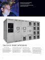
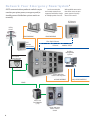
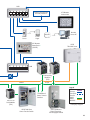
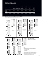
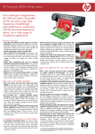
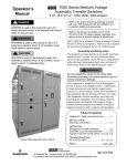
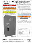
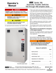
DISCOVER THE AWESOME POWER
OF THE ASCO LOW VOLTAGE
7000 SERIES GENERATOR PARALLELING
CONTROL SWITCHGEAR
You’re in Total Command
The ASCO 7000
SERIES Generator Paralleling
Control Switchgear is the
world’s most intelligent and
advanced multiple-engine
power control system.
1
It can be custom engineered
to meet the specific requirements of any project in a
wide range of emergency
power applications... from
industrial/commercial to
large healthcare and
business-critical facilities.
The 7000 SERIES system is
based on state-of-the-art
digital control technology
to synchronize, manage and
parallel engine-generator
sets. It provides sophisticated engine control, load management and communications capabilities, including
unsurpassed power system
monitoring and protection.
OPERATIONAL MODES :
PRIME POWER
EMERGENCY/AUTOMATIC STANDBY POWER
UTILITY PARALLELING
System Highlights
7000 SERIES Generator Paralleling Control Switchgear
For Mission-Critical and Healthcare Applications
Standard Integrated Features :
•
•
•
•
•
•
115-600V, 3-phase, 4-wire, 100%
neutral, 25% copper ground bus,
50/60 Hz, AC system
UL 1558 construction, listing
and labeling
Master control: 12” color touch
screen operator interface panel
Generator PLC redundancy
Two manual paralleling provisions
Load control for up to 128 power
transfer switches/circuit breakers
•
•
•
•
Load demand and bus load
optimization controls
No traditional (external) load share
components are required
Serial modbus RTU ( Master/slave
RS485/RS232 ports or Ethernet
communication capability with
power transfer switches and
SCADA system)
Event log and historical date
trending
Custom Configuration Design Options :
•
•
•
•
•
•
•
•
•
Up to 10,000A silver plated main
bus with up to 200kAIC bracing level
for four cycles
Generator breaker frame
size – up to 5,000A
Enclosure types: NEMA 1;
NEMA 3R
Bus duct risers up to 6,000A
Top or bottom conduit entry
Unlimited number of engine generators for parallel operation
Color touch screen panels for the
generator controls
Master PLC redundancy:
Hot standby or hot standby
synchronized
42-in. LCD graphic display
panel – integrated into the switch-
•
•
•
•
•
•
•
gear line-up and/or stand alone
- wall mounted
Two types of the remote
annunciation panels available
(LED or touch screen type)
Up to two remote annunciation
panels for each system, located up
to 6,560 feet from switchgear
Any specified circuit breaker brand
Electrically and/or manually operated distribution circuit breakers
Communication with building management network for monitoring
via Data Concentrator or firewall
Internet/intranet connectivity via
ASCO Thin Web Server
Extended switchgear warranty – up
to 5 years
2
42”
Fig. 1
A Smart
24 x 7 x 365
Power Guard
The 7000 SERIES Generator Paralleling
Switchgear Stands Ready 24 x 7 x 365,
Ensuring Immediate and Reliable
Response to a Loss of Utility Power.
3
When normal source
power fails… the switchgear power control system
(PCS) will start all enginegenerators when the power
transfer switches sense a
power outage. The first
generator to achieve an acceptable level of voltage and
frequency connects to the
emergency bus. A PCS
signal initiates connection of
the priority one loads to the
emergency bus. The switchgear then synchronizes
the remaining generator(s),
connects each to the bus…
and signals all power transfer
switches to connect
priority loads to the emergency source in a userdefined priority sequence.
If a generator fails…
the system automatically
disconnects it from the emergency bus, shuts it down and
signals the associated lowest
priority loads to shed.
Typical Applications:
The elevation (Fig. 1) and
one-line diagram (Fig. 2)
show a typical, four enginegenerator paralleling system
for automatic standby operational mode.
(Figs. 3-4) show typical
systems with four enginegenerators for utility
paralleling operational mode.
Fig. 2
TO UTILITY
FEED
Fig. 3
Load Demand … is
a load management feature that automatically
determines and keeps the
minimum required number
of generators online to
carry the actual kW load,
conserving fuel and reducing engine run time.
Bus Load
Optimization…
automatically sheds blocks
of load to prevent overloading of the remaining
generators, and automatically re-adds individual loads
to the bus per a prescribed
sequence according to their
priority value if any generator fails.
Parallel with Utility…
can be added to the standby
and prime power PCS
automatic closed-transition
operational mode that helps
Fig. 4
reduce energy costs by
shaving your facility’s peak
energy demand and/or export/import power to/from
the electric utility.
When Normal Source
Power Is Restored…
ferred to the normal position, the PCS will simultaneously open the generator
breakers and allow running
to their programmed
cooldown period… PCS is
now back to Automatic
Standby/ (or Utility) Mode.
each ATS senses a utility
source that is within tolerance and, after a time delay,
individually re-transfers to
the normal position. When
the last ATS has re-trans-
4
ASCO is the global leader in
power switching and controls
Creative, responsive, customer - focused
and competitive.
ASCO’s state-of-the art
large power laboratory
allows new equipment prototype and performance
testing under real conditions. This helps qualify
designs under listing agency
standards.
Dependable Project
Management
Our Innovative Design
and Development
Engineering Team
is a carefully selected
combination of experienced
engineers with decades
of accomplishments and
advanced degrees, and the
most recent college graduates in power engineering.
As one team, they successfully apply cutting-edge
technology to research,
develop and quickly implement new paralleling switchgear/power switching and
controls solutions.
5
is provided by more than
20 regional project
managers.
Each project manager is
accountable for the total
satisfaction of customers–electrical contractors,
owners, construction managers, consulting engineers,
engine-generator dealers,
channel partners and others.
He ensures that all of his
projects are completed
accurately, ontime and
meet the quality standards
expected by his customers
at each stage–submittals,
approvals, all drawings,
changes, deliveries, interfaces, start-ups, etc.
Our Professional
Product Management
teams are a vital bridge
between engineering and
sales. That’s why every
ASCO Power Switching and
Controls product line has a
dedicated manager.
ASCO Product Managers
have experience in power
switching and control design
and applications engineering. They also know how to
develop products that respond to evolving customer
needs so they can effectively
drive our design teams to
create the next-generation
of PCS switchgear technology, ensuring our continued
market leadership.
Knowledgeable
Applications
Engineering and Sales
Forces are large enough to
cover all regions nationwide
and internationally.
Applications engineers
are well-trained, highlyskilled and ready to sat-
isfy your particular power
control requirements.
Every member of the
applications engineering
team provides technical
support and quotations for
any power switching and
controls product regardless
of voltage class, product
type or application.
Best-in-the-Industry
Field Service is provided
by more than 100 skilled
technicians who properly
maintain and test power
control systems and
transfer switches coast to
coast.
Emergency service is
dispatched and technicians
are available 24/7 in most
areas. Fully stocked ASCO
vans support them during
on-site visits, including
switchgear startups.
Maximum reliability and excellent value
PCS Switchgear Design
Supports Reliable Operation
Dedicated Master Controls
send engine start signals to
generators and provide load
management within entire
emergency power system.
In the event the Master PLC
fails, the master controls will
still issue engine start signals allowing all loads to be
energized by closing breakers manually or by initiating
ATS’s transfer automatically
Master PLC Redundancy
is available for hot
standby or hot standby
synchronized
Two Manual Paralleling
Provisions are a touch
screen with a synchroscope
and additional push-buttons
mounted on the Master
Section door
Best Battery System
circuitry selects the best DC
source among the generator
starting batteries to provide
regulated control power to
the Master and all Generator controls, including
PLC’s (even during engine
cranking). Also, any engine
battery can feed the paralleling circuit breaker shunt
trip if that engine battery
has failed
Priority Load Control automatically adds load to the
generator bus as generators
come online, and shed load
as kW load capacity decreases. Loads are added in
an optional stepping fashion
to minimize transients on
the engine generator and
the system bus
Manual Load Shed Bypass
allows operator to manually re-add previously shed
load via push-buttons. In
the event of operator error,
the controls will protect the
power system – subsequent
overload will automatically
re-shed load detected by
bus under frequency
Bus Load Optimization
allows automatic shed
block(s) of load shedding
when any generator online
fails to prevent overloading
of remaining generators and
re-add loads to the system
bus according to their priority value and a prescribed
user selectable sequence
Generator Controls can
be designed within dedicated individual generator
sections or dual generator
sections. In both approaches, the controls enable
generator PLC redundancy
– if one generator PLC fails
the second generator PLC
takes over. The generator
PLC provides engine start/
stop, cranks the engine,
monitors engine alarms and
shutdowns and controls the
paralleling breaker
Multiple (Master OIP type)
Touch Screens are available
for the generator controls
Firewalled Communication facilitates communication with building management monitoring networks
via Ethernet data and/or
Concentrated (Gateway
PLC) Modbus
6
The heart of ASCO’s Power Control System is
a fully integrated Digital Paralleling Controller
with cutting-edge technology
ASCO Digital Paralleling
Controller (DPC)
Front
Rear
The controller uses a real-time operating system and offers the following advantages:
•
•
•
Hot-backup programmable logic controller
(PLC) capability.
True RMS sensing
for power metering
with the two, 3-phase
600VAC and two, 3phase 0-5A inputs.
Customized programming including screens
using ladder logic
from a single software
package.
•
•
•
Complete generator control logic with
ATS intelligent power
transfer, soft loading
and unloading, base
load and import/export
operations.
Manual paralleling with
graphical synchroscope.
Graphical 270-degree
gauge-type meters for
power instrumentation.
Compare two generators together and
generator with a total
bus on one screen.
•
•
•
•
•
Electrical one-line
diagram representation
showing circuit breaker
positions on generators,
feeders and ties.
Programmable 3-phase
•
generator and utility
relay protection functions.
Data trending up to
•
16 parameters, with
auto/manual triggering of data storage on
compact flash.
Compact flash slot
and card for capturing
screen displays and data
for remote analysis.
Remote monitoring via
building management
network (Modbus RTU
Serial RS485 and/or
Modbus TCP/IP Ethernet).
Remote diagnostics
using industrial-grade
analog modem or
Ethernet IP connection.
Peer-to-Peer networking between units,
supporting CAN,
DeviceNet, Modbus or
Ethernet protocols.
7
12:12 PM
Logged In-2
ASCO
Metering
Generator 1
Digital Paralleling Controller
Generator Bus Total
300
BUS
200
300
60
400
ASCO
58
200
62
ASCO
60
400
ASCO
58
BUS
62
ASCO
GEN 1
GEN 1
VOLTS
100
500
Dual Metering
480V
Manual Paralleling
250
Gen Protection
450
750
ASCO
300
AMPERES
0
Multi - Trending
150
1000
ATS Status
KILOWATTS
Event Log
VOLT AMPERES
200 x1000 1000
Main Menu. Easily navigate through all screen displays
from the Main Menu. Log in here to gain access to various levels of information.
ATS Status
1200
800
400
KILOVARS
-600
600
O
W
A
B
C
481
481
452
450
450
kWH
0
ASCO 1600
ASCO
SY
N CH
ROSCO
-800
VOLT AMPERES
400 x1000 2000
PE
VOLTS
AMPS
100
400
ASCO
PF
800
KILOVARS
-1200
750kVA
480
0.80
600kW
.
FA
S
1500
-400
T
AMPS
PF
1 of 2
904A
GEN 4
1200
ASCO
KILOWATTS
300
2000
225kVAR
VOLTS
Log In
AMPERES
0
200
-400
.
Alarm Status
750
ASCO
375kVA
12:12 PM
Logged In-2
GEN 2
900
600
1500
ASCO
0
-200
800
ASCO
500
300kW
600
400
One - Line
64
60.00Hz
1000
600
ASCO
452A
kW Trending
HERTZ
56
GEN 3
500
Gen Setup
500
480V
GEN 3
GEN 4
System Setup
VOLTS
100
64
60.00Hz
SL
Single Metering
HERTZ
56
GEN 2
1200
450kVAR
A
B
C
480
481
481
904
900
900
0.80
kWH
200
Dual Metering. Simultaneously view metering for any
two generators. When viewing bus metering on the
right side, a synchroscope will show if the source on the
left side is in phase with the bus.
12:12 PM
Logged In-2
NEXT
Manual Paralleling
Generator 1
Norm. Emer.
Source Avail.
ATS Position
kW
Bypass Pos.
Byp.
50
Act.
Load Shed
Norm. Emer.
Priority
101
Engine Start
ATS-2
Source Avail.
ATS Position
Bypass Pos.
Byp.
Act.
Load Shed
Off
Auto
0.0
Engine Start
ATS-4
Norm. Emer.
Source Avail.
Byp.
Act.
Load Shed
50
Auto
Off
Auto
0.0
Bypass Pos.
50
0.0
Engine Start
ATS-5
Norm. Emer.
Source Avail.
ATS Position
Act.
Load Shed
Hand
Off
Bypass Pos.
Bypass Pos.
50
Auto
Norm. Emer.
kW
Act.
Off
Auto
0.0
103
GEN 2
1 of 2
50
K
V
A
R
S
1
0
0
0
1
0
0
0
0
0
29.68
Time (sec)
6
5
0
0
F
r
e
q
u
e
n
c
y
Voltage L - N
3
0
0
V
o
l
t
s
1
0
0
0
0.0
29.76
Time (sec)
STOP
Gen 1 - Red
Freq Setpt
Manual Control
RAISE
RAISE
RAISE
RAISE
LOWER
LOWER
LOWER
LOWER
Load
Act.
Off
Auto
PF
FREQ
kW
480
0.8
GEN
60
300
BUS
480
0.8
BUS
60
600
Sync Mode
OFF
50
Time Dly.
Hand
VOLTS
GEN
Priority
0.0
Gen Status
CB Status
FA
S
W
O
ASCO
RUN
Not in Auto
CB Control
CHECK
SY
N CH
Auto Start
PERM
Running
PE
ROSCO
OPEN
EMERGENCY
STOP
CLOSE
OFF
0.0o
Manual Paralleling. Manually adjust the voltage and
frequency of the on-coming generator and manually
initiate the closing of the paralleling breaker.
12:12 PM
Logged In-2
NEXT
Generator One-Line
29.68
Time (sec)
Frequency
Generator 1
5
5
0
0
0
0.00
KW Setpt Frequency
PF
kVars
1
0
0
0
K
W
A
T
T
S
GEN 4
kW
Byp.
Load Shed
Multi Trending
kW Trending
1
0
0
0
0
Voltage
GEN 3
ATS Status. If the ATS’s are provided with communications capability, this advanced ATS Status screen provides additional information, such as source availability
and ATS position.
12:12 PM
Logged In-2
PF Setpt
106
ATS Position
Time Dly.
Hand
Volt Setpt
Engine Start
ATS-6
Priority
105
Byp.
GEN 1
Manual Control
Time Dly.
ATS Position
Load Shed
Priority
kW
Byp.
Source Avail.
Time Dly.
Hand
kW
0.00
T
kW
Bypass Pos.
Off
Hand
Priority
104
ATS Position
Source Avail.
Time Dly.
Time Dly.
Hand
Norm. Emer.
Priority
102
0
Engine Start
ATS-3
SL
Engine Start
ATS-1
0
Gen 3 - Blue
Gen 2 - Yellow Gen 4 - Green
29.76
Time (sec)
AUTO SCREEN
CAPTURE
OFF
Multi-Trending. Trend up to four parameters per screen
at the same time with the option to automatically perform a screen capture to a compact flash card every five
minutes.
Generator 2
Generator 3
Generator 4
Not in Auto
Not in Auto
Not in Auto
Not in Auto
Auto Start
Auto Start
Auto Start
Auto Start
Running
Running
Running
Running
VOLTS
480
VOLTS
480
VOLTS
480
VOLTS
0
AMPS
452
AMPS
452
AMPS
0
AMPS
0
FREQ
60
FREQ
60
FREQ
0
FREQ
0
kW
300
kW
300
kW
0
kW
kVARS
225
kVARS
225
kVARS
0
kVARS
0
PF
0.80
PF
0.80
PF
0.00
PF
0.00
0
One Line. See up to four generators on a single screen
with power flow indication, metering, and status information.
8
N e t w o r k Y o u r E m e r g e n c y Power System*
ASCO communications products make it easy to
monitor your prime power, emergency and/or
standby power distribution systems onsite or
remotely.
Local area networks
and remote networks are
supported with either single
or multiple points of access.
Web-enabled communications allow access to your
power system from anywhere in the world.
PCS Remote
Annunciator
Utility
Power
Engine-Generator
RS485 MODBUS
PCS
Remote
Annunciator
Engine-Generator
RS485 MODBUS
Fiber Optic Ethernet
Ethernet
Modbus TCP/IP
Building
Management
System
ASCO 5220
Power Manager
or RS485
ASCO 7000 SERIES
Power Control System
or RS485 MODBUS
RS485
ASCO 5110
Serial Module
(72A)
ASCO 7000 SERIES
Power Transfer
Switch
9
and/or RS485 MODBUS
HUB
Ethernet Connectivity
to Facility Network
ATS Remote
Annunciator
Internet
Remote
Access PC
E-mail
Pager
E-mail
Server
PCS Remote
PowerQuest ®
(SCADA)
ASCO
Thin Web Server
HUB
ASCO 5150
Connectivity
Modules
(72E)
Firewall
RS485
and/or
Legend
RS232
Ethernet
Fiber Optic
Ethernet
RS485
RS485
MODBUS
To Additional
Power Transfer
Switches
ASCO 5110
Serial Module
(72A)
* Exemplary diagram
ASCO 7000 SERIES
Power Transfer Switch
ASCO 7000 SERIES
Closed-Transition Transfer/Bypass Switch
10
World-class technology for
reliable power transfer
Typical Network Configurations
7000 SERIES Generator Paralleling Switchgear
can be interfaced with the downstream power
transfer switches by using the serial based,
Ethernet and/or hybrid (serial/Ethernet)
network communication methods as shown
in the diagrams below:
Serial (Acc. 72A on each ATS)
Switchgear Remote
Annunciation
7000 SERIES PCS Switchgear design offers
two types of Remote Annunciation Panels
in NEMA 1 enclosures. Both types of Remote
Annunciation Panels are capable of communicating with the paralleling SWGR via Ethernet.
LED type Remote
Annunciator has traditional
discrete LED status tiles to
provide system and individual generator’s remote
status, alarm (horn with
silencing push-button) and
display functions.
Ethernet (Acc. 72E on each ATS)
Ethernet Cables
(4) #14AWG
Hybrid - serial/Ethernet
(Acc. 72A on each ATS and Acc. 72E in
the Switchgear for each serial loop)
11
Touch screen type Remote
Annunciator with one 12-15
in. color display, which fully
duplicates the Master OIP
to provide system and individual generator’s remote
status, alarm (horn with
silencing push-button) and
display functions.
Dimensions
Distrib.
with 8002000AF
CB
Master/
Generator Utility Tie
Generator
Breaker
Controls
Controls (Single, Dual) Controls
Distrib.
with
3200AF
CB
Graphic
with 42”
LCD
At Main
Bus, A
Master
Controls
Up to
6,000A
32/72
32/72
32/72
32/72
26/72
32/72
32/72
700010,000A
32/84
32/84
32/84
32/84
26/84
32/84
32/84
MASTER/GENERATOR DIMENSIONS in(mm)
84”
(2134)
72”
(1829)
94”
(2388)
Master
84”
(2134)
72”
(1829)
Master/Gen
or Gen
94”
(2388)
32”
(813)
84”
(2134)
72”
(1829)
94”
(2388)
Dual Gen
32”
(813)
32”
(813)
DISTRIBUTION
DIMENSIONS in(mm)
72”
(1829)
84”
(2134)
84”
(2134)
72”
(1829)
94”
(2388)
26”
(660)
26”
(660)
32”
(914)
Notes:
1) Dimensions are for NEMA 1 type enclosures only
2) Section that includes 4000/5000AF Circuit Breaker(s)
will be 36 in. in width
3) A SWGR line-up consisting of a 5000AF CB will not be
UL 1558 listed
4) For NEMA 3R (outdoor) type enclosure each SWGR section
width will increase four inches.
5) Dimensions above are typical. They may vary depending
on custom specifications and design limitations
6) Dimensional data is approximate and subject to change.
Specified dimensions available upon request.
12
ASCO 7000 SERIES Generator Paralleling Co
System Operational
Modes
• Automatic standby
• Prime power
• Parallel with utility
System Control
• Load management
control (automatic
generator load demand
and bus load optimization) for up to 128 ATS’s
or electrically operated
feeder circuit breakers
• Manual load shed
bypass control with
bus under-frequency
protection
• Hard-wired engine start
and load shed relays
• System test without
load (off-line)
• Test with load (on-line)
• Emergency stop
• Audible alarm horn
• Automated manual
paralleling provisions
Engine Generator Control
• Automatic engine start
• Automatic synchronizing and paralleling
• Engine governor control, load sharing, soft
loading/unloading
• No external load
share components
required
• Adjustable engine
cool-down timer
System Controls
Redundancy
• Master PLC redundancy:
hot standby or hot
standby synchronized
• Multiple (Master OIP
type) touch screens for
the generator controls
• Real time clock
•
Two automated manual
paralleling provisions:
via touch screen with
a Synchroscope or via
push-buttons, mounted
on the master door
The Master Control Touch
Screen Operator Interface
Panel (OIP)
• ASCO DPC 12” or 15”
(optional) TFT color
• Real time clock
• Customized screens
with JCAHO records
capability
• Basic OIP Screens:
— Main menu
— System overview
screen with the
one-line diagram
— Metering (bus and
generators)
— Manual paralleling
control
— ATS status
— System setup
control
— Bus protection and
setup
— Engine generator
protection and
setup
— Utility control and
setup
— Utility metering
— Utility protection
and setup
— Utility status and
alarms
— Engine generator
alarms and shutdowns
— kW trending
— Multiple parameter
service trending
— Event data log
— Full range of service
— Log in
•
Compact flash card
portable memory
capability for storing
and capturing any of
displayed screens, including event data logs.
•
The Generator Control
Touch Screen
• ASCO DPC 12” or 15”
TFT color (optional)
• Screens to control and
monitor each or each
pair of generators
• Compact flash card
portable memory
capability for storing
and capturing any of
displayed screens, including event data logs.
•
Metering
• Voltage ( A-B, B-C,
C-A or A-N, B-N, C-N)
• Current A,B,C
• Frequency
• kW, kWh
• kVA
• kVar
• Power factor
• Synchroscope
• Engine battery voltage
• Running time meter
System Bus Protective
Relaying
• 0.25% accuracy
• Based on true RMS
sensing
• Device 27/59 - bus under/over voltage relay
(three phase)
• Device 81O/U – bus
over/under frequency
relay
Generator Protective
Relaying
• 0.25% accuracy
• Based on true RMS
sensing
• Device 27/59 under/over voltage
relay (three phase)
•
•
Device 81O/U – over/
under frequency relay
Device 32 – reverse
power relay
Device 40Q –loss of
excitation (reverse VAR)
relay
Device 15/25V – auto
and manual synchronizing relays
Engine Protection Alarms
(if properly equipped)
• Low coolant temperature pre-alarm
• High coolant temperature pre-alarm
• Low oil pressure prealarm and shutdown
• Low fuel alarm
• Low engine battery
alarm
• Over-crank shutdown
• Over-speed shutdown
Utility Protective
Relaying (for parallel with
utility mode with utility-tie
controls only)
• 0.25% accuracy
• Based on true RMS
sensing
• Utility grade type,
discrete or multi-functional solid state, field
adjustable relays
• Device 32 – reverse
power relay (three
phase)
• Device 27/59 under/over voltage
relay (three phase)
• Device 81O/U – over/
under frequency relay
• Device 47 –negative
sequence voltage relay
• Device 67 - directional
overcurrent relay
• Device 86 – lockout
relay
13
ntrol Switchgear Specifications*
PCS Power Supply
• Best DC source selector
system
• Power from 24VDC
engine start batteries
• DC-DC converter
System Communications
• Serial modbus RTU master/slave (RS 485/232
ports)
• Ethernet 100-base-T
supporting modbus
TCP/IP
• CAN network peer-topeer protocol
• DeviceNet master/slave
Remote Power Monitoring
Options
• Standard or customized
PC based SCADA (ASCO
PowerQuest ®) remote
power monitoring system via Ethernet
• 42 in. LCD mimic
graphic panel (mounted
in the switchgear lineup or stand alone) to
display the emergency
power system elements,
including ATS’s.
• Firewalled communication capability with
building management
system network via Ethernet or data concentrated (Gateway PLC)
modbus slave
• Remote Internet/intranet connectivity
via internal or external
ASCO Thin Web Server
Remote Generator Alarm
& Status Annunciation
• Up to two optional
Remote Annunciator
panels, touch screen
type or LED lamp
type, with monitoring
capability to provide
the total system and
individual generators’
status, alarms and
display functions
• Capability to locate
Remote Annunciation
panels up to 6500 feet
(2000 m) from the
paralleling switchgear
via fiber optic Ethernet
communication
• Compliance with
NFPA 99
Additional Optional
Features
• Breaker lifting devices
(portable or overhead)
• Load bank circuit
breaker
• Electrically or manually
operated distribution
breakers
• Spare parts
• Circuit breaker test kit
• Custom sized 24VDC
station battery system
(including batteries,
rack and charger).
• Extended (up 5 years)
ASCO Warranty.
Circuit Breakers
• UL 1066 ( ANSI C37)
rated, drawout, power
circuit breakers (any
specified brand) with
frame size up to 5000A.
• Up to 200 kAIC rated
(including fused breakers)
• Electrically operated
on generators and
distribution
•
•
•
•
5 cycle closing
Auxiliary and bell alarm
contacts
Electronic trip units
with LSIA functions on
generators and LSIG
or LSI trip functions on
distribution
Power metering
and communication
capability
Enclosure and Bus
• UL 1558 constructed,
listed & labeled
• Up to 600V, 3-phase,
4-wire AC system, 100%
copper neutral and 25%
ground bus
• Up to 10,000A
main bus
• Silver plated copper
bus with up to 200kAIC
bracing level for 4 cycles
• Bus duct risers available
– up to 6000A
• Top and bottom conduit
cable entry
• Mechanical set screw
type or compression
type lugs
• Enclosure types:
NEMA 1, NEMA 3R,
(consult ASCO for
design limitations)
• Pull Boxes for NEMA 1
type enclosure
• ANSI gray
• Shipping splits at
each section to ease
installation
Environment
• Temperature range
0oF to 125oF (-18 0oC
to 52oC)
• Humidity range 0 to
95%, non-condensing
* For detailed specifications please
request publication 3179
14
A SCO Power Te chnologies
50 Hanover Road
Florham Park, NJ 07932
USA
8 0 0 8 0 0 A SCO
www.ascopower.com
www.ascoapu. co m
Emerson Network Power.
The global leader in enabling Business-Critical ContinuityTM.
EmersonNetworkPower.com
Outside Plant
AC Power
Connectivity
Embedded Computing
Embedded Power
DC Power
Infrastructure Management & Monitoring
Power Switching & Controls
Precision Cooling
Racks & Integrated Cabinets
Services
Surge Protection
Emerson Network Power and the Emerson Network Power logo are trademarks and service marks of Emerson Electric Co. ©2009 Emerson Electric Co.
Publication 3181 R2
© June, 2009
Printed in the U.S.A.