1
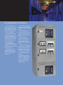
For commercial, Healthcare,
dataCenters and industrial
facilities...wherever control
of on site generators is needed
The ASCO Series 346 Digital Power
Control System is a standardized
generator paralleling system
offering the sophisticated
functionality normally found in
custom designs.
• Reliably starts, synchronizes, parallels, monitors and protects engine generator sets for prime power and
emergency power applications.
• Smoothly integrates engine-generator
sets and power transfer switches.
• Automatic load management control. One priority block per generator, each
handling up to eight loads per priority
block, up to four generators.
• Provides full, self-contained
configurability. No need for a laptop.
• Includes communication ports that
provide internet and intranet access to
system status and functions.
• Easy to install, set up, commission,
operate and service.
1
Series 346 Digital Power Control System
The ASCO Series 346
Power Control System offers wide-ranging features that
make your facility’s emergency power system more
effective and efficient.
Digital microprocessorbased technology streamlines and simplifies total
generator load control and
engine management. The
entire control system fits
into one enclosure.
The technology is
compatible with engines
equipped with an electronic
engine speed controller and
voltage regulator.
A significantly smaller
footprint meets the demanding requirements of
tight or unconventional
floor spaces.
Quicker manufacturing
lead times and standardized
configuration produce faster
delivery.
Door-mounted, software-based display screens
communicate easy-to-understand information in less
space.
Digital metering measures voltage, amps,
watts and frequency. It
also includes protective
relay functions as standard
features.
Drawout insulated-case
circuit breakers that parallel
the generator to the emergency bus are an integral
part of the system’s design.
The system is rated at
800 to 3,000 amperes per
generator.
It, of course, meets or
exceeds the requirements of UL 891 and applicable
standards of NEMA, IEEE,
and ANSI. The system is
labeled UL 891.
2
World-class technology for
reliable power transfer
Independent
g e n e r ato r co n t ro l
Independent Digital Generator Control Panels
manage emergency standby systems comprised of up to four engine-generators
Independent microprocessor-based Digital Generator Control Panels provide
complete generator load
control and engine management for generators ranging in capacity from 250 kW
to 2 MW.
Each control panel monitors an engine-generator, displays parameters
for that engine-generator,
annunciates generator and
engine alarms, and controls
engine speed and generator voltage for synchronizing and isochronous load sharing.
3
The panels automatically
synchronize voltage and
frequency, and match phase
angles within two degrees
of phase and 0.1 percent
of voltage. Real (kW) load
control and reactive (kVAR)
controls are also included.
Each control panel also
operates its respective
generator circuit breaker,
integral to the system, for
paralleling or shutdown.
Safe dead bus closing
ensures that only one gen- erator connects to the bus
at a time.
Using integrated control
logic, the system transfers
the highest priority block of
load to the first engine-generator that produces acceptable voltage and frequency.
Operator interface
screens display:
• System status
• Engine status
• Generator metering
• DGCP input/output
• Synchronization status
• Load status
• PF/kVAR status
• Alarm/ Event log
The control panels have
five levels of built – in
security to protect against
configuration changes and
alarm purges by unauthorized personnel. A laptop is
not required to configure
the system.
A Modbus® RTU RS422
port enables communication to remote systems and
allows those systems to access engine and generator
parameters.
Communication Products
The optional ASCO
5500 Thin Web Server
provides Web-enabled
control.
An operator or
supervisor can monitor
various transfer switch,
engine and generator
parameters remotely using
the Thin Web Server.
The server provides
real time access and control
of critical power system
performance.
Generator Breakers
Generator circuit
breakers offer drawout
convenience to simplify
maintenance or
replacement.
Users can manage,
check system status and
recognize potential system
failure.
It requires no dedicated
hardware or software
to operate and can be
connected to any standard
PC with a Microsoft®
Internet Explorer browser.
E-mail and text paging
features alert users of
abnormal conditions.
Electrically-operated
front-serviceable drawout
breakers are available in
800 amp to 3000 amp
frame sizes.The Square D,
NW, 5.0P insulated case
circuit breakers are UL 489
listed and are included with
an adjustable long time
delay, short time delay,
instantaneous overcurrent
trip and ground fault alarm.
Additional features
include 120VAC electrical
operation, 24 VDC shunt
ASCO 5500 Thin Web Server.
The optional ASCO 5150
Connectivity Module provides Ethernet and RS485
Communications to Asco
Transfer Switch controllers
and Asco Power Managers.
Embedded HTML pages
are provided for monitoring
of electrical parameters and
alarms. The communication
format will support up to 8
clients simultaniously over
an Ethernet Connection.
An ASCO 5110 communication module also available
with only RS485 communications for monitoring and
control with ASCO PowerQuest® systems.
ASCO 5350 Remote Annunciator.
trip, bell alarm, 4a and
4b auxiliary contacts, a
protective cover for the
manual close pushbutton,
and instantaneous and
ground fault indications.
Square D Micrologic
5.0P Trip units provide
monitoring of electrical
parameters as well as visual
indication. Trip settings
are adjustable from 40 %
to 100% of the generator
breaker frame size and
a Modbus® RTU port
provides communications
to the Emergency Power
Communication System.
Generator Protection
• Device 27/59- Under
•
•
•
•
•
and Over Voltage
Device 81- Under and Over Frequency
Device 32- Reverse Power (Inverse Time Delay)
Device 40- Loss of
Excitation
Device 81U- Bus Under Frequency
Over Current (Inverse Time Delay)
Synchronizing
• Phase Match
Synchronization
• 3 Mode Operation: Run,
Check, Permissive
• Voltage Matching
• Dead Bus Closing
• Synch Timer
• Reclose Attempt/Timer
• Manual Synchronization
(Permissive Mode)
Generator Voltage
And Reactive Load
Control
•
Generator breaker and bus ampacity1,3
GEN SIZE
(kw @480V)
230 - 500
300 - 650
350 - 800
450 -1000
550 -1250
700 -1500
800 -2000
indicate switch status
and position, while
separate push buttons
individually initiate transfer
switch operation and
testing. Transfer switch
annunciators can be set
up in multiple locations to
monitor various transfer
switches, allowing
redundant and distributed
annunciation.
Breaker Frame
(Amps)
Breaker Trip
(Amps)2
800
1200
1200
1600
2000
2500
3000
800
1000
1200
1600
2000
2500
3000
1. Square D MASTERPACT® NW Insulated Case Circuit Breaker
2. Adjustable Trip Settings 40% to 100% of Breaker Frame Size
3. Bus bracing level 100,000 amperes.
8
Sy s t e m F u n c t i o n s
• Power Factor Sharing In
ASCO 5150 Connectivity Module.
The ASCO 5350 Power
Transfer Switch Remote
Annunciator is a standalone, industrial grade
interface device providing
you with the most critical
transfer switch status
indication and transfer/
retransfer control for up to
eight switches. Ethernet
technology is built in for
faster and more reliable
communications. LEDs
Maximum Reliability & Excellent Value
9
Phase &Neutral
Bus (Amps)
2500
2500
2500
4000
4000
6000
6000
Ground Bus
(Amps)
1000
1000
1000
1000
1000
2000
2000
•
Load Sharing Mode
Externally Adjustable Var/Pf Reference
Manual Voltage Control
AC Metering
• 3 Phase Voltage
• 3 Phase Current
• kWh
• kW, kVA, and kVAR
• Power Factor
• Frequency
Engine Control
• Multiple Crank Cycle Timer
• Crank Timer
• Crank Fail Alarm/ Shutdown
• Crank Cutout (Rpm)
• Engine Preglow
• Idle/Rated Relay Output
• Engine Runtime
Engine Protection
• Oil Pressure -Over/ Under Alarm/Shutdown Settings
• Water Temperature - Over/Under Alarm/
Shutdown Settings
• Battery Voltage - Over/ Under Alarm/Shutdown
Settings
• Overspeed - Alarm/
Shutdown Settings
4
Priority load management
One priority block per generator with eight loads
per block, such as electrically operated load
distribution circuit breakers or power transfer
switches, can be block load controlled.
A Generator Control Station includes a five-position selector
switch for each engine generator. The settings are lockout/reset,
off/cooldown, automatic test off line and test on line. Indicator
lights signal when the generator is running and when controls are
not in the automatic operation.
An under frequency
monitor on the main bus
monitors generator loading.
Lowest priority loads
will be shed automatically
so critical priority one
loads stay energized if
the generators become
overloaded, if one of the
running generators fails,
or if one of the generators
fails to start when a power
outage occurs.
Visual indication
identifies the status of
priority load blocks and a
push-button allows for a
manual override of shed
load blocks.
Network Your Emergency
Power System
ATS Remote
Annunciator
Utility
Power
Twisted Pair
Gen Communications
5
Ethernet
Building
Management
System
ASCO - Thin
Web Server
with Embedded
HTML Pages for
Monitoring and
Control
ASCO 5220D
Power
Manager
Internet
HUB
Remote
Access
PC
(Accessory LD)
A System Control Station includes an alarm horn with alarm silence
push-button. Push-buttons are also included for resetting priority
two loads and the under frequency alarm. Visual indication
provides status of priority two, three or four loads and emergency
mode operation.
Maintenance
Room PC or
Facility
Network
RS232
Engine Generator
Engine Generator
ASCO 5150
Connectivity
Module
RS485 MODBUS
If an under-frequency
bus condition is detected,
the system will exit load
demand mode and signal
all additional engines to
start and come online. If an
engine fails while in load
demand mode, all additional
generators will be signaled
to start and come online,
and the lowest priority loads
will be shed.
HUB
Engine Generator
Communications Module
ASCO Series 346
Generator
Paralleling
System
(up to four engines)
Load demand management
Available on Two Engine Systems
In the optional load
demand mode with more
than one generator online,
the system monitors total
load demand. If the load
falls below 80% of rated
output of the highest
priority generators, lower
priority engines (selectable)
will shut down after an
adjustable time delay. If the
load increases above 90% of
rated output of the highest
priority generators already
operating, the next priority
engine will be signaled to
start and come online after
an adjustable time delay.
ASCO communications products allow for the monitoring and control of your emergency or
standby power distribution system. Local area networks and remote networks are supported with either
single or multiple points of access, and web-enabled communications allow access to your power system
from anywhere in the world.
Email
Server
RS422 MODBUS
RS485
RS485
To Additional
Automatic Transfer
Switches
Legend
ASCO 5110
Communication
Module
ASCO 5110
Communication
Module
ASCO Series 300
Automatic Transfer
Switch
ASCO 5110
Communication
Module
ASCO 4000 Series
Automatic Transfer
Switch
ASCO 7000 Series
Bypass Isolation
Transfer Switch
6
RS232
Ethernet
RS485
RS485
MODBUS
RS422
MODBUS
Email
Pager
ASCO 7000 Series
Closed Transition-Bypass
Isolation Transfer Switch
7
Communication Products
The optional ASCO
5500 Thin Web Server
provides Web-enabled
control.
An operator or
supervisor can monitor
various transfer switch,
engine and generator
parameters remotely using
the Thin Web Server.
The server provides
real time access and control
of critical power system
performance.
Generator Breakers
Generator circuit
breakers offer drawout
convenience to simplify
maintenance or
replacement.
Users can manage,
check system status and
recognize potential system
failure.
It requires no dedicated
hardware or software
to operate and can be
connected to any standard
PC with a Microsoft®
Internet Explorer browser.
E-mail and text paging
features alert users of
abnormal conditions.
Electrically-operated
front-serviceable drawout
breakers are available in
800 amp to 3000 amp
frame sizes.The Square D,
NW, 5.0P insulated case
circuit breakers are UL 489
listed and are included with
an adjustable long time
delay, short time delay,
instantaneous overcurrent
trip and ground fault alarm.
Additional features
include 120VAC electrical
operation, 24 VDC shunt
ASCO 5500 Thin Web Server.
The optional ASCO 5150
Connectivity Module provides Ethernet and RS485
Communications to Asco
Transfer Switch controllers
and Asco Power Managers.
Embedded HTML pages
are provided for monitoring
of electrical parameters and
alarms. The communication
format will support up to 8
clients simultaniously over
an Ethernet Connection.
An ASCO 5110 communication module also available
with only RS485 communications for monitoring and
control with ASCO PowerQuest® systems.
ASCO 5350 Remote Annunciator.
trip, bell alarm, 4a and
4b auxiliary contacts, a
protective cover for the
manual close pushbutton,
and instantaneous and
ground fault indications.
Square D Micrologic
5.0P Trip units provide
monitoring of electrical
parameters as well as visual
indication. Trip settings
are adjustable from 40 %
to 100% of the generator
breaker frame size and
a Modbus® RTU port
provides communications
to the Emergency Power
Communication System.
Generator Protection
• Device 27/59- Under
•
•
•
•
•
and Over Voltage
Device 81- Under and Over Frequency
Device 32- Reverse Power (Inverse Time Delay)
Device 40- Loss of
Excitation
Device 81U- Bus Under Frequency
Over Current (Inverse Time Delay)
Synchronizing
• Phase Match
Synchronization
• 3 Mode Operation: Run,
Check, Permissive
• Voltage Matching
• Dead Bus Closing
• Synch Timer
• Reclose Attempt/Timer
• Manual Synchronization
(Permissive Mode)
Generator Voltage
And Reactive Load
Control
•
Generator breaker and bus ampacity1,3
GEN SIZE
(kw @480V)
230 - 500
300 - 650
350 - 800
450 -1000
550 -1250
700 -1500
800 -2000
indicate switch status
and position, while
separate push buttons
individually initiate transfer
switch operation and
testing. Transfer switch
annunciators can be set
up in multiple locations to
monitor various transfer
switches, allowing
redundant and distributed
annunciation.
Breaker Frame
(Amps)
Breaker Trip
(Amps)2
800
1200
1200
1600
2000
2500
3000
800
1000
1200
1600
2000
2500
3000
1. Square D MASTERPACT® NW Insulated Case Circuit Breaker
2. Adjustable Trip Settings 40% to 100% of Breaker Frame Size
3. Bus bracing level 100,000 amperes.
8
Sy s t e m F u n c t i o n s
• Power Factor Sharing In
ASCO 5150 Connectivity Module.
The ASCO 5350 Power
Transfer Switch Remote
Annunciator is a standalone, industrial grade
interface device providing
you with the most critical
transfer switch status
indication and transfer/
retransfer control for up to
eight switches. Ethernet
technology is built in for
faster and more reliable
communications. LEDs
Maximum Reliability & Excellent Value
9
Phase &Neutral
Bus (Amps)
2500
2500
2500
4000
4000
6000
6000
Ground Bus
(Amps)
1000
1000
1000
1000
1000
2000
2000
•
Load Sharing Mode
Externally Adjustable Var/Pf Reference
Manual Voltage Control
AC Metering
• 3 Phase Voltage
• 3 Phase Current
• kWh
• kW, kVA, and kVAR
• Power Factor
• Frequency
Engine Control
• Multiple Crank Cycle Timer
• Crank Timer
• Crank Fail Alarm/ Shutdown
• Crank Cutout (Rpm)
• Engine Preglow
• Idle/Rated Relay Output
• Engine Runtime
Engine Protection
• Oil Pressure -Over/ Under Alarm/Shutdown Settings
• Water Temperature - Over/Under Alarm/
Shutdown Settings
• Battery Voltage - Over/ Under Alarm/Shutdown
Settings
• Overspeed - Alarm/
Shutdown Settings
4
Ordering
i n fo r m at i o n
To order an ASCO 346 Series Generator Paralleling System, complete the following catalog number.
346
0800
M
N
6
Product
Amperes
Lug Type
Voltage Code1
Frequency Code
346
(2 Gens)
347
(4 Gens)
0800
1000
M
C
Mechanical
Compression
1200
1600
2000
2500
3000
A
B
C
D
E
F
H
J
K
L
M
N
P
Q
R
115
120
208
220
230
240
380
400
415
440
460
480
550
575
600
5
6
50 Hz
60 Hz
4
C1
Enclosure Depth2
4
6
7
8
Enclosure3
C1 NEMA Type 1
ANSI 61 Gray
F1 NEMA Type 3R
ANSI 61 Gray
C2 NEMA Type 1
ANSI 49 Gray
F2 NEMA Type 3R
ANSI 49 Gray
48”
60”
72”
84”
1. Consult the factory for systems other than 3 phase, 4 wire
2. Nema 1 systems 1200 amps and below are provided at 48” deep standard with an option to increase the depth to 60” or 72”. Nema 1 systems
1600 amps and above are provided 60” deep as standard with an option to increase the depth to 72”. Nema 3R systems 1200 amps and below are
provided 60” deep standard with an option to increase the depth to 72” or 84”. Nema 3R systems 1600 amps are provided 72” deep standard with an
option to increase the depth to 84”.
3. ANSI 61 Gray Standard.
The Example Catalog Number Above is 3460800MN64C
Sizes of UL-Listed Solderless Screw-Type Terminals for External Power Connections
Max # of
Max # of
Generator Breaker
Conductors per Conductors per
Rating amps
Gen Terminal Load Terminal
800
1000
1200
1600
2000
2500
3000
4
5
5
6
7
8
9
8
10
10
12
14
16
18
Range of CU
Range of AL
Max # of Ground
Bus Conductors Conductor Sizes Conductor Sizes
2
3
3
3
4
4
5
3/0 to 800 MCM
3/0 to 800 MCM
3/0 to 800 MCM
3/0 to 800 MCM
3/0 to 800 MCM
3/0 to 800 MCM
3/0 to 800 MCM
250 to 800 MCM
250 to 800 MCM
250 to 800 MCM
250 to 800 MCM
250 to 800 MCM
250 to 800 MCM
250 to 800 MCM
Pull Box Options3
Pull Box with out provisions for overhead lifting device1
Enclosure Depth in (mm)
48 (1219)
60 (1524)
72 (1829)
Accessory
Height in (mm)
Depth
Accessory
Height in (mm)
Depth in (mm)
42A1
42A2
42A3
12 (305)
12 (305)
12 (305)
48 (1219)
60 (1524)
72 (1829)
42A4
42A5
42A6
24 (610)
24 (610)
24 (610)
48 (1219)
60 (1524)
72 (1829)
Pull Box with provisions for overhead lifting device 1,2
Enclosure Depth in (mm)
48 (1219)
60 (1524)
72 (1829)
Accessory
Height in (mm)
Depth
Accessory
Height in (mm)
Depth in (mm)
42B1
42B2
42B3
12 (305)
12 (305)
12 (305)
24 (610)
36 (914)
48 (1219)
42B4
42B5
42B6
24 (610)
24 (610)
24 (610)
24 (610)
36 (914)
48 (1219)
1. All pull boxes are Nema 1, top mounted 36” wide.
2. An overhead circuit breaker lifting device with trolley, rails and mounting rails is available.Order as accessory 82.
3. Shipped separately, must be installed by contractor.
10
Dimensions and Shipping Weights
NEMA 1 (per section)**
800-1200 Amp
* Optional Enclosure Depths Code, 6 - 60 Inches
Code, 7 - 72 Inches
Shipping Weights**
Amps
800 - 1200
800 - 1200
800 - 1200
*
Depth
in(mm)
Enclosed
Weight lb(kg)
48 (1219)
60 (1524)
72 (1829)
1964 (892)
2024 (920)
2085 (948)
Dimensions and Shipping Weights
NEMA 1 (per section)**
1600-3000 Amp
* Optional Enclosure Depths Code, 7 - 72 Inches
Shipping Weights**
Amps
1600 - 2000
1600 - 2000
2500 - 3000
2500 - 3000
*
Enclosed
Depth
in(mm) Weight lb(kg)
60 (1524)
72 (1829)
60 (1524)
72 (1829)
2085 (947)
2206 (1003)
2385 (1084)
2506 (1139)
**Single section for two-generator systems; second section required for four generator systems
11
Dimensions and Shipping Weights
NEMA 3R (per section)**
800-1200 Amp
* Optional Enclosure Depths
Code, 7 - 72 Inches
Code, 8 - 84 Inches
Shipping Weights**
Amps
800 - 1200
800 - 1200 800 - 1200
Depth
in(mm)
60 (1524)
72 (1829)
84 (2134)
*
Enclosed
Weight lb(kg)
2274 (1034)
2334 (1061)
2395 (1089)
Dimensions and Shipping Weights
NEMA 3R (per section)**
1600-3000 Amp
* Optional Enclosure Depths Code, 8 - 84 Inches
Shipping Weights**
Amps
1600 - 2000
1600 - 2000
2500 - 3000
2500 - 3000
Depth
in(mm)
72 (1829)
84 (2134)
72 (1829)
84 (2134)
Enclosed
Weight lb(kg)
*
2395 (1089)
2516 (1144)
2695 (1225)
2739 (1245)
**Single section for two-generator systems; second section required for four generator systems
12
A SCO Power Te chnologies
50 Hanover Road
F l o r ham Park, NJ 07932
USA
8 0 0 8 0 0 A SCO
w w w. ascopower.com
w w w. ascoapu. co m
Emerson Network Power.
The global leader in enabling Business-Critical ContinuityTM.
EmersonNetworkPower.com
Outside Plant
AC Power
Connectivity
Embedded Computing
Embedded Power
DC Power
Infrastructure Management & Monitoring
Power Switching & Controls
Precision Cooling
Racks & Integrated Cabinets
Services
Surge Protection
Emerson Network Power and the Emerson Network Power logo are trademarks and service marks of Emerson Electric Co. ©2009 Emerson Electric Co.
Publication 3121 R4
© May, 2009
Printed in the U.S.A.