1
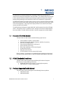
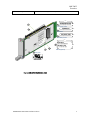
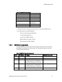
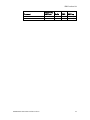
AMC-S402 Installation and Use 6806800H60A March 2009 © 2009 Emerson All rights reserved. Trademarks Emerson, Business-Critical Continuity, Emerson Network Power and the Emerson Network Power logo are trademarks and service marks of Emerson Electric Co. © 2009 Emerson Electric Co. All other product or service names are the property of their respective owners. Intel® is a trademark or registered trademark of Intel Corporation or its subsidiaries in the United States and other countries. Java™ and all other Java-based marks are trademarks or registered trademarks of Sun Microsystems, Inc. in the U.S. and other countries. Microsoft®, Windows® and Windows Me® are registered trademarks of Microsoft Corporation; and Windows XP™ is a trademark of Microsoft Corporation. PICMG®, CompactPCI®, ATCA™ and the PICMG, CompactPCI and ATCA logos are registered trademarks of the PCI Industrial Computer Manufacturers Group. UNIX® is a registered trademark of The Open Group in the United States and other countries. Notice While reasonable efforts have been made to assure the accuracy of this document, Emerson assumes no liability resulting from any omissions in this document, or from the use of the information obtained therein. Emerson reserves the right to revise this document and to make changes from time to time in the content hereof without obligation of Emerson to notify any person of such revision or changes. Electronic versions of this material may be read online, downloaded for personal use, or referenced in another document as a URL to an Emerson website. The text itself may not be published commercially in print or electronic form, edited, translated, or otherwise altered without the permission of Emerson, It is possible that this publication may contain reference to or information about Emerson products (machines and programs), programming, or services that are not available in your country. Such references or information must not be construed to mean that Emerson intends to announce such Emerson products, programming, or services in your country. Limited and Restricted Rights Legend If the documentation contained herein is supplied, directly or indirectly, to the U.S. Government, the following notice shall apply unless otherwise agreed to in writing by Emerson. Use, duplication, or disclosure by the Government is subject to restrictions as set forth in subparagraph (b)(3) of the Rights in Technical Data clause at DFARS 252.227-7013 (Nov. 1995) and of the Rights in Noncommercial Computer Software and Documentation clause at DFARS 252.227-7014 (Jun. 1995). Contact Address Emerson Network Power - Embedded Computing 2900 South Diablo Way, Suite 190 Tempe, AZ 85282 USA Contents PREFACE ....................................................................................................................................... IV SAFETY SUMMARY............................................................................................................................. IV FLAMMABILITY................................................................................................................................... V EMI CAUTION ................................................................................................................................... V SAFETY STATEMENT ............................................................................................................................ V CE NOTICE (EUROPEAN COMMUNITY) .................................................................................................... V ABOUT THIS MANUAL ................................................................................................................... VI HOW THIS MANUAL IS ORGANIZED ....................................................................................................... VI CONVENTIONS USED IN THIS MANUAL ................................................................................................... VI HARDWARE PREPARATION AND INSTALLATION............................................................................VIII UNPACKING INSTRUCTIONS ............................................................................................................... VIII ANTISTATIC PRECAUTIONS ................................................................................................................ VIII 1 AMC-S402 OVERVIEW........................................................................................................... 1 1.1 1.2 1.3 1.4 2 FEATURES OF THE AMC MODULE............................................................................................. 1 PICMG STANDARDS COMPLIANCE........................................................................................... 1 PRODUCTS SUPPORTED BY THIS MANUAL .................................................................................. 1 PART NUMBER, SERIAL NUMBER LABELS .................................................................................... 2 AMC-S402 INSTALLATION...................................................................................................... 4 2.1 INSTALLATION AND REMOVAL OF THE AMC-S402 MODULE .......................................................... 4 2.2 IMPORTANT INFORMATION ABOUT YOUR CHASSIS ....................................................................... 4 2.2.1 Safety Statement ............................................................................................................... 4 2.2.2 Observe Maximum Module Current Requirements .............................................................. 4 2.3 BEFORE YOU INSTALL OR REMOVE THE AMC .............................................................................. 4 2.3.1 Observe ESD Precautions.................................................................................................... 5 2.3.2 Watch for Bent Pins or Other Damage ................................................................................ 5 2.4 USE CAUTION WHEN INSTALLING OR REMOVING AMC ................................................................. 5 2.4.1 Preserve EMI Compliance.................................................................................................... 5 2.4.2 Understand Hot Swap ........................................................................................................ 6 2.5 VERIFY SLOT USAGE ............................................................................................................. 6 2.6 MODULE HOT-SWAP ............................................................................................................ 6 2.7 INSTALLING THE AMC MODULE............................................................................................... 7 2.8 REMOVING THE AMC MODULE ............................................................................................... 8 3 FUNCTIONAL DESCRIPTION ................................................................................................... 9 3.1 OVERVIEW ......................................................................................................................... 9 3.2 AMC-S402, TOP LEVEL BOARD LAYOUT .................................................................................. 9 3.3 SERIAL STORAGE I/O INTERFACES .......................................................................................... 10 3.3.1 SAS Port Isolation Multiplexor Circuit................................................................................ 10 3.4 POWER REGULATOR ........................................................................................................... 11 3.5 IPMI SUBSYSTEM ............................................................................................................... 11 4 CONNECTOR PIN ASSIGNMENTS .......................................................................................... 12 4.1 4.2 AMC-S402 PORT ASSIGNMENTS .......................................................................................... 12 AMC CONNECTOR, “FINGER” ASSIGNMENTS ........................................................................... 12 6806800H60A AMC-S402 Installation and Use i 5 SPECIFICATIONS .................................................................................................................. 15 5.1 PHYSICAL CHARACTERISTICS ................................................................................................. 15 5.1.1 AMC Module Height Exceptions ........................................................................................ 15 5.2 HARD DRIVE OPERATION AND STORAGE SPECIFICATIONS ............................................................ 16 5.3 POWER REQUIREMENTS ....................................................................................................... 17 5.4 EMC COMPLIANCE ............................................................................................................. 17 6 FRONT PANEL INDICATORS.................................................................................................. 19 7 IPMI FUNCTIONS LIST........................................................................................................... 20 7.1 IPMI AND MANAGEMENT CONTROLLER (IPMC)........................................................................ 20 7.2 SENSOR DATA RECORDS ...................................................................................................... 20 7.2.1 AMC Port Assignments ..................................................................................................... 21 7.3 SUPPORTED IPMI COMMANDS .............................................................................................. 22 8 IPMI FIRMWARE UPGRADE PROCEDURE ............................................................................... 24 8.1 THE IPMITOOL UTILITY ......................................................................................................... 24 6806800H60A AMC-S402 Installation and Use ii List of Figures Figure 1. AMC-S402 Module Top View, Front Panel........................................................................... 2 Figure 2. AMC-S402 Identification Labels .......................................................................................... 3 Figure 3. AMC Module Injector / Ejector Latch .................................................................................. 7 Figure 4. AMC-S402 Functional Blocks.............................................................................................. 9 Figure 5. AMC-S402 Top Level Board Layout ................................................................................... 10 Figure 6. AMC Front Panel Indicators .............................................................................................. 19 List of Tables Table 1 Conventions Used In This Manual..........................................................................................vi Table 2 AMC-S402 Identification Labels............................................................................................ 2 Table 3 Max AMC Module Current Requirements.............................................................................. 4 Table 4 I/O Ports Available On AMC Connector................................................................................ 10 Table 5 AMC-S402 Port Assignments.............................................................................................. 12 Table 6 AMC-S402 Module Edge, Pin Assignments ......................................................................... 13 Table 7 AMC-S402 Module Height Details, No Heat Sink................................................................. 15 Table 8 Environmental Specifications, Sas Disk Drives .................................................................... 16 Table 9 Power Requirements.......................................................................................................... 17 Table 10 EMC Emission Compliancy................................................................................................ 18 Table 11 LED Function.................................................................................................................... 19 Table 12 Sensor Data Records ........................................................................................................ 20 Table 13 Example FRU Data Records............................................................................................... 21 Table 14 AMC-S402 E-Key Port Assignments .................................................................................. 21 Table 15 Supported IPMI Commands ............................................................................................. 22 Table 16 Ipmitool Options Relevant to Firmware Upgrades ............................................................. 24 6806800H60A AMC-S402 Installation and Use iii Preface Safety Summary The following general safety precautions must be observed during all phases of operation, service, and repair of this equipment. Failure to comply with these precautions or with specific warnings elsewhere in this manual could result in personal injury or damage to the equipment. The safety precautions listed below represent warnings of certain dangers of which Emerson is aware. You, as the user of the product, should follow these warnings and all other safety precautions necessary for the safe operation of the equipment in your operating environment. GROUND THE INSTRUMENT. To minimize shock hazard, the equipment chassis and enclosure must be connected to an electrical ground. If the equipment is supplied with a three-conductor AC power cable, the power cable must be plugged into an approved three-contact electrical outlet, with the grounding wire (green/yellow) reliably connected to an electrical ground (safety ground) at the power outlet. The power jack and mating plug of the power cable meet International Electrotechnical Commission (IEC) safety standards and local electrical regulatory codes. DO NOT OPERATE IN AN EXPLOSIVE ATMOSPHERE. Do not operate the equipment in any explosive atmosphere such as in the presence of flammable gases or fumes. Operation of any electrical equipment in such an environment could result in an explosion and cause injury or damage. KEEP AWAY FROM LIVE CIRCUITS INSIDE THE EQUIPMENT. Operating personnel must not remove equipment covers. Only Factory Authorized Service Personnel or other qualified service personnel may remove equipment covers for internal subassembly or component replacement or any internal adjustment. Service personnel should not replace components with power cable connected. Under certain conditions, dangerous voltages may exist even with the power cable removed. To avoid injuries, such personnel should always disconnect power and discharge circuits before touching components. USE CAUTION WHEN EXPOSING OR HANDLING A CRT. Breakage of a Cathode-Ray Tube (CRT) causes a high-velocity scattering of glass fragments (implosion). To prevent CRT implosion, do not handle the CRT, and avoid rough handling or jarring of the equipment. Handling of a CRT should be done only by qualified service personnel using approved safety mask and gloves. DO NOT SUBSTITUTE PARTS OR MODIFY EQUIPMENT. Do not install substitute parts or perform any unauthorized modification of the equipment. Contact your local Emerson representative for service and repair to ensure that all safety features are maintained. Warning OBSERVE WARNINGS IN MANUAL. Warnings, such as the example below, precede potentially dangerous procedures throughout this manual. Instructions contained in the warnings must be followed. You should also employ all other safety precautions which you deem necessary for the operation of the equipment in your operating environment. 6806800H60A AMC-S402 Installation and Use iv To prevent serious injury or death from dangerous voltages, use extreme caution when handling, testing, and adjusting this equipment and its components. Flammability All Emerson PWBs (printed wiring boards) are manufactured with a flammability rating of 94V-0 by UL-recognized manufacturers. EMI Caution This equipment generates, uses, and can radiate electromagnetic energy. It may cause or be susceptible to electromagnetic interference (EMI) if not installed and used with adequate EMI protection. Safety Statement The AMC-S402 is designed to comply with UL60950-1, and is intended to be used with similarly tested ATCA and MicroTCA products that have a user’s guide detailing user installation of AMC module accessories. CE Notice (European Community) Emerson products with the CE marking comply with the EMC Directive (89/336/EEC). Compliance with this directive implies conformity to the following European Norms: EN55022 “Limits and Methods of Measurement of Radio Interference Characteristics of Information Technology Equipment”; this product tested to Equipment Class A EN50082-1:1997 “Electromagnetic Compatibility–Generic Immunity Standard, Part 1. Residential, Commercial and Light Industry” System products also fulfill EN60950 (product safety), which is essentially the requirement for the Low Voltage Directive (73/23/EEC). Board products are tested in a representative system to show compliance with the above mentioned requirements. A proper installation in a CE-marked system will maintain the required EMC/safety performance. In accordance with European Community directives, a “Declaration of Conformity” has been made and is on file within the European Union. The “Declaration of Conformity” is available on request. Please contact your sales representative. 6806800H60A AMC-S402 Installation and Use v About This Manual The AMC-S402 Advanced Mezzanine Card SAS Hard Drive (HD) Carrier Installation and Use includes an explanation on how to configure and install the product, and also includes programming information. Readers will also find functional descriptions of the major components, pin assignments for the major connectors and headers on the AMC-S402. How This Manual is Organized This manual is divided into the following chapters and appendices: Chapter 1 AMC-S402 Overview includes a description of the product, a list of features, I/O interfaces, a block diagram, a list of other equipment required; dip switch settings, and installation instructions. Chapter 2 AMC-S402 Installation provides detailed instructions for installing the AMC-S402. Chapter 3 Functional Description describes the major functional features and capabilities of the AMC product. It includes a detailed list of features, I/O interfaces, a block diagram, and configuration options. Chapter 4 Connector Pin Assignments includes pin out descriptions for all of the major headers and connectors on the AMC-S402 Chapter 5 Specifications contains basic environmental and mechanical specifications for this product. Chapter 6 Front Panel Indicators contains the descriptions of the Front Panel LED indicators Chapter 7 IPMI Functions List contains a listing of current IPMI functions supported by the carrier board and Standard and OEM commands. Chapter 8 IPMI Firmware Upgrade Procedure describes the utility to upgrade the firmware. Conventions Used in This Manual The following typographical conventions are used in this document: Table 1 Conventions Used In This Manual Convention Is used for bold User input that you type just as it appears; it is also used for commands, options and arguments to commands, and names of programs, directories and files. Names of variables to which you assign values, for function parameters, and for structure names and fields. Italic is also used for comments in screen displays and examples, and to italic 6806800H60A AMC-S402 Installation and Use vi courier <Enter>, <Return> or <CR> CTRL introduce new terms. System output (for example, screen displays and reports), examples, and system prompts. The carriage return or Enter key. The Control key. Execute control characters by pressing the CTRL key and the letter simultaneously, for example, Ctrl+D. 6806800H60A AMC-S402 Installation and Use vii Hardware Preparation and Installation Unpacking Instructions If the shipping carton is damaged upon receipt, request that the carrier’s agent be present during the unpacking and inspection of the equipment. Unpack the equipment from the shipping carton. Refer to the packing list and verify that all items are present. Save the packing material for storing and reshipping of equipment. Avoid touching areas of integrated circuitry. Static discharge can damage circuits. After removing the product from the packaging: Check for obvious physical damage. Make sure that you disconnect the chassis from the main power supply before you continue. Antistatic Precautions Emerson strongly recommends that you use an antistatic wrist strap and a conductive foam pad when installing or upgrading a system. Electronic components, such as disk drives, computer boards, and memory modules, can be extremely sensitive to electrostatic discharge (ESD). After removing the component from its protective wrapper or from the system, place the component flat on a grounded, static-free surface (and, in the case of a board, component side up). Do not slide the component over any surface. If an ESD station is not available, you can avoid damage resulting from ESD by wearing an antistatic wrist strap (available at electronics stores) that is attached to an active electrical ground. Note that a system chassis may not be grounded if it is unplugged. Dangerous voltages, capable of causing death, are present in this equipment. Use extreme caution when handling, testing, and adjusting. Avoid touching areas of integrated circuitry. Static discharge can damage these circuits. 6806800H60A AMC-S402 Installation and Use viii 1 AMC-S402 Overview The AMC-S402 is an Advanced Mezzanine Card (AMC) module which incorporates an enterprise class dual port SAS disk drive onto the module. The module boasts several unique features intended to help embedded systems designers address both thermal and signal integrity design challenges associated with in-chassis ATCA and MicroTCA applications. The AMC-S402 includes new signal integrity ‘tuning’ circuits to adjust and optimize the high speed SAS serial links to best match the electrical routing environment of your specific ATCA or microTCA backplanes. These signal wave-shape parameters are stored in non-volatile memory installed on the module. The AMC-S402 was developed as single-width AMC, with ship options for mid or full height panels. All hard drives are 2.5” small form factor, and spin at a minimum 10,000 rotations per minute (RPM). The AMC-S402 also includes a module management controller (MMC). 1.1 Features of the AMC Module The AMC-S402 is an AMC module with the following major features: Accommodates a single 2.5" SAS hard drive Dual path SAS support, AMC Port 2 primary, AMC Port 3 secondary Drive over-current protection General Advanced Mezzanine Card Features Ejector switches for hot swap Wave shape capability, for SAS transmit signals One blue hot swap LED OOS (Out-of-Service) LED ACT LED indicates in-service state and I/O activity Refer to Chapter 5 “Specifications” for additional details regarding environmental, mechanical, power specifications, as well as reliability and compliance statements. 1.2 PICMG Standards Compliance The AMC-S402 is fully compliant with the following PCI Industrial Computer Manufacturers Group (PICMG) specifications: PICMG AMC.0 Rev2.0 (See section 5.1.1 for height exceptions) AMC.3 Revision 1. storage signaling option 1.3 Products Supported by this Manual The information in this manual applies to the following Emerson products: AMC-S402-M-146G AMC-S402-M-300G 6806800H60A AMC-S402 Installation and Use 1 AMC-S402 Overview Figure 1. AMC-S402 Module Top View, Front Panel 1.4 Part Number, Serial Number Labels At manufacturing time, identification labels are affixed to the AMC-S402 as shown below. For proper identification of the AMC module, use these barcode labels to accurately determine the module identity. The barcode labels provide the following information: Table 2 AMC-S402 Identification Labels Label Description Label 1: Final Assembly Number Label 2: Serial Number Label 3: Sub-assembly Number For Internal Use Only Module Serial Number For Internal Use Only Label 4: Part Numbers This label contains 2 numbers: example: 0106825G02A AMC-S402-M-146G Top = Internal Part Number Bottom = Orderable Part Number 6806800H60A AMC-S402 Installation and Use 2 AMC-S402 Overview Label 5: UL recognition Label Reviewed to 60950-1, (File E318926) 1.25” SE-AMC68Mxxxx R00 1 1 0.375” |||| |||| |||||||| |||| || ||| ||| ||||||| Final Assembly Number 068N8060100 2 2 0.375” |||| |||| |||||||| |||| || ||| ||| ||||||| Serial Number 600-068000 R## 3 0.375” |||| |||| |||||||| |||| || ||| ||| ||||||| Sub-Assembly Number 1.50” 4 0106825G02A || || ||| ||| ||||||| |||||||| |||| AMC-S402-M-146G 0.750” ||| || ||| ||| ||||||| |||||||| |||||||| 4 5 3 OEM Label (Optional) Safety Label Figure 2. AMC-S402 Identification Labels 6806800H60A AMC-S402 Installation and Use 3 2 AMC-S402 Installation This chapter contains the procedures for installing and removing the AMC-S402 AMC module. 2.1 Installation and Removal of the AMC-S402 Module The AMC-S402 AMC Module can be installed into an ATCA shelf (chassis) with slots designed to accept AMC.3 installations. The module slot height must properly match the panel height fitted to the AMC. 2.2 Important Information about Your Chassis The AMC-S402 is designed to PICMG specifications and is a general-purpose Advanced Mezzanine Card. Before using this board, review the specifications of the chassis and backplane that will house the module to determine the presence of, and any limitations of, chassis, IPMI bus, and user defined pin outs. For example, some chassis backplanes route certain I/O pins to internal resources such as alarm cards and drive resources. The AMC-S402 is intended for an ATCA AMC carrier card or MicroTCA chassis/backplanes/slots that are AMC.3 compliant. It is your responsibility to verify this system compatibility. Failure to do so could result in improper operation or equipment damage. 2.2.1 Safety Statement The AMC-S402 is designed to comply with UL60950-1, and is intended to be used with similarly tested ATCA and MicroTCA products that have a user’s guide detailing user installation of AMC module accessories. 2.2.2 Observe Maximum Module Current Requirements Be sure to validate the host chassis, and the intended AMC slot is able to meet the following maximum current requirements Table 3 Max AMC Module Current Requirements 2.3 Max current draw AMC-S402 +12V (spin up < 100 sec) +12v normal operating +12v (idle) 1.5A (18W) 0.9A (10.8W) 0.5A (6W) Before You Install or Remove the AMC Boards may be damaged if improperly installed or handled. Please read and follow the guidelines in this section to protect your equipment. 6806800H60A AMC-S402 Installation and Use 4 AMC-S402 Installation 2.3.1 Observe ESD Precautions Emerson strongly recommends that you use an antistatic wrist strap and a conductive foam pad when installing or upgrading a system. Electronic components, such as disk drives, computer boards, and memory modules, can be extremely sensitive to electrostatic discharge (ESD). After removing the component from its protective wrapper or from the system, place the component flat on a grounded, static-free surface (and, in the case of a board, component side up). Do not slide the component over any surface. If an ESD station is not available, you can avoid damage resulting from ESD by wearing an antistatic wrist strap (available at electronics stores) that is attached to an active electrical ground. Note that a system chassis may not be grounded if it is unplugged. 2.3.2 Watch for Bent Pins or Other Damage Bent pins or loose components can cause damage to the board, the backplane, or other system components. Carefully inspect your board and the backplane for both pin and component integrity before installation. Our suppliers take significant steps to ensure there are no bent pins on the backplane or connector damage to the boards prior to leaving our factory. Bent pins caused by improper installation or by boards with damaged connectors could void the warranty for the backplane or boards. If a system contains one or more crushed pins, power off the system and contact your local sales representative to schedule delivery of a replacement chassis assembly. 2.4 Use Caution When Installing or Removing AMC When first installing boards in an empty chassis or onto a carrier card, we recommend that you start at the left of the card cage and work to the right. When inserting or removing a board in a slot adjacent to other boards, use extra caution to avoid damage to the pins and components located on the primary or secondary sides of the boards. 2.4.1 Preserve EMI Compliance To preserve compliance with applicable standards and regulations for electromagnetic interference (EMI), during operation all front and rear openings on the chassis or board faceplates must be filled with an appropriate card or covered with a filler panel. If the EMI barrier is open, devices may cause or be susceptible to excessive interference. 6806800H60A AMC-S402 Installation and Use 5 AMC-S402 Installation 2.4.2 Understand Hot Swap Your AMC-S402 is electrically designed for hot swap within a fully powered chassis. To facilitate hot swap, there is a blue LED on the front faceplate. This LED is under software control. If your system is using software that provides full hot swap capabilities, the software will illuminate the blue hot swap LED on the AMC faceplate when software has stopped and it is safe to remove the AMC module. If your system does not have hot-swap aware software running, behavior of the blue LED is indeterminate. In this case, you may need to manually shut down applications or operating systems running on the board prior to board removal, even if the blue LED is lit. Powering down or removing a board before the operating system or other software running on the board has been properly shut down may cause corruption of data or file systems. 2.5 Verify Slot Usage Prevent possible damage to module components by verifying the proper slot usage for your configuration. In most cases, electronic keying (E-keying) will prevent power on of a board into an incompatible slot. However, as an extra precaution, you should be familiar with the slot purpose. 2.6 Module Hot-Swap This section describes a recommended procedure for installing a board module in a chassis. The AMC-S402 module has a latching mechanism. The latch mechanism includes the module handle with an integrated multi-position shaft and microswitch. The module handle is held in place by the faceplate, while the micro-switch is mounted on the module printed circuit board. The module handle is used to activate the micro-switch, which allows for hot swap switch as well as for extracting the module out of the connector and the AMC bay. There are 3 positions of the Module Handle: 1. Pushed all the way in (IN) - When IN the module sends a signal to the Shelf Manager that the module is not in the hot-swap state and the Shelf Manager will communicate with the MMC. This is the position that the module handle should be in during normal operation. 2. Half Way ( HW) - When the module handle is in the HW position, the Hot Swap switch is open and the MMC will send a Hot Swap event to the Shelf manager. 3. Out (OUT) - When the Module Handle is in the OUT position the latching mechanism is released and the module can be extracted. 6806800H60A AMC-S402 Installation and Use 6 AMC-S402 Installation The use of the Module Handle is used in conjunction with the Blue LED. Please refer to the text and table below for more detailed instructions on insertion and extraction. Figure 3. AMC Module Injector / Ejector Latch 2.7 Installing the AMC Module Use ESD This section describes a recommended procedure for installing a board module in a chassis. Before you install your module, please read all cautions, warnings, and instructions presented in this section. Wrist Strap ! Caution Handling modules and peripherals can result in static damage. Use a grounded wrist strap, static-dissipating work surface, and antistatic containers when handling and storing components. Insert the board by holding the Module Handle–do not exert unnecessary pressure on the faceplate. Hot swap compliant modules may be installed while the system is powered on. If a module is not hot swap compliant, you should remove power to the slot or system before installing the module. 1. Verify that you have taken the necessary antistatic precautions. 2. Inspect the ATCA carrier board or MicroTCA chassis, and locate the desired AMC slot. 3. Remove the slot filler panel from the selected AMC slot, if necessary. 4. Carefully align the edges of the module with the rail guides in the appropriate slot or carrier card. 6806800H60A AMC-S402 Installation and Use 7 AMC-S402 Installation 5. Taking care to keep the module aligned in the guides, apply equal and steady pressure and slide the module in until the fingers of the module snap into the internal AMC connector. DO NOT FORCE THE BOARD INTO THE SLOT. 2.8 6. Push the Module Handle to the IN position. 7. Power on the system, if necessary. Refer to your system manual for instructions on correctly powering on the system. Once power is applied to the chassis, the internal MMC controller runs a self-test that runs for approximately 10 seconds. Upon a successful power up self-test, the blue hot swap LED will blink and then turn off, indicating that the module has been placed in operation. Removing the AMC Module The AMC-S402 AMC is hot-swappable and can be removed from the chassis without powering down the associated host carrier or chassis. This section describes the recommended procedure for removing an AMC module. ! Caution Before you remove your module, please read all cautions, warnings, and instructions presented in this section. Hot swap compliant modules may be removed while the system is powered on. If the chassis is not hot swap compliant, you should remove power to the slot or system before removing the module. To remove the AMC module, follow these steps: 1. Begin to remove your module by pulling the module handle to the half way (HW) position. Do not remove the module immediately. 2. Powering down or removing a board before the operating system or other software running on the board has been properly shut down may cause corruption of data or file systems. 3. If your module is hot swap compliant and you are running fully functional hot swap-aware software, unlatching this ejector lever will start the shutdown process on the board. The software will slowly blink the blue hot swap LED indicating the module is in the process of being de-activated. 4. Once the module has been de-activated, the blue LED will solidly illuminate. Once this is done, you can extract the module by pulling on the module handle. 5. If your board or system is not running hot swap-aware software, the blue LED may illuminate without regard to software processes still running on the board. Be sure to manually shut down applications or operating systems running on the board prior to board removal. 6. Carefully pull the module from the chassis. If the card slot is to remain empty, install a filler panel in the slot. 6806800H60A AMC-S402 Installation and Use 8 3 Functional Description This chapter provides a functional description of the major components and devices on the AMC-S402. 3.1 Overview The AMC-S402 contains three major functional blocks. These are: 1. The Serial isolation multiplexor (mux) circuit 2. The Power Regulator, and the 3. The IPMI subsystem (MMC- module management controller) The following block diagram illustrates the major components and their circuitry on the AMC-S402. Figure 4. AMC-S402 Functional Blocks Power Regulator MMC SAS Disk 1 AMC PORT 3 Isolation mux AMC PORT 2 AMC Fingers Isolation mux LEDS 3.2 AMC-S402, Top Level Board Layout The AMC-S402 board layout is depicted in the figure below, and provides approximate physical location of major components. 6806800H60A AMC-S402 Installation and Use 9 || ||||||||| |||||||||||| ||||||||| ||| |||||||||| MMC 80221 -12-04-2007MFB 6635 NTCZ010 Functional Description Power Regulator Power Regulator MUX Figure 5. AMC-S402 Top Level Board Layout 3.3 Serial Storage I/O Interfaces The AMC-S402 modules plug into ATCA carrier blades and uTCA backplanes which support AMC.3 storage signaling. Port 2 is wired to the SAS primary port and Port 3 is wired the SAS secondary port. Table 4 I/O Ports Available On AMC Connector 3.3.1 AMC I/O Description Port 2 3Gb SAS Receive and transmit pairs, Primary port Port 3 MMC device 3Gb SAS Receive and transmit pairs, Secondary port Serial IPMI management bus SAS Port Isolation Multiplexor Circuit The AMC-S402 includes SAS re-transmitter circuits that can be used to adjust or “wave-shape” the transmit signal characteristics driven out the AMC finger connections (storage signaling ports 2 and 3). At manufacturing time, this circuit is pre-set to values that are optimal for the majority of deployments. Programmable parameters include: transmit pre-emphasis (five levels) receiver equalization (three levels) Transmit output swing to support SAS up to 1600mV Tools are available to adjust these circuits to accommodate atypical backplane or cable situations. Please contact your Emerson applications engineer if you feel your deployment will require different settings. 6806800H60A AMC-S402 Installation and Use 10 Functional Description 3.4 Power Regulator The power regulator is the part of the module that generates the required power from the payload power (+12V) that is delivered to the module through the AMC connector. This power is current limited by the onboard regulator. 3.5 IPMI Subsystem The IPMI subsystem provides module management control (MMC) for the board. It is based on an Atmel microcontroller. Its function is to monitor module functions such as power, temperature, and hot swap requests via the ejector handle and report these to the base controller in the enclosure. It also stores information about the module including serial number and e-keying. 6806800H60A AMC-S402 Installation and Use 11 4 Connector Pin Assignments This chapter provides connector pin assignments for AMC-S402. This module is AMC.3 compliant and uses Ports 2 and 3 as defined in the AMC.3 specification. 4.1 AMC-S402 Port Assignments Below are the specific ports that are used by the AMC-S402. All other pins match the AMC.0 specification. Table 5 AMC-S402 Port Assignments 4.2 Port Signals 2 3 AMC.3 Serial Storage Port 2 AMC.3 Serial Storage Port 3 AMC Connector, “Finger” Assignments The AMC-S402 includes an AMC connector, which conforms to the single slot B+ extended connector, with 170 signal contacts. 6806800H60A AMC-S402 Installation and Use 12 Connector Pin Assignments Table 6 AMC-S402 Module Edge, Pin Assignments Pin# Signal Name Pin# Signal Name 1 2 3 4 5 6 7 8 9 10 11 12 13 14 15 16 17 18 19 20 21 22 23 24 25 26 27 28 29 30 31 32 33 34 35 36 37 38 39 40 41 42 43 44 45 46 GND 12V 'PRSNT1_L' 'AMC_VCC3' GA0 No Connect GND No Connect 12V GND No Connect No Connect GND No Connect No Connect GND GA1 12V GND No Connect No Connect GND No Connect No Connect GND GA2 12V GND 'TX_SATA_2+' 'TX_SATA_2-' GND 'RX_SATA_2+' 'RX_SATA_2-' GND 'TX_SATA_3+' 'TX_SATA_3-' GND 'RX_SATA_3+' 'RX_SATA_3-' GND 'AMC_ENABLE_L' 12V GND No Connect No Connect GND 86 87 88 89 90 91 92 93 94 95 96 97 98 99 100 101 102 103 104 105 106 107 108 109 110 111 112 113 114 115 116 117 118 119 120 121 122 123 124 125 126 127 128 129 130 131 GND No Connect No Connect GND No Connect No Connect GND No Connect No Connect GND No Connect No Connect GND No Connect No Connect GND No Connect No Connect GND No Connect No Connect GND No Connect No Connect GND No Connect No Connect GND No Connect No Connect GND No Connect No Connect GND No Connect No Connect GND No Connect No Connect GND No Connect No Connect GND No Connect No Connect GND 6806800H60A AMC-S402 Installation and Use 13 Connector Pin Assignments Pin# Signal Name Pin# Signal Name 47 48 49 50 51 52 53 54 55 56 57 58 59 60 61 62 63 64 65 66 67 68 69 70 71 72 73 74 75 76 77 78 79 80 81 82 83 84 85 No Connect No Connect GND No Connect No Connect GND No Connect No Connect GND 'IPMI_SCL_L' 12V GND No Connect No Connect GND No Connect No Connect GND No Connect No Connect GND No Connect No Connect GND 'IPMI_SDA_L' 12V GND No Connect No Connect GND No Connect No Connect GND No Connect No Connect GND 'PRSNT0_L' 12V GND 132 133 134 135 136 137 138 139 140 141 142 143 144 145 146 147 148 149 150 151 152 153 154 155 156 157 158 159 160 161 162 163 164 165 166 167 168 169 170 No Connect No Connect GND No Connect No Connect GND No Connect No Connect GND No Connect No Connect GND No Connect No Connect GND No Connect No Connect GND No Connect No Connect GND No Connect No Connect GND No Connect No Connect GND No Connect No Connect GND No Connect No Connect GND No Connect No Connect No Connect No Connect No Connect GND 6806800H60A AMC-S402 Installation and Use 14 5 Specifications This chapter contains the environmental and mechanical specifications for the AMC-S402. The environmental specifications relate to and vary with the Hard Drive that the AMC-S402 is configured with. 5.1 Physical Characteristics The AMC-S402 module board is 7.11 inches x 2.89 inches. The cards component height conformance is a function of the disk drive selected. Order options exist for mid or full height panels. (See section 1.3 Products Supported by this Manual). 5.1.1 AMC Module Height Exceptions This module slightly exceeds the height profile dimensions listed in the AMC.0 specification. These exceptions are detailed below. item 1 2 Table 7 AMC-S402 Module Height Details, No Heat Sink Description Dimension Delta Maximum height, Envelope 2, Component side +0.13mm exception (nominal), +0.33mm worst case Maximum height, underside +0.28mm exception (nominal), +1.0mm worst case 6806800H60A AMC-S402 Installation and Use 15 Specifications 5.2 Hard Drive Operation and Storage Specifications Table 8 Environmental Specifications, Sas Disk Drives Specification Enterprise SAS Operating (Ambient) Disk enclosure Temperature surface Nonoperating Gradient 5 to 55ºC Relative humidity Vibration Operating Nonoperating Maximum wet bulb Operating Nonoperating Operating 5 to 60ºC (Operating) -40 to 70ºC 3 ºC /min — (20 ºC /hour) 5% to 95% 5% to 95% 29ºC (operating) 1G (20 to 300Hz) 5G (20 to 300Hz) 100 G / 1ms duration Non400 G / 1ms operating duration Operating —1,000 to +10,000 feet Altitude Non—1,000 to operating +40,000 feet Performance RPM 10,000 Seek time Avg Read/write 4.5 ms (typical) Seek time Max Read/write 9.0ms (typical) Interface SAS 3.0Gb MTBF 725,000H Shock 6806800H60A AMC-S402 Installation and Use 16 Specifications 5.3 Power Requirements The AMC-S402 shall consume no more than the following from the system supplies under normal operating conditions. Table 9 Power Requirements 5.4 Part number AMC-S402xxx Management Power (MP) 100mA +12V (spin up < 100 sec) normal operating +12v 1.5A (18W) +12v (idle) OFF STATE 0.5A (6W) LESS THAN 0.4W 0.9A (10.8W) EMC Compliance This product was tested in an EMC-compliant chassis and meets the requirements for EN55022 Class A equipment. Compliance was achieved under the following conditions: Conductive chassis rails connected to earth ground, providing the path for connecting shields to earth ground Front panel screws properly tightened For minimum RF emissions, it is essential that the conditions above be implemented. Failure to do so could compromise the EMC compliance of the equipment containing the module. 6806800H60A AMC-S402 Installation and Use 17 Specifications Table 10 EMC Emission Compliancy Description US: FCC 47 CFR Part 15 Class A Canada: ICES 003 Class A Japan: VCCI Class A Europe Commercial: EN 55022:1994 Class A Europe Commercial: EN 55024:1998 Class A Europe Commercial: EN 61000-42,3,5,6,8,11: 2001 Europe Commercial: EN 61000-4-4: 2000 (Limits for harmonic current emissions) Europe Commercial: EN 61000-3-2,3 Europe Telecom Carrier: EN 300-386 v1.3.3 April 2005 Europe CE Mark Australia: AS/NZS 3548 C-Tick South Korea: MIC Taiwan: BSMI 6806800H60A AMC-S402 Installation and Use Description Yes, Class A emissions requirements (USA) Yes Class A Digital Apparatus emissions (Canada) Yes Class A ITE emissions requirements (Japan) Yes, Class A ITE emissions requirements (EU) Immunity for ITE equipment EMC Electrostatic discharge immunity Yes Yes, Limits for harmonic current emissions Requirements for Telecom Network Equipment — Non-Telco Centers Yes Yes, Class A ITE emissions requirements (Australia) 18 6 Front Panel Indicators The faceplate of the AMC-S402 module has three LED indicators. The figure and table that follows describes the function of each. Figure 6. AMC Front Panel Indicators Table 11 LED Function Indicator Color State Function Hot Swap (HS) BLUE On Management power available to the module and the module can safely be extracted Off The module is operational and is unsafe for extraction Long Blink Delay before module is activated Short Blink Delay before module is de-activated On On Module Fault set by Shelf manager or 12V payload power not detected. No module fault 12V payload power is being supplied to board 12V payload power is being supplied to board Blink Indicates SAS disk I/O activity Off 12V payload power is not detected Fault or “Out of Service” (OOS) RED Off Module In Service (IS) GREEN 6806800H60A AMC-S402 Installation and Use 19 7 IPMI Functions List The AMC-S402 module employs a Module Management Controller (MMC) as specified in the AMC.0 specification. The MMC provides an Intelligent Platform Management Interface (IPMI) which will communicate with the ATCA and MicroTCA shelf managers. This MMC controls and monitors the following: 7.1 Hot swap communication with the shelf manager Inlet air temperature Voltage monitoring Electronic keying as described in the AMC.0 specification FRU information Drives LED indicators for Hot Swap, In Service, and Out of Service IPMI and Management Controller (IPMC) The design features an IPMI controller consisting of a 16-bit microcontroller, flash and SRAM. The microcontroller uses I2C interface to communicate the shelf management controller (ShMC), and sensors and MMC devices on AMC modules. 7.2 An I2C connection provides the communication path between the MMC the temperature sensor. The I2C serial bus also routes to the SFP+ modules. Support hot-swap operation as defined for AMC modules in PICMG AMC.0 specification “Fail-safe flash update” - if interrupted at anytime, the MMC firmware is still able to respond and re-flash. “I2C hang recovery” - able to detect and recover from an I2C bus hang. Sensor Data Records The MMC monitors the status of the module and provides this data so the shelf manager can read it. Below are the SDRs that the AMC-S402 module creates. Table 12 Sensor Data Records Sensor 1.8V 5.0V 12V Board Temp (LM60) Inlet Temp (LM75) UNR 1.98 5.50 13.60 80 70 UC 1.93 5.35 13.40 70 60 UNC 1.90 5.25 13.00 60 50 LNC 1.70 4.75 11.00 N/A N/A LC 1.67 4.65 10.60 N/A N/A LNR 1.62 4.5 10.400 N/A N/A ID String +1.8V +5V +12V Board Temp Inlet Temp The AMC-S402 includes the standard FRU data records per the IPMI Platform Management FRU Information Storage Definition, Board Info Area. The AMC-S402 includes additional FRU records as defined in the PICMG 2.9 specification. 6806800H60A AMC-S402 Installation and Use 20 IPMI Functions List Table 13 Example FRU Data Records Board Information AMC-S402-146G Version 1 Language Code 25 (EN-English) MFG date.time See note *1 Manufacturer Name Emerson Product Name AMC-S402-M-146G Product Serial Number 068LYMMSSSS (See note *2) Product Part / Model# 0106825G12A Product Version A *1. Manufacturing time is defined as 'minutes since 1/1/96' in the IPMI FRU spec. *2. Serial Number format: 068LYMMSSSS 068 = part code (denotes AMC-S402) L= manufacturing location Y=year (hex: 4=2004, 0=2010) MM=month (hex: 01=JAN, 10=OCT) SSSS=sequence number (0-9999) 7.2.1 AMC Port Assignments The AMC-S402 connects up to two ports on the AMC connector. These are defined by the AMC.3 specification for serial storage. The link type and link type extension are defined in the table below. Table 14 AMC-S402 E-Key Port Assignments Port # Port Name 0 1 2 unused unused Channel 0 3 Channel 1 4-20 unused Link type AMC port map region Link type 7 = AMC.3 Storage, Link type extension = 2 (SAS/SATA) AMC Asymmetric Match = 00b (SAS) Link type 7 = AMC.3 Storage, Link type extension = 2 (SAS/SATA) AMC Asymmetric Match = 00b (SAS) Common Options 6806800H60A AMC-S402 Installation and Use Common Options 21 IPMI Function List 7.3 Supported IPMI Commands The MMC communicates with the carrier controller through the local IPMB-L bus of the carrier and responds to all mandatory commands for AMC Module Management Controllers (as defined in the AMC Specification), as well as some optional ones. Table 15 Supported IPMI Commands IPMI/PICMG/ AMC Spec NetFn CMD MMC Req 17.1 17.9 App App 01h 01h Mandatory Mandatory 18.7 App 34h Optional 23.3 S/E 02h Mandatory 29.2 29.3 29.4 29.5 29.6 29.7 29.8 29.9 29.10 29.11 29.12 29.13 29.14 S/E S/E S/E S/E S/E S/E S/E S/E S/E S/E S/E S/E S/E 20h 21h 22h 23h 24h 25h 26h 27h 28h 29h 2Ah 2Bh 2Dh Mandatory Mandatory Mandatory Optional Optional Optional Optional Optional Optional Optional Optional Optional Mandatory 28.1 28.2 28.3 Storage Storage Storage 10h 11h 12h Mandatory Mandatory Mandatory Get PICMG Properties FRU Control 3-9 3-22 PICMG PICMG 00h 04h Mandatory Mandatory Get FRU LED Properties Get LED Color Capabilities Set FRU LED State Get FRU LED State Get Device Locator Record ID 3-24 3-25 3-26 3-27 3-29 PICMG PICMG PICMG PICMG PICMG 05h 06h 07h 08h 0Dh Mandatory Mandatory Mandatory Mandatory Mandatory Command IPM Device “Global” Commands Get Device ID Broadcast “Get Device ID” Messaging Commands Send Message Event Commands Platform Event Sensor Device Commands Get Device SDR Info Get Device SDR Reserve Device SDR Repository Get Sensor Reading Factors Set Sensor Hysteresis Get Sensor Hysteresis Set Sensor Threshold Get Sensor Threshold Set Sensor Event Enable Get Sensor Event Enable Rearm Sensor Events Get Sensor Event Status Get Sensor Reading FRU Device Commands Get FRU Inventory Area Info Read FRU Data Write FRU Data ATCA™ Commands AMC® Commands 6806800H60A AMC-S402 Installation and Use 22 IPMI Function List Command IPMI/PICMG/ AMC Spec NetFn CMD MMC Req Set AMC Port State Get AMC Port State 3-27 3-28 PICMG PICMG 19h 1Ah Mandatory Mandatory 6806800H60A AMC-S402 Installation and Use 23 8 IPMI Firmware Upgrade Procedure This chapter provides the instruction for upgrading the IPMC (Intelligent Platform Management controller) firmware. If the AMC-S402 requires new firmware, an upgrade can be performed remotely using a LAN connection to the self manager. 8.1 The ipmitool utility Firmware upgrades are accomplished with ipmitool, a utility for managing IPMIenabled devices. The utility is an open source derivative which is modified by the shelf management supplier. The AMC-S402 keeps a redundant copy of the firmware in the FLASH. Upgrades are reliable and reversible. A failure in the download (error or interruption) does not disturb the IPMC's ability to continue using the "old" firmware or its ability to restart the download process. The IPMC automatically fails back to the previous firmware if there is a problem when first running new code. SYNOPSIS The minimum information to complete a firmware upgrade is documented here. $ ipmitool [-I|-H|-T|-B|-t|-b] hpm upgrade <firmware_file> $ ipmitool [-I|-H|-T|-B|-t|-b] hpm activate DESCRIPTION ipmitool lets you manage Intelligent Platform Management Interface (IPMI) functions of either a local or remote system using IPMI V1.5 and IPMI v2.0. Capabilities include printing FRU information, LAN configuration, sensor readings, and remote chassis power control. OPTIONS Table 16 Ipmitool Options Relevant to Firmware Upgrades Option Description -I <interface> Selects IPMI interface to use. Supported interfaces that are compiled in are visible in the usage help output. Use lan to designate Ethernet. Remote server address, can be IP address or hostname. This option is required for lan interfaces. If updating an AMC, use to specify the address and Bus ID of the carrier that holds the AMC. These entries are not needed when updating the carrier alone. IPMB-L address of the target MMC or Carrier -H <address> -T <address> -B <bus id> -t <address> -b <bus id> Bus ID of the target MMC or Carrier (use 0 for a carrier, 7 for an AMC/RTM) 6806800H60A AMC-S402 Installation and Use 24 IPMI Firmware Upgrade Procedure COMMAND SYNTAX EXAMPLES EXAMPLE 1. The following example shows the command sequence for firmware upgrade of an AMC installed on a carrier: $ ipmitool -I lan -H 192.168.0.2 -T 0x82 -B 0 -t 0x74 -b 7 hpm upgrade hpm1fw.img $ ipmitool -I lan -H 192.168.0.2 -T 0x82 -B 0 -t 0x74 -b 7 hpm activate Line 1 puts the new firmware in the flash device, where hpm1fw.img is the image. Line 2 is used to dynamically load and activate the new firmware. EXAMPLE 2. The following example shows the command performing firmware upgrade on the carrier itself: $ ipmitool -I lan -H 192.168.0.2 -t 0x82 -b 0 hpm upgrade hpm1fw.img $ ipmitool -I lan -H 192.168.0.2 -t 0x82 -b 0 hpm activate Line 1 puts the new firmware in the flash device, where hpm1fw.img is the image. Line 2 is used to dynamically load and activate the new firmware. 6806800H60A AMC-S402 Installation and Use 25