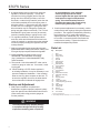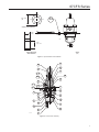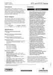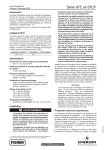
1
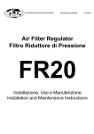
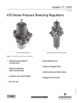
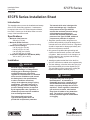
67CFS Series
Installation Sheet
Form 5756
January 2009
67CFS Series Installation Sheet
Introduction
This installation sheet covers the installation and startup
of the 67CFS Series filter regulators. If maintenance
is required, refer to the 67C Series Instruction Manual,
form 5469. Contact your local Sales Office to receive
a copy of the instruction manual.
Specifications
• Maximum Inlet Pressure:
250 psig (17,2 bar)
• Maximum Outlet Pressure:
50 psi (3,4 bar) over outlet pressure setting
• Outlet Pressure Ranges:
0 to 35 psig (0 to 2,4 bar)
0 to 60 psig (0 to 4,1 bar)
0 to 125 psig (0 to 8,6 bar)
0 to 150 psig (0 to 10,3 bar)
• Temperature Capabilities with Nitrile (NBR):
-40° to 180°F (-40° to 82°C)
Installation
The internal relief valve is designed for
minor seat leakage only. If maximum
inlet pressure to the Type 67CFSR
exceeds the maximum pressure ratings
of the downstream equipment or
exceeds the maximum allowable outlet
pressure of the Type 67CFSR, additional overpressure protection is required.
1. Regulator operation within ratings does not
preclude the possibility of physical damage from
external sources or debris in the lines. Regulators
should be inspected for damage periodically and
after an overpressure condition.
2. Only personnel qualified through training and
experience should install, operate, and maintain
a regulator. Make sure there is no damage to or
foreign material in the regulator and all tubing/
piping is free of debris.
3. Install the regulator so that flow is from the IN to
the OUT connection as marked on the regulator body.
!
Warning
Personal injury, property damage,
equipment damage, or leakage due to
escaping gas or bursting of pressure
containing parts may result if this
regulator is overpressured or is installed
where service conditions could exceed
the limits given in the specifications,
or where conditions exceed any
ratings of the adjacent piping or piping
connections. To avoid such injury or
damage, provide pressure relieving or
pressure limiting devices (as required
by the appropriate code, regulation, or
standard) to prevent service conditions
from exceeding those limits.
!
Warning
A regulator may vent some gas to
the atmosphere. In hazardous or
flammable gas service, vented gas may
accumulate and cause personal injury,
death, or property damage due to fire or
explosion. Vent a regulator in hazardous
gas service to a remote, safe location
away from air intakes or any hazardous
area. The vent line or stack opening
must be protected against condensation
or clogging.
D103076X012
The internal relief valve in the
Type 67CFSR regulator does not
provide full overpressure protection. 4. For best drainage, orient the drain valve (key 2) to
the lowest possible point on the dripwell (key 5).
This orientation may be improved by rotating the
dripwell with respect to the body (key 1).
www.emersonprocess.com/regulators
67CFS Series
5. A clogged
spring case vent hole may cause the
regulator to function improperly. To keep this
vent hole from being plugged (and to keep the
spring case from collecting moisture, corrosive
chemicals, or other foreign material) orient the vent
to the lowest possible point on the spring case or
otherwise protect it. Inspect the vent hole regularly
to make sure it is not plugged. Spring case vent
hole orientation may be changed by rotating the
spring case with respect to the body. The 1/4-inch
threaded NPT spring case vent may be remotely
vented by installing tubing or piping into the vent.
6. For regulator shutdown, install upstream block
and vent valves and downstream block and vent
valves (if required), or provide some other suitable
means of properly venting the regulator inlet and
outlet pressures.
7. Apply a good grade of pipe compound to the male
pipe threads before making connections, making sure
not to get the pipe compound inside the regulator.
8. Install tubing fitting or piping into the 1/4-inch threaded NPT inlet connection on the body (key 1) and into the 1/4-inch threaded NPT body outlet connection.
9. The second 1/4-inch threaded NPT outlet can be used for a gauge or other use. If not used, it must be plugged.
10. When installing a 67CFS Series regulator in
an existing installation, it may be necessary to use
spacers to adapt the installation. If the mounting
bolts are too long, place a spacer on the bolt. To
be sure the regulator is secure, the bolts should
have at least two full threads of engagement.
Startup and Adjustment
1. With
proper installation completed and
downstream equipment properly adjusted, slowly
open the upstream and downstream shutoff valve
(when used) while using pressure gauges to
monitor pressure.
!
Warning
To avoid personal injury, property damage,
or equipment damage caused by bursting
of pressure containing parts or explosion 2
of accumulated gas, never adjust the
control spring to produce an outlet
pressure higher than the upper limit of the
outlet pressure range for that particular
spring. If the desired outlet pressure is
not within the range of the control spring,
install a spring of the proper range.
2. If outlet pressure adjustment is necessary, monitor
outlet pressure with a gauge during the adjustment
procedure. The regulator is adjusted by loosening
the locknut (key 19), if used, and turning the
adjusting screw or handwheel (key 18) clockwise
to increase or counterclockwise to decrease the
outlet pressure setting. Tighten the locknut to
maintain the adjustment position.
Parts List
Key Description 1 Body
2 Drain Valve
3 Flange Screw
4(1) O-Ring
5 Dripwell
6(1) Filter Element
7 Spring Case
9 Filter Retainer
10(1, 2) Valve Cartridge
11(1, 2) Valve Plug
12(1, 2) Valve Spring
13(1, 2) Valve Retainer
14(1, 2) O-Ring
15(1, 2) Relief Valve Soft Seat
16(1) Diaphragm Assembly
17
Spring
18
Adjusting Screw
19
Locknut
20
Upper Spring Seat
23
1/4-Inch Pipe Plug (not shown)
25
Label
26(1) Filter Gasket
33
Closing Cap
34
Spacer
37
Thrust Washer
45
Vent Screen
1. Recommended Spare Part
2. Valve cartridge assembly includes keys 10, 11, 12, 13, 14, and 15.
67CFS Series
0.50
(13)
34
OD
Spacer outer diameter
IN
0.25
(6,4)
spacer
B2697
0.32
(8,1)
id
spacer width and
inner diameter
inches (mm)
Figure 1. Spacer Diameter and Installation
19
33
20
18
17
16 D
25
16 E
15
45
16 C
16 B
16 A
7
11
1
10
14
26
12
4
6
13
5
37
9
40C1728
2
Figure 2. 67CFS Series Assembly
3
67CFS Series
Industrial Regulators
Natural Gas Technologies
TESCOM
Emerson Process Management
Regulator Technologies, Inc.
Emerson Process Management
Regulator Technologies, Inc.
Emerson Process Management
Tescom Corporation
USA - Headquarters
McKinney, Texas 75069-1872 USA
Tel: 1-800-558-5853
Outside U.S. 1-972-548-3574
USA - Headquarters
McKinney, Texas 75069-1872 USA
Tel: 1-800-558-5853
Outside U.S. 1-972-548-3574
USA - Headquarters
Elk River, Minnesota 55330-2445 USA
Tel: 1-763-241-3238
Asia-Pacific
Shanghai, China 201206
Tel: +86 21 2892 9000
Asia-Pacific
Singapore, Singapore 128461
Tel: +65 6777 8211
Europe
Bologna, Italy 40013
Tel: +39 051 4190611
Europe
Bologna, Italy 40013
Tel: +39 051 4190611
Gallardon, France 28320
Tel: +33 (0)2 37 33 47 00
Middle East and Africa
Dubai, United Arab Emirates
Tel: +971 4811 8100
Europe
Selmsdorf, Germany 23923
Tel: +49 (0) 38823 31 0
For further information visit www.emersonprocess.com/regulators
The Emerson logo is a trademark and service mark of Emerson Electric Co. All other marks are the property of their prospective owners. Fisher is a mark owned by Fisher Controls, Inc., a
business of Emerson Process Management.
The contents of this publication are presented for informational purposes only, and while every effort has been made to ensure their accuracy, they are not to be construed as warranties or
guarantees, express or implied, regarding the products or services described herein or their use or applicability. We reserve the right to modify or improve the designs or specifications of such
products at any time without notice.
Emerson Process Management does not assume responsibility for the selection, use or maintenance of any product. Responsibility for proper selection, use and maintenance of any Emerson
Process Management product remains solely with the purchaser.
©Emerson Process Management Regulator Technologies, Inc., 2003, 2009; All Rights Reserved