1
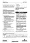
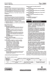
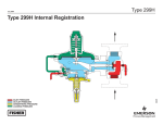
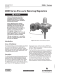
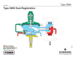
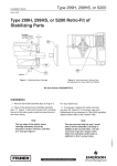
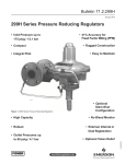
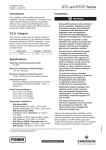
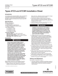
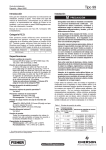
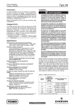
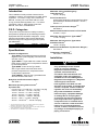
Installation Guide
English – September 2012
299H Series
This Installation Guide provides instructions for
installation, startup, and adjustment of 299H Series
regulators. To receive a copy of the Instruction
Manual, contact your local Sales Office or view
a copy at www.fisherregulators.com. For further
information refer to: 299H Series Instruction
Manual, form 5497, D102684X012.
P.E.D. Categories
This product may be used as a safety accessory
with pressure equipment in the following Pressure
Equipment Directive 97/23/EC categories. It may
also be used outside of the Pressure Equipment
Directive using sound engineering practice (SEP)
per table below.
product size
DN 40, 50 / NPS 1-1/2, 2
category
I
fluid type
1
Specifications
Available Configurations
Type 299H: Pilot-operated pressure reducing
regulator with a pilot integrally mounted to the
actuator casing
Type 299HR: A Type 299H with a token internal
relief valve to relieve minor overpressure caused
by thermal expansion
Type 299HS: Same as the Type 299H
with a Type VSX-2 slam-shut valve which
provides overpressure or overpressure and
underpressure protection
Type 299HSR: Same as the Type 299HS with
an internal token relief valve
Body Size and End Connection Styles
See Table 1
Maximum Operating Inlet Pressure(1)
by Orifice Size
6.4 x 9.5 mm / 1/4 x 3/8 inch – 12.1 bar / 175 psig
9.5 mm / 3/8 inch – 12.1 bar / 175 psig
13 mm / 1/2 inch – 12.1 bar / 175 psig
19 mm / 3/4 inch – 10.3 bar / 150 psig
22 mm / 7/8 inch(3) – 8.6 bar / 125 psig
25 mm / 1 inch(3) – 6.9 bar / 100 psig
30 mm / 1-3/16 inch(3) – 5.5 bar / 80 psig
1. The pressure/temperature limits in this Installation Guide and any applicable standard or code limitation should not be exceeded.
2. For optimum performance, a pilot supply regulator may be installed in the pilot
supply tubing between the main valve and pilot.
3. This orifice size is not available for Types 299HS and 299HSR.
Maximum Casing and Emergency
Outlet Pressure(1)
4.5 bar / 66 psig
Proof Test Pressure
All Pressure Retaining Components have been
proof tested per Directive 97/23/EC - Annex 1,
Section 7.4
Outlet (Control) Pressure Ranges(1)(2)
See Table 2
Minimum Differential Pressure For Full Stroke
0.10 bar / 1.5 psi
Maximum Set Pressure for Type 299HS(1)
1.1 bar / 16 psig
Maximum Set Pressure for Type VSX-2
Slam-Shut Device(1)
1.6 bar / 23 psig
Minimum and Maximum Trip Pressure Ranges(1)
See Table 3
Temperature Capabilities(1)
-29 to 66°C / -20 to 150°F
Installation
!
Warning
Only qualified personnel should
install or service a regulator.
Regulators should be installed,
operated, and maintained in
accordance with international and
applicable codes and regulations,
and Emerson Process Management
Regulator Technologies Inc. (Regulator
Technologies) instructions.
If the regulator vents fluid or a leak
develops in the system, it indicates that
service is required. Failure to take the
regulator out of service immediately
may create a hazardous condition.
Personal injury, equipment damage,
or leakage due to escaping fluid
or bursting of pressure-containing
parts may result if this regulator is
overpressured or is installed where
service conditions could exceed the
limits given in the Specifications
section, or where conditions exceed
any ratings of the adjacent piping or
piping connections.
www.fisherregulators.com
D102684XUS2
Introduction
299H Series
To avoid such injury or damage,
provide pressure-relieving or pressurelimiting devices (as required by
the appropriate code, regulation,
or standard) to prevent service
conditions from exceeding limits.
Additionally, physical damage to the
regulator could result in personal
injury and property damage due to
escaping fluid. To avoid such injury
and damage, install the regulator in a
safe location.
Clean out all pipelines before installation of the
regulator and check to be sure the regulator has
not been damaged or has collected foreign material
during shipping. For NPT bodies, apply pipe
compound to the external pipe threads. For flanged
bodies, use suitable line gaskets and approved
piping and bolting practices. Install the regulator
in any position desired, unless otherwise specified,
but be sure flow through the body is in the direction
indicated by the arrow on the body.
Note
It is important that the regulator be
installed so that the vent hole in the
spring case is unobstructed at all times.
For outdoor installations, the regulator
should be located away from vehicular
traffic and positioned so that water, ice,
and other foreign materials cannot enter
the spring case through the vent. Avoid
placing the regulator beneath eaves or
downspouts, and be sure it is above the
probable snow level.
Type VSX-2 Installation
!
Warning
If the Type VSX-2 is exposed to an
overpressure condition, it should be
inspected for any damage that may
have occurred. Operation below these
limits does not preclude the possibility
of damage from external sources or
from debris in the pipeline.
The Type VSX-2 may be shipped separately from
the regulator. To install the unit on a regulator, place
the new O-rings (keys 2 and 3, Figure 1) on the
Type VSX-2 and slide the module into the regulator
body. Secure the Type VSX-2 to the regulator body
with the four set screws (key 4). The unit may be
oriented in any direction with respect to the sensor
line connection.
2
Overpressure Protection
The recommended pressure limitations are
stamped on the regulator nameplate. Some type
of overpressure protection is needed if the actual
inlet pressure exceeds the maximum operating
outlet pressure rating. Overpressure protection
should also be provided if the regulator inlet
pressure is greater than the safe working pressure
of the downstream equipment.
Regulator operation below the maximum pressure
limitations does not preclude the possibility of
damage from external sources or debris in the
line. The regulator should be inspected for
damage after any overpressure condition.
Startup
The regulator is factory set at approximately the
midpoint of the spring range or at the pressure
requested, so an initial adjustment may be required
to give the desired results. With proper installation
completed and relief valves properly adjusted, slowly
open the upstream and downstream shutoff valves.
Adjustment
To change the outlet pressure, remove the closing
cap or loosen the locknut and turn the adjusting
screw clockwise to increase outlet pressure or
counterclockwise to decrease pressure. Monitor
the outlet pressure with a test gauge during the
adjustment. Replace the closing cap or tighten the
locknut to maintain the desired setting.
Type VSX-2 Trip Adjustment
Note
An adjustment tool is included with
the Type VSX-2. Use only this tool
to make adjustments to the unit. To
make adjustments, the overpressure
trip spring is found under the
outer adjusting screw and the
underpressure trip spring is found
under the inner adjusting screw.
To adjust the Overpressure Trip Spring:
1. Adjust the overpressure trip setting to its
maximum compression.
2. If present, adjust the underpressure spring to its minimum compression.
3. Backpressure the unit with the desired
overpressure trip pressure.
4. Reduce the overpressure trip spring
compression until the Type VSX-2 trips.
299H Series
Table 1. Body Sizes and End Connection Styles
BODY SIZE
BODY MATERIAL AND END CONNECTION STYLE
DN
Inch
Cast Iron
(For Types 299H and 299HR only)
Ductile Iron
Steel
(For Types 299H and 299HR only)
32
1-1/4
NPT
----
----
40
1-1/2
NPT
NPT
NPT
50
2
NPT and CL125 FF(1) flanged
NPT, CL125 FF, CL250 RF, and
PN 10/16 flanged
NPT, CL150 RF, and PN 16 flanged
1. This flange is available with a face-to-face dimension of 191 mm / 7.5 inches or 254 mm / 10 inches.
Table 2. Outlet Pressure Ranges
OUTLET (CONTROL) PRESSURE RANGE
Type
mbar
Inch w.c.
299H
299HR, 299HS, and 299HSR
9 to 15(1)
12 to 22(1)
17 to 50(1)
40 to 99(1)
3.5 to 6(1)
5 to 9(1)
7 to 20(1)
16 to 40(1)
X
X
X
X
X
X
X
X
69 mbar to 0.22 bar
0.19 to 0.41 bar
0.35 to 1.1 bar
0.97 to 2.4 bar
2.1 to 4.1 bar
1 to 3.25 psig
2.75 to 6 psig
5 to 16 psig
14 to 35 psig
30 to 60 psig
X
X
X
X
X
X
X
X
-------
1. Use a pilot supply regulator if actual inlet pressure varies more than ±1.4 bar / 20 psi and the published accuracy is required.
Table 3. Type VSX-2 High and Low Trip Pressure Ranges
SETPOINT
RANGES
High Pressure Trip
Low Pressure Trip
SLAM-SHUT TYPE
LP
LP
FOR USE WITH MAIN VALVE SPRING RANGE
mbar
Inch w.c.
9 to 15
3.5 to 6
12 to 22
5 to 9
9 to 15
3.5 to 6
12 to 22
5 to 9
17 to 50
7 to 20
17 to 50
7 to 20
40 to 99
16 to 40
40 to 99
16 to 40
69 mbar to 0.22 bar
1 to 3.25 psig
0.19 to 0.41 bar
2.75 to 6 psig
0.19 to 0.41 bar
2.75 to 6 psig
0.35 to 1.1 bar
5 to 16 psig
0.35 to 1.1 bar
5 to 16 psig
12 to 22
5 to 9
17 to 50
7 to 20
17 to 50
7 to 20
40 to 99
16 to 40
69 mbar to 0.22 bar
1 to 3.25 psig
0.19 to 0.41 bar
2.75 to 6 psig
0.19 to 0.41 bar
2.75 to 6 psig
0.35 to 1.1 bar
5 to 16 psig
MINIMUM TO MAXIMUM TRIP PRESSURE
mbar
Inch w.c.
30 to 62
12 to 25
50 to 129
20 to 52
97 to 269
1.4 to 3.9 psig
262 to 600
3.8 to 8.7 psig
400 to 1103
5.8 to 16 psig
800 to 1586
11.6 to 23 psig
5 to 30
2 to 12
10 to 75
4 to 30
25 to 159
0.36 to 2.3 psig
103 to 745
1.5 to 10.8 psig
Note: Other spring combinations are available, please contact your local Sales Office for additional information.
3
299H Series
To adjust the Underpressure Trip Spring:
1. Adjust the underpressure trip spring back to its
minimum compression.
2. Backpressure the unit with the desired
underpressure trip pressure.
3. Increase the underpressure trip spring
compression until the Type VSX-2 trips.
Taking Out of Service (Shutdown)
!
Warning
To avoid personal injury resulting from
sudden release of pressure, isolate
the regulator from all pressure before
attempting disassembly.
The seal and warning tag contain
important safety information, if removed
be sure to reattach before startup.
Parts List
Type VSX-2 Slam-Shut Device
(Figure 1)
Key Description
1
2*
3*
4
6
7
8
10
11*
12
13
Type VSX-2 Module
Upper O-ring
Lower O-ring
Set Screw
Type Y602-12 Vent Assembly
High-Pressure Control Spring
Low-Pressure Control Spring
Machine Screw
Gasket
Adjustment Tool
Pipe Plug
P590 Series Filter (Figure 2)
Key Description
1
2* 3
4
5
6
7*
Filter Body
Filter Element
Filter Head
Machine Screw
Washer
Spring Washer
Gasket
299H Series Regulator
(Figures 3 through 6)
Key Description
1
2
3
4
Lower Casing
Upper Casing
Closing Cap
Spring Seat
*Recommended spare part
4
299H Series Regulator
(Figures 3 through 6) (continued)
Key Description
5
6
7
8*
9*
10
11
12
13*
14*
15*
16
17
18
19
20
21
22
23
24
25
26
27
28
29
30
31
32
33
34
35
36
37
38
39
40
41
42
43
44
45
46
47
48
49*
50
51
52*
53*
54*
56
57
58
59
61
62
63
68*
69
70
80
81
82
83
84
85
86
87
88
89
93
Adjustment Nut
Closing Spring
Pressure Equalization Spring
Diaphragm
O-ring
Diaphragm Post
Pusher Post
Orifice
Disk
O-ring
O-ring
Valve Stem Assembly
Valve Body
Cap Screw
Elbow
Connector
Pilot Supply Tubing (Without Filter)
Loading Tubing
Cap Screw
Machine Screw
Lever Pin
Lever
Vent Hood (Type Y602-12 Vent Assembly)
Diaphragm Assembly
Closing Cap
Machine Screw
Spring Case
Control Spring
Spring Seat
Bonnet
Locknut
Adjusting Screw
Hex Nut
Washer
Diaphragm Post
Pusher Post
Overtravel Spring
Machine Screw
Rivet
Retaining Ring
Check Valve Assembly
Machine Screw
Inlet Fitting
Stem Assembly
O-ring
Pilot Orifice
Inlet Screen
Pilot Disk Assembly
O-ring
O-ring
Screw
Lever
Pipe Plug
Pipe Plug, Internal Registration only
O-ring
Drive Screw
Nameplate
Wire Seal
Warning Tag, Aluminum
Bleed Restriction
Pad
Diaphragm Head
Insert (For Types 299HS and 299HSR only, see Figure 1)
O-ring (For Types 299HS and 299HSR only, see Figure 1)
Plate (For Types 299H and 299HR only)
O-ring (For Types 299H and 299HR only)
O-ring (For Types 299H and 299HR only)
Set Screw (For Types 299H and 299HR only)
Spring Seat (For Types 299HR and 299HSR only)
Label
Spring Seat Washer
299H Series
82 83
VIEW A
view a
T80423
view a
NOTE: FOR KEYS 82 AND 83, REFER TO 299H SERIES REGULATORS PARTS LIST.
Figure 1. Type VSX-2 Assembly
6
5
2
5
7
1
4
3
A7008
Figure 2. Optional P590 Series Filter
5
299H Series
T80391-6
Type 299h PILOT WITHOUT rELIEF vALVE
T80391-6
Type 299hR PILOT WITH TOKEN rELIEF vALVE
Figure 3. 299H Series Pilot Assemblies
T80391-2
T80391-4
External Registration
T80391-3
Dual Registration
Figure 4. 299H Series Registration Assemblies
6
internal Registration
299H Series
93
T80391
SEE FIGURE 4
T80391-7
299H Series Pilot Trim
Figure 5. 299H Series Interior Assembly
7
299H Series
T80391-1
T80391-1
Figure 6. 299H Series Exterior Assembly
Industrial Regulators
Natural Gas Technologies
TESCOM
Emerson Process Management
Regulator Technologies, Inc.
Emerson Process Management
Regulator Technologies, Inc.
Emerson Process Management
Tescom Corporation
USA - Headquarters
McKinney, Texas 75069-1872, USA
Tel: +1 800 558 5853
Outside U.S. +1 972 548 3574
USA - Headquarters
McKinney, Texas 75069-1872, USA
Tel: +1 800 558 5853
Outside U.S. +1 972 548 3574
USA - Headquarters
Elk River, Minnesota 55330-2445, USA
Tels: +1 763 241 3238
+1 800 447 1250
Asia-Pacific
Shanghai 201206, China
Tel: +86 21 2892 9000
Asia-Pacific
Singapore 128461, Singapore
Tel: +65 6770 8337
Europe
Selmsdorf 23923, Germany
Tel: +49 38823 31 287
Europe
Bologna 40013, Italy
Tel: +39 051 419 0611
Europe
Bologna 40013, Italy
Tel: +39 051 419 0611
Chartres 28008, France
Tel: +33 2 37 33 47 00
Asia-Pacific
Shanghai 201206, China
Tel: +86 21 2892 9499
Middle East and Africa
Dubai, United Arab Emirates
Tel: +971 4811 8100
For further information visit www.emersonprocess.com/regulators
The Emerson logo is a trademark and service mark of Emerson Electric Co. All other marks are the property of their prospective owners. Fisher is a mark owned by Fisher Controls International LLC,
a business of Emerson Process Management.
The contents of this publication are presented for informational purposes only, and while every effort has been made to ensure their accuracy, they are not to be construed as warranties
or guarantees, express or implied, regarding the products or services described herein or their use or applicability. We reserve the right to modify or improve the designs or specifications
of such products at any time without notice.
Emerson Process Management Regulator Technologies, Inc. does not assume responsibility for the selection, use or maintenance of any product. Responsibility for proper selection, use
and maintenance of any Emerson Process Management Regulator Technologies, Inc. product remains solely with the purchaser.
©Emerson Process Management Regulator Technologies, Inc., 2002, 2012; All Rights Reserved