1
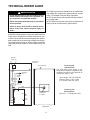
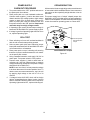
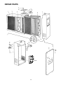
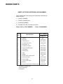
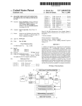
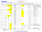
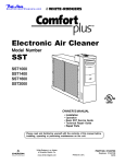
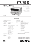
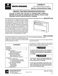
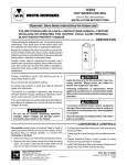
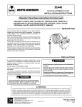
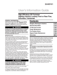
by White-Rodgers
Electronic Air Cleaner
UST
Universal Slim Twin
DGERS
WHITE-RO
SLIM TWIN
UNIVERSALAIR
CLEANER
ELECTRONIC
OPERATING
LIGHT
Model Number
16C26S-010
OFF
ON
OWNERS MANUAL
•
•
•
•
•
Installation
Operation
Basic UST Service Guide
Technical Repair Guide
Repair Parts
Please read and familiarize yourself with the contents of this manual
before installing, operating or performing maintenance on the unit.
UL Listed
CSA Certified
Printed In U.S.A.
Part No. 37-6070A
Replaces 846-2027 Rev B
0015
1. Read the Owners Manual and the Rules for Safe
Operation carefully. Failure to follow these rules and
instructions could cause a malfunction of filter or
unsatisfactory service.
2. Follow a regular service and maintenance schedule
for efficient operation.
RULES FOR SAFE
INSTALLATION
AND OPERATION
Please read instructions before installing and using the
Electronic Air Cleaner. This will help you obtain the full
benefit from the Electronic Air Cleaner you have selected.
!
!
Installation of this unit must comply with local
electric codes or other applicable codes.
WARNING
Review and understand local codes prior to installation.
ELECTROCUTION HAZARD
Shut off power at fuse panel before
servicing.
Failure to do so could result in serious personal
injury or death.
Failure to do so could result in
serious personal injury or death.
!
WARNING
!
CAUTION
CABINET AND CELLS MAY CONTAIN SHARP EDGES.
WARNING
Do not attempt installation of this unit unless you
are familiar with the necessary tools, equipment,
utility connections and potential hazards.
Use care when servicing unit or handling cells.
Installation should be performed only by a qualified service provider.
Failure to do so could result in minor personal injury.
Failure to do so could result in reduced performance of the unit, serious personal injury or
death.
TABLE OF CONTENTS
AIR CLEANER SIZE
Rules for Safe Installation and Operation ....... 2
How the Air Cleaner Works ............................ 3
Construction of the Air Cleaner....................... 3
Preinstallation ................................................. 4
Installation ....................................................... 6
Wiring Instructions .......................................... 7
Operation ........................................................ 8
Maintenance and Washing ............................. 8
Specifications .................................................. 9
Basic UST Service Guide ............................. 10
Technical Repair Guide ................................ 11
Repair Parts .................................................. 14
Your new air cleaner is designed for central heating or
cooling blowers delivering 1000 to 2000 cubic feet of air
per minute (cfm.)
BASIC TOOL REQUIRED
Tin Snip
Screwdriver
Rule or Tape Measure
Drill
2
HOW THE AIR CLEANER
WORKS
A
Dirt particles flowing through the ducts (Figure 1) first
enters the pre-filters (A) where large particles (hair, lint,
etc.) are trapped. Smaller particles (smoke, dust, pollen,
etc.) pass through these pre-filters and enter the ionizing
section (B). Here each tiny particle receives a positive
electrical charge. These charged particles then enter the
collecting section (C). This section consists of a series of
aluminum plates which are alternately charged negative
and positive.
B
C
Dirty Air In
The positive charge of the particles cause them to be
repelled by the positive plates and attracted to the negative plates where they are collected . . . just as a magnet
attracts iron filings.
Clean Air Out
Figure 1
Clean-filtered air re-enters the supply duct system.
CONSTRUCTION OF THE
AIR CLEANER
Not only is your air cleaner easy to install, it is also easy
to operate and maintain. Its basic components, and their
functions, are as follows: (See Figure 2)
Cabinet
Cabinet - mounts to existing duct work and houses the
collecting cells and pre-filters.
Pre-Filters
Handle
Collecting Cells - are made in two sections and perform
the actual collecting of dust, dirt, and other impurities from the air. They contain the ionizing and
collection sections described above.
Each cell must be installed with the ionizing wires
on the air entering side. Each cell must be oriented with the handles and contact button (Figure 2) toward the operator.
Contact
Button
Pre-filters - are in two sections which are interchangeable. They serve as a pre-filter to trap large
particles such as hair and lint before they can
enter the cell sections.
Collecting Cells
Figure 2
Power Pack- contains operating and power on lights as
well as the solid state components that convert
the 120 volt power supply to the high-voltage,
direct current required for the collecting cell.
3
Contact
Button
Power Pack
PREINSTALLATION
Not to Exceed 20°
(Interchangeable) (Interchangeable)
Collecting Cell
Collecting Cell
Outlet Box
Cabinet
Power Pack
Handle
Air Flow
Air Flow
Furnace
Opening
Electronic
Air Cleaner
Opening
Furnace
Transition Section
(if Needed)
Contact
Button
Pre-Filters
(Interchangeable)
Electronic
Air Cleaner
Contact
Button
See text for Cell
Removal Clearance
Figure 4
Figure 3
LOCATING THE AIR FILTER
Your electronic air cleaner must be mounted in the return
air duct of a central forced-air system, on the air entering
side of your furnace. (See Figure 3 for example.)
Knockouts for
3/4" Conduit
(three sides)
6 7/8"
Select a location that meets the following:
1. The face of the cell will be at a right angle to the air
stream.
2. Allow a clearance of 14 inches to permit removal of
cells and pre-filters: (See Figures 4 and 5).
For complete dimension data refer to Figure 5.
3. The air filter is not to be placed in the discharge of
either the heating or cooling unit.
4. IMPORTANT: If atomizing spray type humidifier is
used, it must be installed downstream from the air
filter.
If furnace opening cannot be enlarged to required size, a
transition sheet metal section must be used. Transition
must be planned for each job. Reduction should not be
more than 4 inches per linear foot, approximately 20
angular degrees (Figure 3).
18 5/8"
20 5/8"
20 3/8"
17 3/4"
21 5/1
6"
25 1/2
"
DIRECTION OF AIR FLOW THROUGH THE
AIR CLEANER
Figure 5
Your air cleaner is shipped from the factory with air flow
from left-to-right. If this air flow is suitable for the installation, no further changes need to be made (Figure 4). For
right-to-left air flow, remove both pre-filter and cell sections. Turn cells upside down (with the same end facing
the cabinet opening). This will locate the ionizing wires at
the right, and both contact buttons and cell handles will be
facing the power door. Air flow direction must agree with
arrow embossed on end of collecting cells.
After installing the cell sections, install pre-filters in cabinet tracks on the right. This will again place the pre-filters
on the air entering side (on the same side as ionizing
wires).
4
TYPICAL MOUNTING POSITIONS
Air Flow
Air Flow
Air Flow
Rear View
Rear View
Figure 6
Figure 8
Figure 7
BASEMENT FURNACE
(LOWBOY) (Figure 6)
HIGHBOY FURNACE
(Figure 8)
COUNTERFLOW
FURNACE (Figure 7)
Cleaner is mounted horizontally in return plenum,
just above furnace.
Cleaner is mounted horizontally in return duct or plenum,
just above furnace.
Side installation. Cleaner
is mounted vertically,
where return air enters
side inlet of furnace.
HIGHBOY FURNACE
(Figure 9)
Installation beneath furnace.
Cleaner mounts horizontally,
where return air enters from
below. Raise furnace and install beneath base.
Less than
7 Inches
Offset
At Least
9 Inches
Air Flow
Figure 10
OFFSET INSTALLATION
(Figure 10)
Figure 9
Typical use of duct offset to match air filter opening.
If duct connection to furnace allows less than nine
inches for mounting the air cleaner, shorten the
lateral trunk, or attach an offset fitting to the elbow.
Air Flow
HORIZONTAL FURNACE
(Figure 11)
Cleaner is mounted vertically
in the return duct near furnace.
Figure 11
5
INSTALLATION
REMOVE OLD FILTER AND DISCARD
(Figure 12)
NOTE: This filter may be mounted in the furnace compartment.
CLEAN BLOWER COMPARTMENT
Figure 12
It is suggested that the furnace blower compartment,
blower and blower housing be cleaned to ensure clean air
circulation.
INSTALLATION
Frame
Duct
The following is a typical installation of the air cleaner on
a “Highboy” furnace (Figure 8).
1. Place the air filter cleaner on the floor. Stand it upright
with the power door facing you (Figure 4). If a horizontal installation is being planned, lay the cleaner on its
side, this will help you to visualize the relative location
of all parts.
Allow ample space for wiring and servicing the power
supply box (Figure 13).
2. Release the latch, remove the power pack (by grasping handle and pulling power pack away from cabinet) and set it aside. Remove the collecting cells and
pre-filters. Set pre-filters and cells aside in a safe
location until the cabinet is installed.
3. Set the cabinet next to the furnace. If necessary,
enlarge the opening in the furnace (if possible) to
match the opening in the cabinet.
If the furnace opening cannot be enlarged, a transition fitting should be used. (Figure 3).
The cabinet can be attached directly (Figure 13), or a
starting collar can first be fitted to the furnace inlet. A
butt or slip joint can be used.
Securely attach the cabinet to furnace inlet, using at
least two of the mounting holes on each side of the
cabinet.
4. Using butt joint, attach duct work (normally an elbow)
to the upstream side of air cleaner cabinet. (Note the
use of the sheet metal turning vanes inside the elbow
to improve air distribution over the face of the cells.)
(Figure 14)
NOTE: An optional method of attaching duct work to the
cabinet is to modify the cabinet (Figure 15) by bending the
tabs outward at a 90° angle and attaching duct work to
tabs.
Power
Supply
Box
Mounting
Holes
Figure 13
Air Flow
Turning
Vanes
Figure 14
Optional method
(Bend tabs outward at 90° angle)
Figure 15
5. Connect the vertical duct section to the elbow. Wedge
a wood block between floor and elbow for support
(Figure 16).
6. Seal all joints in the return air system downstream
from the air cleaner with duct tape to prevent dust
from entering the air stream. Tape is usually applied
on the outside of ducts, but may also be applied on the
inside, or both.
Transition Fittings
If the air duct does not fit the cabinet opening, a transition
fitting should be used. Gradual transitions are preferred
for greatest efficiency. Not more than four inches per
linear foot (approximately 20° angle) should be allowed
(Figure 3).
6
your system is not equipped with an EAC output
terminal, Figure 19 shows a method for installing a
relay (customer supplied) to switch power to the air
cleaner when the blower is on.
WIRING INSTRUCTIONS
7. With the cabinet installed, the air cleaner can now be
wired to electrical input source.
Floor
!
WARNING
Installation of this unit must comply with local
electric codes or other applicable codes.
Review and understand local codes prior to installation.
Conduit
Failure to do so could result in serious personal
injury or death.
8. The air cleaner must be wired through the furnace
controls. This unit requires a 120 VAC 60 Hz input
circuit. A 20 amp circuit is more than adequate.
9. Remove junction box cover and install the required
bushing into the 3/4 in. knock out. With the supply
voltage turned off, route three (3) wires into junction
box for connections. (See Fig. 17.)
Insure all wires are clamped, wire connectors properly installed and grommets used to prevent wire
abrasion.
10. The air cleaner must be wired to have power supplied
when the furnace blower is on and there is airflow
through the duct. Some furnace control modules
have an output terminal for an electronic air cleaner
that will energize the unit when the blower is on. If
Duct
Electronic
Air Cleaner
Figure 18
Cooling Fan
Relay
(External)
Electronic
Air Cleaner
N.C.
Hi
Vertical
Section
N.C.
Brown
N.O.
Tape All
Joints
Black
N.O.
120 Volt
60 Hz
120 Volt
2 Speed
Fan
N.O.
N.C.
C
Lo
N.O.
120 Volt
Relay (OFF)
(Customer
Supplied)
Fan Control
(Open)
120 Volt
60 Hz
Cooling Mode - Fan Operating in Hi Speed
Cooling Fan
Relay
(External)
Wood Block
Electronic
Air Cleaner
Figure 16
N.C.
Hi
N.C.
Hot
Hot
Brown
Grounding
Conductor
N.O.
Front View
Black
N.O.
120 Volt
60 Hz
Fan Control
(Closed)
120 Volt
2 Speed
Fan
N.O.
N.C.
C
Lo
N.O.
120 Volt
Relay (ON)
(Customer
Supplied)
120 Volt
60 Hz
Heating Mode - Fan Operating in Low Speed
Figure 17
Figure 19
7
An alternate method for controlling the air cleaner
operation is to install an F859-0381 Air Flow Switch/
Harness Kit (available separately) that switches power
to the air cleaner when airflow is detected.
NOTE: The air cleaner should not be operating unless the furnace blower is on.
11. With the cabinet Installed, reinstall pre-filter(s) and
collecting cell(s) (Figure 20).
NOTE: The contact button and handles on the cell
must be facing you and ionizing wires must be on the
air intake side.
12. Install the power pack as follows:
Engage the lip on lower inside edge of power pack in
the flange on cabinet and carefully close the power
pack, making sure that the electrical connector prongs
on the power pack enter the slots in the socket on
cabinet. When the power pack is fully in place, engage the latch and snap it closed.
Cabinet
Pre-Filters
Handle
Contact
Button
Collecting Cells
Contact
Button
Power Pack
Figure 20
OPERATION
1. With the 120 VAC power turned on at the circuit
breaker for the furnace, push the air cleaner ON-OFF
switch to the “ON” position (Figure 21).
2. With the furnace blower running, the air cleaner will
be operating. An arcing or “snapping” sound may be
heard. This will occur occasionally, however the unit
is operating properly.
3. With the furnace blower running, the Operating Light
should be ON. If the Operating Light is not ON this
signifies that the cells need washing, or that trouble
exists in the unit.
If, after washing the cells, the Operating Light stays off,
the cell could be wet, improperly placed in the cabinet or
may need servicing.
Operating
Light
On-Off
Switch
NOTE: An occasional flicker of the light accompanied by
harmless sparking or snapping noise may occur. This is
caused by trapping large particles of dirt. If arcing is
continuous, the cells should be washed or checked for
service problems see Basic UST Service Guide.
Figure 21
MAINTENANCE AND
WASHING
!
For maximum efficiency your air cleaner cell(s) and prefilter(s) should be inspected once a month and cleaned
when necessary. Cleaning will usually be required every
one to three months, depending upon the particular
household circumstances. When cleaning is required the
following procedure should be used:
CAUTION
CABINET AND CELLS MAY CONTAIN SHARP EDGES.
CLEANING THE CELLS
1. Turn the air moving system “OFF.”
2. Push the ON-OFF switch on the power pack to the
“OFF” position (Figure 21). Wait 15 seconds and both
the power pack and the collecting cell(s) will be
automatically discharged.
Use care when servicing unit or handling cells.
Failure to do so could result in minor personal injury.
8
3. Release the latch on top of power pack and pull the
power pack straight away from cabinet at the top.
Then lift pack out of ledge at bottom edge of cabinet.
Set power pack aside.
4. Remove the cell(s) and pre-filter(s) from cabinet.
Using a solution of warm water and low sudsing
detergent, soak cell(s) and pre-filter(s) for 20 to 30
minutes.
NOTE: Ionizing wires may become coated causing
loss of cleaning ability by the collecting cell. Using a
damp cloth, wipe each ionizing wire, exercising care
not to damage them.
5. Remove the cell(s) and pre-filter(s) from solution and
rinse thoroughly with clean water.
6 Allow cell(s) and pre-filter(s) to drip dry for a minimum of 2 hours. Cell(s) and pre-filter(s) may be
tipped at a slight angle to expedite the drip-dry process.
7. Reinstall the cell(s) and pre-filter(s) in the cabinet.
8. Replace the power pack. Turn furnace fan on. After
30 minutes push ON-OFF switch on the power pack
to the “ON” position.
A moderate amount of arcing or “snapping” may
occur at this time, which will indicate that the cell(s)
are still damp. If the noise is objectionable, push the
ON-OFF switch to the “OFF” position and allow
additional time for cell(s) and pre-filter(s) to dry. In
some cases the Operating Light will remain OFF
during this initial activation of the air cleaner, and this
would indicate that the cell(s) are not completely dry.
The Operating Light should remain ON while the
furnace fan is running once the drying is complete.
REPLACING AN IONIZING WIRE
If an ionizing wire should break, it can be replaced as
follows:
1. Remove all pieces of broken wire. Make sure supports at each end are in good condition and not bent
out of shape.
2. Hook the new wire onto the support at one end.
3. Hold your finger against the support at the other end
(Figure 22) and hold the ionizing wire between thumb
and forefinger as shown or use needle nose pliers.
Press inward on spring support. Hook end of wire
over small tab at end of support and release. Make
sure wire is securely anchored at each end.
Support
Ionizing
Wire
Figure 22
SPECIFICATIONS
SPECIFICATIONS FOR 16C26S-010
Rated Capacity
1000 - 2000 cfm
Max. Pressure Drop
.12 in. W.G.
Cell Weight
(2) 9 lbs. each
Power Pack Weight
9 lbs.
Unit Weight
37 lbs.
Power Consumption
40 Watts (Max)
Electrical Input
120 VAC 60 hz.
Electrical Output
@ 6450 VDC (nom)
1.5 Ma
Max. Ozone Output
.05 ppm
Temperature Rating
40° F to 125° F
9
BASIC UST SERVICE GUIDE
This guide will cover most homeowner complaints. If, after checking the items listed, the unit still fails to operate
properly, contact the nearest Authorized Service Center.
SERVICE INDICATION
SERVICE CHECKS
ON/OFF switch “ON”
Blower ON
Operating Light ON
Unit functioning Normally
ON/OFF switch “ON”
Blower ON
Operating Light OFF
1. Power is not being supplied to air cleaner.
A. Check fuse or circuit breaker.
B. Ensure power pack is properly installed and latched.
2. Collecting cell shorted - Turn power Off - Remove power pack - Remove
collecting cells - Replace power pack - Restore power (ensure blower is
operating).
A. If Operating Light comes ON check cells for bent plates, loose ionizing
wire(s) or cracked insulator(s).
B. If Operating Light remains OFF, malfunction is in the power pack. (See
power supply Checkout Procedure).
Excessive arcing during
normal operation Operating Light may blink
1. Wet collecting cell.
A. Allow cell(s) to dry after cleaning before applying power.
2. Damaged collecting cell(s).
A. Remove cell(s) and inspect for bent plates, loose ionizing wire(s), cracked
insulator(s), etc.
3. Collecting cells dirty.
A. Clean cells as instructed in this manual.
4. Faulty power supply (see power supply checkout procedure)
10
TECHNICAL REPAIR GUIDE
!
All voltage measurements indicated can be made with a
high voltage D.C. probe and a general purpose volt ohm
meter. For example: Simpson 260 or equivalent.
WARNING
Do not attempt repair of this unit unless you are
familiar with the necessary tools, equipment, utility connections and potential hazards.
NOTE: All tests to be performed with the Ozone Reduction Jumper intact.
NOTE: When servicing the power pack components, all
wiring must be routed to factory specifications.
Repair should be performed only by a qualified
service provider.
Failure to do so could result in reduced performance of the unit, serious personal injury or
death.
This guide contains service checks to assist service
personnel in locating and correcting any malfunction that
might occur to render the air cleaner ineffective or inoperative. The air cleaner has been designed with replaceable components, such as the high-voltage power supply.
This allows the serviceman to replace a faulty component
rather than attempt repairs of such components in the
field.
120 VAC
Connector
L1
L2
Power Pack
Assembly
Cover Assembly
Power Supply
Specifications
The solid-state power supply is not
designed for individual component part
replacement and must be replaced as
a complete "snap-in" unit.
Operating
Light
ON/OFF
Switch
Blu
Wht
Blk
Wht
Input voltage: 120 VAC 50/60 Hz.
Output to light: 1.5 to 2.5 VDC
H.V. Output: 6450 VDC (nom)
Blk
Red
Gnd
Collecting Cell
Specifications
Cell Contact
& Insulator
Power
Supply
Figure 23
11
1600 cfm - 1.5 Ma @ 6450 VDC
POWER SUPPLY
CHECKOUT PROCEDURE
OZONE REDUCTION
All electronic air cleaners typically produce a small amount
of ozone that is within established limits. Some customers
may notice an odor especially at high altitudes or low air
flow rates.
1. Turn power switch to the “OFF” position and remove
the power pack from cabinet.
2. Place power pack on a well insulated workbench.
Connect meter negative (-) lead to the sheet metal
chassis and the high voltage probe to high voltage
contact on back cover of power pack. Connect AC
power to power pack using an extension cord and
turn power switch to the “ON” position. Keep hands
and tools away from high voltage contact.
3. If Operating Light comes ON and output voltage is
between 6100 and 6800 VDC, power supply is good.
4. If voltage is good but Operating Light does not come
on, replace Operating Light.
This power supply has a “hairpin” shaped jumper wire
labeled W1 (see Fig 24) that can be cut and separated in
case of such complaints. This will cause the power supply
to limit the maximum operating power to a lower level.
W1
CELL TEST
Cut and separate
Ozone Reduction
Jumper
1. Place collecting cell on a well insulated workbench
with the cell contact button pointing upward.
2. Select a power pack (with ozone reduction jumper
intact) that reads between 6100 and 6800 VDC at the
cell contact with no cell attached.
3. Place power pack on top of collecting cell ensuring
that there is proper contact between the cell contact
on the power pack contact.
4. Using a standard extension cord, apply 120 VAC to
power pack. Turn power switch to “ON” position.
5. Connect meter negative (-) lead to metal frame of
collecting cell. Use high voltage probe to measure
voltage at collecting cell ionizer or cell plates. Voltage
should be 6100 to 6800 VDC**.
NOTE: A new “out-of-box” cell may cause the voltage
to be lower than normal for a short period of time. To
obtain a more accurate measurement, “age” the cell
by applying high voltage to the cell for 15 to 30
minutes.
6
If voltage is below 6100 VDC, check cell for foreign
objects, bowed/bent/loose plates, broken ionizing
wires or cracked insulators. Wash cells if required. If
Operating Light remains OFF, replace collecting cell.
WHT/BRN
E3
BLK
LINE
E2
Ozone Reduction Jumper
Figure 24
12
NOTES
13
REPAIR PARTS
14
REPAIR PARTS
PARTS LIST FOR ELECTRONIC AIR CLEANERS
When ordering repair parts, always give the following information as
shown in this list.
1. The PART NUMBER
2. The PART DESCRIPTION
3. The MODEL NUMBER
4. The NAME OF ITEM - Electronic Air Cleaner.
Always order by “PART NUMBER” . . . Not by “ITEM NUMBER”
ITEM
NO.
DESCRIPTION
PART NUMBER
16C28S-010
1
Cabinet
2
Pre-Filter
• F825-0337
3
Collecting Cell
• F811-0321
4
Junction Box Cover
5
N/A
F838-0072
* Screw #6 x 3/8
------
6
Connector, Female
F818-0053
7
Power Pack Assembly
F858-0921
8
Cell Handle
F832-0039
9
Ionizing Wire
F843-0500
10
Light
F844-0131
11
Switch
F876-0202
12
Power Pack, Cabinet Only
13
Connector, Male
F827-0026
14
Power Supply
F858-1000
15
Cover, Power Pack
F820-0220
16
† Manual
17
† Charcoal Filter (with mounting clips)
N/A
37-6070
* Standard Hardware Item
• Two (2) Required
† Not Shown
15
• F825-0468
NOTICE TO CONSUMERS
White-Rodgers
Electronic Air Cleaner
Dear Consumer;
White-Rodgers would like to thank you for purchasing a White-Rodgers Electronic Air
Cleaner or product containing a White-Rodgers Electronic Air Cleaner. Although WhiteRodgers does not extend a warranty directly to consumers, White-Rodgers does extend a
warranty to Wholesalers and Original Equipment Manufacturers who use White-Rodgers
Products. To obtain more information about how your Wholesaler or Original Equipment
Manufacturer’s warranty may benefit you, please contact your Wholesaler or Original
Equipment Manufacturer.
Sincerely,
White-Rodgers
Controlling America’s Indoor Comfort
White-Rodgers Division, Emerson Electric Co.
9797 Reavis Road, St. Louis, MO 63123-5398
314-577-1300 • FAX 314-577-1517
www.white-rodgers.com