1
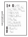
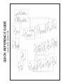
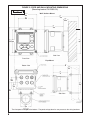
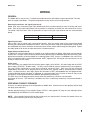
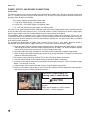
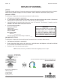
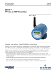
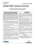
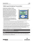
Instruction Sheet
PN 51A-1056/RevB
November 2010
Model 1056
Dual-Input Intelligent Analyzer
For additional information, please refer to Instruction Manual 51-1056, rev H
or visit www.emersonprocess.com/raihome/liquid
ESSENTIAL INSTRUCTIONS
READ THIS PAGE BEFORE PROCEEDING!
Your instrument purchase from Rosemount
Analytical, Inc. is one of the finest available for your
particular application. These instruments have been
designed, and tested to meet many national and
international standards. Experience indicates that its
performance is directly related to the quality of the
installation and knowledge of the user in operating
and maintaining the instrument. To ensure their continued operation to the design specifications, personnel should read this manual thoroughly before
proceeding with installation, commissioning, operation, and maintenance of this instrument. If this
equipment is used in a manner not specified by the
manufacturer, the protection provided by it against
hazards may be impaired.
• Failure to follow the proper instructions may
cause any one of the following situations to occur:
Loss of life; personal injury; property damage;
damage to this instrument; and warranty invalidation.
• Use only factory documented components for repair.
Tampering or unauthorized substitution of parts and procedures can affect the performance and cause unsafe
operation of your process.
• All equipment doors must be closed and protective covers must be in place unless qualified personnel are performing maintenance.
• If this equipment is used in a manner not specified by the
manufacturer, the protection provided by it against hazards may be impaired.
WARNING
RISK OF ELECTRICAL SHOCK
Equipment protected throughout by double insulation.
• Installation and servicing of this product may expose personel
to dangerous voltages.
• Main power wired to separate power source must be
disconnected before servicing.
• Do not operate or energize instrument with case open!
• Ensure that you have received the correct model
and options from your purchase order. Verify that
this manual covers your model and options. If
not, call 1-800-854-8257 or 949-757-8500 to
request correct manual.
• Signal wiring connected in this box must be rated at least
240 V.
• For clarification of instructions, contact your
Rosemount representative.
• Unused cable conduit entries must be securely sealed by
non-flammable closures to provide enclosure integrity in
compliance with personal safety and environmental protection
requirements. Unused conduit openings must be sealed with
NEMA 4X or IP65 conduit plugs to maintain the ingress
protection rating (NEMA 4X).
• Follow all warnings, cautions, and instructions
marked on and supplied with the product.
• Use only qualified personnel to install, operate,
update, program and maintain the product.
• Educate your personnel in the proper installation,
operation, and maintenance of the product.
• Install equipment as specified in the Installation
section of this manual. Follow appropriate local
and national codes. Only connect the product to
electrical and pressure sources specified in this
manual.
• Non-metallic cable strain reliefs do not provide grounding
between conduit connections! Use grounding type bushings
and jumper wires.
• Electrical installation must be in accordance with the National
Electrical Code (ANSI/NFPA-70) and/or any other applicable
national or local codes.
• Operate only with front panel fastened and in place.
• Safety and performance require that this instrument be
connected and properly grounded through a three-wire
power source.
• Proper use and configuration is the responsibility of the user.
Provide a switch or breaker to disconnect the analyzer from the main power supply. Install the switch or breaker
near the analyzer and label it as the disconnecting device for the analyzer.
QUICK START GUIDE
Model 1056 Dual Input Analyzer
1. Refer to mechanical installation instructions.
2. Wire sensor(s) to the signal boards. See wiring instructions. Refer to the sensor instruction sheet for additional details. Make current output, alarm relay and power connections.
3. Once connections are secured and verified, apply power to the analyzer.
WARNING
RISK OF ELECTRICAL SHOCK
Electrical installation must be in accordance with
the National Electrical Code (ANSI/NFPA-70)
and/or any other applicable national or local codes.
4. When the analyzer is powered up for the first time, Quick Start screens appear. Quick Start operating tips
are as follows:
a. A backlit field shows the position of the cursor.
b. To move the cursor left or right, use the keys to the left or right of the ENTER key. To scroll up or down
or to increase or decrease the value of a digit use the keys above and below the ENTER key . Use the
left or right keys to move the decimal point.
c. Press ENTER to store a setting. Press EXIT to leave without storing changes. Pressing EXIT during Quick
Start returns the display to the initial start-up screen (select language).
5. Complete the steps as shown in the Quick Start Guide flow diagram, Fig. A on the following page.
6. After the last step, the main display appears. The outputs are assigned to default values.
7.
To change output, and temperature-related settings, go to the main menu and choose Program. Follow the
prompts. For a general guide to the Program menu, see the Quick Reference Guide, Fig.B.
8. To return the analyzer to the default settings, choose Reset Analyzer under the Program menu.
CAUTION
This product generates, uses, and can radiate radio frequency energy and thus can cause radio communication interference. Improper installation, or operation, may increase such
interference. As temporarily permitted by regulation, this unit
has not been tested for compliance within the limits of Class A
computing devices, pursuant to Subpart J of Part 15, of FCC
Rules, which are designed to provide reasonable protection
against such interference. Operation of this equipment in a
residential area may cause interference, in which case the
user at his own expense, will be required to take whatever
measures may be required to correct the interference.
CAUTION
This product is not intended for use in the light
industrial, residential or commercial environments per the instrument’s certification to
EN61000-6-2.
Figure A. QUICK START GUIDE
QUICK START GUIDE
Figure B. MODEL 1056 MENU TREE
QUICK REFERENCE GUIDE
SPECIFICATIONS - General
Enclosure: Polycarbonate. NEMA 4X/CSA 4 (IP65).
Dimensions: Overall 155 x 155 x 131mm (6.10 x 6.10
x 5.15 in.). Cutout: 1/2 DIN 139mm x 139mm (5.45 x
5.45 in.)
Conduit Openings: Accepts 1/2” or PG13.5 conduit
fittings
Display: Monochromatic graphic liquid crystal display.
128 x 96 pixel display resolution. Backlit. Active
display area: 58 x 78mm (2.3 x 3.0 in.).
Ambient Temperature and Humidity: 0 to 55°C
(32 to 131°F). Turbidity only: 0 to 50°C (32 to
122°F), RH 5 to 95% (non-condensing)
Storage Temperature Effect: -20 to 60ºC (-4 to 140°F)
Hazardous Location Approvals Class I, Division 2, Groups A, B, C, & D
Class Il, Division 2, Groups E, F, & G
Class Ill T4A Tamb= 50° C
Evaluated to the ANSI/UL Standards. The ‘C’ and ‘US’ indicators
adjacent to the CSA Mark signify that the product has been evaluated
to the applicable CSA and ANSI/UL Standards, for use in Canada
and the U.S. respectively
Options for CSA: -01, 02, 03, 20, 21, 22, 24, 25, 26,
27, 30, 31, 32, 34, 35, 36, 37, 38, AN, and HT.
Note: Turbidity configurations (Models 1056-02-27-38AN/-HT, 1056-03-27-38-AN/-HT, 1056-02-27-37-AN/
-HT and 1056-03-27-37-AN/-HT) are CSA approved
Class I Div. 2 for hazardous area installation.
Class I, Division 2, Groups A, B, C, & D
Class Il & lll, Division 2, Groups E, F, & G
T4A Tamb= 50° C Enclosure Type 4X
Options for FM: -01, 02, 03, 20, 21, 22, 24, 25, 26, 27,
30, 31, 32, 34, 35, 36, 37, 38, AN, and HT.
Note: Turbidity configurations (Models 1056-02-27-38AN/-HT, 1056-03-27-38-AN/-HT, 1056-02-27-37-AN/HT and 1056-03-27-37-AN/-HT) are FM approved
Class I Div. 2 for hazardous area installation.
Ordinary Locations-
The following ordering options are approved by UL: -01,
02, 03, 20, 21, 22, 23, 24, 25, 26, 27, 30, 31, 32, 33,
34, 35, 36, 37, 38, AN, DP, and HT.
Note: -UL order code must be specified for UL approval.
Model 1056 UL configurations are assembled per
UL requirements and are marked UL on the unit.
POLLUTION DEGREE 2: Normally only non-conductive
pollution occurs. Occasionally, however, a temporary
conductivity caused by condensation must be expected.
Power: Code -01: 115 VAC ±15% 60 Hz ±6%, 10W;
230 VAC ±15% 50 Hz ±6%, 10 W.
Code -02: 20 to 30 VDC. 15 W.
Code -03: 84 to 265 VAC, 47 to 63.0 Hz. 15 W.
Note: Code -02 and -03 power supplies include four
programmable relays
Equipment protected by double insulation
RFI/EMI: EN-61326
LVD:
EN-61010-1
Alarms relays*: Four alarm relays for process measurement(s) or temperature. Any relay can be configured as a fault alarm instead of a process alarm. Each
relay can be configured independently and each can
be programmed with interval timer settings.
Relays: Form C, SPDT, epoxy sealed
Maximum Relay Current
Resistive
28 VDC
115 VAC
230 VAC
5.0 A
5.0 A
5.0 A
Inductive load: 1/8 HP motor (max.), 40 VAC
Maximum screw torque for power lead connector and
relay terminal blocks is 0.6 N.m
CAUTION
RISK OF ELECTRICAL SHOCK
*Relays only available with -02 power supply (20 - 30 VDC) or -03
switching power supply (84 - 265 VAC)
WARNING
WARNING
Exposure to some chemicals may degrade the
sealing properties used in the following devices:
Zettler Relays (K1-K4) PN AZ8-1CH-12DSEA
Inputs: One or two isolated sensor inputs
Outputs: Two 4-20 mA or 0-20 mA isolated current outputs. Fully scalable. Max Load: 550 Ohm. Output 1
has superimposed HART signal (configurations
1056-0X-2X-3X-HT only)
Current Output Accuracy: ±0.05 mA @ 25 ºC
Terminal Connections Rating: Power connector
(3-leads): 18-12 AWG wire size. Signal board terminal blocks: 26-16 AWG wire size. Current output
connectors (2-leads): 24-16 AWG wire size. Alarm
relay terminal blocks: 18-16 AWG wire size
(-02 24 VDC power supply and -03 84-265VAC
power supply)
Weight/Shipping Weight: (rounded up to nearest lb or
nearest 0.5 kg): 3 lbs/4 lbs (1.5 kg/2.0 kg)
Altitude: for use up to 2000 meter (6562 ft.)
5
MODEL 1056
INSTALLATION
INSTALLATION
UNPACKING AND INSPECTION
Inspect the shipping container. If it is damaged, contact the shipper immediately for instructions. Save the box. If
there is no apparent damage, unpack the container. Be sure all items shown on the packing list are present. If
items are missing, notify Rosemount Analytical immediately.
INSTALLATION
General Information
1. Although the analyzer is suitable for outdoor use, do not install it in direct sunlight or in areas of extreme temperatures.
2. Install the analyzer in an area where vibration and electromagnetic and radio frequency interference are minimized or absent.
3. Keep the analyzer and sensor wiring at least one foot from high voltage conductors. Be sure there is easy
access to the analyzer.
4. The analyzer is suitable for panel, pipe, or surface mounting. Refer to the table below.
Type of Mounting
Figure
Panel
2-1
Wall and Pipe
2-2
WARNING
RISK OF ELECTRICAL SHOCK
Electrical installation must be in accordance with
the National Electrical Code (ANSI/NFPA-70)
and/or any other applicable national or local codes.
6
FIGURE 2-1 PANEL MOUNTING DIMENSIONS
MILLIMETER
INCH
17.13
1.1
126.4
5.0
101.6
4.00
154.9
6.1
154.9
6.1
Front View
Side View
( 126.4
5.0 )
76.2
3.0
41.4
1.6
Bottom View
152.73
6.0
The front panel is hinged at the bottom. The panel swings down for easy access to the wiring locations.
Panel mounting seal integrity (4/4X) for outdoor applications is the responsibility of the end user.
7
FIGURE 2-2 PIPE AND WALL MOUNTING DIMENSIONS
(Mounting bracket PN:23820-00)
MILLIMETER
INCH
154.9
6.1
Wall / Surface Mount
232
9.1
102
4.0
33.5
1.3
130
5.1
187
7.4
154.9
6.1
165
6.5
Side View
Front View
Pipe Mount
232
9.1
Bottom View
33.5
1.3
130
5.1
80.01
3.2
165
6.5
45.21
1.8
108.9
4.3
Side View
71.37
2.8
The front panel is hinged at the bottom. The panel swings down for easy access to the wiring locations.
8
MODEL 1056
WIRING
WIRING
GENERAL
The Model 1056 is easy to wire. It includes removable connectors and slide-out signal input boards. The front
panel is hinged at the bottom. The panel swings down for easy access to the wiring locations.
Removable connectors and signal input boards
Model 1056 uses removable signal input boards and communication boards for ease of wiring and installation. Each of the signal input boards can be partially or completely removed from the enclosure for wiring.
The Model 1056 has three slots for placement of up to two signal input boards and one communication
board.
Slot 1-Left
Profibus board
Slot 2 – Center
Input Board 1
Slot 3 – Right
Input Board 2
Signal Input boards
Slots 2 and 3 are for signal input measurement boards. Wire the sensor leads to the measurement board
following the lead locations marked on the board. After wiring the sensor leads to the signal board, carefully slide
the wired board fully into the enclosure slot and take up the excess sensor cable through the cable gland. Tighten
the cable gland nut to secure the cable and ensure a sealed enclosure.
Digital Communication boards
A Profibus DP communication board is available as an ordering option for Model 1056 digital communication.
Profibus DP is an open communications protocol which operates over a dedicated digital line to the host. HART
digital communications are also available as an ordering option. HART circuitry is embedded in the main PCBA;
there is no separate slide-in communications board. HART supports Bell 202 digital communications over an
analog 4-20mA current output.
Alarm relays
Four alarm relays are supplied with the switching power supply (84 to 265VAC, -03 order code) and the 24VDC
power supply (20-30VDC, -02 order code). All relays can be used for process measurement(s) or temperature.
Any relay can be configured as a fault alarm instead of a process alarm. Each relay can be configured
independently and each can be programmed as an interval timer, typically used to activate pumps or control
valves. As process alarms, alarm logic (high or low activation or USP*) and deadband are user-programmable.
Customer-defined failsafe operation is supported as a programmable menu function to allow all relays to be
energized or not-energized as a default condition upon powering the analyzer.
The USP* alarm can be programmed to activate when the conductivity is within a user-selectable
percentage of the limit. USP alarming is available only when a contacting conductivity measurement board is
installed.
PREPARING CONDUIT OPENINGS
There are six conduit openings in all configurations of Model 1056. (Note that four of the openings will be fitted
with plugs upon shipment.)
Conduit openings accept 1/2-inch conduit fittings or PG13.5 cable glands. To keep the case watertight, block
unused openings with NEMA 4X or IP65 conduit plugs.
NOTE: Use watertight fittings and hubs that comply with your requirements. Connect the conduit hub to the
conduit before attaching the fitting to the analyzer.
9
MODEL 1056
WIRING
POWER, OUTPUT, AND SENSOR CONNECTIONS
Power wiring
The following power wiring instructions apply to all configurations for Model 1056. The power terminal can be wired
with 18 - 12 AWG wire sizes. Wiring must be rated for 75°C or higher. Ensure that power has been turned off to
the power leads during this installation.
Three Power Supplies are offered for Model 1056:
a. 115/230VAC Power Supply (-01 ordering code)
b. 24VDC (20 – 30V) Power Supply (-02 ordering code)
c. 84 – 265 VAC Switching Power Supply (-03 ordering code)
AC mains (115 or 230V) leads and 24VDC leads are wired to the Power Supply board which is mounted vertically
on the left side of the main enclosure cavity. Each lead location is clearly marked on the Power Supply board.
Wire the power leads to the Power Supply board using the lead markings on the board.
The grounding plate is connected to the earth terminal of power supply input connector TB1 on the -01
(115/230VAC) and -03 (84-265VAC) power supplies. The green colored screws on the grounding plate are intended for connection to some sensors to minimize radio frequency interference. The green screws are not intended
to be used for safety purposes.
For UL-approved configurations of Model 1056 (1056-XX-XX-XX-XX-UL) a clear plastic protective shield is
installed that surrounds the power supply connections. To wire power leads to the power supply:
a. Route the power cable or individual power leads through an appropriate cable gland fittings or conduit
and through the left front instrument enclosure opening for the -01 supply. The -02 and -03 power supplies
may be wired through either the front left or rear left conduit entry holes.
b. Route the leads up through the bottom of the plastic shield surrounding the power supply board.
c. Open the door of the plastic shield to gain access to the wiring connections. The door is locked to the
protective shield with plastic tabs.
d. Remove the mating connector (location TB1 on the PCB) for the power connections.
e. Wire the individual leads to the modular mating connector for power connections.
f. Insert the wired modular connector into the board-mounted mating connector (TB1) on the power supply
board. The connector is keyed.
g. Close the door of the plastic shield and secure it using the plastic locking tabs.
h. Make sure to properly seal the power wires that exit the enclosure with the appropriate cable glands or
pipe fittings to ensure a NEMA-compliant enclosure.
115/230VAC Power Supply (-01
ordering code) is shown below:
CAUTION
AC Power switch shipped in the 230VAC
position.
Adjust switch upwards to 115VAC position
for 110VAC – 120VAC operation.
10
MODEL 1056
WIRING
24VDC Power Supply (-02 ordering code)
is shown below:
This power supply automatically detects DC power and
accepts 20VDC to 30VDC inputs.
Four programmable alarm relays are included.
Switching AC Power Supply (-03 ordering
code) is shown below:
This power supply automatically detects AC line conditions and switches to the proper line voltage and line
frequency.
Four programmable alarm relays are included.
Current Output wiring
All instruments are shipped with two 4-20mA current
outputs. Wiring locations for the outputs are on the
Main board which is mounted on the hinged door of the
instrument. Wire the out put leads to the correct position on the Main board using the lead markings (+/positive,
-/negative) on the board. Male mating connectors are
provided with each unit.
Sensor wiring to signal boards
Wire the correct sensor leads to the measurement board using the lead locations marked directly on the b o a r d .
After wiring the sensor leads to the signal board, carefully slide the wired board fully into the enclosure slot and
take up the excess sensor cable through the cable gland.
For best EMI/RFI protection use shielded output signal cable enclosed in an earth-grounded metal conduit.
Connect the shield to earth ground. AC wiring should be 14 gauge or greater. Provide a switch or breaker to disconnect the analyzer from the main power supply. Install the switch or breaker near the analyzer and label it as
the disconnecting device for the analyzer.
Keep sensor and output signal wiring separate from power wiring. Do not run sensor and power wiring in the same
conduit or close together in a cable tray.
WARNING
RISK OF ELECTRICAL SHOCK
Electrical installation must be in accordance with
the National Electrical Code (ANSI/NFPA-70)
and/or any other applicable national or local codes.
11
MODEL 1056
RETURN OF MATERIAL
RETURN OF MATERIAL
GENERAL
To expedite the repair and return of instruments, proper communication between the customer and the factory is important.
Before returning a product for repair, call 1-949-757-8500 for a Return Materials Authorization (RMA) number.
WARRANTY REPAIR
The following is the procedure for returning instruments still under warranty:
1.
Call Rosemount Analytical for authorization.
2.
To verify warranty, supply the factory sales order number or the original purchase order number. In the case of
individual parts or sub-assemblies, the serial number on the unit must be supplied.
3.
Carefully package the materials and enclose your “Letter of Transmittal” (see Warranty). If possible, pack the
materials in the same manner as they were received.
4.
Send the package prepaid to:
IMPORTANT
Rosemount Analytical
Liquid Division
2400 Barranca Parkway
Irvine, CA 92606
Please see second section of “Return of
Materials Request” form. Compliance with
the OSHA requirements is mandatory for
the safety of all personnel. MSDS forms
and a certification that the instruments have
been disinfected or detoxified are required.
Attn: Factory Repair
RMA No. ____________
Mark the package: Returned for Repair Model No. ____
NON-WARRANTY REPAIR
The following is the procedure for returning for repair instruments that are no longer under warranty:
1.
Call Rosemount Analytical for authorization.
2.
Supply the purchase order number, and make sure to provide the name and telephone number of the individual
to be contacted should additional information be needed.
3.
Do Steps 3 and 4 from warranty repair section.
NOTE Consult the factory for additional information regarding service or repair.
The right people,
the right answers,
right now.
ON-LINE ORDERING NOW AVAILABLE ON OUR WEB SITE
http://www.raihome.com
8
Credit Cards for U.S. Purchases Only.
Emerson Process Management
2400 Barranca Parkway
Irvine, CA 92606 USA
Tel: (949) 757-8500
Fax: (949) 474-7250
http://www.raihome.com
© Rosemount Analytical Inc. 2010