1
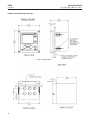
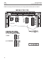
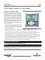
Instruction Sheet
LIQ_MAN_ABR_1066-CT-HT-FF-FI
1066
July 2013
1066 Liquid Analytical Transmitter
ESSENTIAL INSTRUCTIONS
Read this page before proceeding!
Emerson designs, manufactures, and tests its Rosemount
Analytical products to meet many national and international
standards. Because these instruments are sophisticated
technical products, you must properly install, use, and maintain them to ensure they continue to operate within their
normal specifications. The following instructions must be
adhered to and integrated into your safety program when
installing, using, and maintaining Rosemount Analytical
products. Failure to follow the proper instructions may cause
any one of the following situations to occur: Loss of life; personal injury; property damage; damage to this instrument;
and warranty invalidation.
• Read all instructions prior to installing, operating, and
servicing the product. If this Instruction Manual is not
the correct manual, telephone 1-800-854-8257 and the
requested manual will be provided. Save this Instruction
Manual for future reference.
• If you do not understand any of the instructions, contact your Emerson representative for clarification.
• Follow all warnings, cautions, and instructions marked on and supplied with the product.
• Inform and educate your personnel in the proper installation, operation, and maintenance of the product.
• Install your equipment as specified in the Installation Instructions of the appropriate Instruction Manual and per
applicable local and national codes. Connect all products to the proper electrical and pressure sources.
• To ensure proper performance, use qualified personnel to install, operate, update, program, and maintain the product.
• When replacement parts are required, ensure that qualified people use replacement parts specified by Rosemount.
Unauthorized parts and procedures can affect the product’s performance and place the safe operation of your
process at risk. Look alike substitutions may result in fire, electrical hazards, or improper operation.
• Ensure that all equipment doors are closed and protective covers are in place, except when maintenance is being
performed by qualified persons, to prevent electrical shock and personal injury.
WARNING: EXPLOSION HAZARD
DO NOT OPEN WHILE CIRCUIT IS LIVE. ONLY CLEAN WITH DAMP CLOTH.
NOTICE
If a Model 475 Universal HART® Communicator is used with these transmitters, the software within the Model 475 may
require modification. If a software modification is required, please contact your local Emerson Process Management Service
Group or National Response Center at 1-800-654-7768.
1066
July 2013
Instruction Sheet
LIQ_MAN_ABR_1066-CT-HT-FF-FI
QUICK START GUIDE – 1066 Liquid Analytical Transmitter
1. For mechanical installation instructions, see page 8 for panel mounting and page 9 for pipe or wall mounting.
2. Wire the sensor to the main circuit board. See page 10 for wiring instructions. Refer to the sensor instruction
sheet for additional details. Make loop power connections.
3. Once connections are secured and verified, apply DC loop power to the transmitter.
4. When the transmitter is powered up for the first time, Quick Start screens appear. Quick Start operating tips are
as follows:
a. A highlighted field shows the position of the cursor.
b. To move the cursor left or right, use the keys to the left or right of the ENTER key. To scroll up or down or to
increase or decrease the value of a digit use the keys above and below the ENTER key. Use the left or right keys
to move the decimal point.
c. Press ENTER to store a setting. Press EXIT to leave without storing changes. Pressing EXIT during Quick Start
returns the display to the initial start-up screen (select language).
5. Choose the desired language and press ENTER.
6. Choose measurement and press ENTER.
a. For pH or ORP, choose preamplifier location. Select Analyzer to use the integral preamplifier in the transmitter;
select Sensor/J-Box if your sensor is SMART or has an integral preamplifier or if you are using a remote preamplifier located in a junction box.
5. If applicable, choose units of measurement.
6. For contacting and toroidal conductivity, choose the sensors type and enter the numeric cell constant using the keys.
7. Choose temperature units: °C or °F.
8. After the last step, the main display appears. The outputs are assigned to default values.
9. To change output settings, to scale the 4-20mA current outputs, to change measurement-related settings from
the default values, and to enable pH diagnostics, press MENU. Select Program and follow the prompts. Refer to
the appropriate menu.
10. To return the transmitter to the factory default settings, choose Program under the main menu, and then scroll to
Reset.
11. Please call the Rosemount Analytical Customer Support Center at 1-800-854-8257 if you need further support.
2
Instruction Sheet
1066
LIQ_MAN_ABR_1066-CT-HT-FF-FI
July 2013
Specifications
GENERAL SPECIFICATIONS
Case: Polycarbonate. IP66 (CSA, FM), NEMA 4X (CSA)
Dimensions: Overall 155 x 155 x 131mm (6.10 x 6.10 x 5.15 in.). Cutout: 1/2 DIN 139mm x 139mm (5.45 x 5.45 in.)
Conduit openings: Six. Accepts PG13.5 or 1/2 in. conduit fittings
Display: Monochromatic graphic liquid crystal display. No backlight. 128 x 96 pixel display resolution. Active display
area: 58 x 78mm (2.3 x 3.0 in.). All fields of the main instrument display can be customized to meet user requirements.
Ambient temperature and humidity: -20 to 65°C (-4 to 149°F), RH 5 to 95% (non-condensing).
Storage Temperature: -20 to 70°C (-4 to 158°F)
HART® Communications: PV, SV, TV, and 4V assignable to measurement, temperature and all live HART diagnostics.
RFI/EMI: EN-61326
Complies with the following Standards:
CSA: C22.2 No 0 – 10; C22.2 No 0.4 – 04; C22.2 No. 25-M1966: , C22.2 No. 94-M91: , C22.2 No.142-M1987: , C22.2
No. 157-M1992: , C22.2 No. 213-M1987: , C22.2 No. 60529:05. UL: 50; 508; 913; 1203. ANSI/ISA: 12.12.02-2011.
ATEX: IEC 60079-0:2011, 60079-11:2011
IECEx: IEC 60079-0: 2011 Edition: 6.0, I EC 60079-11 : 2011-06 Edition: 6.0
FM: 3600: 2011, 3610: 2010, 3611: 2004, 3810: 2005, IEC 60529:2004, ANSI/ISA 60079-0: 2009, ANSI/ISA 60079-11: 2009
Hazardous Location Approvals
Intrinsic Safety (with appropriate safety barrier):
Class I, II, III, Div. 1
Groups A-G
T4 Tamb = -20°C to 65°C
ATEX
1180 II 1 G
Baseefa04ATEX0195X
EEx ia IIC
T4 Tamb = -20°C to 65°C
IECEx BAS 11.90098X
EEx ia IIC
T4 Tamb = -20°C to 65°C
Class I, II & III, Division 1, Groups A-G T4
Tamb = -20°C to 40°C for -FI option
Tamb = -20°C to 65°C for -HT and -FF options
Class I, Zone 0, AEx ia IIC T4
Tamb = -20°C to 40°C for -FI option
Tamb = -20°C to 65°C for -HT and -FF options
Non-Incendive:
Class I, Div. 2, Groups A-D
Dust Ignition Proof
Class II & III, Div. 1, Groups E-G
NEMA 4/4X, IP66 Enclosure
T4 Tamb = -20°C to 65°C
Class I, Division 2 Groups A-D
Dust Ignition proof
Class II & III, Division 1, Groups E-G
IP66 enclosure
Tamb = -20°C to 40°C for -FI option
Tamb = -20°C to 65°C for -HT and –FF options
3
1066
Instruction Sheet
July 2013
LIQ_MAN_ABR_1066-CT-HT-FF-FI
Input: One isolated sensor input. Measurement choices of
pH/ORP, resistivity/conductivity/TDS, % concentration,
total and free chlorine, monochloramine, dissolved oxygen, dissolved ozone, and temperature. For contacting
conductivity measurements, temperature element can be
a PT1000 RTD or a PT100 RTD. Other measurements
(except ORP) and use PT100 or PT1000 RTDs or a 22k NTC
(D.O. only).
Power & Load Requirements: Supply voltage at the
transmitter terminals should be at least 12.7Vdc. Power
supply voltage should cover the voltage drop on the cable
plus the external load resistor required for HART communications (250 Ω minimum). Minimum power supply voltage is 12.7Vdc. Maximum power supply voltage is 42.4
Vdc (30 Vdc for intrinsically safe operation). The graph
shows the supply voltage required to maintain 12 Vdc
(upper line) and 30 Vdc (lower line) at the transmitter terminals when the current is 22 mA.
Analog Outputs: Two-wire loop powered (Output 1
only). Two 4-20 mA electrically isolated current outputs
(Output 2 must be externally powered). Superimposed
HART digital signal on Output 1. Fully scalable over the
operating range of the sensor.
Weight/Shipping Weight: 2 lbs/3 lbs (1 kg/1.5 kg)
1500
1364
ohms
1250
Load, ohms
1000
750
545
ohms
with HART
communication
500
250
without HART
communication
0
12
18
24
30
36
42
Power supply voltage, Vdc
HART option
FIGURE 1. Load/Power Supply Requirements
4
FIGURE 2. Power Supply-Current Loop Wiring
Instruction Sheet
1066
LIQ_MAN_ABR_1066-CT-HT-FF-FI
July 2013
Specifications CONTINUED
CONTACTING CONDUCTIVITY
Performance Specifications
Measurement Range: see table below
Input filter: time constant 1 - 999 sec, default 2 sec.
Response time: 3 seconds to 95% of final reading using
the default input filter
Recommended Sensors for Conductivity
All Rosemount Analytical ENDURANCE Model 400 series
conductivity sensors (Pt 1000 RTD) and Model 410VP 4electrode sensor.
PERFORMANCE SPECIFICATIONS
Recommended Range – Contacting Conductivity
Cell
0.01S/cm
Constant
0.01
0.1mS/cm
1.0mS/cm
10mS/cm
100mS/cm
0.01mS/cm to 200mS/cm
0.1
10mS/cm
100mS/cm
1000mS/cm
200mS/cm to 2000mS/cm
0.1mS/cm to 2000mS/cm
1.0
1000mS/cm
1 mS/cm to 20mS/cm
4-electrode
2000mS/cm to 20mS/cm
20mS/cm to 200mS/cm
2mS/cm to 1400mS/cm
Linearity for Standard Cable ≤ 50 ft (15 m)
±0.6% of reading in recommended range
±2% of reading outside high recommended range
±5% of reading outside low recommended range
±4% of reading in recommended range
Temperature specifications:
Temperature range
0 to 200°C
Temperature Accuracy,
Pt-1000, 0-50°C
± 0.1°C
Temperature Accuracy,
Pt-1000, Temp. > 50°C
± 0.5°C
5
1066
Instruction Sheet
July 2013
LIQ_MAN_ABR_1066-CT-HT-FF-FI
Specifications CONTINUED
TOROIDAL CONDUCTIVITY
Performance Specifications
Measurement Range: see table below
Input filter: time constant 1 - 999 sec, default 2 sec.
Response time: 3 seconds to 95% of final reading
Recommended Sensors for Conductivity
All Rosemount Analytical submersion/immersion and
flow-through toroidal sensors.
PERFORMANCE SPECIFICATIONS
Recommended Range - Toroidal Conductivity
Model
1mS/cm
226
10mS/cm
100mS/cm
1000mS/cm
10mS/cm
100mS/cm
5mS/cm to 500mS/cm
1000mS/cm
2000mS/cm
500mS/cm to 2000mS/cm
225 & 228
15mS/cm to 1500mS/cm
242
1500mS/cm to 2000mS/cm
100mS/cm to 2000mS/cm
222
(1in & 2in)
500mS/cm to 2000mS/cm
LOOP PERFORMANCE (Following Calibration)
Model 226: ±1% of reading ±5mS/cm in recommended range
Models 225 & 228: ±1% of reading ±15mS/cm in recommended range
Models 222, 242: ±4% of reading ±5mS/cm in recommended range
Models 225, 226 & 228: ±5% of reading outside high recommended range
Temperature specifications:
Temperature range
-25 to 210°C (-13 to 410ºF)
Temperature Accuracy,
Pt-100, -25 to 50 °C
± 0.5°C
Temperature Accuracy,
Pt-100,. 50 to 210°C
± 1°C
6
Instruction Sheet
LIQ_MAN_ABR_1066-CT-HT-FF-FI
1066
July 2013
Installation
UNPACKING AND INSPECTION
Inspect the shipping container. If it is damaged, contact the shipper immediately for instructions. Save the box. If there
is no apparent damage, unpack the container. Be sure all items shown on the packing list are present. If items are missing, notify Rosemount Analytical immediately.
INSTALLATION
General Information
1. Although the transmitter is suitable for outdoor use, installation is direct sunlight or in areas of extreme temperatures is not recommended unless a sunshield is used.
2. Install the transmitter in an area where vibration and electromagnetic and radio frequency interference are minimized or absent.
3. Keep the transmitter and sensor wiring at least one foot from high voltage conductors. Be sure there is easy access
to the transmitter.
4. The transmitter is suitable for panel, pipe, or surface mounting.
5. The transmitter case has six 1/2-inch (PG13.5) conduit openings. Use separate conduit openings for the power/output cable, the sensor cable, and the other the sensor cable as needed (pH input for free chlorine with continuous pH
correction).
6. Use weathertight cable glands to keep moisture out to the transmitter. If conduit is used, plug and seal the connections at the transmitter housing to prevent moisture from getting inside the instrument.
PREPARING CONDUIT OPENINGS
There are six conduit openings in all configurations of Model 1066. (Note: four enclosure opening plugs will be provided upon shipment.)
Conduit openings accept 1/2-inch conduit fittings or PG13.5 cable glands. To keep the case watertight, block unused
openings with NEMA 4X or IP66 conduit plugs.
NOTE: Use watertight fittings and hubs that comply with your requirements. Connect the conduit hub to the
conduit before attaching the fitting to the transmitter.
WARNING: RISK OF ELECTRICAL SHOCK
Electrical installation must be in accordance with the National Electrical Code (ANSI/NFPA-70) and/or any other applicable
national or local codes.
ELECTROSTATIC IGNITION HAZARD
Special condition for safe use (when installed in hazardous area)
1. The plastic enclosure, excepting the front panel, must only be cleaned with a damp cloth. The surface resistivity of
the non-metallic enclosure materials is greater than one gigaohm. Care must be taken to avoid electrostatic charge
build-up. The Model 1066 Transmitter must not be rubbed or cleaned with solvents or a dry cloth.
2. The panel mount gasket has not been tested for type of protection IP66 or Class II and III. Type of protection IP66
and Class II, III refer the enclosure only.
3. The surface resistivity of the non-metallic enclosure materials is greater than one gigaohm. Care must be taken to
avoid electrostatic charge build-up. The Model 1066 Transmitter must not be rubbed or cleaned with solvents or a
dry cloth.
4. Special Condition of Use of 1066-C-FF/FI-67 and 1066-T-FF/FI-67. For use with simple apparatus model series 140,
141, 142, 150, 400, 401, 402, 402VP, 403, 403VP, 404, and 410VP contacting conductivity sensors and model
series 222, 225, 226, 228 toroidal sensors.
7
1066
July 2013
FIGURE 3. Panel Mounting Dimensions
8
Instruction Sheet
LIQ_MAN_ABR_1066-CT-HT-FF-FI
Instruction Sheet
LIQ_MAN_ABR_1066-CT-HT-FF-FI
1066
July 2013
FIGURE 4. Pipe and wall mounting dimensions (Mounting bracket PN: 23820-00)
9
1066
July 2013
Instruction Sheet
LIQ_MAN_ABR_1066-CT-HT-FF-FI
FIGURE 5. Contacting and Toroidal Conductivity sensor wiring to 1066 circuit board (1066-C and 1066-T)
10
Instruction Sheet
1066
LIQ_MAN_ABR_1066-CT-HT-FF-FI
July 2013
SCHEMATIC, INSTALLATION
MODEL 1066 XMTR, (CSA)
FIGURE 6. CSA Installation
11
1066
July 2013
Instruction Sheet
LIQ_MAN_ABR_1066-CT-HT-FF-FI
SCHEMATIC, INSTALLATION
MODEL 1066 XMTR, (CSA)
FIGURE 7. CSA Installation
12
Instruction Sheet
1066
LIQ_MAN_ABR_1066-CT-HT-FF-FI
July 2013
SCHEMATIC, INSTALLATION
MODEL 1066 XMTR, (CSA)
FIGURE 8. CSA Installation
13
1066
July 2013
Instruction Sheet
LIQ_MAN_ABR_1066-CT-HT-FF-FI
LABEL, INFO, 1066
CSA
FIGURE 9. CSA Label Information
14
Instruction Sheet
1066
LIQ_MAN_ABR_1066-CT-HT-FF-FI
July 2013
9241717-00
LABEL, INFO, 1066
ATEX
FIGURE 10. ATEX, IECEx Label Information
15
1066
July 2013
Instruction Sheet
LIQ_MAN_ABR_1066-CT-HT-FF-FI
SCHEMATIC, INSTALLATION
MODEL 1066 XMTR, (FM)
FIGURE 11. FM installation
16
Instruction Sheet
1066
LIQ_MAN_ABR_1066-CT-HT-FF-FI
July 2013
SCHEMATIC, INSTALLATION
MODEL 1066 XMTR, (FM)
FIGURE 12. FM Installation
17
1066
July 2013
Instruction Sheet
LIQ_MAN_ABR_1066-CT-HT-FF-FI
SCHEMATIC, INSTALLATION
MODEL 1066 XMTR, (FM)
FIGURE 13. FM installation
18
Instruction Sheet
1066
LIQ_MAN_ABR_1066-CT-HT-FF-FI
July 2013
LABEL, INFO, 1066
FM
FIGURE 14. FM label information
19
1066
Instruction Sheet
July 2013
LIQ_MAN_ABR_1066-CT-HT-FF-FI
facebook.com/EmersonRosemountAnalytical
8
AnalyticExpert.com
Credit Cards for U.S. Purchases Only.
twitter.com/RAIhome
youtube.com/user/RosemountAnalytical
Emerson Process Management
©2013 Rosemount Analytical, Inc. All rights reserved.
2400 Barranca Parkway
Irvine, CA 92606 USA
Tel: (949) 757-8500
Fax: (949) 474-7250
The Emerson logo is a trademark and service mark of Emerson Electric Co. Brand name is a mark
of one of the Emerson Process Management family of companies. All other marks are the property
of their respective owners.
rosemountanalytical.com
© Rosemount Analytical Inc. 2013
Rev. A
The contents of this publication are presented for information purposes only, and while effort has
been made to ensure their accuracy, they are not to be construed as warranties or guarantees,
express or implied, regarding the products or services described herein or their use or applicability.
All sales are governed by our terms and conditions, which are available on request. We reserve the
right to modify or improve the designs or specifications of our products at any time without notice.