1
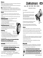
Maintenance
English
Elinchrom flash units are designed for years of professional use, and require very little maintenance
other than changing the modelling lamp from time to time.
When the lamp requires replacement, the unit should be disconnected from the mains supply, the
lamp carefully unscrewed and a new lamp fitted.
Note : The modelling lamp is a 196V, 100W lamp which is overrun to give a higher colour
temperature and light output equivalent to a 150W lamp. Although this has the same screw fitting
as some domestic light bulbs, its dimensions are different and only this type of lamp should be used.
Use of other types of lamp may break the flashtube and invalidate the warranty.
Safety note
The flash tube is sensitive to some of the natural oils in the skin, and should not be touched.
The unit should be kept clean using a dry duster, paying particular attention to the reflectors and
controls.
To protect the finish of the unit, and for electrical safety reasons, the unit should not be cleaned
with fluids or solvents.
Flashtube Removal procedure (only for plug-in : Elinchrom 250C and 500C)
1. turn on the flashunit and disconnect from power source.
2. Allow flash unit to remain undisturbed for a minimum of 10 minutes to permit
the capacitor to discharge completely.
3. Unscrew and remove modelling lamp.
5. Firmly grasp the flashtube around the edges and pull straight out.
Flashtube Replacement procedure (only for plug-in)
1. Carefully align the flashtube terminals with the sockets in the flash head.
2. gently push flashtube straight into the sockets, until it is firmly seated.
3. Ensure that the retainer clip is engaged at the bottom of the flashtube.
4. replace the modelling lamp.
Troubleshooting
IF THE UNIT DOES NOT FUNCTION
1. The mains switch (3) is ON, but not illuminated.
Switch off the unit and change the mains fuse (2).
Units 250 - 500 -1000 - 750 S -1500 S
Instructions for Use
Dear Photographer,
Thank you for buying your Elinchrom compact flash
unit.
All Elinchrom products are manufactured using the
highest quality materials under strict supervision to
ensure complete satisfaction.
Please follow the instructions given below to obtain
the best possible results from your Elinchrom flash unit.
All Elinchrom flash units are manufactured for the studio
and location use of professional photographers.
All Elinchrom units have a bayonet mount and locking ring
reflector fitting, for fixing all Elinchrom and Prolinca accessories.
Identification
label
Safety note :
According to safety regulations, we draw your attention to the fact that these
electronic flash units are not designed for use outdoors, in damp or dusty conditions,
Plug-in
flash tube
(white insulation)
Use only time-lag fuse, corresponding to the Elinchrom model (see identification label).
2. The on/off switch (3) is lit, the green indicator (5) is lit but the unit does not function.
The cause of this problem: could be an electronic component failure, or the
flash tube may be faulty.
The equipment is not user serviceable and contains dangerous by high voltages.
Please return the unit to an authorized Elinchrom service.
3. The ON/OFF switch (3) is lit but the open flash ready/light (7) is not illuminated.
In this case there is an internal problem. The cause may be a component failure.
and should not be used after being exposed to sudden temperature changes
causing condensation. They must always be connected to an earthed (grounded)
mains supply.
On no account should any objet be inserted into the ventilation holes. The flash tube
and modelling lamp generate heat, and they should be kept clear of combustible
materials both during and after use.
The units may retain an internal charge for a considerable time even though
disconnected from the power supply.
Other accessories
Before you start !
Now you have chosen Elinchrom for your flash unit, why not expand your studio equipment by
selecting one of the useful range of accessories from the Elinchrom range.
The units are factory-set for operation on 220-240V/50-60Hz or (110/130V/50-60Hz).
Before connecting for the first time, check to make sure that your power supply
coincides with the voltage given on identification label.
FOR YOUR SAFETY, NEVER OPEN YOUR COMPACT FLASH.
DO NOT ATTEMPT TO REPAIR THE UNIT YOURSELF
YOURSELF..
PLEASE SEND THE UNIT TO YOUR ELINCHROM AGENT
P.S : If you are abroad, please contact Elinca S.A. Switzerland.
Tel. + 41 021 637 26 77 - Fax + 41 021 637 26 81 - E-mail : [email protected]
and ask for address, phone, fax number and E-mail of the nearest Elinchrom agent.
Web : www.elinchrom.com
Elinca sa
M.E. compacts .EL. 9.01 Engl. (73226) Printed in Switzerland
FLASH SYSTEMS STORE ELECTRICAL ENERGY IN CAPACITORS BY APPLYING
!
HIGH VOLTAGE. FOR YOUR SAFETY, NEVER OPEN OR DISASSEMBLE YOUR FLASHES.
ONLY AN AUTHORISED SERVICE ENGINEER SHOULD OPEN OR ATTEMPT TO REPAIR
THE UNITS. FOR REPAIRS, BRING THEM TO YOUR ELINCA/ELINCHROM AGENT.
ELINCA S.A. Renens/Switzerland
Controls
1. Mains inlet socket with spare fuse
2. Mains fuse (slow blow)
3. Illuminated mains on/off switch
4. Modelling lamp switch
5. Open flash «Test» and ready
6. Slave cell on/off
7. Stepless sliding flash variator
8. Stepless modelling lamp control
9. Synchro-socket
10.Umbrella tube
5
Synchronisation
4
7
3
2
6
Setting Up
Your flash unit should only be used while mounted to a light
1
8
9
stand or some similar secure support.
The unit will fit onto any 5/8th inch spigot and is held at the
required angle by tightening the clamping handie. The front
end of the head has a bayonet fitting and locking ring
which holds the protective cap in place and allows
reflectors and other accessories to be fitted during use.
DO NOT operate the unit without first removing the black
protective cover. To remove the protective cap, rotate the
locking ring, so that the white dot, on the ring, lines up with
that on the bayonet. This un-locks the bayonet and allows
the protective cap to be removed by twisting anticlockwise.
Fitting the reflector is the reverse of this operation. When
fitted to the unit, all attachments should be locked in place
Locking Ring
by turning the locking ring so that the two white dots are
Modelling
about 2 cm apart.
lamp
Operating instructions
The mains cable is connected to the mains inlet (1)
on the control panel.
The fuse holder (2) contains a mains fuse (together
with a spare fuse).
The unit may now be switched on using the mains
on-off switch (3). This will illuminate showing that
power is present.
Flash power
As soon as the power unit is switched on, it charges to the set power and the green
'ready' lamp (5) lights to show that the unit is charged and ready to fire.
The power level is controlled by the flash variator (7). This is continuously variable of
3 f-stop, from the full power to 1/4th.
When reducing power, a manual flash should be fired by pressing the open flash
button (5). This dumps the extra power and allows the unit to recycle to the lower level
selected. When the modelling lamp is switched on, the power level is controlled by the
power control (8). This is continuously variable on 3 f-stop, from the full to 1/4th.
*The EL 750 and EL 1500S, provides continuously variable adjustment of 5 f-stop, from the full
power to 1/16th. This units have an integrated discharge system. In order to restrict the heating of
the unit, we suggest to release a flash with the green test button (5), after each strong reduction
of power (more the 2f-stop).
This allows to release the excess of energy in the flash tube, you will gain time and extend the life
span of your compact units.
Umbrellas
Modelling lamp
The lamp is switched on using the modelling lamp
switch (4). The Krypton E27 modelling lamp is specially
designed for the Elinchrom units.
Note : the other lamps may touch the flash tube and
either may break.
There are some alternatives available and your
authorized Elinchrom dealer can advise which can
be used.
*The EL 750S - 1000 - 1500S are fitted with a 200W
halogen lamp. It is vital that the correct fuse (2 amp
flink) is fitted in the modelling lamp fuse holder when
this lamp is being used.
The flash may be triggered in a number of ways.
Manual flashes may be triggered by using the green open flash switch ( 5 ) which
incorporates the ready lamp, for testing, metering, etc.
Synchronisation with the camera is achieved by using a synch cable, which connects
the flash synch socket (9) to the standard flash connector on the camera or direct to
the hot shoe using an adapter.
If more than one unit is in use, additional units may be synchronised to the first using
the built-in photocell (6). This is switchable, and operates when the transparent
square button is raised. The remote photocell of the unit picks the flash from the main
unit and fires the unit at the same instant, avoiding the need for synch cable linking
all the units.
For more demanding applications, a variety of accessories is available such as
extension synch cables, remote photocells and radio release links.
An indicator lamp above the photocell indicates whether it is switched on (green) or
off (red).
Flash tube
Umbrella tube (10)
(entry point)
Tilthead with locking
umbrella holder
An umbrella with a 7 mm shaft may be used with the unit, by opening the umbrella
and inserting the end of the shaft into the umbrella tube (10) while holding the unit with
the other hand.
The tube contains a spring which holds the umbrella firmly in place. The correct position
of the umbrella must be adjusted so that the position of the light from the reflector
coincides with the edge of the umbrella.
NOTE : the diameter of the umbrella socket is designed to suit Elinchrom or Prolinca
umbrellas only and the use of other shaft sizes may cause damage to the unit.
An alternative umbrella clamp is attached to the tilt clamp handle which accepts
umbrellas of other manufacturers.
The umbrella is removed by grasping the shaft firmly and withdrawing it from the
umbrella tube while holding the unit with the other hand. Care should be taken to
avoid striking the flashtube with the end of the shaft on removal.
When the unit is used with some larger lightshapers, the unit fits inside the lightshaper
which itself is supported on a stand. In this case, the unit is fixed into the mountig ring by
using the handle to rotate (clockwise) the unit in place. Once again it is important to
secure the flash using the locking ring.