1
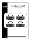
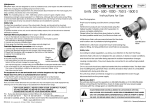
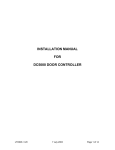
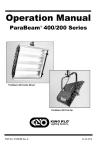
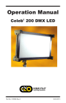
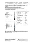
Parabeam 600-S User Manual 1.0 Getting Started 1.1 1.2 1.3 1.4 Hardware supplied Tools required for installation Functional Description Applications 2.0 Things to consider 2.1 2.2 2.3 2.4 2.5 2.6 2.7 Solar panels Affects of sunlight Transmission range Height above ground Uneven ground Maximum beam distance Hardware and Wiring notes 3.0 Installation procedures 3.1 3.2 3.3 Mounting the items Cable preparation Alignment and testing 4.0 Base receiver instructions 4.1 4.2 4.3 4.4 4.5 4.6 4.7 4.8 4.9 Locating your base receiver Adjusting Volume Isolating zones Un-Isolating zones Timed output on-times Timed output termination Learn mode (adding beamsets) Clearing zone positions Cascading master and slave receivers 5.0 Maintenance and troubleshooting 5.1 5.2 5.3 5.4 Resolving detection issues Resolving false activation issues If red light shows on main transmitter Reception issues 6.0 Warranty Information 6.1 6.2 Disclaimer Limitations 7.0 Diagrams 2 1.0 Getting Started 1.1 Hardware supplied 1X 1X 2X 1X 1X 1X 2X 2X 2X 1X 10 X 10 X 6X Main transmitter unit (With antenna) Infra-red emitter unit (IR emitter) Battery packs (inside each Parabeam unit) RX-1 Base receiver Rod antenna for base receiver 12 Volt DC power pack (for base receiver) Solar panel / cable assemblies Smaller Aluminium brackets Larger Aluminium brackets Pack of plastic cable clips (approximately 20) Stainless machine screws Stainless nuts 30mm Tech screws 1.2 Tools required for installation • • • • • • • • Battery drill / bits 2.5mm wide flat bladed screwdriver 6.0mm wide flat bladed screwdriver Side cutters or wire strippers 8.0mm socket /driver (for “Tech” screws) Hammer Box cutter / Craft knife Pliers 1.3 Functional Description The 600-S forms an invisible point-to-point beam, up to 50m wide, between Infrared emitter unit and the main transmitter. Alignment between the two parts is easily achieved by “empirical techniques” (a series of simple tests) At greater beam distances more careful alignment is needed to ensure high false alarm immunity. When a solid object blocks the beams path, the radio transmitter sends out a two-second transmission. The transmission contains a unique ID code and your base receiver will receive this transmission if it is within range (See section 3.3) and alert you accordingly with a beeping sequence. During this transmission a green LED will illuminate on the face of the main transmitter unit. Pulse integration, is another technology used to minimize false activations from rain and transient disturbances. The outgoing beam is pulsed rapidly. For a valid activation to occur, approximately 20 of the incoming light pulses must be missing sequentially. This can’t occur unless the beam is interrupted continuously for approximately 250ms. (0.25 seconds) Our detection technology cannot be compared with the inferior “single ended” PIR based systems. This is because PIR systems are triggered by a warm body moving within their field, and because of this, false alarms are common and performance not consistent. 1.4 Applications • • • • • • • • • • Driveway alert systems for farms, orchards and residential properties Customer alert for home based businesses, timber yards Beach properties and properties vulnerable to public access Fuel storage facilities After-hours security for car sales yards Visual alert for noisy environments Portable installations on construction sites (using GSM based models) After-hours monitoring of large outdoor venues Generating an event in “event driven CCTV” applications A photoelectric beam for solar-powered automatic gates 3 2.0 Things to consider Installation is extremely simple, only two solar panels and the main Parabeam units need mounting. Please read these instructions carefully to prevent damage and ensure reliable operation. 2.1 Solar Panels Take care handling and mounting the solar panels. Do not mount them where they could be damaged later. The solar panels can be mounted flat - toward the sky. They can be mounted slightly below eye level of a post or fence paling so as to be difficult to see from an incoming direction. They must not be shaded for extended periods of the day. 2.2 Affects of sunlight Low angle sunlight should never directly be in line with the main transmitter unit as it may cause false activations (The direct line of optical acceptance). The IR emitter part is not affected by sunlight at all. Immunity to low angle, direct sunlight reduces as the beam length increases, so more care is required in these situations and the beams path may need to be different from your obvious first choice. If the main transmitter is shaded at times of low angle sunlight there will be no problem. This applies to any “photoelectric” beam - sunlight is intense compared to the strength of light from the infrared emitter. 2.3 Transmission range Transmission range is entirely dependant on obstacles modifying the radio signals path before it reaches the receiver, so no precise figures are possible. During rural trials, ranges of 200-700 Meters were experienced. Try not to test the Parabeam to the limits of its transmission range, as you cannot guarantee it will always communicate. Range boosting antennas are available for challenging situations. Metal surfaces very close to the transmitting antenna such as a tin fence or shed may tend to reflect the signal more in one direction and should be avoided if you require maximum range. Wire fences having a small mesh size may cause a similar effect if too close. If radio distance is great it could be advantageous to mount the main transmitter unit on the side of the driveway nearest your house so larger vehicles do not block the radio transmission. For shorter ranges you need pay less attention to these considerations. 2.4 Height above ground The beam should be around 800mm above ground or higher to allow animals such as sheep or dogs to pass freely underneath. If a vehicle can be traveling at speed through the beam, a height lower than the cars windows is preferred, otherwise the beam may pass through the windows as the vehicle passes and any interruption of the beam may not be of long enough duration to cause activation. 2.5 Uneven ground Irregular ground level between one end of the beam and the other may introduce two possible situations. One is that the beams effective height above ground may be low in places and high in others, creating potential points where someone can walk under the beam without being detected and others where small animals may cause unwanted activations. If the ground is very uneven, either a compromise on beam height must be met, multiple beams used or a better location chosen. Another situation may arise is where sloping ground means direct beam alignment on the horizontal azimuth is not possible without it seeming that tilting the units is needed. The Parabeams Lightshaper optics will compensate for this providing the ground slope is no greater than 10 degrees. So keep both Parabeam units mounted level. Using a length of string between the two proposed mounting points is an ideal way of determining the exact trajectory of the detection beam before mounting. 4 2.6 Maximum beam distance With regard to the maximum length of the protection beam, try and keep this within 50 Meters to minimize the chances of false triggers from extremes of weather and other environmental factors. Beam distances should be far less if there is absolutely no way of avoiding strong, low angle sunlight. 2.7 Hardware and Wiring notes 1. The front cover for the main transmitter has a special lens bonded on its inner surface so place this where it will not be damaged during installation. When refitting, take care because the LED (light) on the circuit board must enter its small hole on the inside cover. 2. The front covers on the two Parabeam units are not interchangeable, do not get them mixed up! 3. Never install system in the rain or poor lighting. 4. Never over tighten the plastic cover screws and use a screwdriver of correct blade width. 5. Do not seal front covers with silicon, they have an IP66 rated gasket and it will be impossible to remove the covers in future without damage. 6. Use the aluminium brackets and stainless screws supplied for mounting the main units for the following reasons: – You will need to swivel the main brackets on the smaller ones when aligning – The metal plays a major role in radio transmission efficiency – Screwing enclosures directly to an uneven surface risks twisting the enclosures and damaging the internal components 7. Never drill holes the enclosures or put screws in any place other than the corner mounting holes. 8. Never paint the transmitting antenna (you can paint the enclosure part) 3.0 Installation procedures 3.1 Mounting the units Now that you have read these notes, choose two suitable mounting points for the hardware and fix the small aluminium arm into position. Remove the front cover from the IR emitter enclosure first using a larger flat bladed screwdriver and insert four stainless screws into the corner mounting holes. Fasten to the larger bracket, and mount the assembly so it swivels off the smaller arm already mounted. Now mount the solar panel making sure there is no tension on the cable junction. Using the plastic clips provided, run the solar panels cable in a tidy fashion to the IR emitter / transmitter. 3.2 Cable preparation Two connections need to be made inside each enclosure. Make sure when cutting the cable you allow enough length for the wires to reach the circuit boards, and you can freely swivel the assembly. Prepare the wires carefully using the method described below and compare with diagram. 1. Use a craft knife to make a shallow cut around the outer PVC insulation 80mm from the end. Bend the cable back and forwards at that point and remove the outer sheath. 2. Strip the ends of each wire to expose no more than 6mm of the copper wire itself. Carefully push wires through the underside of the enclosure via the cable gland and guide them forward, under the battery pack to the front of the circuit board. (The outer PVC sheath should only just enter the inside of the enclosure) 3. Twist the bare copper wires to tidy the individual strands, then insert into the BROWN and BLUE terminals accordingly. Tighten with the correct screwdriver then gently pull on each wire to make sure it is adequately clamped. 5 4. Gently tighten the black cable gland. 5. Arrange the wires so they will not interfere with the optical assemblies. 6. Plug the battery packs female connector onto the male ‘header’ on the circuit board to apply power, make sure the battery pack is seated flat on the ledges within the enclosure 7. Screw front cover back on the enclosure. Tighten two diagonally opposed screws first, then the other two. Now do the same with the main transmitter unit, observing the same procedure. Finish this stage by visually aligning the two main units as best you can. If it is difficult to get a good line of site by looking from behind each unit, you may find it easier to run a length of string between the two units as an aid. 3.3 Alignment and testing At this stage you are now ready to fine-tune the beams alignment. If closely aligned already you will notice a green light illuminate for 2 seconds every time the beam is broken. If you move your hand through the beam fast, there will be no response, this is normal and a feature helping to make it immune to transient disturbances. For the fine alignment procedure, make sure no part of your body interferes with the beam. Start with the main transmitter and, using a square piece of cardboard (not paper) gradually block off the rectangular window on the front face of the unit moving in from the right side first. The instant you see the green light come on, take note of the section of window not yet blocked. Ideally this should be in the order of 1-5mm wide depending on the distance between the beams. Carry out the same test from the window’s left side, moving right this time and notice when the green light illuminates. Optimum alignment is found when the unblocked section of window is the same size regardless of which direction the test is done from, so you may need to adjust the assembly on its mounting arm until you achieve this result. Once the IR emitter end is aligned as well, the strength of the beam will be even greater, meaning the trigger point will occur when an even smaller section of unblocked window remains. Depending on the beam distance you may need someone to help you if you cant see the green LED very easily. Pocket receivers are helpful during this procedure. 4.0 Base Receiver instructions 4.1 Locating your base receiver Choose a location for the receiver in your house away from cordless phones, plasma TV’s and computers. Plug the base receiver’s power pack into the wall socket and either of the the two round DC jacks on the rear or front of the receiver. Check that the blue power LED is illuminated. Attach the antenna to terminal (The far right terminal if looking from the rear of the receiver) and always keep the antenna rod vertical. Use the correct screwdriver and don’t over-tighten. Now carry out a final test of your system by having someone go and walk through the beam, you will hear one long beep followed by a single short beep. This sequence occurs twice for each activation. 4.2 Adjusting Volume The RX-1 has a four step volume adjustment. To adjust the volume of the alert tones, press the SPKR key for two seconds, the current volume is shown using the Zone’s 1-4 LED’s as a bar graph. Use the shift (>) key to set to the desired level. The new volume level will be displayed and sounded. To store - press OK, to exit without changing previous setting, press SPKR. 4.3 Isolating Zones You can isolate temporarily any zones you don’t want to receive alerts from. If a zone is isolated, the receiver can still receive a signal from it and display the corresponding LED, however there will be no alert sound heard. 6 If you try and isolate zones when no devices have yet been learnt by the receiver, a chasing light effect will be observed and the receiver will exit this mode automatically. 1. To enter isolate zone mode press and hold the shift key > for two seconds. The power LED flashes - then all valid zone LED’s illuminate - ones that have been previously isolated are flashing. As long as the shift key remains pressed, the current status of all zones will be displayed. When > key is released the status of the lowest order zone is now shown - flashing if isolated (The lowest order zone will be zone 1 unless it has been cleared of any code) . 2. To toggle that zone between isolated and active status press the SPKR button. The > key may now be pressed to move to the next valid zone and again, SPKR is used to isolate or un-isolate that zone. 3. To exit and save your settings, press the OK button. The current settings will remain displayed as long as the OK button is held down. 4. If any zones are left isolated the power LED blinks very slowly 4.4 Un-isolating zones 1. Press the OK button for two seconds, all active zones illuminate for two seconds or as long as the key is pressed - showing their now un-isolated status 2. Power LED stops flashing - all zones are now active 4.5 Timed output on-time The receiver has a timed output you can use to control lighting etc. The output is “open collector” type which means it switches any load to ground (with respect to +12volts) when active. To control mains lighting you would need a relay with a 12 volt coil and 240volt contact rating. You can adjust the on period from 20 seconds to 120 seconds in 20 second increments. 1. Press both the OK and SPKR keys for two seconds, the current on period is now shown on the zone LED’s each LED represents 20 seconds - Six LED’s represents 120 seconds etc. 2. Use the > key to adjust the number of LED’s on. 3. Press the OK key to save the new settings and exit, or press the SPKR key to exit unchanged. 4.6 Timed output termination The timed output will turn on when a zone is triggered, it may be forced off prematurely by pressing any key briefly. 4.7 Learn Mode The RX-1 may be taught to respond to new beamsets or repeater transmitters by entering learn mode. first decide which devices are to go on particular zone positions. For example; Front gate beamset = zone 1, fuel tank beamset = zone 2 etc. 1. Press > and SPKR buttons together for two seconds - the power LED flashes - after two seconds the zone LED’s illuminate to show active zones (devices already learnt) Zone status will show as long as keys remain pressed. 2. The zone 1 LED starts to flash, at this point either activate a beamset or press the > key to advance to another zone position before activating the beamset. Any activation will overwrite a previously stored code so avoid triggering beamsets while on the incorrect zone position. 3. When new code loaded, the receiver will exit learn mode automatically, and will now respond upon receiving any signals from the newly loaded device. 7 4.8 Clearing zone positions For whatever reason you may want to permanently clear a previously loaded beamset or transmitter from a particular zone position. 1. Press > and SPKR buttons together for two seconds - the power LED flashes - after two seconds the zone LED’s illuminate to show active zones (devices already learnt) Zone status will show as long as keys remain pressed. 2. The zone 1 LED starts to flash, press the > key to advance to the zone position you want to clear. 3. Clear zone by pressing the SPKR key - Receiver will clear zone and exit automatically - to clear another zone repeat procedure. 4.9 Cascading master and slave receivers On large properties where beamsets may be long distances away from the house, (600m - 3000m etc) it is often necessary to install a MegaBeam antenna to supply the receiver with a much stronger signal than would be possible from its small rod antenna. In this situation, it is desirable to retain as much of the received signal as possible and if two base receivers are needed it is possible to connect them in series. In this configuration the master receiver gets the signal first and then sends the raw data on to the slave receiver, so there is no need to split the antenna signal itself. Thus you have two completely independent receivers that you may configure according to volume level, zones monitored or zones isolated. 5.0 Maintenance and troubleshooting A few times a year you may need to clean any dust, spider-webs or plant overgrowth from the front face of the two units and solar panels. 5.1 Resolving detection issues If the system does not seem to detect all vehicles, it could be one of two possible reasons 1. The receiver is on the borderline of its range. Shift the receiver to another location in the house or install a range-boosting antenna. Note: The antennas supplied with your equipment are cut to a precise length. Making them longer or shorter will ruin their performance. 2. The beam is passing straight though the car windows and because the vehicle is traveling fast it is not being detected. Lower the beam height 5.2 Resolving false activation issues False alarms are rare with Parabeam systems, however if you do experience this it could be one of the following: 1. Low angle sunlight entering main transmitter’s sensitive eye. Re-locate beam or try shielding the window of main transmitter from low angle sunlight. 2. Something intermittently obstructing the Infra-Red beam (Flax, Animal, etc) 3. Check beam alignment (section 3.3) 4. Low battery on IR emitter. Check solar panel is correctly wired and is not shaded. 5. Batteries no longer holding adequate charge overnight. (Estimated 3 year life) 5.3 If a red light shows on main transmitter 1. When a red light shows on the main transmitter instead of the usual green light, its battery is low. Check solar panel wiring or its location. The solar panel should be emitting approximately 10 Volts on a sunny day, 8 and around 6-9 volts on an overcast day. (Measured while solar panel is disconnected from the Parabeam unit) 2. Too many activations occurred in a short time period and the solar panel has not kept up with the charge. The system will recover by itself if it is a one-off situation. Address any problem with false activations quickly to prevent severe battery drain, or disconnect battery from main transmitter until you have time to address the problem. Please note that if severe battery drain on the main transmitter has occurred, you should return the battery pack for full charging as the solar panel may not be capable of restoring its charge. 3. Battery pack is old and is not holding a charge overnight. Order a new battery packs. Estimated lifespan 3 years. 4. A fault has occurred within the transmitter causing the battery to excessively discharge or make it appear to be discharged. Return this part for servicing. 5.4 Reception issues Reception problems have occasionally been reported after rain. The cause is usually an unusually dense hedge or bush in between the beam-set and the base receiver attenuating the radio signal when wet. If the suggestions below do not help, please call us immediately. 1. Try shifting the location of the base receiver first. It could be in a poor reception pocket within your home. 2. Consider whether moving the beam-set clear of the problem is an option. 3. Install an outdoor range-boosting antenna at the house 6.0 Warranty Information This system has a 12 Month warranty for any component defect or failure in the course of normal operation. The warranty does not cover any form of damage either accidental or willful including incorrect wiring, water damage, electrostatic damage (electric fence / lightning) or mains power surge. Should anything of this nature occur during the warranty period we subsidize the cost of replacement parts. Please call us urgently if there are any problems that you are unable to rectify with the advice included. 6.1 Disclaimer The manufacturer shall have no liability for any personal injury, bodily injury, death, property loss or damage or other loss whether direct, indirect, consequential or otherwise, based on a claim the product has failed to function. However, if the manufacturer is held liable for any such loss or losses incurred while the product is under warranty, the manufacturer’s maximum liability shall not in any case exceed the purchase price of the product, which shall be fixed as liquidated damages and not as a penalty, and shall be an exclusive and complete remedy against the manufacturer. 6.2 Limitations Parabeam systems are very reliable and are tested to high standards, however any wireless device has the potential to be affected by outside interference or environmental factors. This product is used on the understanding that its radio signals can be blocked and interfered with by other transmissions on the same frequency including simultaneous transmissions from another beam-set. 9 7.0 Diagrams RX1 Receiver Connection DiagramDiagram RX1 Receiver Connection CAUTION: WHEN INTERFACING WITH MAINS VOLTAGES, ALWAYS USE A RELAY AND HAVE A REGISTERED ELECTRICIAN CARRY OUT THIS WORK. ! CONNECTING A RELAY TO TIMED O/P 3 Rod antenna here (if no outdoor antenna) ANTENNA 8 EARTH 7 DATA OUT 6 BEEPER 5 PAGER 4 TIMED O/P FOR LIGHTS ETC 3 +12 VOLTS COMMON 2 EARTH 1 230VAC INPUT Neutral 2 Coax cable to outdoor antenna Receiver connections Remote Beeper Pager relay transmitter should be stuck to nearest window mounted vertically, or see manual for longer distance options. Mains Adaptor (keep 200mm away from aerial) 12 VOLTS DC INPUT - + Note: Switched outputs (Timed O/P, Pager, Beeper) are 12 volts when active. Total load current from one, or all three outputs combined must not exceed 450mA. RX2 / RX3 Receiver Connection Diagram (Used where an outdoor aerial feeds a system needing multi-room receivers) Coax cable to outdoor antenna Mains Adaptor 4-core alarm cable Mains Adaptor (not required for RX3 Receiver) 2 1 EARTH 3 +12 VOLTS 4 5 6 7 DATA IN 1 ROOM 1 RX1 Master Receiver 8 2 EARTH 3 +12 VOLTS 4 5 6 DATA OUT 7 Red wire - only connect if RX3 Slave Receiver 8 Load (Lights etc) ROOM 2 RX2 or RX3 Slave Receiver Note: RX2 Receivers require the mains adaptor but only need two wires yellow and black. RX3 Receivers are powered from the master power adaptor, and therefore need the red wire connected to supply it with 12 volts. Paratronics Developments Limited 5A Leinster Ave, Raumati South, Kapiti Coast, New Zealand Sales: +64 4 905-3858, Technical support: +64 4 905-3859 [email protected] Copyright October 2008