1
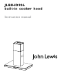
JLBIHD906
built-in cooker hood
Instruction manual
Important Safety Information
It is most important that this instruction manual should be retained with the appliance for future
reference. Should the appliance be sold or transferred to another owner, or should you move house and
leave the appliance, always ensure that the book is supplied with the appliance in order that the new
owner can get to know the functioning of the appliance and the relevant warnings. These warnings ha
ve been pr ovided in the inter est of saf ety .You MUST read them carefully before use or installation by a qualified person. If you are unsure of the meanings of these warnings contact the John Lewis
branch from which you purchased the appliance.
Installation
Child Safety
• Any installation work must be undertaken by a qualified and
competent person to the relevant National Standards.
• This appliance is designed to be operated by adults. Children should not be allowed to tamper with the controls
or play with the appliance.
• This hood must be installed in accordance with the installation instructions and all measurements must be adhered
to.
• If the cooker hood is installed for use above a gas appliance
then the provision for ventilation must be in accordance
with the Gas Safety Codes of Practice BS.6172, BS.5440
and BS.6891 (Natural Gas) and BS.5482 (LP Gas) 1994,
the Gas Safety (Installation & Use) Regulations, the Building
Regulations issued by the Department of the Environment,
the Building standards (Scotland) (Consolidated) Regulations issued by the Scottish Development Department.
• The fan motor of this cooker hood incorporates a cut-out
device which will operate if the cooker hood is installed
below the minimum height recommended under section
‘Clearance Height’, or if the motor becomes overheated.
If the cut-out device is activated, switch off the fan motor
and allow the cooker hood to cool. The cut-out device will
reset itself when the fan motor has cooled significantly.
• It is dangerous to alter the specifications or modify this
product in any way.
• When installed between adjoining wall cabinets the wall
cabinets must not overhang the hob.
• If the room where the hood is to be used contains a fuel
burning appliance such as a central heating boiler then its
flue must be of the room sealed or balanced flue type.
• If other types of flue or appliances are fitted ensure that
there is an adequate supply of air to the room.
• Hoods can be used safely with appliances connected
to a chimney if the room and/ or flat (air/environment
combination) is ventilated from outside using a suitable
ventilation hole approximately 500-600cm² large to avoid
the possibility of a depression being created during operation of the hood
• The ducting system for this appliance must not be connected to any existing ventilation system which is being
used for any other purpose.
• Do not install above a cooker with a high level grill.
Use
• This product is for domestic use only.
• Never leave frying pans unattended during use as overheated fats and oils might catch fire.
• Never do flambé cooking under this cooker hood.
• Do not leave naked flames under the hood.
• This cooker hood is designed to extract unpleasant odours
from the kitchen, it will not extract steam.
Maintenance and Cleaning
• This appliance can be a hazard if the synthetic paper and
charcoal filters are not replaced as recommended.
Service
• Under no circumstances should you attempt to repair the
appliance yourself. Repairs carried out by inexperienced
persons may cause injury or more serious malfunction.
Refer to your local Service Force Centre. Always insist
on genuine spare parts.
Environmental Information
• After installation please dispose of the packaging with due
regard to safety and the environment.
• The symbol
on the product or on its packaging
indicates that this product should not be treated
as normal household waste. Instead it shall be handed over
to an approved collection facility for the recycling
of electrical and electronic equipment. By ensuring
this product is disposed of correctly, you will help prevent
potential negative consequences for the environment and
human health, which could otherwise be caused by
inappropriate waste handling of this product. For more
detailed information about recycling of this product, please
contact your local city office, your household waste
disposal service or the shop where you purchased the
product.
2
Contents
For the User
Important Safety Information
Description of the Appliance
For the Installer
2
Electrical Connections
9
4
Electrical Requirements
Electrical Connection
9
9
Installing the Cooker Hood
5
Installation Requirements
Unpacking
Drilling the Ceiling/Support Shelf
Fixing the Frame
Extraction
Recirculation
Fitting the Chimney Stack
Fitting Hood body
5
5
6
6
7
8
8
8
Using the cooker hood
10
Cooker Hood Controls
To Operate
Recirculation
Extraction
10
10
10
10
Maintenance and Cleaning
12
External Cleaning
Cleaning the Comfort panels
Metal Grease Filters
Charcoal Filters
To Remove/Replace Charcoal Filter
Changing the Halogen Spot Lamp
12
12
12
13
14
14
Something Not Working
15
Repairs and After Sales Service
15
Guide to use the Instruction Manual
The following symbols will be found in the text to guide
you through the instruction book
Safety instructions
Step by step instructions
Environmental Information
This appliance complies with the followings E.E.C. Directives:
- 89/336 (Electromagnetic Compatibility Directive)
- 73/23 (Low Voltage Directive)
- 93/68 (General Directives)
and subsequent modifications
3
Description of the Appliance
4
Installation
Please ensure that when the appliance is installed it is easily accessible to an engineer in the event
of a breakdown.
All installations must comply with the local authorities requirements for the discharge of exhaust air.
Incorrect installation may affect the safety of this cooker hood.
Installation Requirements
Before installation check the wall to which the cooker hood is to be fitted for electric cables, water
pipes or gas.
The chimney hood must be installed according to the instructions suppliers below and by qualified and
competent personnel to the relevant National Standards.
This cooker hood is designed to be fixed to any horizontal surface over a cooking area, and can be used in the extraction
(ducted to the outside) or recirculation mode.
The installation work must be undertaken by a qualified and competent person.
The manufacturer disclaims any responsibility for damage due to incorrect installation of the cooker hood or if the
hood is not installed in compliance with relevant regulations controlling this type of installation.
Unpacking
��
Before unpacking the cooker hood position the carton
with the arrows pointing upwards as illustrated on the
carton.
The cooker hood is made up of the following components:
����
��
Ref. Q.ty Product Components
1
1
2
2.1
2.2
7.1
1
1
1
1
7.1a
7.1b
9
10
14
14.1
15
24
25
1
1
1
1
1
2
1
1
2
Hood Body, complete with: Controls, Light,
Blower, Filters
Telescopic Chimney comprising:
Upper Section
Lower Section
Telescopic frame complete with extractor,
consisting of:
Upper frame
Lower frame
Reducer Flange ø 150-120 mm
ø120-125 Ducting flange
Recirculation extension ducting
Recirculation extension ducting
Recirculation spigot
Junction box
Pipe clamps
���
����
��
����
6
2
4
1
Screws 2,9 x 9,5
Screws 2,9 x 6,5
Screws M6 x 10
Drilling template
�
��
���
�
���
��
��
���
Ref. Q.ty Installation Components
12c
12e
12f
21
��
���
��
���
���
�
Q.ty Documentation
1
Instruction Manual
���
5
Installing the Cooker Hood
In all cases where the ceiling is not strong
enough at the suspension point, the installer
must provide strengthening using suitable
plates and backing pieces anchored to the
structurally sound parts.
Drilling the Ceiling/Support
Shelf
• Use a plumb line to mark the centre of the hob on the
ceiling/support shelf.
• Place the drilling template 21 provided on the ceiling/
support shelf, making sure that the template is in the
correct position by lining up the axes of the template
with those of the hob.
• Mark the centre of the holes in the template.
• Drill the holes at the points marked:
• For concrete ceilings, drill for plugs appropriate to the
screw size.
• For hollow brick ceilings with wall thickness of 20
mm: drill ø 10 mm (immediately insert the Dowels
not provided).
• For wooden beam ceilings, drill according to the wood
screws used.
• For wooden shelf, drill ø 7 mm.
• For the power supply cable feed, drill ø 10 mm.
• For the air outlet (Ducted Version), drill according to
the diameter of the external air exhaust duct connection.
• Insert two screws of the following type, crossing them
and leaving 4-5 mm from the ceiling:
• For concrete ceilings, use the appropriate plugs for the
screw size (not provided).
• For Cavity ceiling with inner space, with wall thickness
of approx. 20 mm, Screws (not provided).
• For wooden beam ceilings, use 4 wood screws (not
provided).
• For wooden shelf, use 4 screws with washers and nuts
(not provided)
Fixing the Frame
• Loosen the two screws fastening the lower chimney and
remove this from the lower frame.
• Loosen the two screws fastening the upper chimney
and remove this from the upper frame.
If you wish to adjust the height of the frame, proceed as
follows:
• Remove the eight metric screws joining the two columns, located at the sides of the frame.
• Adjust the frame to the height required, then replace
all the screws removed as above.
• Insert the upper chimney stack from above, and leave it
running free on the frame.
�
�
�
�
6
• Lift up the frame, fit the frame slots onto the screws
up to the slot end positions.
• Tighten the two screws and fasten the other two screws
provided with the hood.
Before tightening the screws completely it is possible to adjust
the frame by turning it. Make sure that the screws do not
come out of their seats in the slotted holes.
• The frame mountings must be secure to withstand the weight of the hood and any stresses
caused by the occasional side thrust applied to
the device.
On completion, check that the base is stable,
even if the frame is subjected to bending.
Extraction (Ducted)
The cooker hood is more effective when installed in the
extraction mode (ducted to the outside).
Venting kits may be purchased through your local John
Lewis store, and must be evacuated through an outside
vent of ø125 (5ins) or ø150mm (6ins).
The ducting used must be manufactured from fire
retardent material conforming to the relevant British
Standard or DIN 4102-B1.
When the cooker hood is ducted to the outside
the charcoal filter must be removed.
Fitting the Ducting
• Fit the ø150mm (6ins) ducting to the spigot on top of
the hood body as illustrated.
• When using ø125mm (5ins) ducting fit item 9 and 10
on to the spigot on the top of the hood body as illustrated.
• For the best performance use the shortest possible run
of ducting and we recommend the use of rigid pipe in
preference to flexible hose as this will improve the flow
of air while reducing turbulence, which causes noise and
a loss of performance.
• If the room where the cooker hood is to be used contains
a fuel burning appliance such as a central heating boiler,
then its flue must be of the "room sealed" or "balanced
flue" type.
• If other types of flue or appliances are fitted ensure that
there is an adequate supply of air to the room.
• The cooker ducting when fitted in the extraction mode
must never be connected to central heating flues, radiators
or water heaters.
�����
��
�����
��
���
10
�
7
��
Recirculation Mode
����
The cooker hood is supplied specified for use in the recirculation mode, with the charcoal filter fitted.
In the recirculation mode contaminated air is passed through
the charcoal filter to be purified and recirculated into the kitchen through the grille outlets on either side of the chimney.
• Assemble the two halves of the ducting extension pipe
item 14.
• Push-fit the extension pipe onto the ducting spigot on
top of the canopy.
• Push-fit the recirculation adapter item 15 on to extension
pipe item 14.
• Insert the recirculation outlet extensions item 14.4 into
the recirculation adapter item 15.
• The recircualtion grilles item 8a and 8b must be fitted
after the lower chimney item 2.2 has been fitted.
• Ensure the activated charcoal filter has been fitted.
��
Chimney Stack
The chimney consists of two sections.
The lower chimney measures 740mm and the upper chimney (with the recirculation grilles on either side) measures
215mm. The overall installed measurement is min. 740
- max 940mm.
Fitting the Chimney
• Position the upper chimney section and fix the upper
part to the frame using the 2 screws 12c (2,9 x 9,5)
provided.
• Similarly, position the lower chimney section and fix the
lower part to the frame using the 2 screws 12c (2,9 x
9,5) provided.
• When installed in the recirculation mode the ducting outlet
extension pieces 14.1 should align with the rectangular
holes in each side of the chimney.
• Position the recirculation grilles 8a and 8b so the slats
face in a forwards and upwards direction.
���
��
��
���
���
Fitting the Hood Body
• Before fixing the hood body to the frame:
• Pull the Comfort Panel to open it.
• Disconnect the panel from the hood canopy by sliding
the fixing pin lever.
• Remove the grease filters from the hood body.
• Remove any activated charcoal filters.
• From below, use the 4 screws 12f (M6 x 10)
8
Electrical Connections
THIS APPLIANCE MUST BE EARTHED
Electrical Requirements
Any permanent electrical installation must comply with the
latest I.E.E. Regulations and local Electricity Board regulations.
For your own safety this should be undertaken by a qualified
electrician e.g. your local Electricity Board, or a contractor
who is on the roll of the National Inspection Council for
Electrical Installation Contracting (NICEIC).
Electrical Connection
Before connecting to the mains supply ensure that the mains
voltage corresponds to the voltage on the rating plate inside
the cooker hood.
• Remove the grease filters (see paragraph Maintenance)
being sure that the connector of the feeding cable is
correctly inserted in the socket placed on the side of
the fan.
• Push fit the Cmd connecter on the cable from the motor
housing to the one from the control box.
• Connect the lights connector Lux.
• Place both the Lux and Cmd connectors in the junction
box 24 and close it using the two screws 12e (2,9 x 9,5)
provided.
• Fix the junction box to the hood body using the two
screws 12c (2,9 x 6,5) provided.
• For the recirculation version, fit the activated charcoal
odour filter.
• Replace the grease filters.
��
���
This appliance is fitted with a 3 core mains cable and must
be permanently connected to the electricity supply via a
double-pole switch having 3mm minimum contact gap on
each pole. A Switched Fuse Connection Unit to BS1363 Part
4, fitted with a 3 Amp fuse, is a recommended mains supply
connection accessory to ensure compliance with the Safety
Requirements applicable to fixed wiring instructions.
This appliance conforms to BS 800: 1988 and EEC Directive
No. 78 308 regarding suppression of radio and television
interference.
���
���
���
9
Using the cooker hood
The cooker hood is designed to extract unpleasant odours from the kitchen, it will not extract steam.The appliance
can be installed to recirculate or extract contaminated air.
To Operate
Select the required fan speed and light if required.
Recirculation
In the recirculation mode the contaminated air enters the cooker hood through the grease filters. The air is cleaned
by passing through the charcoal filters before being passed back into the kitchen through the grilles in either side
of the chimney stack.
Extraction
In the extraction mode the contaminated air enters the cooker hood passing through the grease filters and is passed
out through the ducting into the atmosphere.
To obtain the best performance when cooking it is advisable to switch the cooker hood on for a few minutes before
you start cooking and leave it running for about 15 minutes after finishing.
When used in the ducting mode the charcoal filters are not required.
Never do flambé cooking under this cooker hood.
Never leave frying pans unattended during use, as over-heated fats and oils can catch fire.
Do not leave naked flames under the cooker hood.
Ensure heating areas on your hob are covered with pots and pans when using the hob and cooker hood
simultaneously.
Cooker Hood Controls
The hood can be switched on by pressing the required speed button without having to select 1 button.
� �� �� �� �� �� �
The functions of touch controls are explained on the next page
10
Touch
control
L
T1
T2
T3
Basic functions
Dual Function
When briefly pressed it switches the lighting system on and off.
Indicator lights
Touch control unlit
When pressed for 2 seconds it switches
the electroluminescent lighting on Touch control unlit
and off. This function is independent
from the basic functions of the control
unit. It is therefore possible to switch on Touch control lit
simultaneously the hood lighting and the
electroluminescent lighting. During the
electroluminescent lighting mode the Touch control unlit
touch control is unlit.
When pressed the motor is stopped, regard- Touch control lit
less of the speed it is set to.
Touch control unlit
When pressed the motor is set to the first
speed
By a brief pressing the motor is set to the
Touch control lit
second speed.
By pressing the touch control for approximately 2 seconds the Delay function is
enabled, i.e delayed shutdown of the
appliance ensuring a complete elimination of the residual odours. This function
can be activated at OFF-position and at
1°, 2° and 3°speeds. It can be stopped in Flashing touch
advance by pressing any of the touch control
controls (T) with the exception of T3.
The Delay function works according to
the following scheme:
1°speed / OFF = 20 minuets
2°speed = 15 minutes
3°speed = 5 minutes
T4
T5
F
When pressed the motor is set to the
third speed
When pressed the motor is set to the boost
option timed to 5 minutes. At the end of 5
minutes of boost option the hood starts again
at the speed it was set to previously. If the
hood is in the OFF-position and the boost
option is selected, after 5 minutes the speed
is reduced to setting 1 (T2).
Lights off
Lights off
Lights on
Electroluminescent lighting on
Motor on
Motor off
Touch control lit
Second speed on
Delay function on
Touch control lit
Touch control lit
When pressed for 4 seconds it resets the filter Touch control lit
alarm signal indicated by flashing of the touch
control T1. This procedure can be carried
out only when the motor is stopped.
Flashing touch
control
Metal grease filters saturation alarm.
Metal grease filters need to be washed.
The alarm starts up after 100 working
hours.
Charcoal odour filter saturation alarm.
Charcoal filter has to be replaced and
metal grease filters washed. The alarm
starts up after 200 working hours. (Activation; check the paragraph “Charcoal
filter”)
11
Maintenance and Cleaning
Before carrying out any maintenance or leaning isolate the cooker hood from the mains
supply.
The cooker hood must be kept clean, as a
build up of grease or fat can be a fire hazard.
External cleaning
Wipe the cooker hood frequently with warm soapy water
using a mild detergent.
Never use scouring pads or abrasive cleaners.
Never use excessive amounts of water when
cleaning particularly around the control panel.
Cleaning the Comfort Panels
• Pull the Comfort Panel to open it.
• Disconnect the panel from the hood canopy by sliding
the fixing pin lever.
• The comfort panel must never be washed in a dishwasher.
• Clean the outside using a damp cloth and neutral liquid
detergent.
• Clean the inside as well using a damp cloth and neutral
detergent; do not use wet cloths or sponges, or jets of
water; do not use abrasive substances.
• When the above operation has been completed, hook the
panel back to the hood canopy and close it by turning
the knob in the opposite direction.
Metal Grease Filters
The grease filters absorb grease and dust during cooking
to help keep the cooker hood clean inside, and should
be cleaned when the F - touch control lights up or at
least every 2 months of operation, or more frequently
for particularly heavy usage.
12
Cleaning the filters
• Pull the Comfort Panel to open it.
• Remove the filters one by one pushing them towards
the back side of the unit and simultaneously pulling
downwards.
• The metal grease filters can be washed, by hand, in mild
soapy water or in a dishwasher. Allow to dry completely
before refitting. Any kind of bending of the filters must
be avoided when washing them.
• When fitting the filters into the hood pay attention that
they are mounted in correct position and that the handle
faces outwards.
• Close the comfort panel.
Alarm signal reset
• Stop the motor.
• Press the F -touch control for at least 4 seconds
until the T1 -touch control flashes.
Before carrying out any maintenance or
cleaning isolate the cooker hood from the
mains supply.
Charcoal Filters
In the recirculation mode the charcoal filters absorb
smells and unwanted odours.
This charcoal filters cannot be washed or regenerated,
and must be replaced when the F touch control starts
to flash, or at least once every 4 months. The alarm is
only triggered when the motor is on.
Enabling/Disabling the alarm
signal
• In Recirculation Version Hoods, the Filter saturation Alarm
must be enabled at the time of installation or later.
• Switch off the lights and the motor.
• Disconnect the mains power supply to the hood by
removing the motor unit power supply cable connector,
switching off the power supply at the Mains or turning
the Main switch off.
• Restore the connection, pressing and holding T2.
• Release the touch control, touch controls L, T2 and F
will light up normally.
• Within 3 seconds press the touch control F until the
key itself flashes to confirm as follows:
• 2 flashes – Charcoal odour Filter saturation Alarm
ENABLED
• 1 flash - Charcoal odour Filter saturation Alarm
DISABLED
13
To Remove/Replace the Charcoal Filters
• First remove the metal grease filters.
• Remove the saturated activated charcoal filter by releasing
the fixing hooks as illustrated.
• Position the new charcoal filter in the position marked
and while holding the filter replace the fixing hooks as
illustrated
Reset the alarm signal
• Stop the motor.
• Press the touch control F for at least 4 seconds,
until the touch control T1 flashes.
This appliance can be a possible fire hazard if
the grease and charcoal filters are not cleaned
and replaced as recommended.
Changing the Halogen Spot
Lamp
• Unscrew the two screws to release the metal surround.
• Remove the lamp from the holder by pulling the lamp
downwards.
• Replace the lamp with a new one of the same type, making sure that you insert the two pins properly into the
housings on the lamp holder.
• Replace the Support, fixing it in place with the two screws
removed as above.
Replacement filters and light bulbs can be obtained from your local Service Force Centre.
14
Something not Working
If the appliance is not working correctly, please carry out the following checks, before contacting your local Service
Force agent.
IMPORTANT: If you call out an engineer to a fault listed below, or to repair a fault caused by incorrect use or installation, a charge will be made even if the appliance is under guarantee.
Symptom
Solution
The cooker hood will not start
• Check the hood is connected to the electricity supply.
• Make sure the switch is in the ‘ON’ position.
The cooker hood is not working effectively
• Check that the fan speed is set high enough for the task
• Ensure the grease filter is clean.
• Ensure the kitchen is adequately vented to allow the entry
of fresh air.
• If set up for recirculation, check that the charcoal filter is
still effective.
• If set up for extraction, check that the ducting and outlets
are not blocked.
The cooker hood has switched off during
operation
• The safety cut-out device has been tripped.
• Tum off the hob and then wait for the device to reset.
Repairs and After Sales Service
In the event of your appliance requiring service, or if
you wish to purchase spare parts, please contact our
extended warranty administrators by telephoning:
0870 01 07887
When you contact the Service Force Centre you will
need to give the following details:
1. Your name, address and post code
2. Your telephone number
3. Clear and concise details of fault
4. The model and serial number of the appliance (found
on the rating plate - see picture)
They will give you details for your local Service Force Centre.
Before calling out an engineer, please ensure you have
read the details under the heading “Something Not
Working”.
Your oven is covered by a 3 year parts and labour
guarantee (see separate details given at point of sale).
Please retain your purchase receipt safely for the service
engineer to verify the purchase details.
5. The purchase date.
Please note that a valid purchase receipt is required for
in-guarantee service calls.
15
John Lewis Partnership
171 Victoria Street
London SW1E 5NN
www.johnlewis.com
436003471_03 - 070625
0607