1
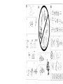
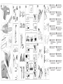
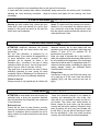
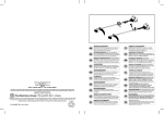
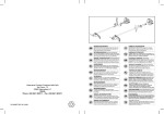
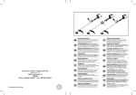
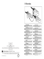
Electrolux Outdoor Products
Via Como 72
23868 Valmadrera (Lecco)
ITALIA
Phone + 39 0341 203111 - Fax +39 0341 581671
www.electrolux.com
Our policy of continuous improvement means that the specification of products may be altered from time to time without prior notice.
Electrolux Outdoor Products manufacture products for a number of well known brands under various registered patents, designs and
trademarks in several countries.
© Electrolux Outdoor Products
The Electrolux Group. The world’s No.1 choice.
The Electrolux Group is the world’s largest producer of powered appliances for kitchen, cleaning and outdoor use. More than 55 million
Electrolux Group products (such as refrigerators, cookers, washing machines, vacuum cleaners, chain saws and lawn mowers) are
sold each year to a value of approx. USD 14 billion in more than 150 countries around the world.
PN. 249411 REV. 03 (01/05)
A. GENERAL DESCRIPTION
1)
2)
3)
4)
5)
6)
7)
8)
9)
10)
11)
12)
13)
14)
15)
16)
Rear handle
Rear hand guard
Front handle
Front hand guard/chain brake lever
Chain tensioner knob/screw
Chain tensioner pin
Oil tank cap
Oil tank inspection gauge
Air vents
Cable
Manual
Switch
Switch block
Chain
Drive tooth
Cutting link
17)
18)
19)
20)
21)
22)
23)
24)
25)
26)
27)
28)
29)
30)
31)
Cutting depth gauge
Cutting tooth
Bar
Chain cover
Pinion
Chain catcher
Bar retaining screws
Bar retaining knob / nuts
Nose sprocket
Guide bar cover guard
Spiked bumper
Chain tensioner pin housing
Lubrication hole
Guide groove
Oil pump adjustment knob
LEGEND:
1)
Example of identification label
2)
3)
4)
5)
6)
7)
8)
9)
10)
11)
12)
13)
14)
15)
16)
Guaranteed noise level according to directive
2000/14/EC
Double insulation
CE marking of conformity
Protection degree
Rated frequency
Rated power
Alternate current
Rated voltage
Type
Prefix
Product code
Year of manufacture (last two figures; e.g. 04=2004)
Maximum bar length
Manufacturer’s name and address
Serial number
Model
ENGLISH – 1
B. SAFETY PRECAUTIONS
MEANING OF SYMBOLS
Warning!
Read the
instruction
manual
carefully
Protective
boots
Protective
goggles or
visor, protective
helmet and
hearing
protection
Do not dispose
inappropriately
of the machine.
Deliver it to an
authorized
organization.
Always grip the
machine with
two hands
Kickback
danger
Do not expose
to rain or
moisture.
Protective cutproof gloves
Chain oil
Protective long,
cut-proof
trousers
Refrain from
Chain brake:
deactivated,
activated
Turn the
machine off
Disconnect the
plug if the cable
is damaged
Correct
direction of the
cutting teeth.
Manual use. All persons using this machine must
read the user manual completely with extreme care,
(and where possible must also be present during a
practical demonstration on correct machine use) in
order to be familiar with all user operations in
complete safety, as well as all the cutting techniques
possible with this machine. For this reason, the user
manual must be included with the machine in the
case of sale or loan to another person. Please
ENGLISH - 2
remember that ALL parts of the user manual are
important, as they are included to help prevent injury
to the user and damage to the machine. Following
correct manual procedure does not necessarily
prevent all danger risk, but certainly reduces the
probability or effects of injury or damage.
Manual layout: Section B is divided into various
parts that are referred to in the rest of the manual and
marked with the “Warning” sign, followed by the
reference number of the corresponding component to
draw the reader’s attention to the main safety
procedure linked with that particular situation; the
machine parts shown in “A
– GENERAL
DESCRIPTION” are indicated in italics in the text for
easy identification.
Precautions prior to machine use. Never permit
this machine to be used by any persons who are not
perfectly familiar with the manual instructions, who
are not in good physical and mental condition, who
are not sufficiently competent and by children (local
regulations may sometimes limit the age of operators
permitted to use the machine). Inexperienced
persons must follow a training period operating on a
saw horse only. The user is responsible for any
accidents that may cause injury to other persons and
damage to property, as well as any other type of
danger risk. The machine must never be used for
operations other than those specifically described in
this manual, and exclusively with the bars and chains
indicated. This machine must never be used when
users are tired, or not in good physical condition, or if
under the effect of any substance that may alter their
physical or mental condition (pharmaceuticals,
alcohol, drugs etc.) Make certain that the user knows
how to stop the motor and chain in case of necessity.
Take great care and pay close attention at all times
when using this machine, following all general
behaviour rules according to good sense.
1. Control checks. Control the machine with care
before use each time, especially if it has been subject
to strong impact, or if it shows any signs of
malfunction. Check that the machine has been
assembled correctly, that all components are in
correct condition and perfectly clean. Perform all
operations described in the chapter “Maintenance –
before each use”. Make sure that all spanners and
tools used for adjustment operations have been
removed, that all screws and nuts are in their correct
housing and tightened correctly, and that the bar and
the chain are mounted correctly. If even one single
condition described above is not satisfactory DO NOT
USE the machine.
2. Repairs and Maintenance. All the machine parts
that can be replaced personally, are clearly explained
in the “Assembly / disassembly” instructions chapter.
In the case of damaged or worn components, always
use exclusively original homologated accessories and
spare parts that are available from official distributors.
Where necessary, all other machine parts must be
replaced exclusively by an Authorised Service
Centre. All danger risks increase considerably if
maintenance operations are not performed regularly,
not performed by competent professional personnel,
or if non-original accessories /spare parts are
mounted on the machine. In any of the cases
described above, the manufacturer will not be held
responsible for any injury to persons or damage to
property. In the case of any doubt, please contact an
Authorised Service Centre.
3. Maintenance in complete safety. All
maintenance, assembly, disassembly and oil tank
filling operations must be performed with the machine
set in a stable position on a flat solid surface and with
the cable plug disconnected from the electricity
supply (unless this is explicitly specified otherwise).
The chain must be arrested and the user must wear
suitable protective gloves.
4. Clothing. When using this machine the user must
wear the following homologated individual protective
clothing : close-fitting protective clothing, safety boots
with non-slip soles, crush-proof toe puffs and cutproof protection; cut-proof vibration-proof gloves,
protective goggles or safety visor (remove protective
film where present); ear protection muffs; helmet (if
there is any danger of falling objects); some efficient
method to cover or tie hair back from shoulder length
(if hair is longer than shoulders); dust-proof mask. DO
NOT WEAR shorts, loose clothing, unbuttoned
clothing, or any jewellery that could become caught in
moving machine parts. Do not wear sandals and
never work bare-footed.
5. Health precautions – Vibrations and Noise
levels. Avoid using the machine for long periods of
time: the noise and vibrations can be dangerous
causing irritation, stress, fatigue and hypacusia
(hearing problems). Prolonged machine use exposes
the user to vibrations that can generate “white finger
phenomenon” (Raynaud’s Phenomenon), carpal
tunnel syndrome and similar disturbances. This can
lead to a lack of sensitivity in the hands making it
difficult to notice changes in temperature as well as
causing numbness. When using the machine
regularly or in continuation, the user must control the
condition of his hands very carefully. If any of the
symptoms described above appear, consult a doctor
immediately.
ENGLISH – 3
6. Health precautions – Chemical agents. Avoid all
chain oil contact with skin and eyes.
7. Health precautions - Electricity. All extension
cords, plugs, and electricity lines must be
homologated, to standard and in compliance with
current regulations. Make sure that the main line to
which the machine is connected is equipped with a
residual current device (RCD) with a current capacity
no higher than 30mA. Make sure that all cables,
plugs, and the residual current device are in correct
working condition, that they comply with required
characteristics, are mounted or hooked up correctly
and are perfectly clean. Never disconnect the
machine from the main line by pulling on the cable.
Never use or store the machine and extension cord in
damp environments. If the cable is damaged in any
way, disconnect immediately from the main line
socket, taking great care not to touch any exposed
wires. Avoid all contact with grounded surfaces when
using the machine (metal piping, cables, lightening
conductors, etc). When working outdoors, all
extension cords attached to the machine must be
homologated for use out of doors. Avoid tying any
knots in electric cables and never use rolled up
extension cords.
8. Health precautions - Heat. During use pinion
and chain reach very high temperatures, take care
not to touch these parts while hot.
9. Health precautions – Sharp or moving
parts. Never touch the chain except when the
machine is switched off; in any case, always take
great care since the chain is very sharp and can cut
even when stopped. Remember that the chain will
continue to rotate for a short time after the machine
has been switched off.
10. Work area. Control the whole work area carefully
to check for any danger source (e.g.: roads, paths,
electric cables, dangerous trees, etc) Take special
care when working on sloping ground. Cluttered
areas can lead to injuries: before using the machine
remove any stones, glass, cables, metal components,
cans, bottles and any other foreign matter from the
work area. Also take into consideration any danger
risks that may not be noticed because of machine
noise. Make sure that a second person is within
calling distance in the case of accident. When
working in isolated areas, always carry a first aid kit
and make sure you have advised others of your exact
location.
ENGLISH - 4
11. Work operations
Never start work with the machine before
performing the following: remove the giude bar
cover guard; make sure that a sufficient amount of oil
has reached the chain; make sure you have a
planned retreat path from falling trees (when cutting
trees).
It is strictly forbidden to use the machine for:
moving branches or roots; in cases where there is
any danger that the chain may come into contact with
the ground, electric protection, or piled wood; for
cutting very thin branches or bushes (these will break
easily and can whip bystanders or the user causing
serious injury); for felling trees without adequate
training and equipment (correct ropes, hooks, etc);
starting sawing operations with the blade already
engaged in a previous groove or slit; using the
machine while standing on stepladders or other
unstable surfaces; using the machine in extreme
weather conditions, inclement weather, with reduced
visibility and insufficient lighting (very low
temperatures, very hot damp climates, fog, rain, wind,
at night, etc.); using the machine with arms stretched:
work must always be performed in a manner to
ensure that the user can react immediately to
unexpected conditions; it is forbidden to leave the
machine unguarded; permitting others to touch the
cable, extension cord , or the machine; forcing the
machine during cutting action (this can lead to motor
damage or loss of control over the machine); blocking
the switch or the switch block with adhesive tape or
other materials.
Always remember to: cut wood only (never cut
plastic, metal, or other materials); make sure that the
switch is NOT turned ON before inserting the plug in
the socket or releasing the chain brake lever; make
sure that the chain is not in contact with any objects
at the moment the switch is turned ON; Keep all
bystanders and animals well clear of the work area
(where necessary, fence off the area and use
warning signs) at a minimum distance of 2.5 m times
the trunk height; in any case no less than ten meters.
Wherever possible use a vice or a saw horse to block
the wood to be cut; always hold the machine as
follows: Grip the front handle with the left hand and
the rear handle with the right hand, closing the thumb
and other fingers firmly around the handle (during
use, the machine could slide forwards or backwards,
or create a reverse action, provoking a kickback
reaction: holding the machine correctly reduces the
risk of loosing control over the tool); Always make
sure that the cable/ extension cord is kept behind the
user, controlling that it does not create a source of
danger for the user or for other persons, and check
that it cannot be damaged (by heat, sharp objects,
sharp edges, oil, etc); Always assume a stable
standing position on both legs; keep the handles dry
and clean; during use keep all body parts and
clothing well clear of the chain; turn off the switch,
wait until the chain has stopped turning, and activate
the chain brake lever before putting down the saw;
never attempt to cut at heights over shoulder height;
always handle the machine with the utmost care;
check that the oil level never drops below MIN level,
controlling frequently, before and during use; Always
remain on the left hand side of the machine during
use, and take great care if the bar needs to be
inserted in a previously cut slit; remove the bar from
the slit when the chain is still in rotation.
12. Transport and storage precautions. Each time
the work area is changed to another location,
disconnect the machine from the main line and
activate the chain brake lever. Mount the guide bar
cover guard each time before transporting or storage.
Always carry the machine by hand with the bar facing
backwards, or when transporting the machine in a
vehicle, always attach it securely to prevent damage.
Never carry the machine by the cable. After use,
store the machine in a dry, high place, far from heat
sources and out of reach of children.
13. Precautions against fire risk. Never use the
machine in areas where there are naked flames,
inflammable or potentially explosive materials.
14. Kickback reaction. The kickback reaction
consists of a violent upwards-reverse action of the
bar towards the user. This generally occurs if the
upper part of the bar nose (called the “kickback
danger zone”) comes into contact with some object,
or if the chain is blocked in the wood. The kickback
reaction is a very quick sudden motion along the bar
cutting plane (generally in an upward direction, but
this also depends on the machine position during
cutting action). Kickback can make the user loose
control of the machine provoking dangerous and
even mortal accidents (i.e: if the saw with the chain in
rotation is thrust back against the user). The chain
brake lever and other safety devices are not sufficient
to protect the user against injury: the user must be
well aware of the conditions that can provoke the
reaction, and prevent them by paying very close
attention according to experience, together with
prudent and correct machine handling (for example:
never cut several branches at a time because this
can cause accidental impact on the “kickback danger
zone”; never mount incorrect bars or chains; make
sure the chain is always sharp and sharpen
according to correct methods, because incorrect
sharpening can cause kickback; when choosing the
bar, remember that the smaller the nose radius, the
smaller the kickback danger zone).
C. SAFETY EQUIPMENT DESCRIPTION
SWITCH BLOCK
Your machine is equipped with a device (fig.1) that
when deactivated, stops the switch from being
pressed thus preventing accidental start-up.
CHAIN BRAKE ACTION ON SWITCH RELEASE
(for ES18 models only)
Your machine is equipped with a device that blocks
the chain immediately as soon as the switch is
released; If this device should not work at any time,
the machine must NOT be used, and must be taken
to an Authorised Service Centre.
1,3,6,8,12
FRONT HAND GUARD / CHAIN BRAKE LEVER
The front hand guard (fig.2) is designed to prevent
your left hand from coming into contact with the chain
(on condition that the machine is held correctly
according to instructions) . The front hand guard also
acts as a chain brake, including a device that blocks
the chain in a few fractions of a second in the case of
kickback. The chain brake is released when the front
hand guard is pulled backwards and blocked in
position (the chain is able to move). The chain brake
is activated when the front hand guard is pushed
forward (the chain is blocked).
ENGLISH – 5
The chain brake can be activated in two modes: the
first using the left wrist by pushing forwards, or when
it comes into contact with the brake system as a result
of kickback; or by inertia, in the case of particularly
violent kickback.
When the machine is used with the bar in horizontal
position, for example during tree felling, the chain
brake offers less protection, because it can be
activated by inertia only, since the user’s hand is
outside the range of action of the front hand guard
(fig.3).
N.B.: When the chain brake is activated, a safety
switch cuts off all current to the motor.
CHAIN CATCHER
This machine is equipped with a chain catcher (fig.4)
located under the pinion. This mechanism is
designed to arrest the backward chain movement in
the case of chain breaking or derailing. These
situations can be avoided by ensuring correct chain
tension (Refer to chapter “D. Assembly/disassembly”).
REAR HAND GUARD
This acts to protect(fig.5) the hand in the case of
chain breaking or derailing.
D. ASSEMBLY / DISASSEMBLY
2,3,6,7,8,9,12
BAR AND CHAIN ASSEMBLY
Assembly methods change according to the type of your machine- so please take care to refer to the illustrations
and machine type marked on the label (A- Legend – 9 [ES15 / ES16 / ES18] ), Take great care when
assembling to ensure this is performed correctly.
FOR ES 15 / ES 16
FOR ES 18
1. Control that the chain brake is not activated. If so, deactivate it.
2a. Unscrew the bar retaining nuts and remove 2b. Unscrew the bar retaining knob and remove the
the chain cover.
chain cover.
3a. Mount the bar on the bar retaining screws
3b. Mount the bar on the bar retaining screw pushing
pushing it as far backward towards the pinion
it as far backward towards the pinion as possible.
as possible.
4. Oil the chain, then position it over the pinion, making it slide into the bar guide groove, beginning with
the upper part. Attention! Control that the sharp side of the cutting teeth face in a frontward direction on
the upper part of the bar; Set the chain tensioner pin in the chain tensioner pin housing. Mount the chain
cover making sure that the drive teeth of the chain are engaged in the pinion and in the guide groove.
5a. Close the bar retaining nuts, screwing by 5b. Screw the bar retaining knob loosely tightened.
hand.
6a. To spread the chain screw the chain 6b. To spread the chain screw the chain tensioner
tensioner screws in a clockwise direction, to knob in a clockwise direction, to loosen tension, screw
loosen tension, screw in an anti-clockwise in an anti-clockwise direction (when performing this
direction (when performing this operation operation maintain the bar nose raised upwards)
maintain the bar nose raised upwards)
7 Spread the chain until the tension is correct; that is, when the chain is pulled upwards, the drive tooth
rise to the same level as the bar. (the chain must never droop on the underside of the bar)
8a. Tighten the bar retaining nuts using an 8b. Tighten the bar retaining knob strongly.
appropriate tool.
Tensioning the chain too tightly will overload the motor and cause damage, insufficient tension can provoke
chain derailing, whereas a chain tightened correctly provides the best cutting characteristics and prolonged work
life. Check the tension regularly because the chain length tends to stretch with use (especially when the chain is
new; after the first assembly, the chain tension must be controlled after 5 minutes machine operation); in any
ENGLISH - 6
case do not tighten the chain immediately after use, but wait until it cools down.
In cases where the loosened chain needs to be adjusted, always unscrew the bar retaining nuts / knob before
adjusting the chain tensioning screw/knob ; adjust the tension and tighten the bar retaining nuts /knob
accordingly.
E. START-UP AND ARREST
Start-up: grip both handles firmly, release the chain
brake lever, press and maintain the switch block
pressed in, then press the switch (at this point the
switch block can be released).
1,4,5,6,7,8,9,11,12,13
Arrest: The machine will stop whenever the switch is
released. In the case where the machine does not
stop, activate the chain brake, disconnect the cable
from the main line socket and take the machine to the
Authorised Service Centre.
F. BAR AND CHAIN LUBRICATION
ATTENTION! Insufficient lubrication will provoke
chain breaking and can cause serious and even
mortal injury.
Bar and chain lubrication is performed by an
automatic pump. If your machine is equipped with an
oil pump adjustment knob (optional) the chain
lubrication can be adjusted as shown in the
illustration (fig.1), according to the type of cutting
operation in hand (dry wood – more oil, green wood less oil, long bar- more oil, short bar - less oil).
Take great care to ensure that the chain is always
sufficiently lubricated by never closing the pump
completely. Refer to “Maintenance” for indications on
ensuring that the chain oil is sufficiently distributed.
Choice of chain oil
Always use new oil only (special type for chains) with
G. MAINTENANCE
ATTENTION! In cases where work environments are
particularly dirty or dusty, the operations described
must be performed more frequently than mentioned
in the instructions.
Before each use
Control that the chain oil pump functions correctly:
direct the bar towards a clear surface at a distance of
about 20 centimetres; after the machine has run for
about a minute, the surface should show clear traces
of oil(fig.1).
3,6,7,8,9,12
adequate viscosity: the oil must adhere well and
guarantee good running properties in both winter and
summer. If chain oil is not available, EP 90
transmission oil can be used.
Never use waste oil because this is this harmful to
health, the machine and the environment. Make sure that
the oil is suitable for the temperature of the environment
where the tool will be used: For temperatures under 0°C
certain oils become denser, overloading the pump and
causing damage. Contact your Authorised Service
Centre for advice on oil choice.
Filling oil tank
Unscrew the oil tank cap, and fill the tank taking care
not to spill any oil (if this occurs clean the machine
carefully) (fig.2), and then screw the cap back on
tightly.
1,2,3,4,5,6,7,8,9,12,13
Check that excessive strength is not needed for
activating and deactivating the chain brake. Also
check that it is not activated too easily and that it is
not blocked. Then check chain brake function as
follows: release the chain brake, grip the machine
correctly and start up the machine, activate the chain
brake by pushing the front hand guard forward with
the left wrist or arm but without removing the hand
from the handle(fig.2). If the chain brake is working
correctly, the chain should be blocked immediately.
ENGLISH – 7
Check that the chain is sharpened correctly (See
below), in good working condition and that the
tension is correct. If the chain is irregularly worn, or if
the cutting teeth are only 3 mm high, the chain must
be replaced(fig.3).
Clean the air vents regularly to prevent motor
overheating.
Check that the switch and switch block function
correctly (to be performed with the chain brake
released): press the switch and the switch block and
control that they return to idle position as soon as
they are released; control that it is impossible to
press the switch without activating the switch block.
Check that the chain catcher and the right hand
guard are in correct condition without any visible
faults such as damaged material.
Every 2-3 hours of use
Control the bar condition, if necessary clean the
lubrication holes(fig.4) and the guide grooves(fig.5)
carefully; If the groove is worn or shows signs of deep
notching, it must be replaced. Turn the bar to ensure
even wear(fig.6). Clean the pinion regularly and check
that it has not been subject to excess wear(fig.7).
Lubricate the nose sprocket with bearing grease
through the hole shown in the illustration (fig.8).
Chain sharpening (When necessary)
If the chain does not cut correctly, or requires hard
bar pressure against the wood, and if the sawdust is
very fine, this is a sign that it is not sharpened
correctly. If the cutting action produces no sawdust,
this means the cutting edge has been worn
completely and the chain is pulverising the wood
during cutting. A well-sharpened chain crosses
through the wood without effort or pressure and
produces large long wood shavings.
H. CUTTING TECHNIQUES
When using the machine, prevent: (fig.1)
- cutting in conditions where the trunk could split
during cutting (wood under pressure, dry dead trees,
etc): sudden splitting can be very dangerous.
- the bar or the chain from becoming blocked in the
cutting notch: if this should occur, disconnect the
machine from the main electricity supply and try to
raise the trunk using an appropriate tool as a lever; do
not attempt to free the machine by shaking or pulling
as this could cause damage or injury.
ENGLISH - 8
The cutting side of the chain is composed of the cutting
link (fig.9) with a cutting tooth(fig.10) and a cutting limit
gauge(fig.11). The difference between these determines
the cutting depth; a file guide and a 4mm diameter round
file are needed to obtain good sharpening results; Follow
the instructions below: Once the chain has been
mounted and the tension is correctly adjusted, and the
chain brake is activated, position the file guide
perpendicular to the bar as shown in the
illustration(fig.12), filing the cutting teeth at the angle
shown(fig.13), always working from the interior towards
the exterior, lessening the pressure during the return
stage (it is very important to follow the instructions
perfectly: excessive or insufficient sharpening angles, or
an incorrect file diameter will increase the risk of
kickback.) To obtain higher precision on side angles, it is
advisable to position the file so that it exceeds the upper
cutter by about 0.5 mm. File all the teeth on one side first,
then turn the machine over and repeat the operation.
Make sure that after sharpening operations, all teeth are
the same length and that the height of the depth gauge is
0.6 mm lower than the upper cutter: check the height
using a proper template and file (with a flat file) all
protruding parts, rounding off the front part of the depth
gauge(fig.14), paying attention to not file the kickback
protection tooth(fig.15)
Every 30 hours use.
Take the machine to the Authorised Service Centre
for general revision and control check on brake
components.
PERIODS OF PROLONGED DISUSE
Always empty the fuel tank with the same precautions
used in filling it.
1,2,3,4,5,6,7,8,9,10,11,12,13,14
- situations that can lead to kickback reactions.
During machine use: (fig.1)
- When cutting on sloping ground, always work uphill
of the trunk to avoid being hit if the trunk should roll
downhill.
- Release the switch after each cutting action:
prolonged dry running of the motor will provoke
serious damage.
- When felling trees, always finish the job: a partially
cut tree could break and fall.
- At the end of each cutting operation the user will
notice a considerable change in the strength
necessary for controlling the machine. Great care
must be taken not to loose control .
Below is a description of two different types of cutting
operation:
Cutting action by pulling the chain (from top to
bottom) (fig.2) can lead to dangerous sudden
movement of the machine towards the trunk with
consequential loss of control. Where possible, use the
spiked bumper during cutting operations.
Cutting action pushing the chain (from bottom to top)
(fig.3) will lead to the danger of a sudden movement
of the machine in the direction of the user, with the
risk of hitting the user, or an impact of the “kickback
danger zone” on the trunk resulting in strong
kickback; extreme care must be taken when cutting in
this manner.
The safest method for using the machine, is to block
the log on a sawhorse, cutting from top to bottom, on
the portion outside the sawhorse. (fig.4)
Spiked bumper use.
Where possible, use the spiked bumper to ensure
safer cutting action: plant it in the bark or surface of
the trunk in order to maintain more control over the
machine.
Below are descriptions of typical cutting procedure to
be adopted for specific situations. However, these
should be assessed each time to calculate whether
the method is most suitable or not, in order to use a
method with the least possible risk.
Trunk on the ground. (Risk of touching the ground
with the chain once the bar has passed trough the
trunk). (fig.5)
Cut from top to bottom through the whole trunk.
Towards the end of the cut, proceed very carefully to
prevent the chain from hitting the ground. If it is
possible, cut 2/3 of the trunk, roll it over, and cut the
remaining third from top to bottom to limit the risk of
the chain touching the ground.
Trunk supported at one end only (Risk of trunk
breaking during cutting action). (fig.6)
Begin the cut from underneath for about 1/3 of the
diameter, and then finish the cutting action from the
top to meet the undercut.
Trunk supported at both ends. (Risk of pinching the
chain). (fig.7)
Begin the cut from above for about 1/3 of the
diameter, and then continue from underneath to meet
the overcut.
Tree felling.
ATTENTION! : Never attempt to fell a tree if you do
not have the necessary experience, and in any case
never fell trees that have trunks with a diameter larger
than the length of the bar ! This operation is reserved
for expert machine users with adequate equipment.
When felling a tree, the aim is to have the tree fall in
the most convenient position for the following limbing
and bucking operations. (Avoid trees falling on top of
other trees: Felling trees that are entangled with other
trees is a very dangerous operation).
First of all decide which is the best direction for the
tree to fall by evaluating the following: objects or other
plants around the tree, the inclination, the curve, wind
direction, and greatest branch concentration. Take
into account dead or broken branches that may break
off during felling creating a further danger risk.
ATTENTION! During tree felling operations in critical
conditions, always remove ear protection immediately
after cutting operations to be able to listen for unusual
noises and any warning signals.
Preliminary cutting operations and identifying the
retreat path.
Eliminate any branches that interfere with the job
(fig.8), starting from top to bottom, and then, always
keeping the trunk between the user and the machine
eliminate the more difficult branches afterwards, piece
by piece. Eliminate all plants that interfere with work
operations and control the area for possible obstacles
(rocks, roots, ditches,etc.) when planning the retreat
path (to follow during tree fall); Refer to the illustration
(fig.9) for the directions to be maintained (A. predicted
tree fall direction. B. Retreat path. C. Danger zone).
FELLING CUTS (fig.10)
In order to ensure that the user has complete control
over the tree fall, the cutting instructions are as
follows:
The cut that controls the fall direction of the tree is to
be executed first: First of all cut the UPPER PART of
the directional notch on the side the tree must fall.
Remain on the right hand side of the tree and cut
using the chain pull method; then cut the LOWER
PART that must meet the end of the upper part. The
depth of the directional notch must be ¼ of the trunk
diameter, with an angle of at least 45° between upper
ENGLISH – 9
and lower cut. The meeting point between the two
sides of the notch is called “directional cut line” This
line must be perfectly horizontal at right angles (90°)
to the felling direction.
The felling cut that provokes the tree fall, is performed
at 3 to 5 cm above the lower part of the directional
felling cut line, finishing at a distance of 1/10 of the
trunk from the notch. Remain on the left hand side of
the tree and cut using the chain pulling method and
the spiked bumper. Check that the tree does not
move in a direction other than that predicted for the
fall. As soon as possible insert a felling lever or
wedge into the cut. The uncut part of the trunk is
called the “hinge”, as it is intended to guide the tree
as it falls; in cases where the cuts are not sufficient,
not straight, or have been cut through completely, the
tree fall cannot be controlled (extremely dangerous!).
For this reason the various cuts must be performed
with great precision.
When cutting operations are completed the tree will
begin to fall. Where necessary help tree fall using
wedges or felling levers
.
Limbing
Once the tree has been felled, the trunk must be
limbed: in other words, the branches are removed
from the trunk. Do not underestimate this operation
because the large majority of kickback accidents
occur during this stage. For this reason pay close
attention to the position of the bar nose during cutting
operations and always work on the left hand side of
the trunk.
I. ENVIRONMENTAL INFORMATION
This section contains information useful for maintaining the characteristic of ecocompatibility included in the
origin design of the machine, and as regards proper use and disposal of chain oil
DESIGN
In the design stage, care was taken to develop an engine with reduced consumption and low emission of noise.
USE OF THE MACHINE
The operations of filling the oil tank should be carried out in such a way as to avoid spilling oil and contaminating
the soil and the environment.
DISPOSAL
Do not dispose inappropriately of the machine when it is no longer usable. Deliver it to an authorized
organization for proper disposal in compliance with the regulation in force.
on the product or on its packaging indicates that this product may not be treated as household
The symbol
waste. Instead it shall be handed over to the applicable collection point for the recycling of electrical and
electronic equipment. By ensuring this product is disposed of correctly, you will help prevent potential negative
consequences for the environment and human health, which could otherwise be caused by inappropriate waste
handling of this product. For more detailed information about recycling of this product, please contact your local
council office, your household waste disposal service or the shop where you purchased the product.
ENGLISH - 10
M. TROUBLESHOOTING TABLE
Motor does
not start
Make sure the main
line is powered
Make sure the machine
is properly plugged in
Make
sure
your
cable/ext. cord is not
damaged
Make sure that chain
brake is not activated
Check that chain is
properly assembled
Check
chain
lubrification as in
chapters F and G
Make sure that the
chain is sharp
Contact
your
authorised centre
Motor turns
with difficulty
or loses
power
The machine
starts but
does not cut
properly
z
z
Motor turns
improperly or
at reduced
speeds
Braking
devices do
not stop the
chain properly
z
z
z
z
z
z
z
z
z
z
ENGLISH – 11
N. DECLARATION OF CONFORMITY
The undersigned, authorized by E.O.P.I., declares that the following products model: type ES15, ES 15/1, ES
15/2, ES16, ES 16/1, ES18 starting from 2004 onwards, manufactured by E.O.P.I., Valmadrera, Italy, comply
with European Directive: 98/37/EEC (Machine Directive), 93/68/EEC (EEC Marking Directive) & 89/336/CEE
(Electromagnetic Compatibility Devices), directive 2000/14/EEC (Enclosure V).
Valmadrera, 19/05/2004
Pino Todero (Technical Manager)
Electrolux Outdoor Products Italy S.p.A.
Via Como 72, 23868 Valmadrera (Lecco)
ITALIA
O. Technical Data
Type:
Dry weight (Kg)
Oil tank volume (cm3)
Bar length (cm/inches)
Chain
Chain pitch (inches)
Vibration
Front handle (m/s2) (ISO 7505)
Rear handle (m/s2) (ISO 7505)
Measured sound power level LWav dB(A) (ISO 9207)
Guarateed sound power level Lwav dB(A) (ISO 9207)
Sound pressure level at operator’s ear dB(A)
(EN 27182)
Minimum wire cross-section (wires num./mm2)
Maximum cable length (m)
ENGLISH - 12
ES 15
ES 15/1
ES 15/2
3,5
200
ES 16
ES 16/1
3,5
200
30/12” 35/14’’ 40/16”
MPG370GLX 91VJ
3/8
3/8
ES 18
3,5
150
3/8
3,5
7,9
111,14
113
98
3,5
7,9
111,14
113
98
1,96
7,30
103
104
94
2x1
30
2x1
30
2x1
30