1
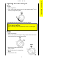
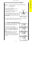
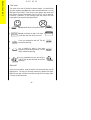
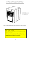
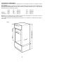
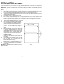
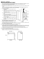
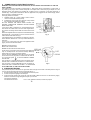
Model EOG9330
n
EOG 9330
c
oit
Introduction
t
This gas appliance has been designed and manufactured to all the
necessary British Standards. It also carries the C.E. mark. The
appliance complies with European Council Directive 90/396/EEC.
It is important that you understand how to use and care for the appliance
properly before you use it for the first time.
We have written this booklet with your safety in mind. Read the booklet
thoroughly before you use the appliance. Keep the booklet in a safe
place so that anyone who uses the appliance can read it. Pass the
booklet on with the appliance if you sell it to someone else.
nI
or
d
u
For your safety
This appliance is not intended to be operated by means of an
external timer or separate remote control system.
The appliance is designed for domestic use to cook food. You
must not use it for any other purpose. It is not designed for
commercial use.
Keep children, babies and toddlers away from the appliance at all
times.
The installation instructions that came with the appliance tell you
how and where it can be fitted. If the appliance is already
installed you must make sure that all instructions have been
followed. If you are in any doubt ask a registered person. More
details on installation on page 4.
We have included several drawings to show the right and wrong way
of doing things.
The right way will have a smiling face by it.
A sad face shows something is wrong.
RATING PLATE
This is situated on the lower front frame of the appliance and can be
seen upon opening the door. Alternatively the rating plate may also be
found on the back or top of some models (Where applicable). Do not
remove the rating plate from the appliance at this may invalidate
the guarantee.
2
Contents
Contents
EOG 9330
Page
Installing the appliance
4
General information
5
The cooling fan for the controls
5
Ignition
6
Lighting the oven and grill
7
Oven light
8
The grill
9
The grill pan and handle
11
The oven
13
Baking trays and dishes
15
Oven cooking charts
16
Slow cooking
19
The electronic timer
21
Care and cleaning
23
What is wrong and why?
27
Replacing an oven light bulb
29
Servicing
30
Installation Instructions
32
Technical Data
33
Safety requirements/ventilation
34
Location of appliance
35
Installation
36
Testing
38
Guarantee conditions
42
3
Installation
EOG 9330
Installing the oven
For your safety
This appliance must be installed and serviced by a competent
person as stated in the Gas Safety (Installation & Use)
regulations current edition and IEE Wiring Regulations.
It is important that the appliance is suitable for your gas supply.
Your installer should check the rating plate.
Cabinet Dimensions
This appliance must be fitted into a cabinet with a suitable sized
aperture.
Minimum aperture height
Minimum aperture width
874mm
560mm
Minimum aperture depth
560mm
Location
For your safety
The use of a gas cooking appliance results in the production of
heat and moisture in the room in which it is installed. Ensure that
the kitchen is well ventilated: keep natural ventilation holes open
or install a mechanical ventilation device (mechanical extractor
hood).
Prolonged intensive use of the appliance may call for additional
ventilation, for example opening of a window, or more effective
ventilation, for example increasing the level of mechanical
ventilation where present.
For further details see page 34.
4
General information
To get the best results from your new appliance please read these
instructions carefully.
You should pay particular attention to cooking times and gas mark
settings as these may differ from your previous appliance. You may find
it necessary to adjust these until you are more familiar with the
appliance.
For your safety
Do not block any of the oven vents.
Never line any part of the oven with foil.
Do not let items which can catch fire or electric mains leads such
as kettle flexes trail over any part of the oven.
Appliance housing units vary widely in construction and finish. To
avoid possible damage to the housing unit, you must not leave cabinet
doors or flaps above the appliance open or partially open when you use
the grill or appliance. If you have a storage area above your appliance it
will become warm when you use the appliance. Do not store perishable
foods in the storage area above the appliance.
The cooling fan for the controls
Your appliance has a cooling fan. The cooling fan will start to work as
soon as you light the grill or appliance. You will be able to hear the fan
when it is working.
The cooling fan may continue to work after you have turned off the
appliance or grill. It will switch itself on and off until the appliance has
cooled down.
If you want to turn off the electrical supply to the appliance, you
should not do so until the cooling fan has stopped working.
For your safety
When you are using the grill or oven warm air will exhaust from
the grill cavity and the vents below the control panel.
Take care not to stand too close to the oven or grill while in use.
5
General information
EOG 9330
General information
EOG 9330
Ignition
The grill and oven burners light automatically when you turn on the
control. If, for any reason either of the burners go out, the spark ignition
will automatically relight it.
Please note:
You can only use the grill with the door fully or partially open. You
cannot use the grill when the door is closed.
You cannot use the oven or grill in the event of a power failure.
Connecting to the electricity supply
For your safety
This appliance must be earthed and protected by a 3 amp fuse.
The plug supplied with the appliance can be fitted directly to a suitable
three pin earthed socket. Ensure the plug is accessible to the user.
If you have to change the fuse replace it with a 3 amp fuse which has
been ASTA approved to BS 1362.
Do not use the plug until you have put the fuse cover back on. If the
fuse cover is lost you can get a replacement from an electrical retailer.
The correct replacement can be identified by marking or colour coding.
If you cut the plug off dispose of it safely as it will be a shock hazard
if it is inserted into a 13 amp socket elsewhere in the house.
If the ignition system doesn't work there may be a fault with the
electrical supply. First, check the socket by trying out another piece of
electrical equipment in it, if that works correctly renew the fuse in the
plug.
If the fuse keeps failing there is a fault in the appliance which must
be put right. Do not use a fuse with a rating higher than 3 amps. Do not
carry out other electrical work. Unplug the appliance and tell your
installer.
6
Lighting the oven and grill
Grill
To light:
1 Open the grill door.
2 Push in the control knob and turn it to the highest setting. This is
shown by a large flame symbol.
3 Leave the grill door open when you you are using the grill.
For your safety
Never cover the grill pan or grid with foil as this can lead to grill
fires.
Oven
To light:
1 Open the oven door.
2 Push in the control knob and turn it to gas mark 9. When the burner
has lit there will only be small flames at first.
3 Now turn the control knob to the gas
mark you want.
4 Wait until the burner is showing large
flames.
5 Close the oven door.
7
Lighting the oven and grill
EOG 9330
Lighting the oven and grill
EOG 9330
To turn off any burner
1 Push in the control knob and turn it to the off position.
This is shown by a large dot.
For your safety
When you are lighting any burner check that it has lit before you
leave the appliance.
When you are turning off a burner do not leave the appliance
until the flame has gone out.
Oven light
The main oven light will come on when the oven burner is alight. If you
need to replace the oven light bulb, follow the instructions given on page
29.
8
The grill
We suggest that you run the grill without food for approximately 5 - 10
minutes to burn off any residue from the surface. During this period an
odour may be emitted, it is therefore advisable to open a window for
ventilation.
Heat control
The grill gives variable heat settings.
The control knob turns to the left from
'OFF' to 'HIGH' and then to 'LOW'. The high
setting should be used for fast cooking such
as toast. Use a lower setting to cook thicker
foods such as chicken after it has been
browned on the high setting.
You should remember to turn the food
regularly.
You should not use the grill to keep food warm as it will continue to
cook the food.
The grill pan should be used on the shelf without the metal plate
underneath it. The shelf can be positioned in any of the runner positions.
You can reverse the grill pan grid to suit different types of food.
If you close the door whilst the grill burner is lit, it will go out and you
will hear a continuous 'sparking'. The burner will automatically re-light
when you open the door.
For your safety
You must keep the grill door open when the grill burner is lit.
Accessible parts may be hot when the grill is used. Young
children should be kept away.
Never cover the grill pan or grid with foil as this can lead to grill
fires.
9
The grill
EOG 9330
The grill
EOG 9330
Cooking positions
There is only one position for the grill shelf
(Position 2). Positions are counted from the
top downwards.
Most food should be cooked on the grid
in the grill pan. You can turn the grid over to
suit different thicknesses of food.
You can place some dishes straight on
the grill shelf. This is useful when you are
browning the top of food such as cauliflower
cheese.
Preheating
You don't usually need to preheat the grill. You may wish to preheat it for
a couple of minutes when you are cooking steak or browning food.
Positioning food on the grid
Place food such as toast, tea-cakes and
muffins towards the centre of the grid. If you
put food outside this area it may require
rotating during cooking.
Place food which needs a more gentle
heat, such as tomatoes or mushrooms
towards the edge of the grid.
Arrange meat, meat products and fish to
suit their thickness and how you like them
cooked.
10
The grill pan and handle
The grill pan is supplied with a removable handle.
To attach the handle, place the wirework under the cut out in the pan so
that the metal plate hooks over the top of the grill pan.
Slide the handle to the left and over the central bump on the grill pan.
Ensure the handle is correctly located. It is not necessary to
remove the grill pan handle during grilling.
Place the grill pan on the shelf so that the pan is positioned centrally
beneath the grill.
To remove the handle, slide the handle to the right and lift the handle
away from the cut out on the grill pan.
Note
If you require an additional handle for your grill pan, this can be ordered
from your local Service Force Centre by quoting part number
311479800\6.
11
The grill
EOG 9330
The grill
EOG 9330
To check the progress of the food when using the grill you should
withdraw the grill pan on the shelf to attend to food. After removing the
grill pan you can rest it on a heat resistant work surface if you need to.
Plate warming
You can use the grill compartment to warm plates while the oven is on.
Do not place plates to warm under the grill when it is on as this may
damage the plates.
12
The oven
For your safety
Never leave the appliance unattended when the oven door is
open.
Before you use the oven you should wipe it out with a damp cloth. This
will remove any dust.
We suggest that you run the oven without food for 10 - 15 minutes at
Gas mark 7 to burn off any residue from the surface. During this period
an odour may be emitted, it is therefore advisable to open a window for
ventilation.
Heat zones
There are zones of heat within the oven. The
temperature in the middle is the gas mark
you have chosen.
The top of the oven is slightly hotter and
the lower shelf slightly cooler. The base of
the oven is quite a lot cooler. You can make
use of these heat zones when you are
cooking
foods
requiring
different
temperatures all at the same time.
If you are cooking more than one tray of similar items, for example
cakes or biscuits, swap the trays around during cooking. Or you could
remove the top tray when the food is cooked and move the lower tray to
the higher shelf to finish cooking.
Preheating
You do not need to preheat the oven for casseroling and so on.
Preheat the oven for baking or when you are cooking sensitive food
such as Yorkshire puddings, soufflés and yeast mixtures.
When you are cooking or reheating frozen or chilled food read the
instructions on the packaging.
When you need to preheat the oven, we recommend you do so for
20 minutes.
13
The oven
EOG 9330
The oven
EOG 9330
Oven shelves
The two oven shelves can be slotted into place in any of five positions.
For safety the shelves will only pull out so far. If you want to remove a
shelf completely, pull it forward as far as it will go, raise the front edge
and lift it out. To put the shelf into a different position, keep the front
edge raised, slot the shelf onto the runner, lower the front edge and slide
the shelf in.
The shelf positions are counted from the
top downwards and recommended shelf
positions are given in the cooking charts on
pages 16, 17 and 18. When cooking always
try to leave at least one runner position
between shelves to allow the heat to circulate
properly.
The recommended shelf positions given in the oven cooking charts give
the best results.
When you only need to use one shelf you can store the other shelf
above or below the one you are using where there is more space.
Use the shelf with the metal plate in a higher runner position when
cooking on two levels.
14
Baking trays and dishes
For your safety
Never place cooking dishes, trays
and so on over the oven burner.
This will damage the oven as well
as the ovenware and possibly the
cabinet underneath the oven.
Leave a gap of 13mm (½")
between
thebetween
sides of all
Leave
a gapallofdishes
13mmand
(½")
theand
oventhe
so sides
the heat
can circulate
dishes
of the
oven so the
heat properly.
can circulate properly.
Do not push dishes too far back
Do not
back as food
as push
food dishes
will burntooif itfaroverhangs
the will
burnburner
if it overhangs
the
burner
flames.
flames.
For the best results we recommend that you use a baking tray which is
310mm (12") square. If you use a tray or tin which is larger than this,
you may need to turn it around during cooking.
Place single dishes on the centre of the shelf. You may need to turn
large items around during cooking.
Roasting
For best results we recommend open roasting using minimal fat or oil to
prevent splashing.
It is not necessary to cover meat or poultry or wrap food in foil when
roasting as this restricts the circulation of heat and will lead to extended
cooktimes.
If you are using a roasting bag or cover chicken breast with foil, be
prepared to allow an extra 10 - 15 minutes for each 1/2kg (1lb).
When cooking large items such as turkeys, the use of foil may be
required to prevent the breast becoming dry before the rest of the bird is
fully cooked.
Condensation
Condensation may form on the oven. This is quite normal and nothing to
worry about. The condensation forms when heat and moisture are
present, for example during cooking. Whenever possible try to make
sure that food which contains a lot of moisture for example casseroles
are covered. If you do notice any condensation, wipe it up straight away.
15
The oven
EOG 9330
Food
Roasting meat:
16
Pork and Veal
Lamb
Beef
Shelf
position
4*
Approximate
cooking time
Rare:
20 mins. per ½kg (1 lb) and 30 mins.
Medium:
25 mins. per ½kg (1 lb) and 25 mins.
Well Done:
30 mins. per ½kg (1 lb) and 30 mins.
5
4*
Medium:
25 mins. per ½kg (1 lb) and 25 mins.
Well Done:
30 mins. per ½kg (1 lb) and 30 mins.
5
4*
Medium:
30 mins. per ½kg (1 lb) and 30 mins.
Well Done:
35 mins. per ½kg (1 lb) and 35 mins.
Thoroughly thaw frozen joints before cooking them.
* Recommended position for shelf with metal plate.
Gas
mark
5
These instructions are for cooking in the oven after it has been pre-heated for 20 minutes.
When you are using both shelves, use the shelf with the metal plate in the higher position.
If you are cooking more than one tray of similar items, for example cakes or biscuits, swap the trays around during cooking or you
can take the top tray out of the oven when the food is cooked and move the lower tray to the higher shelf to finish cooking.
Always leave at least one shelf position between shelves to allow heat to circulate.
The recommended shelf positions give the best results.
Put the dishes in the centre of the shelf.
You can change the gas marks and cooking times to suit your own tastes.
It is important to check that food is piping hot before serving.
Oven cooking chart
Oven cooking chart
EOG 9330
17
Oven cooking chart
Gas
Shelf
Approximate
mark
position cooking time
4*
20 mins. per ½ kg (1 lb) and 20 mins.
Poultry:
Chicken
5
25 mins. per ½ kg (1 lb) and 25 mins.
5
Turkey below 4.5kg (10lbs) 4
5
15 mins. per ½ kg (1 lb) and 15 mins.
over 4.5kg (10 lbs) 4
25 mins. per ½ kg (1 lb)
4*
Duck and duckling
5
Stuffed poultry
Cook as above but calculate weight including stuffing
Thoroughly thaw frozen joints before cooking them.
The times given above are for open roasting in a preheated oven. If you cover the food with foil or a lid allow an extra 10 - 15
minutes for each ½kg (1lb).
Yorkshire pudding - large
7
2*
25-30 mins.
- individual
7
2*
15-25 mins.
4-5 hours.
5*
Cakes:
Christmas cake 230mm (9") 2
2¼ hours.
5*
Rich fruit cake 180mm (7") 2
2½-2¾ hours.
5*
205mm (8") 2
60 mins.
5*
Madeira,
180mm (7") 4
15-25 mins.
1* & 4
5
Small cakes
10-20 mins.
1* & 4
7
Scones
Victoria sandwich
20-30 mins.
2* & 4
4
180mm (7")
20-35 mins.
2* & 4
4
205mm (8")
* Recommended position for shelf with metal plate.
Food
EOG 9330
Plate tart (shortcrust)
Fruit pie (shortcrust)
Mince pies (flan pastry)
Profiteroles (choux pastry)
Approximate
cooking time
25-35 mins.
25-35 mins.
20-25 mins.
25-30 mins.
Shelf
Position
2*
2*
1* & 4
2
Gas
Mark
6
6
5
4
18
Bread 0.45kg (1 lb loaves)
0.90kg (2 lb loaves)
Rolls and buns
Yeast mixtures:
8
8
8
2
4
3
3*
3*
2*
3
4*
2
30-40 mins.
30-40 mins.
15-20 mins.
1½-2 hrs.
45-60 mins.
50-60 mins.
*Recommended position for shelf with metal plate.
Note: You must soak dried beans then boil them in an open pan for 15 minutes before you add them to any dish.
Milk puddings
Baked sponge pudding
Baked custard
Puddings:
To help pastry brown on the underside cook on a metal plate, or if plates are flat and have no rim underneath, place on baking
tray to cook.
Pastries:
Food
Oven cooking chart
EOG 9330
Slow cooking
The slow cook setting gives a very low heat in the oven. It is particularly
useful when you are cooking soups, stews and casseroles because the
long slow cooking will make cheaper, tougher cuts of meat more tender.
You need to cook food at gas mark 6 for 30 minutes before you turn
the oven down to the slow cook setting. This makes sure that the
temperature of the food gets hot enough to start the food cooking.
Some foods such as pastry and biscuits are not suitable for slow
cooking because the temperature is too low.
Cover all food during cooking to prevent it from drying out. You can
uncover food for the last half hour if it is normally served golden brown.
Food preparation-slow cooking
Joints of meat and poultry
l
l
l
l
l
l
l
l
l
l
Do not cook meat joints over 2.7kg (6lb).
Do not cook poultry over 2kg (4lb 8oz).
Cook on the middle shelf of the oven or above.
Cook stuffing separately.
Cook for at least 6 hours.
Only cook joints of pork if you can make sure, by using a meat
thermometer, that the temperature inside the joint is at least 88oC.
For good air circulation always stand joints on a rack in a roasting tin
or casserole
Thaw all frozen meat and poultry before cooking.
Prime cuts of meat do not benefit from slow cooking.
Remove excess fat and skin unless it is browned first.
19
Slow cooking
EOG 9330
Slow cooking
EOG 9330
Soups, casseroles and stews
l
l
l
Do not cook casseroles over 2.7kg (6lb).
Cook in the middle of the oven or above.
Cover food with a tight fitting lid or tin foil.
Vegetables
l
l
l
l
l
l
Cut into small pieces.
Dried beans must be pre-soaked then boiled in an open pan for 15
minutes before adding to any dish.
To prevent vegetables from discolouring, add lemon juice.
Place vegetables under meat in casseroles.
Cover food with a tight fitting lid or tin foil.
Cook for 30 minutes at gas mark 6, then reduce to the slow cook
setting.
Milk puddings
l
l
l
Cover the cereal with boiling water and allow to stand for 30 minutes.
Drain and make the pudding in the usual way.
Cook for 30 minutes at gas mark 6, then reduce to the slow cook
setting.
General points for slow cooking
Frozen foods
Thaw thoroughly before cooking.
Thickening
Toss meat in flour for casseroles. Alternatively blend cornflour with
water and add it at the end of cooking.
Flavouring
Flavours are retained because there is little evaporation. Adjust at the
end of the cooking time.
Liquid
Reduce normal liquid quantities slightly as there is little evaporation
during cooking time.
Milk and milk products, for example cream
Add these towards the end of cooking to prevent them from curdling.
Reheating
Cool left over food quickly and then put it in the fridge.
Do not reheat food using the slow cook setting. Reheat food in the usual
way or in a microwave.
Only reheat food once.
20
THE ELECTRONIC MINUTE MINDER
-
Button 1 = ( ) Decrease control and minute minder setting button
Button 2 = (+) Increase control
( ) Bell Symbol
The electronic minute minder can also be
used to show the time of day.
Bell symbol
Please note that this is a 24 hour clock, for
example 2pm is shown as 1400.
In the following pages we explain how to use
the minute minder and set the time of day.
Read through them until you're familiar with
the procedure.
button 1
button 2
If the oven is switched off on the wall or there is a loss of power, the
clock will stop and you will not be able to use the oven.
1. TO SET THE TIME OF DAY
When the electricity supply is first switched
ON, the display will flash 0.00 See Fig1.
Fig 1.
Press buttons (1) and (2) together.
Release the buttons, 0.00 will appear in the
display as Fig 2. Within 5 seconds press
button 2. 12.00 will show in the display as
Fig 3.
Within 5 seconds press and hold either
button (1) to decrease or button (2) to
increase the time until the correct time of day
on the 24 hour clock is reached, eg 14.30
See Fig 4.
Fig 2.
Fig 3.
Fig 4.
21
The electronic timer
EOG 9330
The electronic timer
EOG 9330
2. TO USE THE MINUTE MINDER
The minute minder gives an audible reminder
at the end of any period of cooking up to 23
hours and 59 minutes.
Fig 5.
To set press button (1) and the display will
read 0.00, See Fig 5.
Release button (1) and press and hold
button (2). The display will count up in one
minute intervals until the interval to be timed
is reached, eg 30 minutes, See Fig 6. If
necessary press and hold button (1) to
achieve the correct time interval.
The bell symbol will show in the display.
Fig 6.
Fig 7.
The minute minder will begin to count down
once set. The time of day will show in the
display. To show the remainder of the cook
time press button (1).
At the end of the time period an audible
signal will sound for up to 2 minutes. The
bell symbol will flash and the time of day will
show in the display. See fig 7.
To stop the sound press button (1). The bell
symbol will go out and show the time of day
eg 15.00. See Fig 8.
Fig 8.
Fig 9.
3. TO CANCEL THE MINUTE MINDER
If you change your mind and want to cancel
the minute minder.
Press and release button (1). See Fig 9.
Press and hold button (1) and the display will
count down in one minute intervals to 0.00.
See fig 10. Release button (1). After a few
seconds the time of day will show in the
display. See Fig 11
22
Fig 10.
Fig 11.
Care and cleaning
For your safety
For hygiene and safety reasons you must keep this gas
appliance clean. A build up of fat or other foodstuff could cause a
fire.
Try to mop up spills and splashes as soon as they happen.
Do not use any polishes, caustic cleaners, abrasives, washing soda or
soap powder except those recommended in this booklet.
Please note: If we recommend you use hot
soapy water we mean hot water with washing
up liquid in it and not any other cleaning
appliance.
If you own a dishwasher please read the
operating instructions for the machine before
you wash any part of your appliance in it.
Clean your appliance regularly using a cloth that has been wrung out
in hot soapy water. Rinse and polish it dry using a soft cloth. Stainless
Steel cream cleaners are abrasive and should be avoided as they
may damage the surface finish.
When you remove parts of your appliance for cleaning do not
plunge them into water whilst they are very hot as this may damage the
finish of the parts.
Cleaning stainless steel handles and control
knobs (Where applicable)
Do not remove the control knobs from the appliance as damage
may occur. It is strongly recommended that only hot soapy water and a
soft cloth is used for cleaning the door handles and control knobs. ANY
OTHER CLEANING MATERIALS DULL THE FINISH. Care should be
taken when cleaning, to ensure that all cleaning products are wiped from
the control knobs immediately.
The grill
Clean the grill compartment, the shelf, grill pan and handle, grid ,and the
inner grill door while they are still slightly warm. This way you can easily
remove any splashes and spills. Clean them with a cloth that has been
wrung out in soapy water. You may use mild abrasives such as 'Cif'. For
more stubborn marks you may occasionally need to use a soap filled
pad such as 'Brillo'.
23
Care and cleaning
EOG 9330
Care and cleaning
EOG 9330
The oven
The inside of the oven is finished in vitreous enamel. You should clean
the oven regularly using hot soapy water and mild abrasives or a soap
filled pad such as 'Brillo'. If you use any oven cleaners they must have
the Vitreous Enamel Development Council (VEDC) seal of approval.
Follow the instructions on the cleaning agent and protect the oven
burner with foil to prevent it becoming blocked.
Do not overfill dishes or they will boil over.
Do not use dishes too high in the oven. If
you do they may stick to the oven roof.
Cover your roasting tins with foil. This will
prevent fat splashing.
Use a roasting tin which is just large
enough for the meat and potatoes. This will
help to reduce fat splashing.
Dry any vegetables that you are going to
roast. If they are wet there will be more fat
splashing.
General
Clean the oven shelves, meat tin and the oven door while they are still
slightly warm. This way you can easily remove any splashes and spills.
Wipe the base with a cloth that has been wrung out in hot soapy water.
You may use mild abrasives.
24
Cleaning between the outer and inner
door glass
You can remove the glass from the oven and grill doors if you need to.
The grill door is fitted with a trim. You must note the correct position of
the trim when you remove the grill door glass.
To remove the outer glass
1 Open the door so you can get at the two cross head screws on the
top of the door.
2 Loosen these two screws using a pozidrive screwdriver.
Please note that the door
glass on your product may
differ in type and shape from
that shown in the diagram.
3 You should hold the door glass securely in place with one hand,
whilst removing the screws completely, with the other hand. If you do
not do this, the door glass could fall forward. Still holding the door
glass, remove the trim from the top of the grill door.
Note the correct position of the grill door trim. The oven door does
not have a trim.
4 Using both hands, gently tilt the top of the door glass towards you.
Lift it slightly to disengage the locators at the bottom of the door.
5 Clean the outer and inner glass using hot soapy water and mild
abrasives such as 'Cif'.
6 Replace the glass by holding it in both hands and gently placing the
locators into the holes of the brackets at the bottom of the door. Push
the top of the glass towards the door, and make sure the screw
location holes line up. Replace the trim on top of the grill door
making sure that it is correctly positioned. You can check this by
looking through the air gap on the top of the door and checking that
the screw location holes line up.
7 Hold the glass in place with one hand and replace the cross head
screws into the location holes, with the other hand.
8 Tighten the screws using a pozidrive screwdriver. Close the door.
25
Care and cleaning
EOG 9330
Care and cleaning
EOG 9330
Cleaning The Door Glass
To prevent damaging or weakening the door glass panels
avoid the use of the following:
Household detergents and bleaches
Impregnated pads unsuitable for non-stick saucepans
Brillo/Ajax pads or steel wool pads
Chemical oven pads or aerosols
Rust removers
Bath/Sink stain removers
If the door glass panel becomes chipped or has deep
scratches the glass will be weakened and must be replaced
to prevent the possibility of the panel shattering. Please
contact your local Service Force Centre who will be
pleased to advise further.
Under no circumstances should the door assembly be
detacted from the appliance for cleaning. Plase refer to the
cleaning instructions.
26
What is wrong and why?
We strongly recommend that you carry out the following checks on your
appliance before calling a Service Engineer.
Problem
The oven or grill will not light.
Check
l
l
l
l
Check that the appliance is switched on at the wall.
Check that the timer is set to 'manual' (See page 21).
Check that there has not been a power failure. If the electricity
supply has been interrupted or you have switched the appliance off
at the wall the grill may have cut out before the cooling fan has
cooled the oven down. Switch the appliance on at the wall until the
cooling fan has cooled it down.
Check that there is not a problem with your gas supply. You can do
this by making sure that other gas appliances such as your central
heating or gas fire are working.
Problem
Food is cooking too quickly or too slowly.
Check
l
Check that you are using the recommended gas marks and shelf
positions. See pages 16, 17 and 18. Be prepared to adjust the gas
mark up or down to achieve the results you want.
Problem
The oven is not cooking evenly.
Check
l
l
l
l
Check that the appliance is installed properly and is level.
Check you are using the recommended temperatures and shelf
positions.
If you are using a tin or tray which is larger than the one we
recommend, be prepared to turn it round during cooking
If you are cooking a large item be prepared to turn it round during
cooking.
27
What is wrong and why?
EOG 9330
What is wrong and why?
EOG 9330
Problem
Having difficulty cleaning any part of the appliance.
Check
l
Check that you are following the instructions for care and cleaning
(See page 23).
Problem
The oven lights do not work.
Check
l
If you have had your appliance for some time you may need to
replace an oven light bulb. (See page 29).
Problem
The timer does not work.
Check
l
Check that the timer instructions are being closely followed.
(See page 21).
Problem
The oven or grill burner flame is unstable/noisy.
Check
l
Check that the burner flames stabilise after a few minutes. It may be
that the appliance needs to adjust to room temperature.
28
Replacing an oven light bulb
You need a 25 Watt small Edison screw with a temperature rating of
T300.
Make sure the oven is cool before you replace a bulb.
Unplug the appliance.
Open the oven door and remove the oven shelves.
Pull the glass bulb cover towards you and then pull it off.
Unscrew the bulb by turning it to the left.
Fit a new bulb and then replace the glass bulb cover.
Replace the oven shelves.
Plug the appliance back into the electricity supply.
Re-set the time of day.
The oven light bulb is not covered by the manufacturers guarantee.
l
l
l
l
l
l
l
l
l
29
Replacing an oven light bulb
EOG 9330
Servicing
EOG 9330
Service and spare parts
In the event of your appliance requiring service, or if you wish to
purchase spare parts please contact your local Service Force Centre
by telephoning:-
08705 929929
Your telephone call will be automatically routed to the Service Force
Centre covering your post code area.
For the address of your local Service Force Centre and further
information about Service Force, please visit the website at
www.serviceforce.co.uk
Before you call an engineer check through the information under the
heading 'What is wrong and why?'
In-guarantee customers should ensure that the checks
under the heading 'What is wrong and why?' have been
made as the engineer will make a charge if the fault is not a
mechanical or electrical breakdown.
Please note that it is necessary to provide proof of purchase
for any in-guarantee service calls.
When you report a problem try to describe the nature of the fault.
Always give your appliance's full name, model and serial number.
Make a note of this information in this space:
Name:
Model Number:
Serial Number:
P.N.C. Number:
30
For your safety
Maintenance must only be carried out by a competent /qualified
person. Do not try to repair or alter/modify the appliance
yourself as this could be dangerous.
We recommend that your appliance has an annual gas safety
check carried out by our approved service organisation.
Customer Care Department
For general enquiries concerning your Electrolux appliance or further
information on products, you are invited to contact our Customer Care
Department by letter or telephone as follows or visit our website at
www.electrolux.co.uk
Customer Care Department
Electrolux
55-77 High Street
Slough
Berkshire
SL1 1DZ
Tel: 08705 950950 *
* calls to this number may be recorded for training purposes.
For Customer Service in Ireland please contact us at the address below:
Electrolux Group (IrI) Ltd
Long Mile Road
Dublin 12
Republic of Ireland
Tel: +353 (0)1 4090753
Email: [email protected]
The Gas Consumers' Council
The Gas Consumers' Council (GCC) is an independent organisation
which protects the interests of gas users.
If you need advice, you will find the telephone number in your local
telephone directory under Gas.
31
Servicing
EOG 9330
INSTALLATION INSTRUCTIONS
Serial number on front
frame. Rating plate on
rear of electrics panel
Please note that the handle may differ in type and shape from that shown in the diagram.
For your safety
Where applicable Natural Gas and L.P. Gas versions of this
appliance are available.
Check that this model is suitable for the type of supply available.
In the interest of safety this appliance must be installed and/or
serviced by a competent person, as stated in the Gas Safety
(Installation and Use) Regulations Current Editions.
32
TECHNICAL DATA
DIMENSIONS
Overall
Flexible Gas Pipe
Minimum Cabinet
Solid Gas Pipe
Minimum Cabinet
Maximum Cabinet
Weight of Appliance
Minimum Clearance top of
Appliance to Roof of Cabinet
Height
885
Width
595
Depth
595
874
560
575
874
879
52.0kg
560
570
560
N/A
3mm (1/8")
CONNECTIONS
Gas
Flexible Hose
Solid Pipe
Electrical
GRILL
Burner
Heat Input
Injector Marking
Rear top right hand side of appliance
Rc½ (½" B.S.P. Female).
Right hand side of appliance above grill
Behind control panel Rc¼ (¼" B.S.P. Female)
Rear of appliance at bottom left hand side 240V a.c. 50Hz
Mains 3 core cable and moulded plug fused to 3 amp.
Natural Gas
Steel tubular burner with expanded metal frets.
2.8kW (9556 Btu/h)
123
OVEN
L.P.Gas
2.8kW (201 g/h)
089
Natural Gas
L.P.Gas
Burner
Sheet metal construction mounted transversely at rear of oven.
Heat Input
2.4kW (8189 btu/h)
2.4kW (172 g/h)
Injector Marking
108
078
Thermostat By-Pass Marking
74
79
GAS CATEGORY
COUNTRIES OF DESTINATION
CAT. I2H
GB, IE
CAT. I3+
GB, IE
33
IMPORTANT - SAFETY REQUIREMENTS
This appliance must be installed in accordance with the Gas Safety (Installation and Use) Regulations Current
Editions and the I.E.E Wiring Regulations. Detailed recommendations are contained in the following British
Standard Codes of Practice - BS.6172, BS.5440: Part 2 and BS.6891. All British Standards must be 'Current
Editions'.
PROVISION FOR VENTILATION
This appliance is not connected to a combustion products evacuation device. It shall be installed and
connected in accordance with the current installation regulations. Particular attention shall be given to the
relevant requirements regarding ventilation.
The room containing the appliance should have an air supply in accordance with BS. 5440: Part 2 Current
Edition. All rooms require an openable window or equivalent and some rooms will require a permanent vent
as well. For room volumes up to 5m³ an air vent of 100cm² is required: for room volumes between 5m³ and
10m³ an air vent of 50cm² is required. If the room has a door that opens directly to the outside, no air vent is
required. For room volumes that exceed 11m³ no air vent is required. If there are other fuel burning
appliances in the same room, BS.5440: Part 2 Current Edition should be consulted to determine the requisite
air vent requirements.
Prolonged intensive use of the appliance may call for additional ventilation, for example opening a window, or
more effective ventilation, for example increasing the level of mechanical ventilation where present.
34
LOCATION OF APPLIANCE
This appliance must not be installed in a bed-sitting room of volume less than 20m³ or in a bathroom, shower
room or garage.
It is essential that there is a minimum clearance of 3mm between the top surface of the appliance and
the inside top of the cabinet. The unit must be fitted into a cabinet conforming to Fig. 1. The following
internal dimensions are particularly important.
Solid Pipe
Flexible Pipe
Height
Width
Depth
Depth
874............Minimum
560............Minimum
560........... Minimum
575............Minimum
879..........Maximum
570..........Maximum
N/A.........Maximum
N/A.........Maximum
NOTE: Where a cupboard door with a handle is situated above the appliance, we recommend a minimum
clearance gap of 5mm between fascia top trim and door.
L.P.G. cookers MUST NOT be installed below ground level, i.e. in a basement, or aboard any boat, yacht or
other vessel.
Fig.1
2000 recommended
560
m
570 in
max
874 min
879 max
600
min
min
560
35
INSTALLATION
Flexible Pipe Installation.
FITTING THE APPLIANCE AND CABINET
It is recommended that a 3/8" 1100mm long angle bayonet flexible hose (B.F.S.) and a ½" straight socket
(B.F.S.) be used for the installation. However any approved hose of the correct length can be used.
IMPORTANT: Flexible tubing used must comply with BS 669 current editions. L.P.G. flexible connections
must be of a type suitable for L.P.G. and capable of operation up to 50mbar and carry a red stripe, band or
label.
NOTE: Only liquid sealants can be used in threaded gas connections. Do not use P.T.F.E. tape.
1
Make suitable arrangements for gas and electric supplies into the installation site. Preferably a junction
box or a 3 pin earthed socket should be situated at the back of the cabinet below the oven.
2
The electrical connection to the appliance is at the rear bottom right hand side; the junction box or socket
should be positioned accordingly.
3
Fit the cabinet as Fig.1, make sure that it is level.
4
When unpacking the appliance keep it on it's polystyrene base until it is put into the cabinet to avoid
damage.
NOTE: It is imperative that the appliance is left in the base to protect both the appliance and the floor.
Do not allow young children to play with any part of the packaging.
5
Remove the fascia panel (See section A on page 39).
6
If the gas supply bayonet and wall fixing bracket
are to be located behind the appliance it must be
located in the shaded area as indicated in Fig.3.
7
Connect flexible hose to the gas inlet supply block
see Fig.3. The hose should be long enough to
allow the appliance to be withdrawn from the
cabinet.
8
Position the appliance in front of the cabinet and
run the supply cable (See Section 2) through the
cabinet and connect to the junction box or socket.
Ensure that the supply is isolated at this stage.
Connect flexible hose to the bayonet connector.
N.B. Two people will be required to carry out
the lifting procedure.
Warning: Do not attempt to lift this appliance by
the handles.
9
Lift the appliance into the cabinet making sure the
hose and cable are not trapped. Push the
appliance as far back as it will go.
10 Centralise and fix the appliance using the six wood
screws provided, in the position indicated in Fig.2.
11 Carry out a gas tightness test after connecting to
the gas supply.
Fig.2
NOTE: Check gas supply pressure before fitting fascia
(See SECTION 3).
36
INSTALLATION Solid Pipe Installation
FITTING THE APPLIANCE AND CABINET.
1
2
3
680
4
Make suitable arrangements for gas and electrical supplies into the installation site. Preferably a junction
box or a 3 pin earthed socket should be situated at the back of the cabinet below the oven.
Fit cabinet as Fig. 1, making sure that it is level.
When unpacking the appliance keep it on it's polystyrene base until it is put into the cabinet to avoid
damage.
NOTE: It is imperative that the appliance is left in the base to protect both the appliance and the floor.
Do not allow young children to play with any part of the packaging.
GAS INLET SUPPLY BLOCK
Solid gas pipe installation:
i)
Remove the fascia control panel (See section A
on page 39).
ii) Slacken and remove the union nut on the gas
supply elbow on the right hand side of the
control panel. See Fig.7.
iii) Remove the two screws on the gas inlet block
Fig.3.
iv) Withdraw the gas inlet block and pipe assembly
from the back of the appliance
v) Remove the union elbow from the inlet block
and pipe assembly. The elbow will be required
0
28
in the final installation.
vi)
6
7
8
9
10
SIDE VIEW
FRONT VIEW
75
225
mm
Fig.4
795
5
The union elbow should be connected to the
gas supply pipe via a standard ¼"B.S.P. straight
120
connector.
Install the gas supply pipe on site complete with the
Fig.3
union elbow (See Fig.4). Note the orientation of the
elbow, the connection must be upwards.
120
Position the appliance in front of the cabinet and run
the supply cable (See Section 2) through the cabinet and connect to the junction box or socket. Ensure
that the supply is isolated at this stage.
N.B. Two people will be required to carry out the lifting procedure.
Warning: Do not attempt to lift this appliance by the handles.
Lift the appliance into the cabinet making sure the gas supply pipe enters the duct in the rear of the
appliance and the cable is not trapped by the appliance. Push the appliance as far back as it will go.
Ensure the supply pipe comes through the control panel and pull through any slack cable.
Centralise and fix the appliance to the cabinet using six wood screws in the position indicated in Fig.2.
Tighten the union nut into the supply elbow.
Carry out a gas tightness test after connecting to the gas supply.
NOTE: Check supply pressure before fitting fascia (See Section 3).
37
2. CONNECTION TO ELECTRICITY SUPPLY
WARNING: THIS APPLIANCE MUST BE EARTHED, DO NOT EARTH THIS APPLIANCE TO THE GAS
SUPPLY PIPING.
This appliance must be connected to a 230V-240V a.c. 50Hz supply which incorporates a 3 ampere fuse. If
any other type of plug is used it should incorporate a 5 ampere fuse in either the plug or adapter or at the
distribution board. The appliance is supplied with 2 meters (6.5 ft) of 5 ampere 3 core cable, fitted with a
moulded plug. If this proves insufficient to allow the appliance to be plugged into the nearest supply socket.
Ensure the plug is accesible to the user.
The supply cable can be either:i)
Replaced totally by a longer cable at least 0.75mm²
nominal cross sectional area (24/0.2).
ii) Extended by using a B.E.A.B. approved 3-way sealed
flex connector with integral flex clamps.
DO NOT EXTEND THE CABLE USING PLASTIC OR
CERAMIC CONNECTION TERMINAL BLOCKS AND/OR
INSULATION TAPE.
If the supply cable is replaced it is recommended that the
ends of the new cable all be cut to the same length 60mm,
any excess wire being stored inside the mains terminal see
Fig.5.
Should the supplied cable be required to be threaded through
small apertures in the cabinets it can be removed from the
Fig .5
mains inlet terminal block see Fig.5.
If the supplied plug is cut off dispose of it safely as it will be a
shock hazard if inserted into a 13 amp socket elsewhere in
the house.
To fit a 3 pin 13 amp plug to the end of the appliance cable
(Fig.6). Connect the wires as follows:
BROWN to the live terminal.
BLUE to the neutral terminal.
GREEN and YELLOW to the earth terminal.
As the colours of the wires in the mains lead of this appliance
may not correspond with the coloured markings identifying
the terminals in your plug, proceed as follows:
The wire which is GREEN and YELLOW must be connected
to the terminal in the plug which is marked with the letter 'E'
or by the earth symbol
or coloured GREEN or GREEN
and YELLOW.
The wire which is coloured BLUE must be connected to the
terminal which is marked with the letter 'N' or coloured black.
The wire which is coloured BROWN must be connected to
the terminal which is marked with the letter 'L' or coloured RED.
FIT A 3 AMP FUSE TO THE PLUG FUSE HOLDER
Fig.6
3. PRESSURE TESTING
The pressure test point is located on the right hand side of the gas rail. Access to the test point is through a
cut out in the top right hand side of the control panel see Fig. 7.
1
Remove the hex head plug, turn anticlockwise from the test point.
2
Connect the pressure gauge to the test point.
3
Check the supply pressure by turning the oven thermostat to Mark 9. Then turn on the electricity supply.
Allow the oven burner to light and gas flow open up to full rate.
The pressure should be:For Natural Gas 20 mbar
For L.P. Gas 28mbar for butane, 37mbar for propane.
38
4
Turn off the electricity supply and the thermostat; disconnect the pressure gauge and replace the test
point plug . Turn on gas supply and check for gas soundness.
NOTE: The electrical supply must be connected in order to test the pressure.
Fig.7
INLET ELBOW
PRESSURE TEST POINT
4. RE-ASSEMBLE THE APPLIANCE
1
Re-fit the fascia panel. (See section A below).
A. REMOVAL OF FASCIA PANEL
1
2
3
Remove the gas control knobs and timer control knobs.
Remove the four screws (two each side) which are visible on the underside of the fascia. Fig.8.
Tilt the bottom of the fascia panel out over. Withdraw the fascia panel by moving it down over to
disengage it from the top fixing lugs.
4
Replace in reverse order.
NOTE: To prevent the top fascia panel mounts becoming slack, it may be necessary to adjust the top fixing
lugs.
Fig.8
39
5. CHECKING THE GRILL
1
2
Place the grill pan containing the grid under the grill burner.
With the grill door open, turn on the grill tap, check that there is a spark from it's ignition system. This
should continue until the burner is alight.
3
There is a safety switch which shuts off the gas supply to the grill burner when the door is closed. Check
that it is operational by slowly closing the grill door, the gas supply should be shut off to the burner before
the grill door is fully closed.
NOTE: The burner will continue to spark.
6.
TO SET THE TIME OF DAY
To set the clock (See Fig 9).
Fig.9
1. Turn on electricity supply and ensure that the thermostat is in the
off position.
2. Press buttons (1) and (2) together.
3. Release buttons, 0.00 will appear in the display.
Within 5 seconds press button (2), 12.00 will show in the display.
1
2
4. Within 5 seconds press and hold either button (1) to decrease or button (2) to increase the time until the
correct time of day on the 24 hour clock is reached, e.g.14.30.
7. CHECKING THE OVEN
1
2
3
4
5
6
7
Set the clock as described in section 6, the clock is now ready for manual operation.
Turn the main thermostat knob to Mk. 9 and check that there is sparking from the ignition system. This
should continue until the oven burner is alight.
When the oven burner lights up the sparking should cease, there should be a low gas rate at first to the
oven burner which is the flame supervision device (F.S.D.) by pass rate.
When the F.S.D. phial has heated up it opens the F.S.D. valve and the main gas stream flows to the
burner.
After 1 minute check that the flame covers the full width of the burner and is stable.
Set the oven thermostat to Mk. 2, close the oven door and check that after 10 minutes the flame size has
reduced.
Turn off the thermostat and check that the oven flames go out.
40
8.
MINUTE MINDER OPERATION
The minute minder gives an audible reminder at the end of any period of cooking up to 23 hours and 59
minutes.
To set press button (1) and the display will read 0.00.
Release button (1) and press and hold button (2). The display will count up in one minute intervals until the
interval to be timed is reached, eg 30 minutes. If necessary press and hold button (1) to achieve the correct
time interval.
The bell symbol
will show in the display.
The minute minder will begin to count down once set. The time of day will show in the display. To show the
remainder of the cook time press button (1).
At the end of the time period an audible signal will sound for up to 2 minutes.
The bell symbol will flash and the time of day will show in the display.
To stop the sound press button (1). The bell symbol will go out and show the time of day eg 15.00.
GENERAL NOTE
Instruct the user on how to use the appliance and its ignition system.
Refer the user to the wording in the inside cover which gives advice on the safe operation of the appliance.
41
Guarantee Conditions
Standard guarantee conditions
We, Electrolux, undertake that if within 12 months of the date of the purchase this Electrolux
appliance or any part thereof is proved to be defective by reason only of faulty workmanship
or materials, we will, at our option repair or replace the same FREE OF CHARGE for labour,
materials or carriage on condition that:
The appliance has been correctly installed and used only on the electricity supply stated on
the rating plate
The appliance has been used for normal domestic purposes only, and in accordance with
the manufacturer's instructions
The appliance has not been serviced, maintained repaired, taken apart or tampered with
by any person not authorised by us
All service work under this guarantee must be undertaken by your local Service Force
Centre.
Any appliance or defective part replaced shall become the Company's property
This guarantee is in addition to your statutory and other legal rights
Home visits are made between 8.30am and 5.30pm Monday to Friday. Visits may be available
outside these hours in which case a premium will be charged.
Exclusions
This guarantee does not cover:
Damage or calls resulting from transportation, improper use or neglect, the replacement of
any light bulb or removable parts of glass or plastic
Costs incurred for calls to put right an appliance which is improperly installed or calls to
appliances outside the United Kingdom
Appliances found to be in use within a commercial environment, plus those which are
subject to rental agreements
Products of Electrolux manufacture which are not marketed by Electrolux
European Guarantee
If you should move to another country within Europe then your guarantee moves with you to
your new home subject to the following qualifications:
The guarantee starts from the date you first purchased your appliance
The guarantee is for the same period and to the same extent for labour and parts as exists
in the new country of use for this brand or range of products
This guarantee relates to you and cannot be transferred to another user
Your new home is within the European Community (EC) or European Free Trade Area
The appliance is installed and used in accordance with our instructions and is only used
domestically, i.e. a normal household
The appliance is installed taking into account regulations in your new country
Before you move please contact your nearest Customer Care centre, listed below, to give
them details of your new home. They will then ensure that the local Service Organisation is
aware of your move and able to look after you and your appliances.
France
Germany
Italy
Sweden
UK
Ireland
Senlis
Nürnberg
Pordenone
Stockholm
Slough
Dublin
+33 (0) 3 44 62 29 13
+49 (0) 800 234 7378
+39 (0) 800117511
+46 (0) 20 78 77 50
+44 (0) 1753 219 898
+353 (0) 1 4090753
EOG 9330 - 311654702
42
EOG 900
Contents Check List
Note:
If you require relacements of the item listed below please contact your local Service
Force Centre quoting the relevant part number.
The loose contents of this pack include:No. OFF
DESCRIPTION
1
Grill Pan Handle (311468100)
1
Fixing Kit
1
Grill Grid (311419801)
1
Grill Pan (311409401)
2
Oven Shelf
1
Oven Shelf with Baffle Plate
1
Meat Tin (311409401)
Note :
If you require an additional handle for your grill pan. This can be ordered from your
local Service Force Centre by quoting part number 311479800/6.
43
EOG 900
IMPORTANT NOTICE
In line with our continuing policy of research and development, we reserve the right to
alter models and specifications without prior notice.
This instruction booklet is accurate at the date of printing, but will be superseded if
specification or appearance are changed.
ELECTROLUX
55 - 77 HIGH STREET,
SLOUGH,
BERKSHIRE,
SL1 1DZ
TELEPHONE 0870 5 950950
Part Number:311654702
www.electrolux.co.uk
© Electrolux plc 2003
43