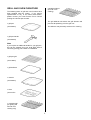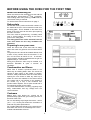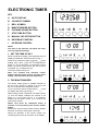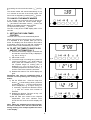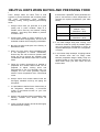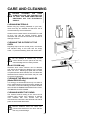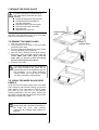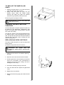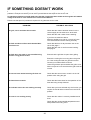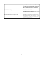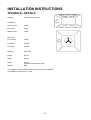
1
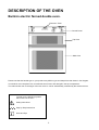
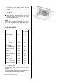
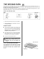
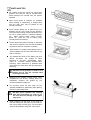
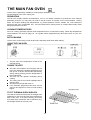
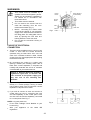
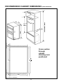
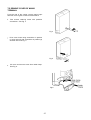
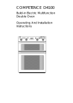
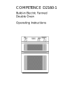
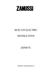
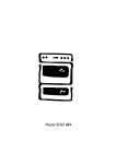
COMPETENCE D2160
Build-in Electric Fanned
Double Oven
Operating And Installation
Instructions
IMPORTANT SAFETY INFORMATION
These warnings are provided in the interests of your safety. Ensure that you understand them all before installing
or using the cooker. Your safety is of paramount importance. If you are unsure about any of the information in
this book contact the Customer Care Department. Telephone 0870 5 350350
Stand clear when opening the drop down oven
doors. Support the doors using the handles
until fully open.
Never leave the cooker unattended when
the oven door is open.
Do not place sealed cans or aerosols inside the
oven. They may explode if they are heated.
Ensure that all control knobs are in the OFF
position when not in use.
Do not stand on the cooker or on the open
oven doors.
Do not hang towels, dishcloths or clothes from
the cooker or its handles. They are a safety
hazard.
INSTALLATION
The cooker must be installed according to the
instructions supplied.
The cooker must be installed in an adequately
ventilated room.
NOTE: It is imperative that the appliance is left
in the base to protect both the appliance and
the floor.
This cooker is heavy and care must be taken
when moving it. Do not try to move the cooker
by pulling the door handles.
Warning: Do Not attempt to lift this appliance
by the handles.
All packaging, both inside and outside the
cooker must be removed before the cooker is
used.
It is dangerous to alter the specifications or
modify the cooker in any way.
After installation please dispose of the
packaging with due regard for safety and the
environment. Your local authority can arrange
this.
CLEANING AND MAINTENANCE
The cooker is heavy and care must be taken
when moving it.
For Hygiene and safety reasons this cooker
should be kept clean at all times.
A
build-up of fats or other
foodstuffs could result in a fire especially
in the grill pan.
This cooker should be kept clean at all times. A
build-up of fats or other foodstuffs could result
in a fire, especially in the grill pan.
Do not leave cookware containing foodstuffs,
e.g. fat or oil in the cooker in case it is
inadvertently switched on.
Always allow the cooling fan to cool the cooker
down before switching off at the wall prior to
carrying out any cleaning / maintenance work.
Only clean this cooker in accordance with the
instructions given in this book.
CHILD SAFETY
Do not allow young children to play with any
part of the packaging.
This cooker is designed to be operated by
adults. Young children must not be allowed to
tamper with the controls or play near or with
the cooker.
The cooker and accessible parts especially
around the grill area become hot when the
cooker is in use. Keep children away until it has
cooled.
DURING USE
SERVICE
This cooker has been designed for domestic
use to cook edible foodstuffs only, and must
not be used for any other purpose.
Take great care when heating fats and oils as
they will ignite if they become too hot.
Never place plastic or any other material which
may melt in or on the oven.
Do not stand too close to the oven or grill while
in use as warm air will exhaust from the grill
cavity and the vents on the front frame of the
cooker.
Always use oven gloves to remove and place
food in the oven.
Ensure that all vents are left unobstructed to
ensure ventilation of the oven cavity.
Never line any part of the cooker with
aluminium foil.
Repairs should not be carried out by
inexperienced persons as this may cause injury
or serious malfunction. This cooker should be
serviced by an authorised Service Engineer
and only genuine approved spare parts should
be used. Details of servicing and repair
arrangements are supplied on page 35 of this
book.
AT THE END OF THE COOKERS LIFE
When the time comes to dispose of your
cooker please contact your local Council
Authority. They can arrange to dispose of the
cooker in a safe and controlled manner. The
number will be in the telephone book.
Please read this
instruction book carefully
before use and retain
for future reference.
1
CONTENTS
FOR THE USER
FOR THE INSTALLER
Important Safety Information . . . . . . . . . . . . . . . . 1
Description Of The Oven . . . . . . . . . . . . . . . . . . . .
Getting To Know Your Oven . . . . . . . . . . . . . . . . . . .
The Cooling Fan For The Controls . . . . . . . . . . . . .
Control Panel Indicator Neons . . . . . . . . . . . . . . . . .
Grill And Oven Furniture . . . . . . . . . . . . . . . . . . . . . . .
Before Using For The First Time . . . . . . . . . . . . . . .
When First Switching On . . . . . . . . . . . . . . . . . . . . . .
Rating Plate . . . . . . . . . . . . . . . . . . . . . . . . . . . . . . . . . . .
Condensation And Steam . . . . . . . . . . . . . . . . . . . . .
Cookware . . . . . . . . . . . . . . . . . . . . . . . . . . . . . . . . . . . .
Technical Details . . . . . . . . . . . . . . . . . . . . . . . . . . . 32
Warnings . . . . . . . . . . . . . . . . . . . . . . . . . . . . . . . . . . . . . 33
3
4
4
4
5
6
6
6
6
6
The Electronic Timer . . . . . . . . . . . . . . . . . . . . . . . . . 7
The Dual Grill . . . . . . . . . . . . . . . . . . . . . . . . . . . . . . .
Using The Grill . . . . . . . . . . . . . . . . . . . . . . . . . . . . . . .
Things To Note . . . . . . . . . . . . . . . . . . . . . . . . . . . . . .
The Grill Pan And Handle . . . . . . . . . . . . . . . . . . . . .
Hints And Tips . . . . . . . . . . . . . . . . . . . . . . . . . . . . . . .
Grilling Chart . . . . . . . . . . . . . . . . . . . . . . . . . . . . . . . . .
11
11
11
12
12
13
The Second Oven . . . . . . . . . . . . . . . . . . . . . . . . . . .
Using The Second Oven . . . . . . . . . . . . . . . . . . . . .
Things To Note . . . . . . . . . . . . . . . . . . . . . . . . . . . . . .
To Fit The Second Oven Shelf . . . . . . . . . . . . . . . .
Hints And Tips . . . . . . . . . . . . . . . . . . . . . . . . . . . . . . .
14
14
14
14
15
The Main Fan Oven . . . . . . . . . . . . . . . . . . . . . . . . .
Using The Fan Oven . . . . . . . . . . . . . . . . . . . . . . . . .
Things To Note . . . . . . . . . . . . . . . . . . . . . . . . . . . . . .
To Fit The Main Oven Shelves . . . . . . . . . . . . . . . .
Hints And Tips . . . . . . . . . . . . . . . . . . . . . . . . . . . . . . .
16
16
16
16
17
20
20
20
20
Care And Cleaning . . . . . . . . . . . . . . . . . . . . . . . . . .
Cleaning Materials . . . . . . . . . . . . . . . . . . . . . . . . . . .
Cleaning The Outside Of The Oven . . . . . . . . . . .
Cleaning Inside The Ovens . . . . . . . . . . . . . . . . . . .
Cleaning The Door Glass . . . . . . . . . . . . . . . . . . . . .
Cleaning The Grill And Oven Furniture . . . . . . . .
Replacing An Oven Light Bulb . . . . . . . . . . . . . . . .
23
23
23
23
24
25
25
If Something Doesn't Work . . . . . . . . . . . . . . . . .
Guarantee Conditions . . . . . . . . . . . . . . . . . . . . . .
Service and Spare Parts . . . . . . . . . . . . . . . . . . . .
Service Force Centres . . . . . . . . . . . . . . . . . . . . . .
26
28
29
30
33
34
34
35
36
36
Making The Electrical Connections . . . . . . . . .
Preparing Cable . . . . . . . . . . . . . . . . . . . . . . . . . . . . . .
To Remove Cover Of Mains Terminal . . . . . . . . .
Connecting To The Mains Terminal . . . . . . . . . . .
Connecting To A Hob Or Cooker Point . . . . . . . .
Checking Electrical Connections . . . . . . . . . . . . . .
36
36
37
38
38
38
Fitting Into The Cabinet . . . . . . . . . . . . . . . . . . . . . 39
Oven Cooking Chart . . . . . . . . . . . . . . . . . . . . . . . . 18
Roasting Chart . . . . . . . . . . . . . . . . . . . . . . . . . . . . . . 19
Defrosting . . . . . . . . . . . . . . . . . . . . . . . . . . . . . . . . . .
Using Defrost Feature . . . . . . . . . . . . . . . . . . . . . . . .
Things To Note . . . . . . . . . . . . . . . . . . . . . . . . . . . . . .
Hints And Tips . . . . . . . . . . . . . . . . . . . . . . . . . . . . . . .
Helpful Hints When Buying And Preparing
Food
.....................................
Choice Of Electrical Connection . . . . . . . . . . . .
Things To Note . . . . . . . . . . . . . . . . . . . . . . . . . . . . . .
Preparing Cabinet For Fitting Oven . . . . . . . . . . .
Recommended Cabinet Dimensions . . . . . . . . . .
How To Finish Unpacking . . . . . . . . . . . . . . . . . . . .
Tools Required . . . . . . . . . . . . . . . . . . . . . . . . . . . . . . .
22
2
DESCRIPTION OF THE OVEN
Build-in electric fanned double oven.
Electronic Timer
Control Panel
Top Oven
Main Oven
Please note that the handle type on your product may differ in type and shape from that shown in the diagram.
Your build-in oven comprises of a conventional second oven and dual grill in the top compartment.
The main fanned oven is the larger of the two ovens. It can be automatically controlled by the electronic timer.
To help you the following symbols
will be found in the text.
Safety Instructions
1, 2, 3,
Step by Step Instructions
Hints and Tips
3
GETTING TO KNOW YOUR OVEN
The Control Panel
A - Main Oven Temperature Control
B - Main Oven Indicator Neon
C - Electronic Timer
D - Dual Grill Control
E - Grill Indicator Neon
F - Second Oven Indicator Neon
G - Second Oven Temperature Control
The Cooling Fan for the Controls
The cooling fan comes on immediately when the grill is switched on and after a short time when either of the
ovens are in use. It may run on after the controls are switched off until the appliance has cooled. During the
initial period the cooling fan may turn ON and OFF, this is quite normal.
Control Panel Indicator Neons
These lights indicate whether the grill or ovens are switched ON. In the case of the ovens, the neons also
indicate when the set temperature has been reached. The indicator neon will go out when the oven has
reached the set temperature. It will turn on and off during cooking to show that the oven temperature is being
maintained.
If the neons do not operate as the instructions indicate the controls have been incorrectly set. Return all
controls to zero and reset following the instructions for the required setting.
4
2 straight shelves
(for main oven
cooking)
GRILL AND OVEN FURNITURE
The following items of grill and oven furniture have
been supplied with the cooker. If you require
replacements of any of the items listed below,
please contact your local Service Force Centre
quoting the relevant part number.
The grill deflector sits above the grill element and
prevents fat splashing onto the grill roof.
1 grill pan
The deflector may be easily removed for cleaning.
(311409401)
1 grill pan handle
(311468100)
Note
If you require an additional handle for your grill pan,
this can be ordered from your local AEG Service
Centre by quoting part number 311479800\6
1 grill pan grid
(311419801)
1 grill deflector
1 meat tin
(311409401)
1 trivet
(311419701
1 cranked shelf
(for grilling and
second oven
cooking only)
5
BEFORE USING THE OVEN FOR THE FIRST TIME
When first switching on
When the cooker is first switched on at the wall the
timer will flash. Press buttons ( and ) together,
while holding them down press (+) button until the
correct time of day is reached.
To use the timer refer to instructions on page 7.
Rating plate
Record the model, product and serial numbers on
the inside back cover of this instruction book from
the rating plate. This is situated on the lower front
frame of the oven and can be seen upon opening
the main oven door.
The oven must be protected by a suitably rated
fuse or circuit breaker. The rating of the oven is
given on the rating plate.
The rating plate must not be removed from the
oven front frame as this may invalidate the
guarantee.
Preparing to use your oven
Clean the ovens with a soft cloth and hot soapy
water and wash the grill and oven furniture before
use.
The grill and ovens should be heated without food
to burn off any residue from the elements. To do
this, run the ovens at 220°C for 10 - 15 minutes.
The procedure should be repeated with the grill for
approximately 5 - 10 minutes.
During this period an odour may be emitted, it is
therefore advisable to open a window for
ventilation.
Condensation and Steam
When food is heated it produces steam in the
same way as a boiling kettle does. The ovens are
vented to allow some of this steam to escape.
However, always stand back from the cooker when
opening the oven doors to allow any build up of
steam or heat to be released. If the steam comes
into contact with a cool surface on the outside of
the cooker, e.g. a trim, it will condense and
produce water droplets. This is quite normal and is
not caused by a fault on the cooker.
To prevent discolouration occurring, regularly wipe
away condensation and any soilage from the
cooker surfaces.
Cookware
Baking trays, oven dishes etc., should not be
placed directly against the grid covering the fan at
the back of the oven.
Do not use baking trays larger than 30cm x 35cm
(12" x 14") as they will restrict the circulation of
heat and may affect performance.
Do not place bakeware directly on the second oven
base when the oven is on as damage to the oven
enamel and bakeware will occur.
6
A
ELECTRONIC TIMER
B C
KEY
A AUTO DISPLAY
B
COOKPOT SYMBOL
C
BELL SYMBOL
D
MINUTE MINDER BUTTON
E
COOKING HOURS BUTTON
F
STOP TIME BUTTON
G
MANUAL SELECTOR BUTTON
H
DECREASE CONTROL
I
INCREASE CONTROL
D
NOTE:
The time of day must be set before the main
oven will operate manually.
1. SET THE TIME OF DAY
When the electricity supply is first switched ON, the
display will flash both 0.00 and AUTO as Fig. 1.
Press the two buttons marked ( ) and ( ) while
holding them down, press the increase control
button (+) and if necessary, the decrease control
button (-) until the correct time on the 24 hour clock
is reached, e.g. 10.00am as Fig. 2.
The AUTO symbol will go out.
Note: The increase and decrease control
buttons operate slowly at first, and then more
rapidly. They should be pressed separately.
Fig. 1
Fig. 2
2. THE MINUTE MINDER
The minute minder gives an audible reminder at
the end of any period of cooking up to 23 hrs 59
mins. It is not part of the automatic control.
To set, press the minute minder button (
) and
the display will read 0 . 00 as Fig.3.
While holding it down, depress the increase control
(+) until the display indicates the interval to be
timed, e.g. 1hr 45 mins as Fig. 4. If necessary
depress the decrease control (-) to achieve the
correct time interval.
NOTE: This must be completed within 5
seconds of first pressing the minute minder
button.
Release the minute minder button and the display
will return to the time of day after 5 seconds.
During the operation of the minute minder, the
remaining time period can be shown in the display
Fig. 3
Fig. 4
7
E
F
G
H
I
by pressing the minute minder button (
) as Fig.
5.
The minute minder will sound intermittently for up
to 7 minutes at the end of the timed period. The
sound can be stopped by pressing the ( ) button.
TO CANCEL THE MINUTE MINDER
If you change your mind and want to cancel the
minute minder, press the minute minder button
( ) and then the decrease control ( - ) until 0 . 00
shows in the display and the alarm sounds.
To stop the sound, press (
) button.
The time of day shows in the display after a few
seconds.
Fig. 5
3. SETTING THE OVEN TIMER
CONTROL
The main oven only can be automatically timed.
When using the timer control for the very first time,
it is advisable to let it operate while you are at
home. The displays can be checked to show that it
is operating correctly and you will feel confident to
leave a meal to cook automatically in the future.
A) TO SET THE TIMER TO SWITCH ON
AND OFF AUTOMATICALLY
i)
Ensure the electricity supply is switched ON
and that the correct time of day is displayed,
e.g. 9.a.m. as Fig. 6.
ii) Place food in oven.
iii) To set the length of cooking time, press the
cooking hours button (
) while holding it
down, press the increase control ( + ) until
the required length of cooking time is
displayed, e.g. 2 hrs 15 mins as Fig. 7. If
necessary depress the decrease control ( - )
until the correct time interval is achieved.
iv) Release the buttons. The AUTO display will
glow.
Remember, this must be completed within 5
seconds of first pressing the cooking hours
button.
v) Set the STOP time. Press the stop time
button ( ), while holding it down, press the
increase control ( + ) until the required stop
time is displayed, e.g. 12.15p.m. as Fig. 8.
If necessary depress the decrease control
( - ) until the correct time interval is
achieved.
vi) Release the buttons. The time of day will
be displayed after 5 seconds.
vii) Set the main oven control to the required
temperature. The oven indicator neon
should be OFF and the AUTO display will
glow.
Note: When the automatic timed period starts,
the oven indicator neon will turn ON and OFF
during cooking. The cookpot symbol will show
in the display.
Fig. 6
Fig. 7
Fig. 8
8
B) TO SET THE TIMER TO SWITCH OFF
ONLY
i)
Ensure the electricity supply is switched ON
and that the correct time of day is displayed,
e.g. 10.00am as Fig. 9.
ii) Place food in oven.
iii) To set the length of cooking time, press the
cooking hours button (
), while holding it
down, depress the increase control ( + )
until the required length of cooking time is
displayed, e.g. 2 hrs 15 mins as Fig. 10.
Depress the decrease control (-) if
necessary.
Fig. 9
iv) Release the buttons. The AUTO display will
glow and the time of day will be displayed
after 5 seconds.
v) Set the oven temperature. The oven
indicator neon should be ON.
Fig. 10
vi) To check the stop time during the cooking
period, simply press the stop time button
(
) and the stop time will be displayed, as
Fig. 11.
Fig. 11
4. TO
CANCEL
PROGRAMME
i)
AN
AUTOMATIC
To cancel an automatic programme, press
(
) button. The AUTO display will go out
and the cookpot symbol will light, as Fig.12.
ii) Turn off oven control.
5. TO RETURN
MANUAL
THE
Fig. 12
COOKER
TO
At the end of a timed cooking period, the AUTO
display will flash and an alarm will sound for up
to 7 minutes.
i) To stop the sound press any of the first
three buttons, as Fig. 13.
ii) Turn off oven control. AUTO display will
continue to flash.
iii) Press (
) button. See Fig. 14.
The AUTO display goes out and the
cookpot symbol will show.
iv) Turn the oven control on to check the oven
operates normally. The oven indicator neon
will glow.
v) Turn off the oven control.
Fig. 13
Fig. 14
9
6. THINGS TO NOTE
l A programme may be cancelled by returning
the cooking time to zero. Press the cooking
hours button (
) while holding it down press
( - ) button until 0.00 is displayed as Fig. 15.
Release all buttons. The AUTO display will
flash. Reset the cooker to manual by pressing
the (
) button.
In the event of an interruption of the electricity
supply, the timer will reset itself to zero, and all
programming will be cancelled.
Fig.15
7. AUTOMATIC COOKING
It is advisable to leave food in the oven for as
short a time as possible before automatic
cooking. Always ensure commercially prepared
food is well within its use by date and that
home prepared food is fresh and of good
quality.
When cooking is complete, do not leave food to
stand in the oven, but remove and cool it
quickly if the food is not to be consumed
immediately.
Always ensure food in the oven has been
covered before cooking if it is not possible to
remove food immediately after cooking.
10
THE DUAL GRILL
CAUTION - ACCESSIBLE PARTS MAY BECOME HOT WHEN THE GRILL IS
IN USE. CHILDREN SHOULD BE KEPT AWAY.
The grill is a dual circuit grill which means that the full area of the grill can be used or for economy purposes,
the centre section only can be used when cooking smaller quantities of food.
USING THE GRILL
1.
To operate the grill turn the grill control
clockwise for full grill or anticlockwise for centre
section only.
2.
The highest number represents the hottest
setting and the lowest the coolest setting.
3.
Ensure the second oven control is in the OFF
position '0'.
THE GRILL DOOR MUST BE LEFT
OPEN DURING GRILLING.
IF
CLOSED THE ELEMENTS WILL
SWITCH OFF AND THE OVEN
LIGHT WILL TURN ON AND OFF
AS A WARNING
THINGS TO NOTE
l The cooling fan for the controls will operate in
conjunction with the grill. For more information
on the operation of the cooling fan see page 4.
l The grill indicator neon will glow until the
desired power level has been reached. It will
turn ON and OFF periodically during cooking
showing that the temperature is being
maintained.
l The outer grill element may appear to glow
slightly brighter than the inner element. This is
quite normal.
l The cranked shelf MUST only be used in the
grill compartment.
l Some smoke from fat splashes may be evident
as the grill cleans itself.
11
THE GRILL PAN AND HANDLE
The grill pan is supplied with a removable handle.
1. To attach the handle, place the wirework under
the cut out in the pan so that the metal plate
hooks over the top of the grill pan.
1.
2. Slide the handle to the left and over the central
bump on the grill pan.
Ensure the handle is correctly located.
The grill pan handle should be in place
when grilling.
2.
Place the grill pan on the shelf so that the pan is
positioned centrally beneath the grill.
3. To remove the handle, slide the handle to the
right and lift the handle away from the cut out
on the grill pan.
3.
HINTS AND TIPS
l Most foods should be placed on the grid in the
grill pan to allow maximum circulation of air to
lift the food out of the fats and juices. Food
such as fish, liver and kidneys may be placed
directly on the trivet or grill pan base if
preferred.
l Use the trivet to keep fat splashing to a
minimum when grilling meat items.
l Adjust the grid and grill pan runner position to
allow for different thicknesses of food. Position
the food close to the element for faster cooking
and further away for more gentle cooking.
l Food should be thoroughly dried before grilling
to minimise splashing. Brush lean meats and
fish lightly with a little oil or melted butter to
keep them moist during cooking.
l Accompaniments such as tomatoes and
mushrooms may be placed around the outer
edges or underneath the grid when grilling
meats.
l When toasting bread, we suggest that the top
runner position is used with the grid in its 'high'
position.
12
l Preheat the grill on full setting for a few minutes
to seal meat or for toasting. Adjust the heat
setting and the shelf as necessary during
cooking.
l The food should be turned over during cooking
as required.
l When using the centre section grill, ensure food
is placed centrally on the grilling grid directly
beneath the grill element.
Note
If you require an additional handle for your grill pan,
this can be ordered from your local AEG Service
Centre by quoting part number 311479800\6.
GRILLING CHART
FOOD
SHELF
GRILL TIME
(mins in total)
Toast
2crk.
4-6
Bacon Rashers
2crk.
10
Beefburgers
2crk.
10-15
Chicken Joints
2crk.
30-40
Chops - Lamb
Pork
2crk.
2crk.
15-20
20-30
Fish - Whole
Trout/Mackerel
2crk.
2crk.
15-25
Fillets - Plaice/Cod
2crk.
15
Kebabs
2crk.
20-30
Kidneys - Lamb/Pig
2crk.
8-12
Sausages
2crk.
20-30
Steaks - Rare
Medium
Well Done
2crk.
2crk.
2crk.
6-12
12-16
14-20
Toasted Sandwiches
2crk.
3-4
crk. = Cranked Shelf
Shelf positions are counted from the bottom
upwards.
The times quoted above are given as a guide and
should be adjusted to suit personal taste.
The cranked shelf should be used for grilling and
second oven cooking only.
13
THE SECOND OVEN
The second oven is the smaller of the two ovens. It is heated by elements in the top and bottom of the oven. It
is designed for cooking smaller quantities of food on one shelf. It gives especially good results if used to cook
fruit cakes, sweet and savoury flans or quiche.
The second oven is also ideal for use as a warming compartment to warm dishes and keep food hot. Use a
temperature setting of 80° - 100°C on the second oven temperature control.
USING THE SECOND OVEN
1. Ensure the grill control is in the off, 'O' position.
2. Turn the second oven temperature control to
the required setting.
THINGS TO NOTE
l The second oven indicator neon will glow until
the oven has reached the desired temperature
and then go out. It will turn ON and OFF
periodically during cooking showing that the
temperature is being maintained.
l The cooling fan for the controls will operate,
after a period of time. For more information on
the operation of the cooling fan, see page 4.
l The internal oven light will come on.
Dishes, tins or trays should not be
placed directly on the oven floor as it
becomes very hot and damage will
occur.
TO FIT THE SECOND OVEN SHELF
The cranked shelf should be fitted with the straight
rods uppermost on the frame and the forms
towards the back of the oven. If not fitted correctly
the anti-tilt and safety stop mechanism will be
affected.
14
HINTS AND TIPS
l All cooking should be carried out using shelf
positions one and two using a cranked shelf.
Shelf positions are counted from the bottom
upwards.
l When more space is required, for example
when roasting or casseroling, a straight shelf
from the main oven may be placed on the
second oven base.
l There should always be at least 2.5cm (1")
between the top of the food and the element.
This gives best cooking results and allows room
for rise in yeast mixtures, Yorkshire puddings
etc. When cooking cakes, pastry, scones,
bread etc., place the tins or baking trays
centrally below the element.
l Ensure that food is placed centrally on the shelf
and there is sufficient room around the baking
tray/dish to allow for maximum circulation.
l Stand dishes on suitably sized baking trays to
prevent spillage onto the oven base and to help
reduce cleaning.
l The material and finish of the baking tray and
dishes will affect the degree of
browning of the food. Enamelware,
heavy or non-stick utensils increase
browning. Shiny aluminium or polished
trays reflect the heat away and give less
browning.
base
dark,
base
steel
base
DO NOT use the grill pan or meat tin as a
baking tray as this will increase base
browning of the food.
l Because of the smaller cooking space, lower
temperatures and shorter cooking times are
sometimes required. Be guided by the
recommendations on page 18.
l For economy leave the door open for the
shortest possible time, particularly when placing
food into a pre-heated oven.
DO NOT place cookware and cooking
pots with rough bases e.g. cast iron on
the oven door as damage to the glass
may occur.
l When roasting, use the trivet in the meat tin.
Fat and meat juices will drain into the meat tin
and can be used to make gravy. The trivet also
prevents fat splashes soiling the oven interior.
15
THE MAIN FAN OVEN
The fan oven is particularly suitable for cooking larger quantities of food.
The advantages of fan oven cooking are:
PREHEATING
The fan oven quickly reaches its temperature, so it is not usually necessary to preheat the oven. Without
preheating however, you may find you need to add an extra 5-10 minutes on the recommended cooking
times. For recipes needing high temperatures, e.g. bread, pastries, scones, soufflés, etc., best results are
achieved if the oven is preheated first. For best results when cooking frozen or cooked chilled ready meals
always preheat the oven first.
COOKING TEMPERATURES
Fan oven cooking generally requires lower temperatures than conventional cooking. Follow the temperatures
recommended in the chart on page 18. As a guide reduce temperatures by about 20°C-25°C for your own
recipes.
BATCH BAKING
The fan oven cooks evenly on both shelf levels, especially useful when batch baking.
USING THE FAN OVEN
1. Turn the main oven temperature control to the
required setting.
THINGS TO NOTE
l The main oven indicator neon will glow until the
l
l
l
l
oven has reached the desired temperature and
then go out. It will turn ON and OFF periodically
during cooking showing that the temperature is
being maintained.
The oven fan will operate continually during
cooking.
The cooling fan for the controls operates after a
period of time.
The internal oven light will come on.
If an automatic programme has been set the
oven fan and light do not come on until cooking
begins.
TO FIT THE MAIN OVEN SHELVES
The shelves should be fitted with the straight rods
uppermost on the frame and the forms towards the
back of the oven. If not fitted correctly the anti-tilt
and safety stop mechanism will be affected. Only
use straight shelves in the main oven.
16
HINTS AND TIPS
l Arrange the shelves in the required positions
before switching the oven ON. Shelves are
numbered from the bottom upwards.
l When cooking more than one dish in the fan
oven, place dishes centrally on different
shelves rather than cluster several dishes on
one shelf, this will allow the heat to circulate
freely for the best cooking results.
l When batch baking one type of food, e.g.
Victoria sandwich cakes, those of similar size
will be cooked in the same time.
Do not use the cranked shelf from the
grill in the main oven.
l It is recommended that when baking larger
quantities the shelf positions should be evenly
spaced to suit the load being cooked. A slight
increase in cooking time may be necessary.
DO NOT place cookware and cooking
pots with rough bases e.g. cast iron on
the oven door as damage to the glass
may occur.
l DO NOT place baking trays directly on the
oven floor as it interferes with the oven air
circulation and can lead to base burning; use
the lower shelf position. However, non-critical
dishes may be placed on the oven base when
more space is required.
l The use of excessively high temperatures can
cause uneven browning. It may be necessary
to reduce temperatures slightly. Refer to the
recommendations given in the oven cooking
chart see page 18.
l Do use the trivet in the meat tin to prevent fat
splashing and keep oven soilage to a minimum.
17
OVEN COOKING CHART
The oven temperatures are intended as a guide only. It may be necessary to increase or decrease the
temperatures by 10°C to suit individual preferences and requirements.
FAN OVEN
FOOD
Biscuits
Bread
Bread rolls/buns
Cakes:
Small & Queen
Sponges
Victoria Sandwich
Madeira
Rich Fruit
Christmas
Gingerbread
Meringues
Flapjack
Shortbread
Casseroles: Beef/lamb
Chicken
Convenience Foods
Fish
Fish Pie (Potato Topped)
Fruit Pies, Crumbles
Milk Puddings
Pasta, Lasagne etc.
Pastry:
Choux
Eclairs,Profiteroles
Flaky/Puff Pies
Shortcrust
Mince Pies
Meat Pies
Quiche,Tarts,Flans
Patés and Terrines
Roasting Meat, Poultry
Scones
Shepherd's Pie
Soufflés
Vegetables: Baked Jacket Potatoes
Roast Potatoes
Stuffed Marrow
Stuffed Tomatoes
Yorkshire Puddings: Large
Individual
SHELF
POSITION
Shelf
positions
are not
critical
but
ensure
that oven
shelves
are
evenly
spaced
when
more
than one
is
used
SECOND OVEN
TEMP
SHELF
POSITION
COOKING
TEMP °C
180-190
200-220
200-220
160-170
160-170
160-170
140-150
130-140
130-140
1 crk.
1 crk.*
1 crk.
1 crk.
1 crk.
1 crk.
1 crk.
1 crk.
1 crk.
170-190
200-220
200-220
180-190
160-170
160-170
140-150
130-140
130-140
COOKING
140-150
1 crk.
140-150
80-100
1 crk.
90-100
170-180
1 crk.
170-180
130-140
1 crk.
140-150
140-160
1 crk.*
140-160
180-190
1 crk.*
180-190
Follow manufacturer's instructions
170-190
1 crk.
170-190
190-200
1crk.*
190-200
190-200
1 crk.
190-200
130-140
1 crk.
140-150
190-200
1 crk.
170-180
190-200
1 crk.
180-190
170-180
1 crk.
170-180
210-220
1crk.*
210-220
190-200
1 crk.
190-200
190-210
1crk.*
190-210
180-210
1 crk.
180-200
150-160
1 crk.
150-160
160-180
1crk.*
160-180
210-220
1 crk.
220-230
190-200
1crk.*
190-200
170-180
1 crk.
170-180
180-190
1 crk.
180-190
180-190
1 crk.
180-190
180-190
1 crk.
180-190
180-190
1 crk.
180-190
210-220
1 crk.
200-210
200-210
1 crk.
200-210
crk. = cranked shelf
* or on a straight shelf on the oven base.
Note: Shelf positions are counted from the bottom of the oven.
Do not use the cranked shelf from the grill in the main oven.
18
APPROX.
COOK TIME (m)
10 - 20
25 - 30
15 - 20
18 - 25
18 -20
18 -25
1¼ - 1½h
2¼ - 2½h
3 - 4½h
depends on size
1¼ - 1½h
2½ - 3h
25 - 30
45 - 65
2½ - 3h
1¼ - 1½h
20 -30
20 - 25
40 - 50
1½ - 2h
40 - 45
30 - 35
20 - 30
25 - 40
15 - 20
25 - 35
25 -45
1-1½h
see roasting chart
8 - 10
30 - 40
20 - 30
1-1½h
1-1½h
30 - 35
15 - 20
25 - 40
15 - 25
ROASTING CHART
ROASTING CHART
INTERNAL TEMPERATURES Rare : 50-60°C; Medium : 60-70°C; Well done :70-80°C
MEAT
SECOND/FAN
OVEN
COOKING TIME
Beef
160-180°C
20-35 min per ½kg/1lb
and 20-35 min over
Beef,
boned
160-180°C
20-35 min per ½kg/1lb
and 25-35 min over
Mutton
and Lamb
160-180°C
25-35 min per ½kg/1lb
and 25-35 min over
Pork
and Veal
160-180°C
30-40 min per ½kg/1lb
and 30-40 min over
Ham
160-180°C
30-40 min per ½kg/1lb
and 30-40 min over
Chicken
160-180°C
15-20 min per ½kg/1lb
and 20 min over
Turkey
and Goose
160-180°C
15-20 min per ½kg/1lb up to
3½kg/7lb then 10 min per ½kg/1lb
over 3½kg/7lb
Duck
160-180°C
25-35 min per ½kg/1lb and 25-30
min over
Pheasant
160-180°C
35-40 min per ½kg/1lb and 35-40
min over
Rabbit
160-180°C
20 min per ½kg/1lb
and 20 min over
Potatoes
with meat
160-180°C
according to size
Potatoes
without meat
180-190°C
according to size
The roasting temperatures and times given in the chart should be adequate for most joints, but slight
adjustments may be required to allow for personal requirements and the shape and texture of the meat.
However, lower temperatures and longer cooking times are recommended for less tender cuts or larger joints.
Wrap joints in foil if preferred, for extra browning uncover for the last 30 - 60 min. cooking time.
19
DEFROSTING
This main oven function enables you to defrost most foods without heat faster than some conventional
methods as the oven fan circulates air around the food. It is particularly suitable for delicate frozen foods which
are to be served cold e.g. cream filled gateaux, cakes covered with icings or frostings, cheesecakes, biscuits,
scones etc.
USING DEFROST FEATURE
1. Turn the main oven temperature control to the
defrost setting.
THINGS TO NOTE
l The oven indicator neon may glow and turn on
and off when defrosting.
l The oven fan and oven light will come on.
l The cooling fan does not operate.
HINTS AND TIPS
l Place the frozen food in a single layer where
possible and turn it over half way through the
defrosting process.
l The actual speed of defrosting is influenced by
room temperature. On warm days defrosting
will be faster than on cooler days.
l It is preferable to thaw fish, meat and poultry
slowly in the fridge. However, this process can
be accelerated by using the defrost function.
Small or thin fish fillets, frozen peeled prawns,
cubed or minced meat, liver, thin chops, steaks
etc., can be thawed in 1 - 2 hours.
l A 1kg/2¼lb oven ready chicken will be thawed
in approximately 5 hours. Remove the giblets
as soon as possible during the thawing
process.
20
l Joints of meat up to 2kg/4½lb in weight can be
thawed using the defrost function.
l All joints of meat and poultry must be thawed
thoroughly before cooking.
l Always cook thoroughly immediately after
thawing.
l DO NOT leave food at room temperature once
it is defrosted. Cook raw food immediately or
store cooked food in the fridge.
l Care must always be taken when handling
foods in the home. Always follow the basic
rules of food hygiene to prevent bacterial
growth and cross contamination when
defrosting, preparing, cooking cooling and
freezing foods.
21
HELPFUL HINTS WHEN BUYING AND PREPARING FOOD
Care must be taken when handling foods in the
home. Always follow the basic rules of food
hygiene to prevent bacterial and microbial growth
and cross contamination when preparing,
reheating, cooking, cooling, defrosting and freezing
foods.
10. Cook meat thoroughly - use a meat
thermometer if preferred, which penetrates the
joint to check that the centre temperature has
reached the required temperature (see table
below).
1. Always ensure food you purchase is of good
quality and in prime condition. Shop at a
reliable source and buy the 'freshest' looking
package - avoid shop worn labels or produce
covered in dust.
2. Avoid buying chilled or frozen products if you
cannot store them straight away. The use of an
insulated container when shopping is advisable.
MEAT
TEMPERATURES
Beef
Rare - 60°C
Medium - 70°C
Well Done - 80°C
Pork
Well Done - 80°C
Lamb
Medium - 70°C
Well Done - 80°C
11. If not eaten straight away after cooking, food
should be cooled as quickly as possible (within
one hour) and then refrigerated or frozen as
required. Do not put hot food into a refrigerator
or freezer.
3. Buy and consume foods prior to the 'Sell by' or
'Best Before' date.
4. When you arrive home, place perishable foods
in the refrigerator or freezer immediately.
Ensure they are well covered to prevent them
drying out and to prevent any possible cross
contamination with bacteria from raw to cooked
foods.
12. In the kitchen keep worktops, chopping boards
and utensils clean with hot soapy water
between preparation stages. Ideally, keep one
chopping board for raw meat and another for
other foods. Keep your dish cloths and tea
towels clean.
5. Follow the cooking instructions on packets of
prepacked and cooked chilled foods, but be
prepared to adjust cooking times and
temperatures to suit your particular oven. For
example, the Fan Oven generally requires
20-25°C lower temperature than conventional
ovens.
6. Always ensure that cooked chilled foods are
thoroughly reheated until they are piping hot
throughout.
7. It is preferable to defrost frozen foods slowly in
the refrigerator. Alternatively, a microwave
cooker or the Defrost function on your oven
may be used.
8. Always cook defrosted foods immediately after
thawing. Thawed food should never be
refrozen.
9. Joints of meat and poultry should be thoroughly
defrosted before cooking.
22
CARE AND CLEANING
BEFORE
CLEANING
THE
OVEN
ALWAYS ALLOW THE COOLING FAN
TO COOL THE OVEN DOWN BEFORE
SWITCHING OFF THE ELECTRICITY
SUPPLY.
CLEANING MATERIALS
Before using any cleaning materials on your oven,
check that they are suitable and that their use is
recommended by the manufacturer.
Cleaners that contain bleach should NOT be used
as they may dull the surface finishes. Harsh
abrasives and scourers should also be avoided as
damage will occur.
CLEANING THE OUTSIDE OF THE
OVEN
Regularly wipe over the control panel, oven doors
and handles using a soft cloth and hot soapy
water. To prevent streaking finish with a soft cloth.
Do not attempt to remove any of the
control knobs from the panel as this may
cause damage and is a safety hazard.
Model D2160M only
Stainless steel cream cleaners can be abrasive
and should be avoided as damage to the surface
finish can occur. Washing up liquid and hot water
or liquid stainless steel cleaners such as Homecare
Stainless Steel Cleanser and Polish may be used
to remove fingermarks.
CLEANING THE BRASS HANDLES
(Model D2160G only)
It is strongly recommended that only hot water to
which a little washing up liquid has been added and
a soft cloth is used for cleaning the brass handles.
ANY OTHER CLEANING MATERIALS WILL DULL
THE BRASS PLATED FINISH.
CLEANING INSIDE THE OVENS
The vitreous enamel coating in the ovens can be
cleaned using normal oven cleaners or aerosol
oven cleaners with care. Ensure that the
manufacturers instructions are followed and that all
parts are well rinsed afterwards.
Aerosol cleaners must not come into
contact with elements or the door seal as
this may cause damage.
23
CLEANING THE DOOR GLASS
To prevent damaging or weakening the
door glass panels avoid the use of the
following:
l Household detergents and bleaches
l Impregnated pads unsuitable for
non-stick saucepans
l Brillo/Ajax pads or steel wool pads
l Chemical oven pads or aerosols
l Rust removers
l Bath/Sink stain removers
Hinge location
point
The main oven and second oven inner door glass
panels are removable for cleaning.
TO REMOVE THE INNER GLASS
Hinge
location point
1. Fully open the oven door.
2. Firmly grasp the rear edge of the inner glass
panel with both hands.
3. Push the glass panel towards you until it clears
the hinge location points at the rear.
4. With one hand, carefully lift the glass panel to
disengage it from the location points under the
handle. (With your other hand, hold the
outer door to ensure it does not spring
shut on removing the inner panel).
5. Close the oven door.
If the door glass panel becomes chipped or
has deep scratches the glass will be
weakened and must be replaced to prevent
the possibility of the panel shattering.
Please contact your local Service Centre
who will be pleased to advise further.
TO CLEAN THE INNER GLASS DOOR
PANELS
Clean the inner door glass panels using a soft cloth
and hot water to which a little washing up liquid has
been added. If the inner panel is heavily soiled,
Hob Brite may be used. Do not use abrasive
cleaning materials on the door glass. Ensure that
all parts are well rinsed and thoroughly dried before
attempting to replace the glass.
Do not clean stainless steel outer panels
(where fitted) with Hob Brite as damage to
the finish will occur. See cleaning
instructions for stainless steel models on
page 23.
24
TO REPLACE THE INNER GLASS
PANEL
1. Holding the glass panel in your right hand fully
open the oven door with your left.
2. Gently ease and push the glass into the
location points under the handle before
lowering and sliding the glass into position
under the hinge location points at the rear.
Ensure the glass is properly located.
Do not attempt to use the oven without the
glass being in place.
CLEANING THE GRILL AND OVEN
FURNITURE
All removable parts, except the grill pan handle can
be washed in the dishwasher. Alternatively soak
them in hot soapy water if heavily soiled. They will
then clean more easily.
The grill pan, meat tin, trivet and grill deflector may
be cleaned using a soap impregnated steel wool
pad. The grill pan grid and oven shelves should be
cleaned using hot soapy water. Soaking first will
make cleaning easier.
REPLACING AN OVEN LIGHT BULB
The type of bulb required is a 300C 25 watt small
Edison Screw.
(Available through AEG Service Centres).
Disconnect the cooker from the
electricity supply before replacing the
bulb.
1. Make sure the cooker is cool before replacing
the bulb.
2. Open the oven door and remove the shelves.
3. Pull the glass bulb cover towards you and then
pull it off. If necessary, use a screwdriver to
carefully lever off the cover, taking care not to
damage the oven cavity.
4. Unscrew the bulb by turning it to the left.
5. Fit a new bulb and then replace the glass bulb
cover.
6. Replace the oven shelves.
7. Restore the electricity supply and reset the time
of day.
25
IF SOMETHING DOESN'T WORK
Please carry out the following checks on your cooker before calling a Service Engineer. It may be that the
problem is a simple one which you can solve yourself without the expense of a service call.
In-guarantee customers should make sure that the checks have been made as the engineer will make a
charge if the fault is not a mechanical or electrical breakdown.
Please note that proof of purchase is required for in-guarantee service calls.
PROBLEM
POSSIBLE SOLUTION
The grill, ovens and timer do not work
Check that the cooker has been wired in to the
cooker supply and is switched on at the wall.
Check that the main cooker fuse is working.
If you have checked the above:
Allow the appliance to cool for a couple of hours.
The cooker should now be working normally.
The Grill and Second Oven work but the Main
Oven does not.
Check that the time of day has been set on the
clock. See page 7.
Check that the oven is set for manual cooking.
See page 9.
The Grill does not work or cuts out after being
used for a long period of time.
Ensure that the grill door is open when grilling.
Ensure the cooling fan is running when the grill is
on. If the cooling fan fails, the grill will not work.
Contact your nearest Service Centre.
Leave the grill door open and allow the grill to cool.
After a couple of hours check that the grill works as
normal.
The second oven works but the grill does not.
Check that the second oven control is in the Off
position when using the grill.
The timer does not work
Check that the instructions for the operation of the
timer are being closely followed.
The indicator neons are not working correctly
Check that you have selected only the function you
require. Ensure all other controls are in the Off 'O'
position.
The oven is not cooking evenly
Check that the cooker is correctly installed and is
level.
Check that the recommended temperatures and
shelf positions are being used.
26
The oven light fails to illuminate
The oven light bulb may need replacing see page
25.
If the Main Oven is set for automatic cooking the
light will illuminate when the cook time begins.
The oven fan is noisy
Check that the oven is level.
Check that shelves and bakeware are not vibrating
in contact with the oven back panel.
The oven temperature is too high or low
Check that the recommended temperatures and
shelf positions are being used. See pages 18 and
19. Be prepared to adjust up or down by 10°C to
achieve the results you want.
27
GUARANTEE
Standard guarantee conditionsCONDITIONS
AEG offer the following guarantee to the first purchaser of this appliance:
1. The guarantee is valid for 12 months commencing when the appliance is handed over to the first retail
purchaser, which must be verified by purchase invoice or similar documentation.
The guarantee does not cover commercial use.
2. The guarantee covers all parts or components which fail due to faulty workmanship or faulty material. The
guarantee does not cover appliances where defects or poor performance are due to misuse, accidental
damage, neglect, faulty installation, unauthorised modification or attempted repair, commercial use or
failure to observe requirements and recommendations set out in the instruction book.
This guarantee does not cover such parts as light bulbs, removable glassware, or plastic.
3. Should guarantee repairs be necessary the purchaser must inform the nearest customer service office
(AEG's service or authorised agent). AEG reserves the right to stipulate the place of repair (i.e. the
customer's home, place of installation or AEG workshop).
4. The guarantee or free replacement includes both labour and materials.
5. Repairs carried out under guarantee do not extend the guarantee period for the appliance. Parts removed
during guarantee repairs become the property of AEG.
6. The Purchaser's statutory rights are not affected by this guarantee.
European Guarantee
If you should move to another country within Europe then your guarantee moves with you to your new home
subject to the following qualifications:
The guarantee starts from the date you first purchased your product
The guarantee is for the same period and to the same extent for labour and parts as exists in the new
country of use for this brand or range of products
This guarantee relates to you and cannot be transferred to another user
Your new home is within the European Community (EC) or European Free Trade Area
The product is installed and used in accordance with our instructions and is only used domestically, i.e. a
normal household
The product is installed taking into account regulations in your new country
Before you move please contact your nearest Customer Care centre, listed below, to give them details of your
new home. They will then ensure that the local Service Organisation is aware of your move and able to look
after you and your appliances.
France
Germany
Italy
Sweden
UK
Senlis
Nürnberg
Pordenone
Stockholm
Slough
+33 (0)3 44 62 29 29
+49 (0)911 323 2600
+39 (0)1678 47053
+46 (0)8 738 79 10
+44 (0)1753 219 899
28
SERVICE AND SPARE PARTS
In the event of your appliance requiring service, or
if you wish to purchase spare parts please contact
your local AEG Service Force Centre by
telephoning:
Before calling out an engineer, please ensure you
have read the details under the heading 'If
Something Doesn't Work'.
When you contact the Service Centre you will need
to give the following details:
0870 5 929929
1.
2.
3.
4.
Your name, address and post code
Your telephone number
Clear and concise details of the fault
The model, product and serial number of the
appliance (found on the rating plate)
5. The purchase date
Your call will be routed to the Service Force Centre
covering your post code area. The address of your
local Service Force Centre is detailed on pages 30
- 31.
For Service in the Republic of Ireland contact
AEG
Long Mile Road
Dublin 12
Telephone: 01 4090754
CUSTOMER CARE DEPARTMENT
For general enquiries concerning your AEG appliance, or further information on AEG products, you are invited
to contact our Customer Care Department by letter or telephone as follows:
Customer Care Department
AEG Domestic Appliances
55 - 77 High Street
Slough
Berkshire
SL1 1DZ
Tel: 0870 5 350350*
( *calls to this number may be recorded for training purposes. )
29
AEG SERVICE CENTRES
To contact your local AEG Service Centre telephone 0870
CHANNEL ISLANDS
ORKNEY
Corsie Domestics
(M65)
7 King Street
5 929929
NORTH EAST
Kirkwall
Orkney KW15
GUERNSEY
Hydro Electric
GATESHEAD
Unit 356a
PO Box 4
Inveralmond House
(M39)
Dukesway Court
Vale , Guernsey
Ruthervenfield Road
Dukesway
Channel Islands
Perth PH1 3AQ
Team Valley
Guernsey Electricity
PERTH
Gateshead
JERSEY
Jersey Electricity
PERTH
Graham Begg
NE11 0BH
Company
Unit 4
PO Box 45
Airport Industrial Estate
GRIMSBY
15 Hainton Avenue
(OWN SALES)
WIck KW1 4QS
(M42)
Grimsby
SHETLAND
Tait Electronic Systems
Queens Road
South Humberside
St Helier
DN32 9AS
Jersey
Ltd.
Channel Islands
JE4 8NY
Holmsgarth Road
HULL
Unit 1
Lerwick
(M41)
Boulevard Industrial
(OWN SALES)
Shetland
ZE1 0PW
SHETLAND
Bolts Shetland Ltd
Estate
Hull
HU3 4AY
26 North Road
SCOTLAND
Lerwick
(OWN SALES)
Shetland
ZE1 0PE
WHALSAY
Leask Electrical
LEEDS
64-66 Cross Gates Road
(M37)
Leeds
LS15 7NN
ABERDEEN
54 Claremont Street
(M05)
Aberdeen
AB10 6RA
Harlsdale
NEWTON AYCLIFFE
Unit 16
Symbister, Whalsay
(M45)
Gurney Way
Shetland
(OWN SALES)
ZE2 9AA
33A Burnside
(M03)
Auchtermuchy
DL5 6UJ
Fife
KY14 7AJ
BLANTYRE
Unit 5
(M07)
Block 2
Aycliffe Industrial Estate
Newton Aycliffe
AUCHTERMUCHY
NORTHERN IRELAND
SHEFFIELD
Pennine House
(M38)
Roman Ridge Ind.
Roman Ridge Road
Sheffield
Auchenraith Ind Estate
Rosendale Way
Blantyre
S9 1GB
BELFAST
Owenmore House
(M27)
Kilwee Business Park
Upper Dunmury Lane
G72 0NJ
Belfast
DUMFRIES
93 Irish Street
(M01)
Dumfries
BT17 0HD
NORTH WEST
Scotland
DG1 2PQ
DUNOON
Briar Hill
(M67)
7 Hill Street,
WALES
BIRKENHEAD
1 Kelvin Park
(M11)
Dock Road
Birkenhead
L41
Dunoon
Argyll
PA23 7AL
1LT
CARDIFF
Guardian Industrial
CARLISLE
Unit 7 James Street
(M28)
Estate
(M10)
Workshops
GLASGOW
20 Cunningham Road
Clydesmuir Road
James Street
(M04)
Clyde Estate
Tremorfa, Cardiff
Carlisle
Rutherglen,
CF2 2QS
Cumbria
CA2 5AH
Glasgow,
G73 1PP
CLYWD
Unit 6-7 Coed - Parc
(M14)
Abergele Road
ISLE OF MAN
South Quay Ind. Estate
(M64)
Douglas
INVERNESS
Unit 3B
Rhuddlan
(M06)
Smithton Ind. Estate
Clwyd
Isle of Man
Smithton
Wales
IM1 5AT
Inverness
LL18 5UG
IV1 AJ
ISLE OF ARRAN
(OWN SALES)
(OWN SALES)
Unit 1
(M15)
Honeys Green Precinct
Maes Y Coed
(M77)
High Mead
Honeys Green Lane
Unit 4 The Douglas
Llanybydder
Liverpool
Centre
Camarthenshire
Brodick
SA40 9UL
Arran Domestics
Isle of Arran
KA27 8AJ
ISLE OF BARRA
LIVERPOOL
DYFED
HAVERFORDWEST
Cromlech Lodge
(M75)
L12 9JH
MANCHESTER
Unit
(M09)
Estate
B Central Industrial
Ambleston
St Marks Street
J Zerfah
Haverfordwest
Bolton
244 Bruernish
Pembrokeshire
Isle of Barra
SA62 5DS
Western Islands
HS9 5QY
BL3 6NR
PRESTON
Unit 250
(M13)
Dawson Place
OSWESTRY
Plas Ffynnon
(M17)
Warehouse
Walton Summit
ISLE OF BUTE
Walker Engineering
Middleton Road
Bamber Bridge
(M66)
Glenmhor
Oswestry
Preston
Upper Serpentine Road
SY11 2PP
Lancashire
PR5 8AL
Rothesay
Isle of Bute
PA20 9EH
STOCKPORT
Unit 20 Haigh Park
(M16)
Haigh Avenue
ISLE OF LEWIS
ND Macleod
Stockport
(M69)
16 James Street
SK4 1QR
Stornoway
Isle of Lewis
PA87 2QW
KELSO
2-8 Wood Market
(M08)
Kelso
Borders
TD5 7AX
30
AEG SERVICE CENTRES
To contact your local AEG Service Centre telephone 0870
MIDLANDS
5 929929
LONDON & EAST ANGLIA
SOUTH EAST
BIRMINGHAM
66 Birch Road East,
BECKENHAM
11a Gardener Indust
ASHFORD
Unit 2
(M18)
Wyrley Road Ind. Estate
(M79)
Estate
(M58)
Bridge Road Business
BOURNE
(M44)
Witton
Kent House Lane
Est
Birmingham
Beckenham
Bridge Road
B6 7DB
Kent BR3 1QZ
Ashford
Kent
Manning Road Ind Estate
CHELMSFORD
Hanbury Road
Pinfold Road
(M47)
Widford Ind Estate
TN2 1BB
Bourne
Chelmsford
FLEET
Unit 1
PE10 9HT
Essex
(M59)
Redfields Ind. Estate
CM12 3AE
BRIDGNORTH
68St.Mary'sStreet
(M72)
Bridgnorth
COLINDALE
Unit 14
Shropshire
(M53)
Capitol Park
Church Crookham
Fleet
Hampshire
GU13 0RD
Capitol Way
WV16 4DR
Colindale
GLOUCESTER
101 Rycroft Street
(M23)
Gloucester
GL1 4NB
HEREFORD
Unit 3
(M31)
Bank Buildings
London NW9
0EQ
ELTHAM
194 Court Road
(M78)
Mottingham
HAYWARDS HEATH
21-25 Bridge Road
(M55)
Haywards Heath
Sussex
RH16 1UA
Eltham
London SE9 4EW
Cattle Market
Hereford
ENFIELD
284 Alma Road
HE4 9HX
(M49)
Enfield
SOUTH WEST
London
HIGHAM FERRERS
30 High Street
(M51)
Higham Ferrers
EN3 7BB
Northants
GRAVESEND
Unit B4,
NN10 8BB
(M57)
Imperial Business Estate
BARNSTAPLE
Main Road
(M30)
Fremington
Barnstaple
Gravesend
North Devon
ILKESTON
Unit 2
(M43)
Furnace Road
Kent
EX31 2NT
DA11 0DL
Ilkeston
DE7 5EP
LEICESTER
Unit 7
(M22)
Oaks Industrial Estate
HARPENDEN
Unit 4
(M46)
Riverside Estate
BOURNEMOUTH
63-65 Curzon Road
(M26)
Bournemouth
Dorset
Coldharbour Lane
BH1 4PW
Harpenden
Coventry Road
AL5 4UN
Narborough
Leicestershire
LETCHWORTH
16-17 Woodside Ind Est.
LE0 5GF
(M50)
Works Road
BRIDGEWATER
6 Hamp Ind. Estate
(M35)
Bridgewater
Somerset
TA6 3NT
Letchworth
LINCOLN
Unit 8 Stonefield Park
(M40)
Clifton Street
Herts
BRISTOL
11 Eldon Way
SG6 1LA
(M25)
Eldonwall Trading
Lincoln
LN5 8AA
NEWCASTLE UNDER
18-21 Croft Road
LYME
Brampton Ind. Estate
(M12)
Newcastle under Lyme
Bristol
LONDON
2/4 Royal Lane
(M76)
Yiewsley
Avon
BS4 3QQ
West Drayton
Middlesex
EMSWORTH
266 Main Road
UB7 8DL
(M33)
Southbourne
Staffordshire
ST5 0TW
REDDITCH
13 Thornhill Road
(M20)
North Moons Moat
Emsworth
MAIDENHEAD
Reform Road
(M60)
Maidenhead
PO10 8JL
Berkshire
ISLE OF WIGHT
Unit 8
SL6 8BY
(M34)
Enterprise Court
Redditch
Ryde Business Park
Worcestershire
MOLESEY
10 Island Farm Avenue
B98 9ND
(M61)
West Molesey
Ryde
Isle of Wight
Surrey
TAMWORTH
Unit 3
(M19)
Sterling Park
Claymore
NEWBURY
9 Pipers Court
Tamworth
(M24)
Berkshire Drive
(M73)
Unit 1
NEWTON ABBOT
Unit 2
(M29)
Zealley Ind.Estate
Kingsteignton
Thatcham
B77 5DO
WORCESTER
PO33 1DB
KT8 2UZ
Newton Abbot
Berkshire
&2
S. Devon
RG19 4ER
TQ12 3TD
Northbrook Close
Gregorys Mill Ind. Estate
Worcester
IPSWICH
Unit 2B
(M48)
Elton Park Business
REDRUTH
Unit 7D
(M36)
Pool Ind. Estate
Centre
WR3 8BP
Wilson Way, Redruth,
Hadleigh Road
Cornwall
Ipswich
TR15 3QW
IP2 0DD
NORWICH
2b Trafalgar Street
(M52)
Norwich
NR1 3HN
SUNBURY
Unit 1a
(M63)
The Summit
Hanworth Road
Hanworth Ind Estate
Sunbury on Thames
TW16 5D
31
INSTALLATION INSTRUCTIONS
TECHNICAL DETAILS
Voltage:
230/240 Volts AC 50 Hz
Loading info:
Second Oven:
2.0kW
Dual Grill:
2.8kW
Base Element:
1.3kW
Main Oven
Fan Element:
2.5kW
Fan Motor:
0.03kW
Oven light:
0.05kW
Wattage:
5.0/5.4kW
Height:
897mm
Width:
592mm
Depth:
563mm
(excluding handles and knobs)
56kg
Weight:
This appliance complies with European Council Directive 72/23/EEC.
This appliance carries the C.E. mark.
32
WARNINGS:
This cooker must be installed by a
qualified electrician/competent person.
Safety may be impaired if installation is
not carried out in accordance with
these instructions.
This cooker must be earthed.
Do not remove the screws from the
earth tab extending from the oven
mains terminal block (Fig.1).
Before connecting the cooker make
sure that the voltage of your electricity
supply is the same as that indicated on
the rating plate. The rating plate can be
seen by opening the oven door and
looking below the oven door seal.
Do not alter the electrical circuitry of
this cooker.
Red or
Brown
Earth (Green or
Green/Yellow)
Blue or
Black
5mm
Earth Tab
Fig.1
CHOICE OF ELECTRICAL
CONNECTION
There are three possible ways to connect your
cooker. In each case the cooker should be
operated using at least 6mm2 twin core and
earth PVC insulated multicore cable. Please
choose from the most appropriate after reading
the different methods:a) By connecting the cooker to a cooker point
(having a double pole isolating switch with at
least 3mm contact separation in all poles and
neutral) and protected with a fuse or miniature
circuit breaker at your mains fuse box.
Subject to Regional Electricity Company
regulations if you wish to connect the
oven and hob to the power supply you
may use one of the following two
methods:b) By connecting the cooker together with a hob
directly to a cooker point(s). Having a double
pole isolating switch with at least 3mm contact
separation in all poles and neutral.
c) If you wish to connect an oven and a hob to a
cooker point you can by connecting the oven
and hob separately to the cooker point. Oven
and hob units should be separately connected
to a control panel. See Fig. 2.
NOTE: It is good practice to:
Fit an Earth Leakage Circuit Breaker to your
house wiring.
Wire your appliance to the latest IEE
regulations.
Fig. 2
33
Mains
Cable
THINGS TO NOTE
This cooker is designed to be fitted in cabinets
of the recommended dimensions as shown
(Fig. 3), page 35.
If your cabinet interior dimension is between
565-570mm the oven may still be fitted.
However, a minor modification to the cabinet
will be required.
The dimensions given provide adequate air
circulation around the unit within the cabinet,
ensuring compliance with BS EN60-335.
Enquiries regarding the installation of the
cooker point if required should be made to your
Regional Electricity Company to ensure
compliance with their regulations.
The cooker socket switch should be outside the
cabinet but within 2m of the cooker to make it
accessible to switch off the cooker in case of
an emergency.
To protect the hands wear gloves when lifting
the oven into its housing.
Do not lift the appliance by the handles.
NOTE: HOUSE CIRCUIT
Earth leakage and continuity tests must be carried
out before the cooker is connected to the mains
supply and re-checked after fitting.
PREPARING CABINET FOR FITTING OF
OVEN
Make sure the cabinet is the correct size for the
appliance to be fitted (Ref. Fig. 3), page 35.
If the size is between 565-570mm, then the
cabinet should be modified so that at the screw
fixing points the recommended dimension of at
least
560-565mm
is
maintained.
The
modification should ideally be localised to
ensure that after screw fitment the oven is
securely fixed into position.
The cabinet must be stable and level by firmly
securing it to the wall or floor. If necessary,
make arrangements to ensure the shelf upon
which the oven will rest is level.
34
RECOMMENDED CABINET DIMENSIONS (IN MILLIMETRES)
600
min
560
558
907 min
570
See
Below
min
d
n
m
m
m
550
oc
e
in
R
0
0
0
2
7
2
1
e
e
8
6
d
max
5
Cross section
through
cabinet
showing oven
positioned
872
897
9
7
84
7
8
9
5
542
Fig.3 Built In Installation
35
HOW TO FINISH UNPACKING
Place packed cooker next to the cabinet in
which it will be installed.
Remove the cooker packing except for bottom
tray which should be left in position until the
cooker is ready to be fitted into its cabinet.
It is imperative that the cooker is left in the
base to protect both the appliance and the
floor.
Ensure the user is given these operating
instructions.
TOOLS REQUIRED
The following tools will be needed and it helps to
assemble them before starting to install the oven:A terminal screwdriver (3mm wide blade)
A pozidrive screwdriver
Pliers
Wirestrippers
Knife
Sidecutters
Adhesive Tape
Tape Measure
MAKING THE ELECTRICAL
CONNECTIONS
Important: Switch off at mains,
miniature circuit breaker and,
if
appropriate,
remove
fuse
before
commencing any electrical work
PREPARING CABLE
We recommend you use a new length of cable to
ensure your safety.
Ensure you have the correct length of cable
appropriate to the wiring method you are using.
When fitting new cable allow sufficient cable for
removal of the unit at a later date, should it be
necessary.
Score, but do not cut through, around the
sheathing with a knife 100mm (4in) from each
end of the cable and break through to the
encased wires by bending the cable backwards
and forwards to fatigue the sheathing.
Carefully score down from each end of the
cable sheathing along the length of the bare
earth wire (if a cut was made along the length
of the live and neutral wires, it might cut into
their sheathing) to the cuts already made.
Carefully prise open the sheathing at each end
of the cable to expose the encased wiring.
36
TO REMOVE COVER OF MAINS
TERMINAL
From the rear of the cooker, remove mains input
terminal cover to gain access to terminal block.
First remove retaining screw with pozidrive
screwdriver. See Fig. 4.
Fig.4
Prise cover loose using screwdriver in position
(1) then lever off with screwdriver in position (2)
at either side. See Fig. 5.
Fig.5
Lift cover and remove screw from cable clamp.
See Fig. 6.
Fig.6
37
CONNECTING TO MAINS TERMINAL
WARNING:
earthed.
This
cooker
must
be
Make connection as shown in Fig. 7 by
proceeding as follows:Preform wires to the appropriate shape to suit
fitting into the mains terminal block.
Strip inner insulation
wirestrippers.
on
wires
using
Twist the bared wires using pliers.
Fig.7
Cut bared wires 10mm away from the end of
the inner insulation. Where uninsulated Earth
wires are used ensure they are suitably
sheathed to leave 10mm bare wire to fit into
the terminal.
Clamp bare wires into the relevant terminal and
check they are held by tugging each one in turn.
Clamp the mains cable securely ensuring 5mm
of the outer insulation is inside the terminal
block and that the wires are not taut but not so
slack as to cause any fouling. See Fig. 7.
Place fuse/miniature circuit breaker in circuit
and switch on at mains.
CONNECTING TO A HOB OR COOKER
POINT
Either follow in general terms the instructions
for connecting to the terminal block or refer to
the hob suppliers installation instructions.
Feed the cable through the cabinet and
arrange to route the cable away from
the cooker which may become hot.
CHECKING ELECTRICAL
CONNECTIONS
Correct electrical connection can be confirmed
when switching on the appliance as the timer
will be flashing.
NOTE: HOUSE CIRCUIT
Earth leakage and continuity tests must be carried
out before the cooker is connected to the mains
supply and re-checked after fitting.
38
FITTING INTO THE CABINET
IMPORTANT: Ensure that the oven is
switched off at the wall before any
further work is carried out.
Fig.8
Using a tape measure establish the internal
width of the cabinet. Refer to page 34 if greater
than 565mm.
Position the cooker in front of the cabinet. See
Fig. 8.
Remove 4 screws which are securing the
product to the wood inserts in the pack base.
(See Fig. 9).
(Cable not supplied)
Take out all oven furniture before installation to
reduce the weight you need to lift. The oven
door should be taped up to keep it closed whilst
lifting.
To place the cooker into the cabinet follow the
procedure below:
N.B. Two people will be required to carry
out the lifting procedure.
Fig.9
Warning: Do not attempt to lift this
appliance by the handle(s).
Each person should squat either side of the
cooker.
Tilt the cooker so that your hands can support
the underside of the cooker.
Keeping your back straight, raise the appliance
to the cabinet by straightening at the knees.
Rest the rear underside of the cooker on the
cabinet floor while your hands support the front.
The cooker can be pushed fully into the cabinet.
Take care to avoid damaging the mains lead.
Ensure the cooker is central in the cabinet and
level.
When the cooker is fully housed screw the
stability screws (supplied with the cooker) into
the side of the cabinet taking care not to distort
the side trims (See Fig. 10). It is advisable to
turn each screw alternately to avoid damaging
the trims.
Fig.10
Switch on the cooker then refer to the operating
instructions.
39
COMPETENCE D2160 - 311489803.
RATING PLATE REFERENCE
MAKE AND MODEL NO.
PRODUCT NO.
SERIAL NO.
DATE OF PURCHASE
IMPORTANT NOTICE
In line with our continuing policy of research and development, we reserve the right to alter models and
specifications without prior notice.
This handbook is accurate at the date of printing, but will be superseded and should be disregarded if
specifications or appearance are changed.
AEG DOMESTIC APPLIANCES, 55 -77 HIGH STREET, SLOUGH,
BERKSHIRE. SL1 1DZ.
TELEPHONE 0870 5 350350
PART NUMBER : 311489803
©Electrolux Household Appliances Limited 2000