1
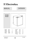
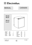
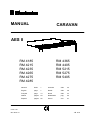
MANUAL
CARAVAN
AES II
RM 4185
RM 4215
RM 4235
RM 4265
RM 4275
RM 4285
RM 4365
RM 4405
RM 5215
RM 5275
RM 5405
Deutsch
Seite
1
Svenska
sida
32
English
page
7
Dansk
side
38
Français
page
14
Norsk
side
44
Italiano
pagina
20
Nederlands
pag.
50
Español
pagina
26
Suomi
sivu
57
C 40/ 110
821 2647.12
T.B. 8 '97
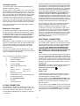
OPERATING AND INSTALLATION INSTRUCTIONS
FOR ELECTROLUX REFRIGERATORS
INTRODUCTION
CONTENTS
We are pleased that you have chosen this refrigerator and
hope you will derive much satisfaction from using it, but first
a few well-meant words of advice:
OPERATING INSTRUCTIONS . . . . . . . . . . . . . . . . . . . . . 8
CONTROLS . . . . . . . . . . . . . . . . . . . . . . . . . . . . . . . . . . . . . 8
It is important to read through these instructions carefully
before using the refrigerator.
STARTING THE REFRIGERATOR . . . . . . . . . . . . . 8
To ensure good refrigeration and economical operation, the
refrigerator must be installed and used as described in
these instructions.
SWITCHING BETWEEN ENERGY SOURCES . 8
The refrigerator is designed for building-in to leisure
vehicles such as caravans or motorhomes.
REGULATING THE TEMPERATURE. . . . . . . . . . . 8
WINTER OPERATION . . . . . . . . . . . . . . . . . . . . . . . . . . 8
TRAVEL CATCH . . . . . . . . . . . . . . . . . . . . . . . . . . . . . . . . 9
The appliance is certified according to the EU-Gas-Directive
90/396/EEC.
FOOD STORAGE . . . . . . . . . . . . . . . . . . . . . . . . . . . . . . . 9
This refrigerator comes with an
ICE-MAKING . . . . . . . . . . . . . . . . . . . . . . . . . . . . . . . . . . . . 9
Automatic Energy Selector
DEFROSTING . . . . . . . . . . . . . . . . . . . . . . . . . . . . . . . . . . . 9
which controls operation and energy supply. To put the
refrigerator in operation, just trip the main switch - AES
manages the rest.
CLEANING THE REFRIGERATOR . . . . . . . . . . . . . 9
TURNING OFF THE REFRIGERATOR . . . . . . . . . 9
TRANSIT DAMAGE
IF THE `FRIDGE FAILS TO WORK. . . . . . . . . . . . . 9
Inspect the refrigerator for damage. Transit damage must
be reported to whoever is responsible for delivery not later
than seven days after the refrigerator was delivered.
GUARANTEE AND SERVICE. . . . . . . . . . . . . . . . . 10
MAINTENANCE . . . . . . . . . . . . . . . . . . . . . . . . . . . . . . . 10
DATA PLATE
INSTALLATION INSTRUCTIONS . . . . . . . . . . . . . . . . 10
Check the data plate, inside the refrigerator, to ensure that
you have received the right model.
REPOSITIONING THE HINGES . . . . . . . . . . . . . . 10
INSTALLATION /BUILDING-IN . . . . . . . . . . . . . . . 10
The data plate contains e. g. the following details:
VENTILATION OF THE UNIT . . . . . . . . . . . . . . . . . 10
Model designation RM . . . . . . . . . . . . . . . . . . . . .
Product number . . . . . . . . . . . . . . . . . . . . . . . . . . .
Serial number . . . . . . . . . . . . . . . . . . . . . . . . . . . . .
LP GAS CONNECTION . . . . . . . . . . . . . . . . . . . . . . . 11
ELECTRICAL CONNECTION . . . . . . . . . . . . . . . . . 11
Since these details will be needed if you have to contact
service personnel, it is a good idea to make a note of them
here.
INTERIOR LIGHT -BULB -CHANGE. . . . . . . . . . 12
TECHNICAL DATA . . . . . . . . . . . . . . . . . . . . . . . . . . . 13
7
Then push button (A) to "ON" again. After 10 sec. AES will
repeat the ignition sequence. When the AES LED (C) again
starts flashing red after 30 sec, the trouble persists (air in
the line, no gas?). Switch (A) briefly off and then on again. It
might be necessary to repeat this operation 3-4 times if the
tubing contains air (after changing gas bottles, repairs etc).
If this does not help, you should consult a service technician.
OPERATING INSTRUCTIONS
CONTROLS
This refrigerator is equipped with an Automatic Energy
Selector (AES) which controls its operation and energy
supply.
The system selects the available energy source in the order
230/240 V – 12 V – LP gas. No manual operation is necessary for selecting the energy source.
230 V Operation
When a mains connection is available, AES will select this.
Please note, that even being in AC mode, 12 V DC is neccessary for the internal supply of the electronics.
The control panel is shown in fig. 3.
The refrigerator is set into operation by pushing button (A)
(main switch). The AES LED (C) lights green showing: AES
system working. Push- button (B) is used for setting the
electronic thermostat. The thermostat LEDs (D) show the
choosen temperature position. When there is a demand for
refrigeration, AES will connect the most favourable of the
available energy sources.
12 V operation
AES will select the 12 V mode of operation only when the
vehicle engine is running (detected by the alternator connection of the fridge).
Note: 12 V must always be available to supply the electronics.
SWITCHING BETWEEN ENERGY
SOURCES
STARTING THE REFRIGERATOR
When switching from one energy source to another, there
are some delays implemented in the AES system.
All references are to fig. 3.
The 15 min. delay between switching off the engine and
starting gas mode is intended to to delay the starting of gas
mode e.g. when stopping at a filling station.
LP Gas operation
Nevertheless it is not allowed to have a naked
flame at a gas filling station. If you are not sure, that
your stop is shorter than 15 min., you are advised to
switch off the main switch (A), fig. 3, when stopping
at a filling station.
AES will select LP gas operation under the following
conditions:
● No AC (230 V) available
● Engine not running (no high current at 12 VDC available)
● AC available but too low
● Engine running but DC supply too low
Undervoltage operation
The AES system is designed to guarantee the maximum
cooling efficiency under any circumstances. Therefore, the
system monitores continously the voltage level while being
in either 12 V DC or 230 V AC mode. If the voltage is too
low, the system switches to Gas mode shown by the yellow
LED (E in fig.3). The system stays in Gas mode, until the
electrial supply voltage has recovered to the normal level.
(condition three and four are briefly described in item
Undervoltage operation)
When the system chooses LP Gas operation, the flame
failure device is automatically opened, allowing the gas to
flow to the burner. At the same time, the electronic igniter is
energized.
WINTER OPERATION
Please check that the ventilation grilles or the flue outlet are
not blocked by snow, leaves etc.
After initial installation, servicing, or changing gas cylinders
etc., the gas pipes may contain some air which should be
allowed to escape by briefly turning on the refrigerator or
other appliances. This will ensure that the flame lights
immediately.
ELECTROLUX ventilation grilles A 1620 (fig. 2), can be
fitted with winter covers, model WA 120, to protect the
cooling unit against cold air. The covers may be fitted when
the outside temperature is below approx. 10°C and should
be fitted when the temperature is below the freezing point.
If the flame goes out (by gust of wind etc), the igniter is
immediately activated and reignites the gas.
We suggest that you fit the winter covers also in the case
that the vehicle is laid up during the winter months.
Note: the control electronics and the igniter must have a
DC (battery) supply to operate.
REGULATING THE TEMPERATURE
Gas trouble-shooting
The position number refers to fig. 3.
If the AES LED (C) is flashing red, the system was not able
to start or continue gas operation. Set the switch (A) to 0
and check that there is enough gas in the gas bottle, that its
valve is open and that any valves in the gas line to the
refrigerator are open.
It will take a few hours for the refrigerator to reach normal
operating temperature. So we suggest you start it well in
advance of a trip and if possible store it with precooled
foodstuffs.
The temperature of the refrigerator main compartment is set
8
for all three sources of energy, by means of the thermostat
knob (B). After turning on the refrigeratior the system automatically chooses the mid- position. With some experience
you will soon find a suitable setting. This normally does not
need resetting because the same thermostat controls the
main compartment temperature for any of the three sources
of energy.
receptacle at the rear of the refrigerator where it
evaporates. Defrost water in the freezer compartment
should be mopped up with a cloth.
When the ice has melted, wipe the refrigerator dry and
restart it. Place the food items back inside but wait until the
refrigerator is cold before making ice cubes.
CLEANING THE REFRIGERATOR
TRAVEL CATCH
Clean the inside of the refrigerator regularly to keep it fresh
and hygienic.
Make sure that the travel catch is engaged when the
caravan is on the move, (fig. 1).
Soak a cloth in a solution consisting of a teaspoon of bicarbonate of soda to half a litre of warm water. Wring out the
cloth and use it to clean the interior of the refrigerator and
its fittings.
The travel catch at the top of the door can be set in two
different positions. In one position the door is held tightly
shut. In the other position the door is secured ajar so that
the refrigerator can be aired when not in use.
Never use detergents, scouring powder, strongly scented
products or wax polish to clean the interior of the refrigerator as they may damage the surfaces and leave a strong
odour.
FOOD STORAGE
Always keep food in closed containers. Never put hot food
in the refrigerator; allow it to cool first.
The exterior of the refrigerator should be wiped clean now
and again, using a damp cloth and a small quantity of detergent. But not the door gasket, which should only be cleaned
with soap and water and then thoroughly dried.
Never keep items in the refrigerator which might give
off flammable gases.
The 2-star (**) frozen food compartment is intended for the
storage of frozen food and for making ice. It is not suitable
for freezing items of food.
The cooling unit behind the refrigerator should be cleaned
with a brush from time to time, but make sure that the
re-frigerator is switched off when doing this.
Never put bottles or cans of fizzy drinks in the frozen food
storage compartment as they may burst when freezing. Also
don't give children ice lollies straight from the frozen food as
they could cause frost burns.
TURNING OFF THE REFRIGERATOR
If the refrigerator is not to be used for some time:
1. Set the switch (A), fig. 3, to "OFF".
2. Shut off any on-board valve in the gas line to the refrigerator.
3. Empty the refrigerator. Defrost and clean it as described
earlier. Leave the doors of the refrigerator and the frozen
food compartment ajar. Use the travel catch to hold in
this position.
4. When the vehicle is laid up for a long period of time (e.g.
during the winter months), we suggest fitting the winter
covers WA 120, fig. 2, onto the vent grills.
Most kinds of frozen food can be stored in the frozen food
compartment for about a month. This period of time may
vary, however, and it is important to follow the instructions
on the individual packets.
ICE MAKING
It is practical to make ice during the night – then the refrigerator is less demanded and the cooling unit has more reserves. Fill the ice tray to just below the brim with drinking
water and place it on the freezer shelf.
To speed up the ice making, one can spill one or two
spoonfuls of water on the freezer shelf to improve the contact to the ice tray. If you have more than one ice tray it is a
good idea to make ice in advance and save the frozen trays
in the frozen food compartment.
IF THE `FRIDGE FAILS TO WORK
Check the following points before calling a service technician:
1. that the green AES LED goes on, when the switch (A) is
set to "ON" (12 V must be available).
2. when mains are connected but the fridge stays in gas
oeration: Is the refrigerator correctly connected and is the
fuse intact?
3. in transit, if the fridge does not operate in DC mode: Is
the alternator (D+) connection made correctly ?
4. if the AES LED flashes red: see chapter Gas TroubleShooting.
DEFROSTING
Frost will gradually accumulate on the refrigerating surfaces.
It must not be allowed to grow too thick as it acts as an
insulator and adversely affects refrigerator performance.
Check the formation of frost regularly every week and when
it gets about 3 mm thick, defrost the refrigerator.
To defrost the `fridge, turn it off and remove the ice tray and
all food items. Warning: normally the temperature of items
of fozen foods would rise unduly during defrosting and so
they should be consumed within 24 h or discarded.
If the refrigerator is not cold enough it may be because:
1. The ventilation is inadequate owing to reduced area of
the ventilation passages (partial blockage of grilles from
wire mesh etc).
2. The evaporator is frosted up.
3. The temperature control setting is incorrect.
4. The gas pressure is incorrect – check the pressure regulator at the gas container.
Do not try to accelerate defrosting by using any kind of
heating appliance, as this might damage the plastic surfaces of the refrigerator. Neither should any sharp objects be
used to scrape off the ice.
The defrost water runs from a collector channel to a
9
5. The ambient temperature is too high.
6. To much food is loaded at one time.
7. The door is not properly closed or the magnetic sealing
strip is defective.
The refrigerator must not be exposed to radiated heat from
hot objects (e.g. below a cooker without proper heat shielding).
Excessive heat irradiation impairs performance and leads to
increased energy consumption. For this reason the refrigerator should be installed if possible not at the entrance side
of the vehicle – normally orientated south and often with an
awning which would impair the dispersion of heat and combustion gases from the ventilation openings.
If the refrigerator still does not work properly, call a service
technician.
The sealed cooling system must not be opened, since it
is under high pressure.
GUARANTEE AND SERVICE
It is not a good practice to install the refrigerator so that the
vent openings are covered by the vehicle's entrance door
when this is open. This would reduce the ventilation air flow
to the cooling unit and reduce refrigeration performance.
The refrigerator is guaranteed for one full year on condition
that it is used in a correct manner and in accordance with
these operating and installation instructions.
It is also embraced by a European guarantee as described
in the brochure supplied with the refrigerator.
The enclosure
The refrigerator must be installed in an enclosure, the
dimensions of which are shown in TECHNICAL DATA.
Service and spare parts are obtainable from your dealer or
Electrolux – consult the telephone directory.
The bottom of the enclosure must be horizontal and even
so that the refrigerator can be easily pushed into place. It
must be sturdy enough to carry the weight of the `fridge.
MAINTENANCE
Concerning gas- and electric installations, only authorized
experts are allowed to carry out maintenance and repair
works. Besides, it is recommendable to contact an authorized service if it comes to repair works.
Battens should be installed at the enclosure and fitted with
sealing strips, as shown in fig. 5. (Other suggestions for a
sealed installation are shown in a folder which can be
obtained from Electrolux).
According to the valid regulations G607 of DVGW, the gas
installation as well as the connect flue oulets are to be
checked every two years by an expert (this has to be
arranged by the person responsible).
Slide in the refrigerator until it is flush with the front of the
recess. There must be 10-20 mm free space behind the
refrigerator.
Four fasteners are fitted in plastic bushings in the side walls
of the fridge, fig. 8. They are used for securing the refrigerator in the enclosure.
SOME USEFUL HINTS
Make sure that:
● Defrosting is carried out periodically.
● The refrigerator is clean and dry with the door left open
when it is not to be used for some time.
● Liquids or items with a strong odour are well packaged.
● The ventilation openings are unobstructed.
● The door is secured by means of the travel catch when
the caravan is on the move.
The side walls of the enclosure and/or any wooden braces
installed to hold the refrigerator must be dimensioned to
seat the screws securely, also considering the forces due to
the movement of the vehicle.
With the refrigerator in place, drive the screws through the
bushings in the lining of the refrigerator into the walls of the
enclosure. There must not be more than 3 mm of clearance
between refrigerator and enclosure on each side. If necessary, wooden strips or similar should be fitted.
INSTALLATION INSTRUCTIONS
Note: This is the only approved means of securing the
refrigerator to the enclosure and to the vehicle. Fasteners
penetrating other parts of the insulation (PU) foam of the
refrigerator might damage components like electric wiring
etc.
REPOSITIONING THE HINGES
The door hinges can be moved to the opposite side in the
following way:
● Unscrew the upper hinge pin, taking care not to lose the
set of washers and bushes.
● Lift the door from the lower hinge pin.
● Unscrew the pin and mount it on the opposite side hinge.
● Unscrew the travel catch and mount it on the opposite
side.
● Fit the door on the pin and reassemble the pin with
washers and bushes in its new place.
● Check that the door closes properly and seals all round.
VENTILATION OF THE UNIT
At high ambient temperatures the refrigeration unit will only
perform adequately when properly ventilated.
The refrigeration unit is ventilated via two openings in the
wall of the caravan (see fig. 6). Fresh air enters through the
lower opening and warm air is discharged through the upper
one.
Locate the lower opening immediately above the floor of the
recess, and the upper one as high as possible above the
condenser (C) of the refrigeration unit, at least as shown in
fig. 7b but preferably as shown in fig. 7a.
INSTALLATION/BUILDING-IN
The refrigerator is intended for installation in a caravan or
motorhome, and the description relates to this application.
10
The gas installation should only be carried out by an authorized gas fitter. It is recommended that the gas pipe feeding
the refrigerator is so arranged that it is possible to turn off
the supply of the refrigerator. It must be of a type approved
for use with continuously operating bottled-gas appliances,
and have threaded compression connections throughout.
PUSH-ON CONNECTIONS MUST NOT BE USED (We do
not approve the use of "rubber" type flexible tubing for
connecting permanently operating appliances of this type in
the United Kingdom). All connectors etc. should be of a type
specifically designed for the type and diameter of the connection pipe used, and screwed joints should be sealed with
a joining compound approved for use with bottled gas.
Ventilation grilles
The openings in the caravan wall must be fitted with the
Electrolux Ventilation systems.
Fitting the grilles, model A 1620, fig.2, which were specially developed by Electrolux for this purpose. It is a good
idea to install the frame R 1640 (B in fig. 7a) at the same
time. Then the grilles can be easily removed, which permits
inspection and small repairs to be carried out without the
necessity for removing the refrigerator from the recess.
If there is no outer grille at floor level where leaking gas can
escape, a 40 mm hole to the outside should be made in the
floor of the recess to drain any unburnt gas to the outside.
The gas supply pipe should be connected to the gas inlet
pipe on the right hand side of the gas control valve by
means of a suitable threaded compression coupling.
Fit the hole with wire mesh and an angled plate to protect
from stones, mud etc.
In making the connection to the refrigerator, a gas cock of
an approved type for use on LPG must be incorporated in
the supply line in a position which is readily accessible to
the user. For eventual servicing purposes, the union should
be on the outlet side of the cock and the pipework should
be positioned so as not to prevent the refrigerator from
being readily withdrawn.
Removal of flue gases
The ventilation passage at the rear of the recess, between
the outer wall of the vehicle and the refrigerator (fig. 7a/b),
is sealed off against the living space, and so cold draughts
are excluded (winter camping) and no flue gases can
penetrate into the vehicle. Thus a special flue outlet is no
longer necessary – the gases are dispersed through the
upper vent grille.
ELECTRICAL CONNECTION
The electrical installation must be carried out in a proper
and durable manner, taking into account all relevant regulations and codes of practice. For mains voltage operation, it
is important that the circuit to and in the caravan is effectively earthed. ALL MAINS VOLTAGE WIRING IN THE
CARAVAN MUST BE INSTALLED IN ACCORDANCE
WITH CURRENT I.E.E. REGULATIONS INCLUDING THE
USE OF AN OUTLET AND COUPLER TO BS4343/CEE17.
Note: With this mode of installation the same type of grilles
(without an integrated flue outlet), should be installed at the
upper as well as at the lower vent opening. The angled
T-piece for the flue tube (when delivered) should not be
used in this case.
The top of the enclosure above the flue tube (I), fig. 7a/b,
should be covered with aluminum sheet metal, as indicated
in (B), to facilitate the heat dispersion.
For connection to a 230 V electricity supply, the refrigerator
has a 3-core mains lead which is intended for connection to
a properly earthed plug and socket outlet. The socket outlet
should be fitted in the caravan in a position readily accessible to the user, within reach of the mains lead. In the United
Kingdom, the plug and socket outlet should be of the nonreversible type.
In fig. 7 the letters have the following meaning:
A.
Frame R 1640 for the grilles
B.
Aluminum cladding
C.
Condenser of cooling unit
D.
Vent grill A 1620
E.
Sealing profile (optional extra)
IMPORTANT: The wires in the mains lead of this appliance
are coloured in accordance with the following code:
Width:
GREEN-AND-YELLOW = EARTH
525 mm, part. nr.
295 1147-00
BLUE = NEUTRAL
486 mm
295 1147-10
BROWN = LIVE
F.
Refrigerator rear wall
G.
Wooden batten 10 x 20 mm (see also fig. 5)
H.
Height of the enclosure
(see TECHNICAL DATA)
I.
Flue tube
K
T-piece ("lazy tee")
As the colours of the wires may not correspond with the
coloured markings identifying the terminals in your plug, in
the United Kingdom, proceed as follows:
The wire which is coloured GREEN-AND-YELLOW must be
connected to the terminal in the plug which is marked with
the letter E or by the earth symbol or coloured green or
green-and-yellow.
The wire which is coloured BLUE must be connected to the
terminal which is marked with the letter N or coloured black.
LP GAS CONNECTION
The refrigerator is designed for operation on LP gas, the
pressure of which must be 28 mbar for Butane and 37 mbar
for Propane. Check that this is stated on the data plate.
The wire which is coloured BROWN must be connected to
the terminal which is marked with the letter L or coloured
red.
The refrigerator is not designed for operation on town gas
or natural gas.
11
WARNING! THIS APPLIANCE MUST BE EARTHED.
Cross- sections
In the United Kingdom, the plug or circuit to the refrigerator
must be fitted with a fuse not greater than 5 amps. If a 13
amp.(B.S.1363) fused plug is used, it should be fitted with a
3 amp. fuse. In other countries, the fuse rating will depend
upon the voltage and local practice.
The D+ (alternator) connection does not carry high current,
therefore it is no need to use a high cross- section cable.
For the 12 V (+) and (-) leads, we recommend a 6 mm2
wire. Up to a length a 5 m, 4 mm2 might be sufficient as
well.
230 V Supplies.
Please consult a specialist, if you are not familiar with
the 12 V electrical system in your motorhome.
Check that the voltage stated on the data plate is the same
as the mains voltage in use (230 V).
Electrical leads must be routed and secured so that
they cannot come into contact with hot or sharp parts
of the refrigerator.
INTERIOR LIGHT- BULB- CHANCE
If a bulb has to be replaced, proceed as follows:
1. Remove cover of the lamp.
2. Put a small screw driver between the case of the lamp
and the lamp cover and remove lamp cover.
3. Turn bulb socle for 90 degrees and remove it.
4. Put in new buld and turn it again for 90 degrees.
5. Install lamp cover on the lamp case.
12 V and "D+" Connection
The 12 V connection of the refrigerator is shown in fig. 10.
The (+12V) and (-) pole have to be connected directly to the
auxiliary (house) battery. Do not use the chassis for the
return lead. The battery cable must not be connected to a
voltage controller or similar device as the AES itself monitors the battery voltage. A relay cutting out 12 V operation
when the ignition key is turned off, is not recommended.
All splices should be screwed or soldered to keep voltage
drop to a minimum. The positive conductor must be protected by a 16 A fuse.
The connection D+ (alternator) has to be connected to
the corresponding outlet of the vehicles electrical
system.
12
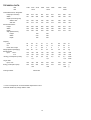
TECHNICAL DATA
RM
RM
Overall dimensions, refrigerator
Height (incl.controls)
Width
Depth (incl.cooling unit)
without door
with door
Recess dimensions
Height
Width
Depth
Step (wheel house)
Height
Width
Depth
Capacity
gross
net
frozen food compt.
Weight (without packaging)
Electrical data
Input
230 V
12 V
**Energy consumption (in 24h)
LP gas data
Input, max.
Energy consumption (24h)
Cooling medium
4185
4215 4235
*5215
4265
4275
*5275
4285
4365
4405
5405*
595
401
618
486
821
486
821
486
821
486
821
486
821
486
805
525
mm
mm
427
461
435
474
435
474
435
474
495
534
435
474
495
533
495
533
mm
mm
597
405
442
620
490
450
825
490
450
825
490
450
825
490
505
825
490
450
825
490
510
810
530
510
mm
mm
mm
220
490
225
220
490
225
40
36
16,5
60
51
6
20
70
60
5
23
70
60
6,5
23
77
72
7
23
81
77
5
23
89
83
7
26
103
92
12
30
lit
lit
lit
kg
105
100
1,9
105
100
2,3
*2,1
105
100
2,3
125
120
2,5
125
120
2,5
*2,3
125
120
2,5
135
130
2,7
135
130
2,7
*2,3
watt
watt
kWh
kWh
186
240
186
240
*210
186
240
232
270
232
270
*230
232
270
232
270
232
270
*230
watt
g
g
Ammoniak
** Power consumption at an anual ambient temperature of 25°C.
Technical details may change without notice.
13