1
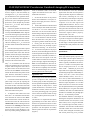
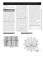
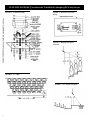
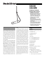
CH230/
CH230W
Condenser Cardioid
Hanging Microphones
• Available in black or white
• Braided cable shield maintains
horizontal aiming, even when
temperature and humidity vary
• Preamp mounts in standard
electrical boxes
• Steel preamp shield gives high
resistance to electrical noise and
rf interference
• Hum-bucking output transformer
cuts hum by more than 20 dB
• Screw-type output terminals are
reliable over the long term
quality.
Description and Application
The CH230 and CH230W hanging microphones, utilize back-electret condenser technology to provide an extended, flat frequency
response with a controlled cardioid polar pattern for high-quality sound reinforcement.
The CH230 and CH230W were specifically
designed to mic choirs, instrumental and
vocal groups, and live theater. The size and
color (black/white) of the transducer and
cable allow the microphone to blend in with
the surroundings.
The CH230’s low self noise and high output
signal level combine to produce an excellent signal-to-noise ratio. Exceptionally
high sensitivity, a uniform cardioid polar
response, and smooth frequency response
make the CH230 ideally suited for distant
sound pick-up. The cardioid polar response
is precisely controlled and is highly effective in suppressing feedback without coloration of sound. Additionally, unwanted lowfrequency noise such as the rumble from airmoving equipment can be reduced with the
use of a switchable high-pass filter. The
filter’s corner frequency (75 Hz) is low
enough to have essentially no effect on voice
The CH230 and CH230W are easily aimed
at the performance with the supplied steel
wire hanger and holding nut. The wire hanger
attached to the microphone element and
cable can be bent to aim the microphone in
the vertical plane. The horizontal positioning of the microphone is accomplished by
rotating the element and locking the position with the nut (detailed description later).
This allows the microphone to be accurately
positioned over a choir, stage or orchestra.
The CH230 and CH230W are furnished with
30 feet of black (CH230) or white
(CH230W) miniature braided shielded cable.
The design of the cable ensures the
microphone’s horizontal position will be held
stable without the need of fish-line tethering.
The CH230’s electronics module and mounting hardware allow quick assembly and
mounting to a standard electrical switch box
or four-inch electrical box. Figure 3 illustrates the assembly for either box style. Connecting a mixer to the electronics module is
through the output terminal block. Power is
obtained from any phantom source supplying 12 to 52 volts.
Assembly
Parts List:
1 microphone with hanger and 30 ft of cable
1 round plaster ring
1 rectangular switch cover
1 printed circuit board
1 shield box
1 strain relief
2 11/4-in. #4-40 Phillips-head screws
4 3/16-in. #4-40 Phillips-head screws
2 1/2-in. #8-32 Phillips-head screws
2 #4 split-ring washers
2 #4-40 hex-head nuts
4 threaded spacers
6 #4 fiber washers
Tools Required:
Medium-head (#2) Phillips screwdriver
Small-blade screwdriver
1
/4-in. open-end wrench
Assembly Instructions (see Figure 3):
1. Identify the type of electrical box,
switch or octagon, and select the proper
cover plate to start the assembly.
2.
Position the plate with the printed side
CH230/CH230W Condenser Cardioid Hanging Microphone
CH230/CH230W Condenser Cardioid Hanging Microphone
up with “INPUT-OUTPUT” aligned as
shown in Figure 3. Start the assembly by
inserting the two 11/4-in. screws into the upper left-hand and lower right-hand holes,
drop on the internal toothed lockwashers,
thread on the spacer and tighten against the
plate with a wrench. Repeat the procedure
for the two 3/16-in. screws. Place the fiber
washer on each spacer.
3. Position the printed circuit board with
the larger terminal block and the transformer
over the printed “OUTPUT” label. Align the
screw holes in the upper right and lower left
corners of the printed circuit board with the
two 11/4-in. screws and push down until the
board rests against the four fiber washers.
Take the remaining two 3/16-in. screws and
two fiber washers and fasten the board to the
plate.
4. Determine the length of cable required
before attaching the microphone cable to the
printed circuit board. If the cable must be
trimmed, measure the length and add three
inches. Trim the cable by removing about 1
in. of the outside jacket, then separate the
shield from the red and white wires.
Strip 1/4 in. of insulation from the red and
white wires. Push the bare wire ends of microphone cable through the center hole in
the plate and the circuit board, then insert
the wires into the “INPUT” terminal block.
Follow the label instructions printed on the
plate. With the small-blade screwdriver,
tighten the screws in the terminal block.
5. Use the strain relief to fasten the microphone cable to the plate by capturing the
cable about 1/2 in. from the front of the plate,
then orient the flats of the strain relief with
the flats of the center hole and squeeze and
push the strain relief into the center hole. The
strain relief will lock into place.
6. To attach the mixer cable to the circuit
board, trim 1/4 in. of insulation from the cable
wires and insert the wires into the “OUTPUT” terminal block. Follow the label instructions and insert the cable shield into
“SHLD GND,” and the remaining wires into
terminals 2 and 3. Warning: the CH230 and
CH230W have terminal 2 positive with a
positive pressure on the diaphragm, so be
aware of possible phasing problems if the
2
wires for terminals 2 and 3 are reversed.
Tighten the terminal block screws with a
small-blade screwdriver.
7. Set the roll-off switch to the position
desired. The rolloff filter is a two-pole, 12dB-per-octave high pass with a corner frequency of 75 Hz.
8. Position the shield box with the slotted
end over the mixer cable and the screw holes
over the two 11/4-in. screws. Push down the
shield box over the circuit board until the
shield is sitting on the plate. Inspect the mixer
cable connection for any shorts of terminals
2 or 3 to the shield box. With the wrench,
fasten the shield box to the plate with the
two split-ring washers and the two hex nuts.
9. Gently push the assembly into the
wallbox and fasten the assembly in place
with the two remaining 1/2-in. #8-32 screws.
10. To orient the microphone in the proper
direction, loosen the holding nut on the back
of the microphone and slightly twist the microphone on the wire holder (clockwise rotation moves the microphone to the left;
counterclockwise rotation moves the microphone to the right). Tighten the holding nut.
Note: for fixed installations, allow the microphone cable to hang for at least 24 hours
so the cable can completely relax and establish a set. Bend the hanger wire to position
the microphone in the vertical plane.
Application Notes
When hanging one or more microphones to
provide coverage for a choir, instrumental,
or theater group, the best microphone position for optimum sound quality and feedback
control depends on many factors—sound
system characteristics, construction of the
auditorium or theater, and the size and nature of the performing group. Two general
rules to observe for the best sound coverage
are (1) microphone position and (2) the “3to-1 rule.”
The first rule is to suspend the microphone
approximately two to three feet in front of
the first row of performers and two to three
feet higher than the heads of the last row of
performers. The microphones are usually
aimed to point at the last row of performers
(Figure 5).
The second rule, the “3-to-1 rule,” should be
applied when more than one microphone is
required, and their outputs are combined (as
with a mixer). Following the 3-to-1 rule
avoids the deep voids and dips in frequency
response that occur when two or more microphones “see” the same signal from
slightly different distances. The 3-to-1 rule
is as follows: when multiple microphones are
used, place them at least three times as far
apart as any one of them is from the nearest
sound source. Figure 6 shows a proper application of the 3-to-1 rule.
The CH230 and CH230W may also be used
to provide coverage for live theater applications (Figure 7). Most of the action occurs
at center stage, so the microphone should be
positioned above and pointed to the center
of the stage.
Architects' and Engineering
Specifications
The microphone shall be a back-electret condenser type with a frequency response of 30
Hz to 20 kHz. The microphone shall have a
cardioid polar pattern with a rear response
which is typically 20 dB below the front response at 1.0 kHz. The microphone shall
have an output power level of –21.7 dB,
where 0 dB = 1 milliwatt per pascal, and
output shall not be appreciably affected by
the following temperature and humidity extremes: –29° to 74° C (–20° to 165° F) when
relative humidity is 0-50%; –29° to 57° C (–
20° to 135° F) when relative humidity is 095%. The microphone shall have a nominal,
balanced output impedance of 150 ohms
when connected to its electronics module.
The microphone shall have a low-gloss black
finish (CH230) or a low-gloss white finish
(CH230W). The cable color shall match the
transducer. A switchable, two-pole high-pass
filter (f0 = 75 Hz) shall be provided.
The transducer shall have a wire hanger for
directing the microphone. Dimensions: the
transducer shall be 10.5 mm (0.42 in.) wide
and 41.9 mm (1.65 in.) long; the cable shall
be 9.1 m (30 ft) long and 2.6 mm (0.106 in.)
in diameter. The electronics module shall fit
into either a switch box or four-inch electrical box, with a rectangular switch-box plate
and circular plaster-ring cover provided.
CH230/CH230W Condenser Cardioid Hanging Microphone
Terminations to the electronics module shall
be terminal blocks.
The Electro-Voice model CH230 (CH230W)
is specified.
Electro-Voice products are guaranteed
against malfunction due to defects in materials or workmanship for a specified period,
as noted in the individual product-line
statement(s) below, or in the individual product data sheet or owner’s manual, beginning
with the date of original purchase. If such
malfunction occurs during the specified period, the product will be repaired or replaced
(at our option) without charge. The product
will be returned to the customer prepaid. Exclusions and Limitations: The Limited
Warranty does not apply to: (a) exterior finish or appearance; (b) certain specific items
described in the individual product-line
statement(s) below, or in the individual product data sheet or owner’s manual; (c) malfunction resulting from use or operation of
the product other than as specified in the
product data sheet or owner’s manual; (d)
malfunction resulting from misuse or abuse
of the product; or (e) malfunction occurring
FIGURE 1—Frequency Response
3
are guaranteed against malfunction from any
cause for two (2) years from the date of original purchase. In addition, the Limited Warranty for the acoustic system contained in
these microphones shall apply for the life of
the product, defined as a period of ten (10)
years from the date that the manufacture of
the specific microphone has been discontinued. Any and all active electronics incorporated in these microphones are guaranteed
against malfunction due to defects in materials or workmanship for a period of three
(3) years from the date of original purchase.
The Limited Warranty does not extend to
cables, cable connectors, or switches. Additional details are included in the Uniform
Limited Warranty statement.
For warranty repair or service information, contact the service repair department
at: 616/695-6831 or 800/685-2606.
For technical assistance, contact Technical
Support at 800/234-6831 or 616/695-6831,
M-F, 8:00 a.m. to 5:00 p.m. Eastern Standard Time.
Specifications subject to change without
notice.
FIGURE 2—Polar Response
CH230/CH230W Condenser Cardioid Hanging Microphone
Limited Warranty
at any time after repairs have been made to
the product by anyone other than ElectroVoice Service or any of its authorized service representatives. Obtaining Warranty
Service: To obtain warranty service, a customer must deliver the product, prepaid, to
Electro-Voice Service or any of its authorized service representatives together with
proof of purchase of the product in the form
of a bill of sale or receipted invoice. A list of
authorized service representatives is available from Electro-Voice Service at 600 Cecil
Street, Buchanan, MI 49107 (800/234-6831
or FAX 616/695-4743). Incidental and
Consequential Damages Excluded: Product repair or replacement and return to the
customer are the only remedies provided to
the customer. Electro-Voice shall not be liable for any incidental or consequential damages including, without limitation, injury to
persons or property or loss of use. Some
states do not allow the exclusion or limitation of incidental or consequential damages
so the above limitation or exclusion may not
apply to you. Other Rights: This warranty
gives you specific legal rights, and you may
also have other rights which vary from state
to state. Electro-Voice Wired Microphones
CH230/CH230W Condenser Cardioid Hanging Microphone
CH230/CH230W Condenser Cardioid Hanging Microphone
FIGURE 3—Assembly Drawing
FIGURE 4—Electronics Board and
Wiring
FIGURE 5—Hanging Microphone
Placement
FIGURE 6—3-to-1 Rule
FIGURE 7—Live Theater Placement
44
CH230/CH230W Condenser Cardioid Hanging Microphone
Specifications
Generation Element:
Condenser, back electret
30 Hz to 20,000 Hz
Polar Pattern (see Figure 2):
Cardioid
Sensitivity,
Open Circuit Voltage, 1 kHz:
30 mV/pascal
Power Level, 1 kHz (0 dB = 1 mW/pascal):
–21.7 dB
Clipping Level (1% THD):
127 dB SPL
Equivalent Noise:
22 dB SPL A weighted
Dynamic Range:
105 dB
Output Impedance, 1 kHz:
150 ohms
55
12 to 52 V dc phantom supply
Current Consumption:
2.1 mA
Switchable High-Pass Filter,
Corner Frequency:
75 Hz
Slope:
12 dB per octave
Polarity:
A positive pressure on the diaphragm
produces a positive voltage on output
pin 2
Color,
CH230: Nonreflecting black
CH230W: White
Environmental Conditions,
Relative Humidity 0–50%:
–29° to 74° C (–20° to 165° F)
Relative Humidity 0–95%:
–29° to 57° C (–25° to 135° F)
Dimensions,
Transducer:
10.5 mm (0.4 in.) diameter,
41.9 mm (1.65 in.) long
Microphone Cable:
9.1 m (30 ft) long
Electronics Module:
67.3 mm (2.65 in.) long,
40.6 mm (1.6 in.) wide,
30.5 mm (1.2 in.) high
Net Weight:
332 grams (11.7 oz)
Shipping Weight:
555 grams (19.6 oz)
CH230/CH230W Condenser Cardioid Hanging Microphone
Frequency Response (see Figure 1):
Power Requirements:
CH230/CH230W Condenser Cardioid Hanging Microphone
CH230/CH230W Condenser Cardioid Hanging Microphone
600 Cecil Street, Buchanan, MI 49107
616/695-6831, 616/695-1304 Fax
MICROPHONES–Condenser Cardioid
6
©EVI Audio 1999 • Litho in U.S.A.
Part Number 532021 — 9941