1
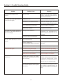
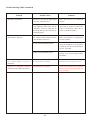
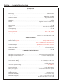
Operating Instructions
RE-2
User Guide
Table of Contents
Quick Set-Up. . . . . . . . . . . . . . . . . . . . . . . . . . . . . . . . . . . . . . . . . . . . . . . . . . . . . . . . . . . . . . . . . . . . . . . . . . . . . . . . . . . . 1
System Description . . . . . . . . . . . . . . . . . . . . . . . . . . . . . . . . . . . . . . . . . . . . . . . . . . . . . . . . . . . . . . . . . . . . . . . . . . . . . . . 1
Detailed Components Description . . . . . . . . . . . . . . . . . . . . . . . . . . . . . . . . . . . . . . . . . . . . . . . . . . . . . . . . . . . . . . . . . . 2
Receiver Setup and Operation. . . . . . . . . . . . . . . . . . . . . . . . . . . . . . . . . . . . . . . . . . . . . . . . . . . . . . . . . . . . . . . . . . . . 2
Receiver Push-Button Reference Sheet. . . . . . . . . . . . . . . . . . . . . . . . . . . . . . . . . . . . . . . . . . . . . . . . . . . . . . . . . . . . . 3
Handheld Transmitter . . . . . . . . . . . . . . . . . . . . . . . . . . . . . . . . . . . . . . . . . . . . . . . . . . . . . . . . . . . . . . . . . . . . . . . . . . 4
Bodypack Transmitter . . . . . . . . . . . . . . . . . . . . . . . . . . . . . . . . . . . . . . . . . . . . . . . . . . . . . . . . . . . . . . . . . . . . . . . . . . 6
Approval Information . . . . . . . . . . . . . . . . . . . . . . . . . . . . . . . . . . . . . . . . . . . . . . . . . . . . . . . . . . . . . . . . . . . . . . . . . . . . 6
Display Screens and Functions . . . . . . . . . . . . . . . . . . . . . . . . . . . . . . . . . . . . . . . . . . . . . . . . . . . . . . . . . . . . . . . . . . . . . 7
Receiver Main Operating Screen . . . . . . . . . . . . . . . . . . . . . . . . . . . . . . . . . . . . . . . . . . . . . . . . . . . . . . . . . . . . . . . . . 7
Receiver Controls and Functions . . . . . . . . . . . . . . . . . . . . . . . . . . . . . . . . . . . . . . . . . . . . . . . . . . . . . . . . . . . . . . . . . 7
Transmitter Displays and Controls . . . . . . . . . . . . . . . . . . . . . . . . . . . . . . . . . . . . . . . . . . . . . . . . . . . . . . . . . . . . . . . . 7
Transmitter On/Off Lock-out . . . . . . . . . . . . . . . . . . . . . . . . . . . . . . . . . . . . . . . . . . . . . . . . . . . . . . . . . . . . . . . . . . . . 8
Guidelines and Recommendations for Best Performance . . . . . . . . . . . . . . . . . . . . . . . . . . . . . . . . . . . . . . . . . . . . . . . 8
Trouble Shooting Guide . . . . . . . . . . . . . . . . . . . . . . . . . . . . . . . . . . . . . . . . . . . . . . . . . . . . . . . . . . . . . . . . . . . . . . . . . . . 9
Technical Specifications . . . . . . . . . . . . . . . . . . . . . . . . . . . . . . . . . . . . . . . . . . . . . . . . . . . . . . . . . . . . . . . . . . . . . . . . . . 11
Accessories and Parts. . . . . . . . . . . . . . . . . . . . . . . . . . . . . . . . . . . . . . . . . . . . . . . . . . . . . . . . . . . . . . . . . . . . . . . . . . . . 14
Factory Service/Warranty (Limited) . . . . . . . . . . . . . . . . . . . . . . . . . . . . . . . . . . . . . . . . . . . . . . . . . . . . . . . . . . . . . . . 15
-i-
Section 1 - Quick Set-Up
5. Use the up and down arrows to change the Group number
to match the Group number displayed on the receiver.
Press SET and the Channel Number will flash.
Quick Set-up: Receiver
1. Do not connect the receiver to any other equipment yet!
2. Connect the two antennas to the receiver.
6. Use the up and down arrow buttons to change the Channel
to match the receiver. Press Set and nothing will be flashing. The channel is now set.
3. Plug the power supply into the back of the receiver and
into an outlet
4. Press the POWER switch. Display will light up.
5. Press and hold the SET button until ClearScan
and starts flashing on the right side of the screen.
TM
7. If you are using a bodypack transmitter, plug the microphone into the transmitter connector. If using a guitar, turn
the transmitter off and wait until display is blank. Hold
SET down and turn the transmitter on. A guitar symbol
should appear on the display. Plug the cord into the transmitter and guitar.
shows
6. When ClearScanTM stops flashing, the receiver will automatically set itself and display the clearest group and channel.
7. If you are using a guitar, turn off the receiver. Press and
hold SET while you turn the receiver on. A guitar symbol
will appear in the display to indicate instrument mode.
Transmitter “Quick Set-up” is complete.
Quick set-up: System Operation
1. With the transmitter and receiver on, monitor the display
screen. Note that the RF (1-100) Bar graph should indicate
near the 100 mark. The AF Bar should show very little, if
any, indication until you talk or sing into the microphone.
Adjust the transmitter gain control if necessary to cause
the AF Bar Graph to peak near -6 to -3 but not over +3 for
best performance.
8. Turn the receiver off and connect the mixer or other audio
system to the receiver XLR Connector or the ¼ inch Line
Level Jack.
9. Set the audio mixer or other system input level to minimum.
10. Press the Power switch button in again.
2. Set the mixer/amp gain.
Receiver “Quick Set-up” is complete.
3. Talk or sing into the microphone or play the guitar at a
normal volume. You should hear audio coming out of the
system.
Quick set-up: Transmitter
1. With the Power Switch on the transmitter OFF, install a
fresh alkaline battery into the transmitter.
4. If using the unbalanced 1/4" output, you may have to adjust the gain (via the control next to the connector on the
back panel) to match the level found when singing or playing with a wired connection.
2. Place the transmitter Power Switch to the ON position.
3. The Red Battery Low Light near the display will flash on
and then off. The display will also come on and display a
group and channel.
"Quick Set-up" is now complete.
4. Press the SET button once and the Group number will
flash.
Please enjoy your RE-2 system.
Section 2 - System Description
The RE-2 Wireless Microphone system combines frequency
agility and ease of use like no other. The RE-2 transmitters
and receivers operate over a 24 MHz bandwidth in the UHF
portion of the Radio Frequency spectrum.
The high quality audio circuitry and advanced Radio Frequency (RF) signal processing offer broadcast quality signal-to-noise and audio clarity.
System Features Include:
• Advanced ClearScanTM technology for selecting the clearest
•
• Front Panel Power ON/OFF Switch
• Front Panel Software Control of Squelch settings
• Double Squelch (Amplitude and Tone) system
available channels in intermodulation free groups.
Completely programmable in 25 kHz steps for over 950
possible frequencies.
prevents
false squelch
• LCD
Displays for ease of viewing-Group, Channel, Frequency, Battery Status, Diversity Activity, Audio Meter and
RF Meter.
• Lockout feature to prevent accidental channel changes
• "Smart" battery feature in the transmitter means there is no
wrong orientation
• Patented Phase Diversity System
• Adjustable Unbalanced Line Level 1/4 inch output jack
• Balanced XLR output jack for fixed Microphone Level or
• Power Lock On feature prevents accidental turn off
• Battery level displayed at the receiver
adjustable Line Level
-1-
Section 3 - Detailed Components Description
RE-2 Receiver Controls, Connectors, and Indicators
1
2
8
3
5
Balanced
Audio
power
R
2
set
GPA CH
12u 05
EV
AU DIO
-20 -10 -6 - 3 0 +3
U.S. Patent No. 6,256,484
12-15V
AC/DC
+
1 3 10 30 100
RE-2 BAND B
Antenna
Tested to Comply
with FCC Standards
Mic
Line
Line
Level
High
Z
CANADA XXXXXX
S.N. 8A
Telex Communications, Inc.
Made in U.S.A.
3
4
Figure 1 - RE-2 Front Panel
90
Balanced
Audio
U.S. Patent No. 6,256,48
12-15V
RE-2 BAND B
AC/DC
+
Antenna
Tested to Comply
with FCC Standards
Mic
Line
Line
Level
High
Z
CANADA XXXXXX
S.N. 8A
Telex Communications, Inc.
Made in U.S.A.
Proper Antenna Orientation
6
7
Figure 2 - RE-2 Back Panel
1. Power ON/OFF
3. Display Control Buttons (Set/Up/Down)
2. Graphical Display
a. Channel Display
b. Frequency
c. Battery Strength Indicator
d. Diversity Indicator
e. RF Strength of
Signal Indicator
f. Audio Level Indicator
4. Power Connector
5. XLR Balanced Mic/Line Level Audio Output
Line Level Adjustable
6. Unbalanced Line Level Audio Output
Connector with Level Adjustment
7. TNC Antenna Input Connectors
8. Power Cord Retainer
Receiver Setup and Operation
5. Advanced ClearScan:TM This feature automates the process of finding a clear group of inter-modulation free
channels and the clearest channels within those groups.
1. Place the receiver and antennas where there is a clear line
of sight to the area where the transmitter will be used. Rotate the antennas to separate them by 90 degrees.
a. ClearScanTM, for Groups: From the main display
screen, push SET once and the Group Number will
flash. While Group is flashing, press and hold SET until ClearScanTM appears, release the set key. When the
scan is completed, the display will show the group
with the most clear channels and the Channel number
will indicate how many clear channels are in that
group. Use the UP/DOWN keys and to view other
groups and press SET to select a group. The Group
will be set and the Channel will start to flash. Select a
channel manually or use ClearScanTM for Channels.
2. Connect the power supply cord to the receiver. Plug the
power supply into an AC outlet. Turn the receiver on and
confirm that it is ON by checking the main display screen.
Caution: Please make sure the AC power supply is the correct volt age for your lo cal re quire ments before it is
plugged into the wall.
3. Manual Channel Change. Press the SET button and the
Group number will start to flash. The Up and DOWN buttons allow you to scroll through the factory set group.
When the group you desire is displayed, press SET to select that group and the Channel Number will start flashing.
Scroll to the desired channel and press SET to select. The
numbers will stop flashing and the new group and channel
are installed.
b. ClearScanTM for Channels: To scan for the clearest
channel in a group, press and hold set while the Channel is flashing until ClearScanTM appears, release the
SET button. When the scan is complete, the display
will show the clear est avail able chan nel. Use
UP/DOWN to scroll through the other available channels rank from clearest to least clear (but still available
for use, ClearScanTM will not display any channel that
can't be used). Press SET to select the channel.
4. Frequency Assignment (Outside of preset Groups and
Channels), press SET and UP at the same time and the
group and channel will go blank and the Frequency will
start flashing. Use UP/DOWN to scroll in 25 KHz steps to
the desired frequency. Press SET and the frequency will be
selected and stop flashing. Press Set and UP at the same
time to return to group and channel operation. Hint: holding in the Up or Down key will increase the speed of the
scroll. Just release and press again for fine control
c. Auto ClearScan:TM This function will find the clearest group and channel with the press of just one button.
With nothing flashing, press and hold the SET button
until ClearScan appears on the right side of the screen.
When the scan is complete, the receiver will be set to
the clearest channel in the clearest group.
-2-
NOTE: Groups x,x,x, and x are set up to work with the
other US frequency band (A and B). These groups are
listed last no matter how many open channels are available. If you are using a mix of Band A and Band B, scroll
down to these groups and use the clearest group.
Now refer ahead to transmitter setup and return to step 9
when that is completed.
9. With the transmitter on, speak into the microphone or play
the guitar. Turn up the level on the mixer or amplifier until
you are able to hear the desired signal. If no audio is present, repeat setup and refer to the troubleshooting section.
6. Change Lock-Out: By pressing and holding the UP and
DOWN arrow keys together for 3 seconds, the SET key is
disabled.To reactivate the SET key, simply press and hold
the UP and DOWN keys again for 3 seconds. This feature
can be useful when the receiver is in a location where unauthorized personnel have access to the receiver.
NOTE: If the 1/4 inch output is used, it may be necessary
to adjust the receiver output until the volume level from
the wireless system approximates the level of an equivalent wired microphone/instrument.
10. Squelch Adjustment - The squelch setting can be used to
maximize range or immunity to noise. Press and hold Up
for 3 seconds. The current squelch setting will be displayed. Adjust the squelch using the UP/DOWN keys.
Maximum squelch (9) maximizes noise immunity but limits the range. Minimum squelch (1) will maximize the range
but allow more noise to break through the squelch. Press
SET to save the new squelch setting.
7. For set up, make sure the mixer or amplifier input used for
the RE-2 is muted or turned down to a minimum level.
8. Plug an audio cable (not supplied) into the 3 pin XLR or
1/4 inch output of the RE-2.
a. NOTE: The XLR connector is the preferred connection since the output is balanced and will be more immune to noise for longer runs of cable although either
can be used with good results. If the 1/4 inch connector
is used, adjust the output level on the back panel to 12
o'clock (midway in the range) to start and adjust later if
necessary.
Receiver Push-Button Reference Sheet
Edit
n/a
Accept
Edit Group -Group will flash
??
SET
Press and hold SET
ClearScanä Group - list clear groups in order
??
SET
Group Flashing
SET
Edit Channel - Channel will flash
??
SET
Channel Flashing
Press and hold SET
ClearScanä Channel - list clear channels in order
??
SET
Nothing Flashing
Press and hold Up
Edit Squelch Setting
??
SET
Nothing Flashing
Press and hold Up & Down Edit Lock - Secure will appear
n/a
n/a
Edit Lock On
Press and hold Up & Down Return to Access Mode
n/a
n/a
Power Off
Press and hold SET
Toggle between Guitar and Voice mode
n/a
n/a
Nothing Flashing
Press SET and Up
Toggle to Frequency Mode - Freq will flash
??
SET
Frequency Flashing
Press and hold SET
ClearScanä Band - Clear Scan will flash
n/a
SET
ClearScanä Band Running
Press SET
End ClearScanä Band after next full scan
n/a
n/a
ClearScanä Band Results
n/a8
Clearest frequencies listed
??
SET
Frequency Mode
Press SET and Up
Return to Group and Channel Mode
n/a
n/a
Nothing Flashing
Press and hold Down
Display Software Revision
n/a
n/a
Display
Nothing Flashing
Status Button
Press and hold SET
Press Function Activated
Auto ClearScanä
Nothing Flashing
SET
Group Flashing
-3-
n/a
Handheld Transmitter HTU-2
2
1
3
5
7
6
SET
4
2
1
755050
8
3
9
Figure 3
Handheld Transmitter
Figure 4
Transmiter
HTU-2 Controls, Connectors, and Indicators
1. Main Display - LCD
(Channel, Frequency or Battery Level Indication)
5. Channel/Frequency Up Switch
2. Battery Low LED - Lights when battery is low
7. Microphone Gain
3. Power On/Off Switch
8. 9V Battery Holder
4. Set Switch
9. Battery Cover - Screw type.
6. Channel/Frequency Down Switch
Handheld Transmitter Setup
and Operation
5. Frequency Edit Mode - Press SET from the frequency
display screen to enter frequency edit mode. Press the Up
and Down to adjust frequency in 25 kHz increments. Holding the Up or Down buttons down will auto step the frequency; slowly at first, then quickly. You can also enter
frequency edit mode by pressing SET and UP at the same
time from either the Group and Channel or Battery status
display screens. Pressing SET and UP at the same time
form the Frequency display screen will enter Group and
Channel edit mode.
1. Insert Battery. Remove the battery compartment cover by
unscrewing it completely. Insert a 9V battery, terminal end
first into the battery compartment.
NOTE: The HTU-2 unique design allows the battery to be
inserted and used regardless of the positive and negative
terminal position.
2. With battery compartment still open, turn the unit so
you can see the display and the control panel. Turn the unit
on by sliding the power switch forward to the on position.
The battery low LED will light for a second and the display will show the Group and Channel numbers.
6. Power Lock Out - Press SET, UP, and DOWN at the same
time and hold 3 seconds to lock the power switch on. To
turn the unit off, place the power switch in the OFF position and push SET, UP, or DOWN. To remove the lock,
press SET, UP, and DOWN again at the same time and
hold 3 seconds. A one-time only ON-LOCK mode can also
be entered by quickly cycling the power switch three
times.
3. Change the group and channel numbers to match those
displayed on the receiver by pressing SET. The Group
number will flash and can be changed with the UP/DOWN
keys. Once the desired group number is showing, press
SET to select and the Channel number will flash. Select
the Channel and press SET again. The flashing will stop
and the channel is now set.
4. Other Screens: Press SET and DOWN at the same time to
display the battery level. Press SET and DOWN again to
display frequency. Press them one more time to return to
Group and Channel.
7. Set Key Lock-Out, by pressing and holding the UP and
DOWN arrow keys together for 3 seconds, the SET key is
disabled. To reactivate the SET key simply press and hold
the UP and DOWN keys again for 3 seconds.
-4-
To adjust the transmitter gain, gently insert the provided
screwdriver (or other 3/32 - 2.5 mm screwdriver) into the
adjustment hole opposite the display screen. Turn lightly
until the screwdriver tip goes into the adjustment level
control. Gently turn counterclockwise until the control
stops (the microphone output is at minimum but not off).
Slowly turn the gain control up (clockwise) while speaking/singing into the microphone and the audio meter
shows peaks around -3 dB.
8. Verify reception. With the transmitter and receiver on and
matching Group and Channel, the main receiver display
should be indicating a RF signal on the bar graph. Speak
into the microphone and the Audio Meter bar graph should
indicate audio signal presence. If the level meters do not
show reception, make sure the channels are matching and
refer to the trouble shooting section.
9. Adjustment of the transmitter audio gain - If necessary
The transmitter audio gain is factory set at the middle of
the range, which should be suitable for most applications.
For loud or soft speakers/singers, a gain adjustment may
be necessary. Have the speaker or singer use the microphone in a normal performance level voice. The Audio
Meter in the main receiver display screen should show
peaks around the -3dB level. If the meter peaks all the way
to the right or well below the -3dB level, adjust the transmitter audio gain.
NOTE: Operating with the transmitter audio gain set as
high as possible (without distortion or peaks all the way to
the right end of the meter) will result in the best performance and highest signal to noise ratio.
10. Test Performance. Go back to Section 3. Receiver Setup
and Operation - Step 9 to complete system set up and test.
5
Bodypack Transmitter - BPU-2
1
SET
9
6
Figure 6
Control View
R
755050
GP
CH
5
4
8
OFF ON BATT
Figure 5
Bodypack Transmitter
2 3
Figure 7
Top View
BPU-2 Controls, Connectors, and Indicators
1. Antenna - flexible 1/4 wave antenna
6. Display Control Buttons (Set/Up/Down)
2. Power On/Off Switch
7. Belt Clip (Removable, not shown)
3. Battery Low LED Indicator
8. 9V Battery Compartment
4. TA4 Audio Connector
9. Audio Gain Adjustment
5. LCD Display (Channel, Frequency or
Battery Level Indication)
-5-
Bodypack Transmitter Setup
and Operation
Have the speaker or singer use the microphone in a normal
performance level voice. The Audio Meter in the main receiver display screen should show peaks around the -3 dB
level. If the meter peaks all the way to the right or well below the -3 dB level, adjust the transmitter audio gain.
1. Insert Battery. Pinch the battery door tabs inward and
pull the door open. Insert a 9V battery as indicated by the
+/- in the holder.
2. With battery compartment still open, turn the unit on with
Power switch on the top panel. The battery low LED will
light for a second and the display will show the Group and
Channel numbers.
To adjust the transmitter gain, gently insert the provided
screwdriver (or other screwdriver) into the adjustment potentiometer. Gently turn counterclockwise until the control
stops (the microphone output is at minimum but not off).
Slowly turn the gain control up (clockwise) while speaking/singing into the microphone or strumming the guitar
and the audiometer shows peaks around -3 dB.
3. Change the group and channel numbers to match those
displayed on the receiver by pressing SET. The Group
number will flash and can be changed with the UP/DOWN
keys. Once the desired Group number is showing, press
SET to select and the Channel number will flash. Select
the Channel and press SET again, the flashing will stop
and the channel is now set.
NOTE: Operating with the transmitter audio gain set as
high as possible (without distortion or peaks all the way to
the right end of the meter) will result in the best performance and highest signal to noise ratio.
4. Set Key Lock-Out. By pressing and holding the UP and
DOWN arrow keys together for 3 seconds, the SET key is
disabled. To reactivate the SET key, simply press and hold
the UP and DOWN keys again for 3 seconds.
Other Screens: Press SET and DOWN at the same time to
display the battery level. Press SET and DOWN again to
display frequency. Press them one more time to return to
Group and Channel.
5. Verify reception. With the transmitter and receiver on and
matching Group and Channel, the main receiver display
should be indicating a RF signal on the bar graph. If the
level meter does not show reception, make sure the channels are matching and refer to the trouble shooting section.
8. Frequency Edit Mode - Press SET from the frequency
display screen to enter frequency edit mode. Press the Up
and Down to adjust frequency in 25 kHz increments. Holding the Up or Down buttons down will auto step the frequency; slowly at first, then quickly. You can also enter
frequency edit mode by pressing SET and UP at the same
time from either the Group and Channel or Battery status
display screens. Pressing SET and UP at the same time
form the Frequency display screen will enter Group and
Channel edit mode.
6. Attach the Microphone or Guitar.
Microphone: Plug the microphone cable into the top panel
of the BPU-2. Speak into the microphone and the Audio
Meter bar graph should indicate audio signal presence.
Guitar: Turn off the bodypack, press and hold SET while
you turn the bodypack on. A guitar symbol will appear in
the display to indicate instrument mode. Repeat the process holding SET on the receiver as it is powered up to return to voice mode. Plug in the MAC-G3 guitar cable.
Strum the guitar and the Audio Meter bar graph on the receiver should indicate audio signal presence.
9. Power Lock Out - Press and hold SET, UP, and DOWN at
the same time and hold for 3 seconds to lock the power
switch on. To turn the unit off, place the power switch in
the OFF position and push SET, UP, or DOWN. To remove the lock, press SET, UP, and DOWN again at the
same time and hold for 3 seconds. A one-time only
ON-Lock mode can also be entered by quickly cycling the
power switch three times.
7. Adjustment of the Transmitter Audio Gain - (if necessary). The transmitter audio gain is factory set at the middle of the range, which should be suitable for most
applications. For loud or soft speakers/singers, a gain adjustment may be necessary.
10. Test Performance - Go back to Section 3 - Receiver Setup
& Operation, Step 9 to complete system set up and test.
APPROVAL INFORMATION
The Electro-Voice/Telex Transmitters are Type Accepted under United States Federal Communications Commission CFR 47,
Part 74 and Industry Canada RSS123.
The Electro-Voice/Telex Receiver is approved under United States Federal Communications Commission CFR 47, Part 15 and
Industry Canada RSS210.
Licensing of Electro-Voice/Telex equipment is the users responsibility and Licensability depends upon the users classification, users application and frequency selected. Electro-Voice/Telex strongly urges the user to contact the appropriate
telecommunications authority for any desired clarification.
CAUTION: Any changes or modifications made to the above equipment could void the users authority to operate the equipment.
-6-
Section 4 - Receiver
Display Screens and Functions
4
Main Operating Screen
2
-20 -10 -5 0 +3
CLEARSCAN T M
RF
8
1 3 10 30 100
9
6
Figure 8
Main Operating Screen
Display:
5.
6.
7.
8.
9.
5
AF
1
3
1.
2.
3.
4.
7
Controls:
Group Number · · · · · · · · · · · 10 factory set
Channel Number· · · · · · · · · · 01 to 10
Frequency · · · · · · · · · · · · · · · Displayed in MegaHertz
Battery Status · · · · · · · · · · · · 100 to 0 Pct in
25 Pct steps/Flash if low
Audio VU Meter · · · · · · · · · -30 VU to + 3 VU
RF Signal Strength · · · · · · · · 1 µV to 100 µV
Antenna Diversity Status · · · left or right antenna
ClearScan™ · · · · · · · · · · · · · Indicates Scan is in progress
Guitar Symbol · · · · · · · · · · · Indicates Instrument Mode
1. Press and hold SET for 3 seconds starts Auto ClearScan™
2. Press
.
SET once, Group starts flashing, adjust with UP and
DOWN 2.a With Group flashing, press and hold SET for 3
seconds to start Group Scan
3. Press SET twice, Channel starts flashing, adjust with UP and
DOWN 3.a With Channel flashing, press and hold SET for 3
seconds to start Channel Scan
4. Press SET and UP at the same time to enter Frequency Mode
5. Press and hold UP for 3 seconds to adjust Squelch
6. Press and hold SET during power up to enter Instrument Mode
7. [UP] + [DOWN] for 3 seconds Sets/Resets Edit Lockout
Squelch Adjustment Screen
-20 -10 -5 0 +3
AF
RF
1 3 10 30 100
Figure 9
Squelch Adjustment Screen
Display:
1. Squelch Level · · · · · · · · · · · · · 1-10
Controls:
1. [UP] + [DOWN] adjust the squelch level
2. SET saves the squelch level shown and returns you
to the main screen
Transmitter Display and Controls
Display: 1. Group and Channel
2. Battery Level in Percentage
3. Frequency
Controls: 1. Press SET once, GP will flash, use UP and DOWN to adjust
2. Press SET again to accept GP, CH will flash, adjust with UP/DOWN
3. Press SET again to accept CH and channel will be installed
4. Press SET and DOWN at the same time to change display mode
5. Press SET and UP to enter Frequency Set Mode
6. Press SET and DOWN to return to the Group/Channel Mode
7. Press and hold UP and DOWN for 3 seconds to lock out SET
Figure 10
Transmitter Display and Controls
8. Press and hold UP and DOWN again to activate SET
9. Press and hold UP, DOWN, and SET to lock power (see Section 4)
10. Press and hold UP, DOWN, and SET to unlock power
-7-
Transmitter On/Off Lock-Out
There are two On/Off lockout modes available, One Time and
Everytime.
Once the working Group has been established, leave the first
transmitter on, set the next receiver Group to the working
Group and run ClearScanTM Group. This will provide the next
clearest channel in that group. Set the transmitter to match,
leave it on and repeat until all the systems are set up. If you
run out of clear channels in one group but need to set up more
systems, contact your dealer or Telex for assistance in choosing additional frequencies.
One Time: Cycle the power switch 3 times in under 3 seconds
and On-Loc will be displayed for a second and then return to
normal operation. The power switch alone will no longer turn
the unit off. To turn the unit off, put the power switch in the
off position (On-Loc will be displayed) open the battery door
and press [Set], [Up], or [Down] and the unit will power
down. The next time the unit is powered on, the power switch
will operate normally.
Potential Sources of Interference
There are many potential sources of interference for your
wireless system. Any elec tronic prod uct that con tains
dig i tal cir cuitry in clud ing dig i tal sig nal pro ces sors
(re verb/multi-effects units), electronic keyboards, digital
lighting controllers, CD and DVD players, and computers, all
emit RF energy that can adversely affect the performance of
your wireless system. It is always best to place the receiver as
far away as possible from these devices to minimize potential
problems.
Everytime Use: With the unit on and operating in the normal
mode, press and hold [Set], [Up], and [Down] for 3 seconds.
On-Loc will be displayed and the power switch alone will no
longer turn the unit off. To turn the unit off, put the power
switch in the off position, (On-Loc will be displayed), open
the battery door and press [Set], [Up], or [Down] and the unit
will power down. The next time the unit is powered on, the
On-loc function will still be on. To enable the power switch,
press and hold [Set], [Up], and [Down] for 3 seconds (On-Off
will be displayed).
Analog and Digital Television stations can also interfere with
your wireless system. The RE-2 is designed to operate over 24
MHz of RF bandwidth, which covers four TV channels. The
factory presets on the RE-2 are optimized for conditions
where one or possibly two of the four stations are covered in
your area. If three of the four stations are used in your area, it
will severely limit the number of systems that will operate together and you should be using a different band.
Guidelines and Recommendations
for Best Performance
Compatibility
The transmitter and receiver must be of the same frequency
band and set to the same group and channel in order to work
together. The RE-2 is available in two frequency bands, A and
B. The band information is available in the Group/Channel
edit screen on the receiver, the bottom label on the handheld
transmitter, and on the back panel label on the bodypack.
Battery Recommendations
Fresh 9-volt alkaline batteries form a quality manufacturer
will yield the best performance from your RE-2 transmitters.
Rechargeable 8.4-volt Ni-Cad batteries can be used but will
result in much shorter operation time.
Using Multiple Wireless Systems
If two or more RE-2 systems and/or other UHF/VHF wireless
systems are being used in the same location, proper frequency
coordination is necessary to avoid interference. All channels
in the RE-2 factory set groups are designed to work together,
so if channels from just one group are used no further
coordination is required. Contact your dealer or Telex for assistance if you are planning more systems or using the RE-2
with other wireless equipment.
When the transmitters are turned on, the red battery LED will
flash once if the battery is good. If the light does not light or
stays lit continuously, the battery is weak or dead. If the light
comes on during use, the battery is weakening and should be
replaced as soon as possible. If sound quality degrades during
use, it may be the result of a weakening battery.
Caution: The battery level indicators, on the transmitters
and receiver displays, are based on the use of alkaline batteries. Use of other battery types will result in false readings on these indicators although the battery low LED on
the transmitters will operate normally.
IMPORTANT NOTE: Always use the smallest preset group
that meets your needs. For instance, if you want to set up 6
units, use one of the groups of 8 frequencies. The smaller the
preset group, the more compatible the frequencies are.
Receiver and Antenna Placement
Multiple Systems
and Advanced ClearScanTM
Do not place the receiver near a large metal object or surface.
Locate the receiver as close as possible to the area where the
transmitter will be used. Ideally, position the receiver/antennas
within sight of the transmitter. When using multiple systems,
do not allow antennas to cross or touch each other. For best results with multiple receivers, use an APD4 antenna splitter.
(See Section 7).
Because all of the channels in the factory set groups are compatible, Advanced ClearScanTM can be used to set up multiple
systems quickly and with confidence. When setting up more
than one system, set up the first system using the ClearScanTM
All function.
-8-
Section 5 - Trouble Shooting Guide
Problem
Possible Causes
Solutions
No audio and no display on the
receiver
Receiver is off
Make sure that the power supply is
properly connected and the on/off button is in the on position
No audio and no RF signal indicator
on the receiver display
Transmitter is off
Turn on transmitter power switch
Transmitter is on a different channel
Match the transmitter group and channel to the one displayed on the receiver.
No (or dead) battery in transmitter
Insert fresh battery in transmitter
Faulty battery contacts
Clean and or bend contact
Microphone not connected
Check the TA4F con nec tor on the
bodypack or the de tach able microphone el e ment con nec tion on the
handheld
Low gain setting on the transmitter
Increase the transmitter gain
Receiver audio output cable is damaged or disconnected
Connect, repair or replace cable
Gain not sufficient on
mixer/preamp/amp input or it is muted
Increase gain on mixer or un-mute
the input
Receiver output too low (1/4" output)
Increase the audio output setting
Transmitter audio gain too high
Decrease the transmitter gain setting
Receiver output too high (1/4" output)
Decrease the receiver output setting
Battery level low in transmitter
Insert fresh battery in transmitter
Another RE-2 system in the installation is on the same channel or the signals are mixing
Make sure all the channels in use are
from the same group. Use ClearScanTM
to select the clearest group. If more
chan nels are needed call Telex at
800-392-3497 for coordination help
Another wireless product in the area is
on the same frequency or the signals
are mixing
Use ClearScanTM to change the operating frequency. If problems persist, call
Telex at 800-392-3497 for coordination
help
No Audio with good RF signal indicator but no (or low) Audio indicator on
the receiver display
No (or low) Audio with good RF signal and Audio indicators on receiver
display
Distorted audio signal
Interference
-9-
Trouble Shooting Guide (continued)
Possible Causes
Solutions
Receiver is too close to digital signal
processor or similar device
Move the re ceiver to a dif fer ent
location
Strong elec tro mag netic field from
stage lighting or other source near the
transmitter or receiver, which may be
producing RF noise at or near the operating frequency
Use ClearScanTM to change the operating frequency. Repair or remove the
source of interference. Move the receiver to a different location.
RF reflective metal obstacles between
the transmitter and receiver
Move the obstacles, or reposition the
receiver/antennas
Poorly oriented beltpack antenna
Check the antenna connection and reorient the bodypack so the antenna is
vertical (up and down) and facing the
receiver, if possible.
Faulty receiving antenna system
Check all antenna connections and reposition to be in line-of-sight with the
transmitter
Can't change settings on receiver or
transmitter
Lock-out feature is enabled
Disable lock out (see pages 3 and 8)
Bodypack or Handheld trans mitter
will not turn off, display says On-Loc
On/Off lock-out is engaged
Put the on/off switch in the off position
and press one of the programming buttons (see page 8)
Problem
Interference (continued)
Short range or drop-outs
-10-
Section 6 - Technical Specifications
RE-2 Receiver
Specifications
Overall
Receiver Type . . . . . . . . . . . . . . . . . . . . . . . . . . . . . . . . . . . . . . . . . . . . . . . . . . . . . . . . . . . . . . . Synthesized PLL
Frequency Range (RF) . . . . . . . . . . . . . . . . . . . . . . . . . . . . . . . . . . . . . . . . . . . . . . . . . . . A Band 650 - 674 MHz
B Band 698 - 722 MHz
Number of Channels. . . . . . . . . . . . . . . . . . . . . . . . . . . . . . . . . . . . . . . . . . . . . . . . . . . . . >900 possible channels
Programmable in 25 kHz steps
Modulation . . . . . . . . . . . . . . . . . . . . . . . . . . . . . . . . . . . . . . . . . . . . . . . . . . . . . . . . . . . . . . . . . . . . . . +/- 40 kHz
Diversity . . . . . . . . . . . . . . . . . . . . . . . . . . . . . . . . . . . . . . . . . . . . . . . . . . . . Digital Posi -PhaseTM True Diversity
RF Sensitivity. . . . . . . . . . . . . . . . . . . . . . . . . . . . . . . . . . . . . . . . . . . . . . . . . . . . . . . . <1.0 µV for 12 dB SINAD
Image Rejection . . . . . . . . . . . . . . . . . . . . . . . . . . . . . . . . . . . . . . . . . . . . . . . . . . . . . . . . . . . . . . . . . . . . . >60 dB
Squelch . . . . . . . . . . . . . . . . . . . . . . . . . . . . . . . . . . . . . . . . . . . . . . . . . . . . . . . . . . . . Tone Code plus Amplitude
Ultimate Quieting . . . . . . . . . . . . . . . . . . . . . . . . . . . . . . . . . . . . . . . . . . . . . . . . . . . . . . . . . . . . . . . . . . . >100 dB
FCC Certification . . . . . . . . . . . . . . . . . . . . . . . . . . . . . . . . . . . . . . . . . . . . . . . . . . . . . . . Approved under Part 15
Power Requirements . . . . . . . . . . . . . . . . . . . . . . . . . . . . . . . . . . . . . . . . . . . . . . . . . . . . . . . 12V AC/DC, 300mA
Operating Temperature . . . . . . . . . . . . . . . . . . . . . . . . . . . . . . . . . . . . . . . . . . . . . . . -7° to 49° C (20° to 120° F)
Dimensions. . . . . . . . . . . . . . . . . . . . . . . . . . . . . . . . . . . . . . . . . . . . . . . . . . . 2.75 in. H x 1.96 in. W x 1.60 in. D
69.85 cm H x 49.78 mm W x 40.64 mm D
Audio Parameters
Frequency Response. . . . . . . . . . . . . . . . . . . . . . . . . . . . . . . . . . . . . . . . . . . . . . . . . . . . . . . . 50 - 15 kHz +/- 2dB
Balanced Output (typical) . . . . . . . . . . . . . . . . . . . . . . . . . . . . . . . . . . . . . . . . . . . . . . (max @ 40 kHz deviation)
330mV RMS Look Load, Mic Position
10mV to 2V RMS Look Load, Line Position
Unbalanced Output . . . . . . . . . . . . . . . . . . . . . . . . . . . . . . . . . . . . . . . adjustable 10 mV to 1V RMS, Look Load
Distortion . . . . . . . . . . . . . . . . . . . . . . . . . . . . . . . . . . . . . . . . <1.0%, 0.5% typical (ref 1kHz, 40kHz deviation)
Signal-to-Noise Ratio . . . . . . . . . . . . . . . . . . . . . . . . . . . . . . . . . . . . . . . . . . . . . . . . . . . . . . >100 dB A Weighted
Dynamic Range. . . . . . . . . . . . . . . . . . . . . . . . . . . . . . . . . . . . . . . . . . . . . . . . . . . . . . . . . . . . . . . . . . . . . >100 dB
Transmitters BPU-2 and HTU-2
Radiated Output . . . . . . . . . . . . . . . . . . . . . . . . . . . . . . . . . . . . . . . . . . . . . . . . . . . . . . . . . . . . . . 30 mW Typical
Microphone Head ElectroVoice 767A . . . . . . . . . . . . . . . . . . . . . . . . . . . . N/D 767A cardioid N/DYM dynamic
Microphone Head ElectroVoice Co9 . . . . . . . . . . . . . . . . . . . . . . . . . . . . . . . . . . . . Cobalt Co9 cardioid dynamic
Microphone Head ElectroVoice Co11 . . . . . . . . . . . . . . . . . . . . . . . . . . . . . . . . . Cobalt Co11 cardioid condenser
Standard Lavalier Microphone. . . . . . . . . . . . . . . . . . . EV RE90Tx MicroMiniä Omni-Dierctional Condenser
TA4F Connector Wiring . . . . . . . . . . . . . . . . . . . . . . . . . . . . . . . . . . . . . . . . . . . Pin 1: Ground; Pin 2 Mic Input;
Pin 3: +5V bias; Pin 4: +5V bias
through a 3kW resistor
Audio Gain Adjustment Range . . . . . . . . . . . . . . . . . . . . . . . . . . . . . . . . . . . . . . . . . . . . . . . . . . . . . 40 dB BPU-2
26 dB HTU-2
Power Requirements . . . . . . . . . . . . . . . . . . . . . . . . . . . . . . . . . . . . . . . . . . . . . . . . . . . . . 9 Volt Alkaline Battery
Battery Life (Typical) . . . . . . . . . . . . . . . . . . . . . . . . . . . . . . . . . . . . . . . . . >8 hours with 9-Volt Alkaline Typical
Bodypack Antenna . . . . . . . . . . . . . . . . . . . . . . . . . . . . . . . . . . . . . . . . . . . . . . . . . . . . Flexible external 1/4 wave
Handheld Antenna . . . . . . . . . . . . . . . . . . . . . . . . . . . . . . . . . . . . . . . . . . . . . . . . . . . . . . . . . . . Internal 1/2 wave
Dimensions (Handheld) . . . . . . . . . . . . . . . . . . . . . . . . . . . . . . . . . . . . . . . . . . . . . . . . . . . 24.0 cm (9.4 in.) Long
Dimensions (bodypack) . . . . . . . . . . . . . . . . . . . . . . . . . . . . . . . . . . . . . . . . . . 3.8 in. H x 2.38 in. W x 0.92 in. D
96.5 mm H x 60.5 mm W x 23.4 mm D
-11-
Section 7 - Accessories and Parts
MODEL No.
Order No.
Omnidirectional Lapel Microphone
Olm10
Olm10
Unidirectional Lapel Microphone
UML21
ULM21
Premium Omnidirectional Lapel Microphone
RE90TX
17153318
Premium Lapel/Instrument
Unidirectional Microphone
RE92TX
Presenter's Headworn Microphone
HM2
HM2
Singer's Headworn Microphone
HM7
HM7
RC-RE2
7185800
Foam Windscreen for Handheld
379-1
3792031
Handheld Transmitter Color Kit
HHCK
7185700
Bodypack Pouch
WP-1000
879553
Guitar Cord
MAC-G3
879706
Single Receiver Rack Mount Kit
RMS
71081001
Single Rack Mount Kit with front
mount antenna cables
RMS-TNC
71081004
Double Rack Mount Kit
RM-D
71081002
Front Mount Antenna Cables (4)
FMC-K
878978
1/4 Wave Rx Antenna
600-746 MHz (A/B)
ANU-14
879010
1/2 Wave Rx Antenna
(All Bands) (680-870 MHz)
FA-500
860031
1/2 Wave Antenna Mounting
Bracket with 10' of Coax
AB-2
71138000
Antenna/Pwr Distribution
(520-760 MHz) (A/B)
APD4
APD4
Termination Plug for APD4
TP-2
650095
LPA500
LPA500
CXU-25
CXU-50
CXU-75
CXU-100
71151025
71151050
71151075
71151100
Hard Shell, Foam lined Road Case
Directional Rx Antenna
(450-900MHz) (A/B)
Low Loss Coaxial Antenna Cable
(25, 50, 75, 100 ft. with TNC Connectors)
-14-
Section 8 - Factory Service/Warranty (Limited)
FACTORY SERVICE (North America)
If factory service is required, ship the unit prepaid in its original carton to::
EV Audio Service
c/o TELEX COMMUNICATIONS,
8601 East Cornhusker Highway,
Lincoln, Nebraska 68507-9702 U.S.A.
Phone: (402) 467-5321 or 800-553-5992
Fax: 402-467-3279
Enclose a note describing the problem along with any other pertinent information and how to contact you.
Factory Service (Excluding North America)
If factory service is required, ship the unit prepaid in its original carton to:
Telex EVI Audio GmbH
Hirschberger Ring 45
D-94315 Straubing
Telephone: +49 (0) 9421 7070
Fax: +49 (0) 9421 706 350
Enclose a note describing the problem along with any other pertinent information and how to contact you.
Warranty (Limited)
Electro-Voice products are guaranteed against malfunction due to defects in materials or workmanship for a specific
period, as noted in the individual product-line statements(s) below, or in the individual product data sheet or owner's
manual, beginning with the date of original purchase. If such malfunction occurs during the specified period, the product will be repaired or replaced (at our option) without charge. The product will be returned to the customer prepaid
via UPS Ground.
Exclusions and Limitations: The Limited Warranty does not apply to: (a) exterior finish or appearance; (b) certain
specific described in the individual product-line statement(s) below, or in the individual product data sheet or owner's
manual; (c) malfunction resulting from use or operation of the product other than as specified in the product data sheet
or owner's manual; (d) malfunction resulting from misuse or abuse of the product; or (e) malfunction occurring at any
time after repairs have been made to the product by anyone other than Electro-Voice or any of its authorized service
representatives.
Obtaining Warranty Service: To obtain warranty service, the customer must deliver the product, prepaid, to Electro-Voice or any of its authorized service representatives together with proof of purchase of the product in the form of
a bill of sale or receipted invoice. A list of authorized service representatives is available from Electro-Voice.
Incidental and Consequential Damages Excluded: Product repair or replacement and return to the customer are the
only remedies provided to the customer. Electro-Voice shall not be liable for any incidental or consequential damages
including, without limitation, injury to persons or property or loss of use.
Other Rights (United States Only): This warranty gives you specific legal rights and you may also have other rights,
which vary from state to state.
Electro-Voice Wireless systems are guaranteed against malfunction due to defects in materials or workmanship for a
period of three (3) years from the date of original purchase. The Limited Warranty does not extend to cables or cable
connectors. Additional details are included in the Uniform Limited Warranty Statement. Technical Assistance;
800-392-2497 (U.S. and Canada only)
-15-
TELEX COMMUNICATIONS, INC. • 12000 Portland Ave. South, Burnsville, MN 55337.
PN
July 2003
Made in U.S.A.