1
Instruction Manual
No. 826, 05/03
Bi-Flame
Dual Burner Monitoring System
Model 6500
Version 1.8
COPYRIGHT
Copyright 2003 by Eclipse Combustion. All rights reserved
worldwide. This publication is protected by federal regulation and
shall not be copied, distributed, transmitted, transcribed or
translated into any human or computer language, in any form or
by any means, to any third parties, without the express written
consent of Eclipse Combustion.
DISCLAIMER NOTICE
In accordance with the manufacturer’s policy of continual product
improvement, the product presented in this brochure is subject
to change without notice or obligation.
The material in this manual is believed adequate for the intended
use of the product. If the product is used for purposes other than
those specified herein, confirmation of validity and suitability must
be obtained. Eclipse Combustion warrants that the product itself
does not infringe upon any United States patents. No further
warranty is expressed or implied.
We have made every effort to make this manual as accurate and
complete as possible. Should you find errors or omissions, please
bring them to our attention so that we may correct them. In this
way we hope to improve our product documentation for the benefit
of our customers. Please send your corrections and comments to
our Marketing Communications Manager.
LIABILITY AND
WARRANTY
It must be understood that Eclipse Combustion’s liability for its
products, whether due to breach of warranty, negligence, strict
liability, or otherwise, is limited to the furnishing of burner
monitoring system replacement parts and Eclipse Combustion will
not be liable for any other injury, loss, damage or expenses, whether
direct or consequential, including but not limited to loss of use,
income of, or damage to material arising in connection with the sale,
installation, use of, inability to use or the repair or replacement of
Eclipse Combustion’s products.
Eclipse Combustion, for a period of one year from shipment, warrants
each Bi-Flame burner monitoring system to the original purchaser to
be free from defects in material and workmanship under normal use
as defined hereafter. Any operation expressly prohibited in this Guide,
any adjustment or assembly procedures not recommended or
authorized in these instructions, shall void the warranty.
2
Eclipse Bi-Flame v1.8, Instruction Manual 826, 05/03
About this manual
AUDIENCE
This manual has been written for the people who select and install
the product and the technicians who work on it. They are expected
to have previous experience with this kind of equipment.
IMPORTANT NOTICES
• Read this manual carefully. Make sure that you understand the
structure and contents of this manual.
• Obey all the safety instructions.
• Do not deviate from any instructions or application limits in this
manual without written consent from Eclipse Combustion.
• If you do not understand any part of the information in this
manual, do not continue. Contact your Eclipse sales office or
Eclipse Combustion.
DOCUMENT
CONVENTIONS
There are several special symbols in this document. You must know
their meaning and importance.
The explanation of these symbols follows. Please read it thoroughly.
Danger:
Indicates hazards or unsafe practices which WILL
result in severe personal injury or even death.
Only qualified and well trained personnel are
allowed to carry out these instructions or
procedures.
Act with great care and follow the instructions.
Warning:
Indicates hazards or unsafe practices which could
result in severe personal injury or damage.
Act with great care and follow the instructions.
Caution:
Indicates hazards or unsafe practices which could result in
damage to the machine or minor personal injury.
Act carefully.
Note:
Indicates an important part of the text.
Read the text thoroughly.
Eclipse Bi-Flame v1.8, Instruction Manual 826, 05/03
3
Table of Contents
1
About this manual ....................................................................
3
Table of contents .......................................................................
4
Introduction ...................................................................................
7
7
Product Description ..........................................................................
2
Specifications ..............................................................................
Introduction ...........................................................................................
Specifications .........................................................................................
Dimensions ............................................................................................
3
Modules Description .............................................................. 10
Introduction ...........................................................................................
Module Description and Identification ...........................................
Relay Module .........................................................................................
Logic Module .........................................................................................
Power Module .......................................................................................
Sensor Module ......................................................................................
Remote Display ....................................................................................
4
4
8
8
8
9
10
10
10
10
10
11
11
DIP Switch Selection ............................................................. 12
Introduction ...........................................................................................
DIP Switch Location ............................................................................
DIP Switch Access ................................................................................
S2 DIP Switch Settings ........................................................................
S4 DIP Switch Settings ........................................................................
S6 DIP Switch Settings ........................................................................
Eclipse Bi-Flame v1.8, Instruction Manual 826, 05/03
12
12
12
13
13
13
5
Function Summary .................................................................. 14
6
Introduction ...........................................................................................
Standard Features.................................................................................
Combustion Air Flow Check Terminal ............................................
Main Fuel Valve Proof-of-Closure Terminal ....................................
Low Fire Start Terminal ......................................................................
High Fire/High Fire Purge Check Terminal .....................................
Recycle Mode ........................................................................................
Pilot Test Mode .....................................................................................
Interrupted or Intermittent Pilot .....................................................
Spark, Pilot Flame & Main Flame Separation .................................
Auxiliary Inputs .....................................................................................
History Log ............................................................................................
Modulation Contacts ...........................................................................
Valve Leak Sensing Device .................................................................
Remote Display Unit ...........................................................................
RS232/RS485 Communication Interfaces ......................................
Logic Module Status Lights & Push-buttons ..................................
Limits .......................................................................................................
Air ............................................................................................................
Purge .......................................................................................................
Burner On ..............................................................................................
Fault .........................................................................................................
Alarm .......................................................................................................
Low Fire ..................................................................................................
High Fire .................................................................................................
Scan ..........................................................................................................
Enter ........................................................................................................
Reset........................................................................................................
System Faults .........................................................................................
System Lockout Conditions ..............................................................
14
14
14
14
14
14
15
15
15
15
16
16
17
18
19
19
19
19
20
20
20
20
20
20
20
20
20
20
21
21
System Installation .................................................................. 22
Introduction ...........................................................................................
Interlocks and Limit Switch Input ....................................................
Combustion Air Switch Input ............................................................
Ignition Wiring .......................................................................................
Communication Wiring ......................................................................
Power Supply .........................................................................................
Low Fire Input .......................................................................................
Main Valve Proof-of-Closure ..............................................................
High Fire Input ......................................................................................
Auxiliary Inputs .....................................................................................
Remote Reset .......................................................................................
Remote Display ....................................................................................
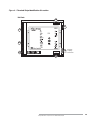
Terminal Strips Identification & Location (Figure 6.1) ................
Wiring Diagram & Connections–Main Chassis (Figure 6.2) ........
Eclipse Bi-Flame v1.8, Instruction Manual 826, 05/03
22
22
22
23
23
23
23
23
23
23
23
24
25
26
5
6
7
Sensor Installation ................................................................... 27
Introduction ...........................................................................................
Sensor Wiring ........................................................................................
Flame Rods ............................................................................................
Scanners ..................................................................................................
Scanner Sighting Considerations ......................................................
27
27
28
28
29
8
Test Procedures ...............................................................................
Introduction ...........................................................................................
Flame Signal Strength ..........................................................................
Minimum Pilot Test...............................................................................
Pilot Flame Failure Test .......................................................................
Main Flame Failure Test .......................................................................
Spark Sighting Test ................................................................................
Limits & Interlock Tests ......................................................................
30
30
30
30
31
31
31
31
9
Maintenance & Troubleshooting ..............................................
Introduction ...........................................................................................
Maintenance ...........................................................................................
Monthly Checklist ................................................................................
Yearly Checklist ....................................................................................
Troubleshooting ....................................................................................
32
32
32
32
33
34
10
Remote Display Messages ...........................................................
Introduction ...........................................................................................
Bi-Flame Operating Sequence (Table 10.1) ...................................
Remote Display Diagnostic Messages (Table 10.2) ......................
35
35
36
40
Appendix .............................................................................................
Conversion Factors .............................................................................
Illustrated Parts List .............................................................................
43
43
44
Eclipse Bi-Flame v1.8, Instruction Manual 826, 05/03
Introduction
1
PRODUCT
DESCRIPTION
The Eclipse Combustion Bi-Flame Burner Monitoring System
controls the start-up sequence and monitors the flame of two
individual gas, oil, or combination gas/oil burners connected to a
common valve train. Its dynamic on-board testing checks for
faulty relays, proof of valve closure, high and low fire switch
interlocks, and shorted air switch.
The microcomputer based system features a plug-in modular
design so any of the circuit board modules attached to the
motherboard can be replaced when power is removed. Its DIP
switches allow sequence and timing functions, as well as system
configuration. It is also capable of modulation (high and low fire
purging) and monitoring up to four auxiliary inputs, history
logging, and interfacing to valve leakage detection devices. It is UL
recognized, FM approved and CSA certified.
Figure 1.1 Bi-Flame Burner Monitoring System
Eclipse Bi-Flame v1.8, Instruction Manual 826, 05/03
7
Specifications
2
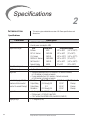
INTRODUCTION
This section gives a detailed overview of Bi-Flame specifications and
dimensions.
Specifications
Parameter
Supply
Temperature Ranges
Flame Failure Response
TFI/Pilot Interrupt
Purge Time
Contact Ratings @ 120 VAC
(maximum total connected
load not to exceed 15 amps)
Approvals
Shipping Weight
8
Description
•120 VAC (+10%, -15%), 50/60 Hz standard.
Internal power consumption: 24VA
Unit
Model Nos.
Temperature Range
Bi-Flame
6500
-40˚ to +60˚C (-40˚ to +140˚F)
90˚ U.V. Scanner
5600-90A
-20˚ to +60˚C (0˚ to 140˚F)
U.V. Scanner
5600-91
-40˚ to +125˚C (-40˚ to +257˚F)
NEMA4 UV Scanner
5600-91N4
-20˚ to +125˚C (0˚ to 257˚F)
Self-Check U.V.
5602-91
-40˚ to +60˚C (-40˚ to +140˚F)
Remote Display
6000D
0˚ to 50˚C
(32˚ to 122˚F)
• 3 seconds ±0.5 seconds.
• 5, 10 or 15 seconds selectable.
• Modulating: selectable from 0-225 seconds in 15 second increments,
or 0-15 minutes in 1 minute increments
• Process: selectable from 0-15 minutes in 1 minute increments,
or 0-60 minutes in 4 minute increments.
Function
Affected Terminals
Inductive Load Resistive Load
Output Relay
J2-4 through J2-8
1/3 HP
10 amps
Output Relay
J2-3
1/2 HP
15 amps
Modulation
J3-1 through J3-4
1/3 HP
10 amps
• UL Recognized; File MP1537 (category MCCZ2)
• FM Approved; J.I. 2Y3A5.AF (class 7610)
• CSA Certified; File 007989-0-000 (class 2632-01, 2642-01)
• 2.7 kilograms (6 lbs.)
Eclipse Bi-Flame v1.8, Instruction Manual 826, 05/03
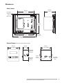
DIMENSIONS
Main Chassis
140 mm
(5-1/2")
183 mm
(7-3/16")
Mounting
Holes (4)
5 mm
(3/16") Dia.
237 mm
(9-5/16")
229 mm
(9")
21 mm
(13/16")
270 mm
(10-5/8")
Remote Display (Shown with remote keypad and reset)
102 mm
(4") Square
54 mm
(2-1/8")
89 mm
(3-1/2") Square
Mounting
Bracket &
Screw (2)
Mounting
Bracket
Slot (4)
15-pin
Port
Terminal
Eclipse Bi-Flame v1.8, Instruction Manual 826, 05/03
Contrast
Adjustment
Slot
9
Modules Description
3
INTRODUCTION
In this section, you will find descriptions of the various modules
which comprise the Bi-Flame dual burner flame monitoring system,
whether standard or optional items.
MODULE DESCRIPTION
Relay Module
AND IDENTIFICATION
The relay module contains the output relays which provide power
for operating the ignition coil, pilot valve, main valve, combustion
fan and alarm. This module is mounted in the first position on the
left of the motherboard closest to the output terminals.
Logic Module
Relay Module Location
The logic module houses the microcomputer which provides all
the sequential logic and safety start-up and shutdown circuitry. On
the front of this module is the reset, scan and enter push-buttons,
and status lights. This module is mounted in the second position
from the left of the motherboard next to the relay module.
Power Module
The power module supplies the power required for the electronic
circuitry. It is mounted in the motherboard to the right of the logic
module. The green LED on the front indicates that power is on to
the Bi-Flame.
Logic Module Location
Power Module Location
10
Eclipse Bi-Flame v1.8, Instruction Manual 826, 05/03
Sensor Module
The sensor module is the flame sensing module of the Bi-Flame. It is
mounted in the furthest right position of the mother board.
On the front of the sensor module are two “Flame On” LED’s, which
illuminate when a flame is detected at the corresponding burner.
Directly below the “Flame ON” LED are “Flame Fail” LED’s, which
energize to show the first burner to lose its signal.
Sensor Module Location
The sensor module incorporates test point connection jacks in the
front of the unit. Using these, the flame signal strength of each burner
can be measured using a 0-15 VDC, one megohm/volt meter as
explained and shown in “Flame Signal Strength” on page 30.
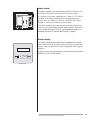
Remote Display
The remote display provides alphanumeric messages which indicate
burner status as well as annunciate lockout condition in the Bi-Flame
system. It also provides remote reset, a keypad and history logging
capability.
A cable connects the remote display to the motherboard; this cable is
available in six and 10 feet lengths.
Remote Display
Eclipse Bi-Flame v1.8, Instruction Manual 826, 05/03
11
DIP Switch Selection
INTRODUCTION
4
This section details the location, selection and description of the
Bi-Flame DIP switches, which allow for sequence and timing functions as well as system configuration.
Caution:
To avoid electric shock, shut off the power supply when installing
any control device. Flame monitoring systems must be installed
by a qualified, licensed technician.
DIP SWITCH LOCATION
All of the DIP switches are located in the logic module, which is
mounted in the second position from the left of the motherboard
next to the relay module (see page 10 for logic module location).
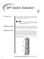
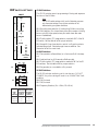
DIP SWITCH ACCESS
To gain access to the DIP switches, remove the circuit board
cover. To do this, remove the four screws which hold the cover to
the motherboard. Remove the cover by lifting up and off of the circuit boards. The logic module is the second board from the left.
Gently pull the logic module with a rocking motion to disengage
the terminal pins at the module base. The photo below shows
the DIP switch locations.
ON/OFF
S6
S4
S2
12
Eclipse Bi-Flame v1.8, Instruction Manual 826, 05/03
DIP SWITCH SETTINGS
ON/OFF
8
7
6
5
4
3
2
1
S6
50/60Hz
—
—
Number
of
PAF
S4
S2
8
7
6
5
4
3
2
1
P
U
R
G
E
X4
120/8
60/4
30/2
15/1
TFI
PILOT IMIT/IRPT
RECYCLE
DIP Switch Functions
S2
ON
—
OFF
X4
120 sec.
Time
Not 60 sec.
Added 30 sec.
15 sec.
S2 Modulation Purge Time, S4 - 8 = ON
S2
8
7
6
5
4
The S2 DIP switches permit programming of timing and sequence
functions of the Bi-Flame.
Note:
The S2 DIP switch settings at left are for illustrative purposes
only; the actual settings of any of these switches will be
determined by your system conditions.
SW1: Recycling mode selection (On=Recycling; Off=Non-recycling)
8 MOD/PROC
7
TFI
6
—
5 LEAK 110/40
4
—
3
—
2
—
1 BLOWER
8
7
6
5
4
S2 DIP Switches
ON
—
Time
Not
Added
OFF
X4
8 min.
4 min.
2 min.
1 min.
S2 Process Purge Time, S4 - 8 = OFF
SW2: Pilot selection (On= Intermittent, where pilot remains on during
burner cycle; Off =Interrupted, where pilot valve closes after main
burner is established).
SW3: Trial-for-ignition (TFI) range selection; used with SW7 of the S4
DIP switch. See the table at left for proper selection.
SW4 through 8: Purge time selection; switch in off position selects
indicated purge time. Selected purge times are additive. See
illustration at left for exact times.
S4 DIP Switches
SW1: Fan operation on flame failure (on = fan turns off; off = fan stays
on).
SW5: Leak test time (on=110 seconds; off=40 seconds).
SW7: Trial-for-ignition (TFI) range selection; used with SW3 of the S2
DIP switches. See the table at left for proper selection.
SW8: Purge mode; (on = modulation, off = process).
S6 DIP Switches
The S6 DIP switches are factory set for two burners. DO NOT
CHANGE. Any other setting will result in an “UNMATCH#” fault
condition.
SW6: Off, Not used.
SW7: Off, Not used.
SW8: Frequency Selection; (On = 50Hz, Off = 60 Hz)
AND
THEN
SW3 of S2 SW7 of S4
DIP switch DIP Switch
If the
must be
must be
TFI
turned:
needed is: turned:
Off
Off
5 seconds
On
Off
10 seconds
Off or On
On
15 seconds
Trial-for-Ignition (TFI) Settings
Eclipse Bi-Flame v1.8, Instruction Manual 826, 05/03
13
Function Summary
INTRODUCTION
5
This section describes the function features of the Bi-Flame that can
be found on the various terminal strips and the modules of the BiFlame.
Combustion Air Flow Check Terminal
The Bi-Flame checks that the combustion air flow switch is open before start-up, closed during operation and open again at burner shutdown, thus preventing operation with an air switch that is defective,
maladjusted or jumpered.
Main Fuel Valve Proof-of-Closure Terminal
The Bi-Flame checks that the main fuel valve is closed before startup and after burner shutdown. This arrangement requires a closed
position switch on the main fuel valve.
Low Fire Start Terminal
The system checks for the low fire start position prior to light-off. If
voltage is not present on this terminal within 15 minutes, the Bi-Flame
goes to lockout and alarm.
High Fire Purge Check Terminal
The system checks that the air modulation motor reached the high
fire position during high fire purge. The modulation motor or air
valve must be fitted with a high fire position switch, which is then
connected to the high fire check terminal. An air flow or pressure
switch that is set to prove sufficient purge air may be used instead
of the high fire position switch. If voltage is not present on this terminal within 15 minutes, the Bi-Flame goes to lockout and alarm.
14
Eclipse Bi-Flame v1.8, Instruction Manual 826, 05/03
Recycle Mode
When selected, the Bi-Flame will restart the sequence after flame or
air failure. The recycle mode allows the system to re-initiate the
start-up sequence automatically, once the main burners have been
operating for at least 20 seconds. If the pilot flame fails to light during recycling, the system will lock out and annunciate a pilot flame
fail. If the recycle is successful and the main burners are operational
for at least 20 seconds, the system is ready for another recycle. At
no time will the system recycle in the event of pilot flame fail.
Pilot Test Mode
This mode is entered by pressing the “Reset” and the “Enter” buttons simultaneously then releasing the “Reset” button but holding
the “Enter” button for another 10 seconds. The limits light will
flash off and on, indicating that the system is in the test mode.
In the pilot test mode, the Bi-Flame operates normally with the exception that the main valves are not energized, preventing the main burners from igniting.
To exit the pilot test mode, simply press the “Reset” button and the
Bi-Flame will exit the pilot test mode and restart the sequence. Entering the pilot test mode erases the history log.
Interrupted or Intermittent Pilot
Pilot mode is selected using the DIP switch (see “S2 DIP Switch
Settings” on page 13). An interrupted pilot shuts off after the main
flame is established. An intermittent pilot continues during the entire main flame firing cycle.
Spark, Pilot Flame and Main Flame Separation
During the trial for ignition period (TFI), the pilot and ignition outputs remain energized. At the end of the TFI, the pilot output remains on and the ignition output is de-energized. After a five second delay to prove the pilot flame, the main output is energized.
Note:
Both pilots must light within the specified TFI or a pilot flame
failure will occur. If one burner experiences either a pilot or
main flame failure, then both burners will shut down. The failed
burner will be indicated by the red “Flame Fail” light.
Eclipse Bi-Flame v1.8, Instruction Manual 826, 05/03
15
Auxiliary Inputs
This feature provides four auxiliary inputs which are monitored by
the Bi-Flame as alarm interlocks. This means that when the input
voltage is interrupted, the system locks out and will annunciate on
the optional remote display unit.
A voltage of 120 VAC must be present at the input for the Bi-Flame
system to operate. If an auxiliary input loses its voltage for more
than one second while the interlocks and limits input is powered, a
lockout condition will occur. If the Bi-Flame is equipped with a remote display unit, the following message will occur:
Aux. Input #1
AUX.LIM. #1 FAIL
LKOUT HHHH:MM:SS
Aux. Input #2
Aux. Input #3
Aux. Input #4
AUX.LIM. #2 FAIL
AUX.LIM. #3 FAIL
AUX.LIM. #4 FAIL
LKOUT HHHH:MM:SS LKOUT HHHH:MM:SS LKOUT HHHH:MM:SS
Note:
Unused auxiliary inputs should be connected to 120 VAC.
History Log
The history log is only accessible through the remote display unit
with remote reset, and when the Bi-Flame is in a “LOCKOUT” or
“LIMITS OPEN” condition. The history log records the total number of operating cycles, total recycles, cause of last recycle and the
last lockout messages up to a maximum of 10.
With a remote display available and the Bi-Flame in one of the two
conditions described above, the history log can be accessed as follows:
1) Press and hold the ENTER key on the remote display unit until
the following message appears:
TOTAL OPERATING CYCLES = XXXXXX (where X is a
digit between 1 and 9).
The record number will display as long as the ENTER key is
pressed. The scan button on the logic board also scrolls the history log.
2) If there has been a recycle, release and press the ENTER key to
see: RECYCLES TOTAL = XXXXXX then release and press
the ENTER key to see:
LAST RECYCLE BY AIR=XXXXXX or
LAST RECYCLE BY FLAME=XXXXXX
3) Release and press the ENTER key a second time. The record
number of the lockout message will be displayed:
RECORD #X (where X is the number of the most recent
lockout)
(continued on next page)
16
Eclipse Bi-Flame v1.8, Instruction Manual 826, 05/03
History Log (continued)
4) Release the ENTER key and the most recent lockout message
will display for seven seconds.
5) If you wish to see the next lockout message, press and release
the ENTER key before the seven second time duration ends of
the most recent lockout message display. This will prompt the
next lockout message. If desired, continue this procedure until
the maximum of ten lockout messages has been displayed (remember that the highest record number is the most recent
lockout message).
6) Continued pressing and releasing of the ENTER key in less than
seven seconds keeps the history log active and repeats the lockout message list; waiting longer than seven seconds deactivates
the history log mode and the next display is the last sequence
message before the history log was activated. For example, if the
message “LIMITS OPEN” was displayed when the history log was
activated, then that message will appear again after seven seconds.
7) If you wish to erase all of the lockout messages from the history log, press the RESET and ENTER keys simultaneously
while the history log is active. Release the RESET key, but hold
the ENTER key for another five seconds. Wait five seconds and
press and release the RESET key.
Modulation Contacts
The modulation feature incorporates “drive high”, “drive low”, and
“automatic” contacts into the purge sequence. This feature allows
the Bi-Flame to sequence internal dry contacts which can be used
by the customer requiring a high fire purge of the combustion
chamber before ignition.
The high fire purge time is selectable by means of S2 DIP switches
on the logic board (see “S2 DIP Switch Settings” on page 13)
With this option, the modulation terminals on J3 terminal strip will
sequence as follows:
Sequence Step
High Fire Purge
Low Fire Start
Automatic
Post Purge
Power Off
Power On/Limits Off
Alarm
Internal Contact Connections
Terminal 1 (COMMON) to Terminal 3 (HI FIRE)
Terminal 1 (COMMON) to Terminal 4 (LOW FIRE)
Terminal 1 (COMMON) to Terminal 2 (AUTO)
Terminal 1 (COMMON) to Terminal 4 (LOW FIRE)
Terminal 1 (COMMON) to Terminal 2 (AUTO)
Terminal 1 (COMMON) to Terminal 4 (LOW FIRE)
Terminal 1 (COMMON) to Terminal 4 (LOW FIRE)
The Automatic step occurs 20 seconds after the main output has
energized (see Table 10.1 beginning on page 36) and allows the
burner firing rate to be controlled by an automatic temperature
controller.
Eclipse Bi-Flame v1.8, Instruction Manual 826, 05/03
17
Valve Leak Sensing Device (VLSD) Interface
The Bi-Flame Valve Leak Sensing Device (VLSD or VDK) interface
provides a 120 VAC output which triggers the start of the test period. An input is also provided which receives a 120 VAC signal
from the VLSD. If the signal is received within the selected test period (40 or 110 seconds, see page 13), then the test has been successfully completed. This option includes the required sequential
software to initiate the valve leak test on start-up and shutdown of
the burners.
When the limits close to the Bi-Flame, the 120 VAC output to the
VLSD is activated. If an optional remote display is connected, the following message will appear:
VALVE LEAKAGE
UNDER TEST XX (where X is the remaining seconds of the
test).
If the VLSD does not activate the VLSD 120 VAC input within the
test period, an alarm lockout will occur, and the following message
will appear on the optional remote display:
VALVE LEAK FAIL
LKOUT HHHH:MM:SS
If a valve leak occurs, the fan output on the Bi-Flame will be activated to purge the combustion chamber of gases.
Note:
If the VLSD input is not used, then it should be connected to
120 VAC.
18
Eclipse Bi-Flame v1.8, Instruction Manual 826, 05/03
Remote Display Unit
The remote display with keypad allows remote reset and activation
of the history log option. It is panel mountable and features a backlit liquid crystal display in a 1/4 DIN housing. It connects to the BiFlame by a six or ten foot cable. The display incorporates the following features:
1) Provides status messages for the Bi-Flame sequence. (See Section 10)
2) Indicates lockout conditions when they occur, as well as the
amount of time into the sequence when the lockout occurred
and the amount of time elapsed from lockout.
3) Provides continuous monitoring of each burner’s flame signal
strength during main burner operation. (Pressing ENTER once
will lock on a particular burner’s status; pressing ENTER a second time will resume scrolling).
4) Incorporates a remote reset key.
5) Provides the interface required for the History Log.
6) Incorporates keys for pilot test mode.
RS232 Communication Interfaces (RS485 optional)
Terminals 1, 5, and 6 on Bi-Flame terminal strip J7 provide a serial
ASCII output communication interface for remotely monitoring the
system sequence and status using a terminal or a modem; refer to
Section 10 for the types of messages sent by the Bi-Flame.
The communications protocol is 8 bit, no parity, 1 stop bit and1200
baud.This feature is provided standard as a RS232 interface.The RS485
interface is optional.
Sending a carriage return (<CR> = ASCII Hex 0D) from the terminal
causes the Bi-Flame to retransmit the last message. Sending a CTRLE (<ENQ> = ASCII Hex 05) accesses the optional history log.
LOGIC MODULE STATUS
LIGHTS & PUSH-BUTTONS
The logic module provides all the sequential logic, and safety startup and shutdown circuitry. On the front of the module is the reset,
scan and enter push-buttons, and status lights. This section describes the their respective functions.
Limits
This LED illuminates when the operation limits are made. These limits
are wired in series to terminal J1-1.This input becomes energized to
begin the burner sequence.When in the test mode, this LED flashes
(see “Pilot Test Mode” on page 15).
Eclipse Bi-Flame v1.8, Instruction Manual 826, 05/03
19
Air
This LED illuminates when the air switch is closed and power is
thereby applied to the air switch input. The Bi-Flame also checks this
input for an air switch short (see “Combustion Air Flow Check Terminal” on page 14).
Purge
This LED illuminates whenever the combustion blower is energized,
including the purge period and the main burner period of the sequence. It blinks on and off while the purge is in process and remains
constant when the purge process is complete.
Burner On
This LED illuminates when the main gas valve is energized, permitting
gas flow to all the burners.
Fault
This LED illuminates when a system fault is detected (see “System
Faults” on page 21).
Alarm
This LED illuminates when an alarm condition causes a system lockout (see “System Lockout Conditions” on page 21).
Low Fire
This LED illuminates during the low fire period of the purge cycle.
High Fire
This LED illuminates during the high fire period of the purge cycle.
Scan
This push-button can be used to scroll the history log.
Enter
This push-button is used with the RESET button to enable the pilot
test mode.
Reset
This push-button resets the control. It is also used with the ENTER
button to enable the pilot test mode.
20
Eclipse Bi-Flame v1.8, Instruction Manual 826, 05/03
System Faults
A system fault (illuminated by the fault LED on the logic cards) prevents gas ignition but does not lock out the system. System fault conditions are as follows:
1) If a flame is detected out of sequence, which may be caused by:
a) a faulty scanner
b) electrical interference on the sensor leads
c) a flame exists in the burner due to a gas leak or other condition.
2) Air flow switch closed before start-up.
System Lockout Conditions
A system lockout will occur (illuminated by the alarm LED on the
logic card) for any of the following conditions:
1) Air failure–loss of combustion anytime during the operational
cycle.
2) Pilot flame fail–loss of flame during the trial for pilot ignition
period.
3) Main flame fail–loss of flame during the main burner trial for ignition.
4) Main fuel valve–open after cycle shutdown or before start-up
with interlocks closed.
5) Unmatched burners–the S6 DIP switch is not set correctly (see
“S6 DIP Switch Settings” on page 13).
6) Relay fail–failure of Bi-Flame internal relays.
7) Low fire fail–low fire switch open for more than 15 minutes
prior to trial for ignition.
8) High fire fail–high fire switch has not closed within 15 minutes
of high fire purge.
9) Flame fail–loss of flame after main flame has been established.
10) Auxiliary input fail–loss of input voltage to any of the four
“Aux” terminals after the limit input is made.
11) Valve leak fail–valve leak sensing device has detected a leak.
12) Wiring error which puts external voltage on any of the output
terminals.
13) Welded internal contacts or other malfunctions in the Bi-Flame.
Eclipse Bi-Flame v1.8, Instruction Manual 826, 05/03
21
System Installation
INTRODUCTION
6
In this section, the necessary procedures are detailed to integrate a
Bi-Flame into a burner system; Figure 6.1 (page 25) illustrates the
various terminal strips mentioned.
Note:
Shut off the power supply before any module is removed or
replaced from the unit, including the remote display.
Caution:
Installation and maintenance must conform with the National
Electrical Code and all other national and local codes and authorities having jurisdiction.
INTERLOCKS AND
LIMIT SWITCH INPUT
COMBUSTION AIR
SWITCH INPUT
Interlocks are generally pressure or temperature switches which,
when activated, start the burner. Limit switches are generally
pressure, temperature and other switches which, when activated,
stop the burner. The interlocks and limit switches are wired in
series. A break in this circuit will shut the burner down, but will not
produce an alarm. This input is considered the normal operation
control input to the Bi-Flame system.
This input is for monitoring the combustion air switch separately
from other interlocks and limits. When wired to this input, the air
switch will be proven open before start-up and after shutdown. It
will also be proven closed 10 seconds after the combustion air
blower is energized.
If the air switch opens during the main firing cycle, the system will
either lockout or recycle, depending on the DIP switch selection.
If this terminal is not used, place a jumper between the combustion
blower output (terminal 3 on terminal strip J2) and the air switch
input (terminal 2 on terminal strip J1). This jumper must not be
used in place of a required air flow switch interlock.
If the combustion air blower is controlled outside of the Bi-Flame
system, then the air switch must be wired between the combustion
blower output and the air switch input. Connecting the air switch
in this manner will prevent the open contact (air short) check on
the switch.
22
Eclipse Bi-Flame v1.8, Instruction Manual 826, 05/03
IGNITION WIRING
Route ignition wiring a sufficient distance from all sensors and other
low voltage wiring to avoid electrical interference, which may cause
erratic operation of the Bi-Flame system.
Caution:
Do not connect multiple ignition coils in excess of output relay
contact rating
COMMUNICATION
WIRING
Route communication wiring, using shielded cable, a sufficient
distance from ignition and other high voltage wiring to avoid
electrical interference.
POWER SUPPLY
All input power must be single phase 120 VAC, 60/50 Hz selectable,
see page 13. All circuits must have a common 15 amp fuse and
disconnect. The neutral must be grounded. Do not use solid-state
triac output devices in any of the input circuits. 120 VAC wiring
must be at least 90°C 16 AWG minimum and satisfy all applicable
codes.
LOW FIRE POSITION
It is possible to wire the system for checking low fire start position
prior to pilot ignition. To use this feature, the low fire start switch
must be connected to the low fire start input (terminal 4 on
terminal strip J1). If this feature is not used, a jumper must be
placed between terminals 1 and 4 on terminal strip J1.
INPUT
MAIN VALVE
PROOF-OF-CLOSURE
The system can be wired to check for the proof of valve closure
(POVC) switch on the main gas valve prior to start-up and after
the end of the burner cycle.
To use this feature the POVC switch must be connected to the
POVC switch input (terminal 3 on terminal strip J1). If this feature
is not used, a jumper must be placed between terminals 2 on
terminal strip J2 and 3 on terminal strip J1.
HIGH FIRE POSITION
INPUT
AUXILIARY INPUTS
The system can be wired to check for high fire position during the
high fire purge portion of the sequence. To use this feature, the
high fire position switch must be connected to the high fire input
(terminal 5 on terminal strip J1). If this feature is not used, a jumper
must be placed between terminals 1 and 5 on terminal strip J1.
The system can be wired to check auxiliary status conditions with
the four auxiliary inputs. To use this feature, the auxiliary input
switches must be wired to the auxiliary inputs (terminals 7,8,9 and
10 on terminal strip J1). If this feature is not used, these inputs
must be connected to 120 VAC.
Eclipse Bi-Flame v1.8, Instruction Manual 826, 05/03
23
REMOTE RESET
This feature permits remote mounting of a switch to reset the BiFlame. To use this feature, a normally closed remote reset switch
must be wired between terminals 1 and 4 on terminal strip J7. When
it is depressed or actuated, the connection between the terminals is
momentarily interrupted and resets the Bi-Flame. This is a low
voltage signal circuit that must be routed separately from other
control voltage wiring. Use two-conductor shielded cable with the
shield connected on one end only to terminal 1 of J7.
Note:
If reset is required from both the dispaly and the J7 terminals, use
a normally open switch.
REMOTE DISPLAY
When installed, the remote display must be grounded. Panel
mounting is through a 1/4 DIN cutout (see page 9). Use either the
six or ten foot cable to connect it to the motherboard.
Warning:
Power must be off when inserting or removing
the cable.
24
Eclipse Bi-Flame v1.8, Instruction Manual 826, 05/03
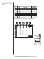
Figure 6.1 Terminal Strips Identification & Location
Main Chassis
J4
J7
J1
J2
J6
J3
Remote
Display
Connection
J5
Eclipse Bi-Flame v1.8, Instruction Manual 826, 05/03
25
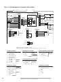
Figure 6.2 Wiring Diagram & Connections–Main Chassis
On/Off
15 A. Fuse
120 VAC
J1
Terminals
Interlocks & Limits
Air Flow
1
High Fire
Aux. Input #21
Aux. Input #31
Aux. Input #41
3
7
4
3
4
P1-4
5
+
6
Pilot
Pilot Gas Valve
Ignition
Leak Detect
7
VDK/VLSD
Alarm
9
Ignition Coil
10
J7
Terminals
Yellow
Shield
Low Fire
-
8
Flame Rod
Blue
High Fire
P1-2
Block Valve
Main
4
8
J4
Terminals2
2
P1-1
Main Gas Valve
Fan Motor
3
Temperature
Controller
4 to 20 mA
Auto
2
6
ACT004
Common
1
5
Aux. Input #11
MS
2
J3
Terminals
4
Leak Detect
Neutral
1
3
Low Fire
1
J2
Terminals
Customer Supplied (if used)
2
POVC
VDK/VLSD
Neutral
Burner #1
5600-90A
or 5600-91
U.V. Scanner
6
Rx
5
Tx
Ignition Coil
J5
Terminals2
RS 232
4
2
3
3
2
4
1
Blue
1
Yellow
Flame Rod
5600-90A
or 5600-91
U.V. Scanner
Burner #2
Shield
Remote
Reset
Pushbutton
(if required)
B
120 VAC
Neutral
A
Signal (UV)
GND (Return)
C
D
5602-91
U.V.
Self-Check
Scanner
1 When not used, must be tied into 120 VAC.
2 Using both sensors isn’t mandatory; you may use a flame rod, or a UV scanner, or both.
J1 (Input) Terminals
1
2
3
4
5
6
7
8
9
10
–
–
–
–
–
–
–
–
–
–
J3 (Modulation) Terminals
Limits Input
Air Switch Input
POVC Switch Input
Low Fire Switch Input
High Fire Switch Input
VDK/VLDS Input
Aux. #11
Auxiliary
Aux. #21
Inputs
Aux. #31
1
Aux. #4
1
2
3
4
–
–
–
–
Common
Auto
Hi Fire
Low Fire
Modulation
Motor
Connections
for High Fire &
Low Fire Start
26
–
–
–
–
–
–
–
–
Neutral
120 VAC
Fan
Main Gas Valve
Pilot Gas Valve
Ignition Transformer
VDK/VLSD
Alarm
1
2
3
4
–
–
–
–
U.V. (Blue)
Ground (Yellow)
Flame Rod
Shield Connection
Burner #2
J4 (Sensors/Burners 1 & 3) Terminals2
1
2
3
4
–
–
–
–
Flame Rod
Ground (Yellow)
U.V. (Blue)
Shield Connection
Burner #1
J7 (Interface) Terminals
J2 (Output) Terminals
1
2
3
4
5
6
7
8
J5 (Sensors/Burners 2 & 4) Terminals2
Bi-Flame
Power Inputs
Outputs
Eclipse Bi-Flame v1.8, Instruction Manual 826, 05/03
6
5
4
3
2
1
–
–
–
–
–
–
RS 232/RS 485 Interface
RS 232/RS 485 Interface
Reset
Scan
Enter
Ground
Sensor Installation
INTRODUCTION
7
This section describes the proper wiring, installation and sighting considerations for all sensors that can be used with a Bi-Flame.
Warning
Incorrect sensor installation may cause the sensor
to generate a false flame signal, causing unburned
fuel to collect in the combustion chamber. The result can be explosions, injuries and property damage. Be certain that the flame sensor detects only
pilot and main flames, not glowing refractory,
burner or ignition parts.
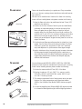
SENSOR WIRING
Route sensor wiring a sufficient distance from ignition and other
high voltage or high current wiring to avoid electrical interference.
Interference from ground currents, nearby conductors, radio-frequency emitters (wireless divices), and inverter drives can induce false
flame signals. Shielded cables can help reduce interference with the
shield connected to ground at the control end only. The wire type
and its capacitance (picofarads or microfarads) to ground may cause
low signal problems, so a grounded shield may decrease the signal due
to the cable’s internal capacitance. Multiple U.V. tube-type sensor
leads run together without shielding may interfere or “cross talk”, so
the shield or flexible armor must be grounded to prevent this situation. For flame rod sensor runs approximately 100 feet (30 meters)
or greater, use Eclipse part number 21741 coax cable. To achieve the
maximum wiring distance, the shield should not be grounded (keep
in mind that an ungrounded shield provides less protection against
electrical interference).
Do not ground the shield to terminal GND.
Note:
Unshielded sensor wiring must not be run in common with other
wires; it must be run in separate conduit. Multiple unshielded
flame sensor wiring must not be run together in a common
conduit or wireway. Use #14 to #18 AWG wire suitable for 90°C
(194°F) and 600 volt insulation, or better grade if required by
the application. Multiple shielded cables can be run in a common
conduit.
Eclipse Bi-Flame v1.8, Instruction Manual 826, 05/03
27
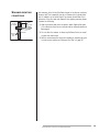
FLAME RODS
Flame rods should be used only on gas burners. They accumulate
soot on oil burners, causing nuisance shutdowns and unsafe operating conditions.
See the burner manufacturer’s literature for flame rod mounting
location. When installing flame rods, please consider the following:
1) Keep the flame rod as short as possible and at least 13 mm (1/2")
away from any refractory.
Flame Rod
WRONG
Rod Detects
Weak Pilot
2) Position the rod into the side of both the pilot and main flames,
preferably at a descending angle to minimize drooping of the
flame rod against burner parts. Flame rod position must adequately detect the pilot flame at all burner draft conditions. Extend the rod 13 mm (1/2") into nonluminous flames, such as blue
flames from burning an air/gas mixture. For partially luminous
flames, such as atmospheric air/gas mixtures, place the rod at the
edge of the flame.
CORRECT
Rod Detects
Only Strong
Pilot Flame
PILOT
3) Provide a burner/flame grounding area that is at least four times
greater than the flame rod area contacting the flame. The flame
rod/burner ground ratio and position of the rod in the flame
may need adjustment to yield maximum flame signal strength.
Flame Rod Position
4) Ignition interference from the spark plug may increase or decrease
the flame signal strength. Reversing the ignition transformer primary leads may reverse this effect. Reducing the spark gap or adding grounding area between the flame rod and spark plug may
eliminate the interference.
SCANNERS
Use only Eclipse model 5600-90A, 5600-91, 5602-91or 5600-91N4
scanners. Consult the burner manufacturer’s instructions for mounting
location. When installing scanners, please consider the following:
1) Position the scanner within 457 mm (18") of the flame.
U.V. Scanner
(Model 5600-91)
2) Bushing threads are 1/2 inch F.N.P.T. for scanner models
5600-90A, 5600-91 and 5600-91N4; model 5602-91 has 1
inch F.N.P.T. bushing threads.
90° U.V.
Scanner
(Model 5600-90A)
3) The ambient temperature limits of each scanner varies, (see specifications). For higher temperatures, use Eclipse heat insulator
49099 or the Heat Block Seal, Model 23HBS, that has a purge fitting.
4) An optional magnifying lens (Eclipse #49600-98) may also be used
to increase the flame signal strength in difficult sighting situations.
Self-Check
U.V. Scanner
(Model 5602-91)
28
Eclipse Bi-Flame v1.8, Instruction Manual 826, 05/03
SCANNER SIGHTING
CONDITIONS
MAIN
BURNER
Scanner
Sight
Line
1/3 of
Flame Length
SCANNER
U.V. Scanner Sighting
Aim scanners at the third of the flame closest to the burner nozzle, as
shown at left. This is especially true for oil flames which typically have
less UV radiation in the outer flame.The scanner should view the intersection of the pilot and main flames.When sighting scanners, please
consider the following:
1) Sight the scanner away from the ignition spark. Sighting the spark
or its reflections from burner internals can be misinterpreted as a
flame signal.
2) Do not allow the scanner to detect a pilot flame that is too small
to ignite the main burner.
3) Perform a minimum pilot test when installing or adjusting any pilot
or main burner system; see “Minimum Pilot Test” on page 30.
Eclipse Bi-Flame v1.8, Instruction Manual 826, 05/03
29
Test Procedures
8
INTRODUCTION
This section describes the test procedures that must be performed
after installation to insure that the Bi-Flame is operating properly;
these procedures are mandatory.
FLAME SIGNAL
Insert the positive probe of a 0-15 VDC, one megohm/volt meter into
the test point on the front cover, as shown in the photo at left. Connect the negative probe to ground. A good flame signal strength will
read between 6 and 11 VDC; anything below 4 VDC is inadequate.
STRENGTH
MINIMUM PILOT TEST
Run the following test procedures to ensure that the sensor will
not detect a pilot flame too small to reliably light the main flame:
1) Manually shut off the fuel supply to the burner, but not to the pilot.
2) Start the system normally.
3) To enter the pilot test mode, press the RESET and ENTER buttons simultaneously. Then release the RESET button but keep
the ENTER button depressed for another 10 seconds. The Limits
LED will blink, signalling that the system is in the pilot test mode.
4) The control will hold the operating sequence at the pilot flame
step. Measure signal strength as described above.
Voltmeter hook-up to the Bi-Flame
5) Reduce pilot fuel until the flame relay drops out. Increase pilot
fuel until the flame signal is greater than 4 VDC, and flame relay
just manages to pull in. This is the minimum pilot. If you don’t
think this flame will be able to safely light the main burner, realign the sensor so that it requires a larger pilot flame and repeat steps 2 through 5.
6) Push the RESET button to exit the test mode and begin the
normal start-up sequence again.
7) When the sequence reaches the main flame trial for ignition,
smoothly restore the fuel supply to the burner. If the main
burner does not light within five seconds, immediately shut off
the burner supply to shut down the system. Realign the sensor
so that it requires a larger pilot flame. Repeat steps 1 through
6 until the main burner lights off smoothly and reliably.
30
Eclipse Bi-Flame v1.8, Instruction Manual 826, 05/03
PILOT FLAME FAILURE
TEST
1) Manually shut off the fuel supply to one individual pilot and
main burner, or all burners if the system has a single fuel supply.
2) Place system in pilot test mode (please refer to page 15).
3) Start the system normally. The controller should lock out*; if it
doesn’t, then the controller is detecting a false flame signal (see
Section 7). Find the problem and correct it before resuming
normal operation.
4) Repeat steps 1 through 4 until all burners have been tested.
MAIN FLAME FAIULRE
TEST (For Interrupted Pilot Systems)
1) Manually shut off the fuel supply to the main burner, or all burners if the system has a single fuel supply, but not to the pilot.
2) Start the system normally. This should ignite the pilot and lock
out* after pilot interruption. If the system does not lock out, the
controller is detecting a false flame signal (see Section 7). Find
the problem and correct it before resuming normal operation.
3) Repeat steps 1 through 3 until all burners have been tested.
SPARK SIGHTING TEST
1) Manually shut off the fuel supply to the pilot and main burner.
2) Start the system normally.
3) Measure the flame signal as described in “Flame Signal Strength”
in this section.
4) If a flame signal greater than 4 VDC is measured for more than
three seconds during the trial for ignition, the sensor is picking
up a signal from the spark plug or the ignition current is interfering with the sensor wiring. If this is an abnormal condition,
correct before resuming normal operation.
LIMITS AND INTERLOCK
TESTS
Periodically check all interlock and limit switches by manually tripping them during burner operation to make sure they cause the
system to shut down.
Warning
Never operate a system that is improperly adjusted or
has faulty interlocks or limit switches. Always replace
faulty equipment with new equipment before resuming operation. Operating a system with defective
safety equipment can cause explosions, injuries, and
property damage.
* The burner at which a flame fails will be identified by the red “Flame Failure” LED on the cover.
Eclipse Bi-Flame v1.8, Instruction Manual 826, 05/03
31
Maintenance and
Troubleshooting
INTRODUCTION
9
This section is divided into two parts:
• The first part describes the maintenance procedures.
• The second part helps you to identify problems that may occur,
and gives advice on how to solve these problems.
MAINTENANCE
Preventative maintenance is the key to a reliable, safe and efficient
system. The core of any preventive maintenance program is a list of
periodic tasks.
In the paragraphs that follow are suggestions for a monthly list and
a yearly list.
Note:
The monthly list and the yearly list are an average interval. If
your environment is dirty, then the intervals may be shorter.
Caution:
Turn off power before disconnecting or installing sensors, controls or modules.
Monthly Checklist
1. Inspect flame-sensing devices for good condition and cleanliness.
Keep the glass lens of scanners clean with a soft, damp cloth,
since small amounts of dust will measurably reduce the flame
signal strength. Wash the flame rod electrode and insulator with
soap and water, then rinse and dry thoroughly.
2. Test all the alarm systems for proper signals.
3. Check ignition spark electrodes and check proper gap.
4. Test interlock sequence of all safety equipment as described in
Test Procedures: manually make each interlock fail, noting what
related equipment closes or stops as specified by the manufacturer.
Test flame safeguard by manually shutting off gas to the burner.
32
Eclipse Bi-Flame v1.8, Instruction Manual 826, 05/03
Yearly Checklist
1. Test (leak test) safety shut-off valves for tightness of closure.
2. Test pressure switch settings by checking switch movements against pressure
setting and comparing with actual impulse pressure.
3. Visually check ignition cable and connectors.
4. Make sure that the following components are not damaged or distorted:
• the burner nozzle
• the spark plugs
• the flame sensors
• the flame tube or combustion block of the burner
Eclipse Bi-Flame v1.8, Instruction Manual 826, 05/03
33
TROUBLESHOOTING
PROBLEM
POSSIBLE CAUSE
Cannot initiate start sequence
SOLUTION
• Main valve is not closed.
Check proof-of-valve-closure switch.
• Air pressure switch has not made
contact.
Check air pressure switch adjustment.
Check air filter.
Check blower rotation.
Check outlet pressure from blower.
• High gas pressure switch has tripped.
Check incoming gas pressure; adjust
gas pressure if necessary.
Check pressure switch setting and
operation.
• Low gas pressure switch has tripped.
Check incoming gas pressure; adjust
gas pressure if necessary.
Check pressure switch setting and
operation.
34
• Malfunction of flame safeguard system
such as a shorted-out flame sensor
or electrical noise in the sensor line.
Have qualified electrician investigate
and rectify.
• Purge cycle not completed.
Check flame safeguard system, or
purge timer.
• Main power is off.
Make sure power is on to control
system.
• No power to control unit.
Call qualified electrician to
investigate.
Scrambled messages on remote
display.
• Improper grounding in system.
Check grounding in system.
“UNSAFE AIR SHORT” message
appears on display.
• Improperly adjusted air switch.
Check air switch settings.
• Air switch either shorted or wired
wrong.
Check wiring to air switch.
Burner flame fails but no flame
failure indication occurs.
• A faulty scanner.
Check scanner as explained in
checklists in “Maintenance” portion
of this Section.
• Improperly connected sensor wires.
Check wiring diagram on page 26
as well as appropriate sensor
information in Section 7.
• Electrical interference from other
current carrying wires.
Check Note information on page
27 regarding sensor wiring.
Eclipse Bi-Flame v1.8, Instruction Manual 826, 05/03
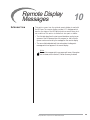
Remote Display
Messages
INTRODUCTION
10
This section covers how the optional remote display is used with
the Bi-Flame. The remote display provides LCD messages which
monitor the status of the Bi-Flame’s functions as well as any lockout conditions. This section is divided into two parts or tables:
• The first table describes the start-up and shutdown monitoring sequences of the Bi-Flame and how the progress (or halt) of the sequence can be monitored by the messages on the remote display.
• The second table alphabetically lists and explains the diagnostic
messages which can appear on the remote display.
Note:
Some of the messages which may appear with some of the options
are not shown; refer to Section 5, Function Summary, for details.
Eclipse Bi-Flame v1.8, Instruction Manual 826, 05/03
35
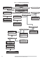
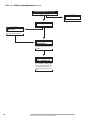
Table 10.1 Bi-Flame Operating Sequence
POWER ON
Was internal safe start check successful?
NORMAL MESSAGE
YES
VERSION VX.X
CHECKSUM = XXXX
NO
Various lockout messages
EXTERNAL INTERLOCK CHECKS
Is flame signal present?
ERROR MESSAGE #1
YES
UNSAFE FLAME ON
If signal is eliminated within 30
seconds, sequence continues. If
not, then . . .
NO
ERROR MESSAGE #2 – 30 SECONDS AFTER #1
YES
Is voltage present at air flow switch?
ERROR MESSAGE #1
YES
UNSAFE AIR SHORT
UNSAFE FLAME ON
LKOUT XXXX:XX:XX
Is proof of closure circuit closed?
NO
NO
ERROR MESSAGE
MAIN VALVE FAIL
LKOUT XXXX:XX:XX
If switch is not opened within
30 seconds and the limit input is
present....
Fan and Alarm energized.
Fan and Alarm energized.
ERROR MESSAGE #2 – 30 SECONDS AFTER #1
UNSAFE AIR SHORT
LKOUT XXXX:XX:XX
Fan and Alarm energized.
Is voltage present at interlock switch?
Is voltage present at AUX inputs ?
YES
NO
ERROR MESSAGE
NORMAL MESSAGE
YES
VALVE LEAKAGE
UNDER TEST XX
Countdown of XX based on DIP
switch
NO
ERROR MESSAGE
AUX. LIM. # X FAIL
LKOUT XXXX:XX:XX
#X is 1, 2, 3, or 4 to show
absent input
Is voltage present at VDK input
before time out?
YES
NO
ERROR MESSAGE
VALVE LEAK FAIL
LKOUT XXXX:XX:XX
NORMAL MESSAGE
Fan and alarm energized.
SAFE START OK
VX.X CS=XXXX
NORMAL MESSAGE
FAN ENERGIZED
Fan output is energized; modulator is sent to low fire.
BURNER START-UP
(see next page)
36
Eclipse Bi-Flame v1.8, Instruction Manual 826, 05/03
LIMITS OPEN
TIME = XXXX:XX:XX
Holds until answer is yes.
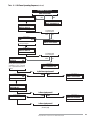
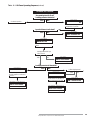
Table 10.1 Bi-Flame Operating Sequence (continued)
BURNER START-UP
Is voltage present at air flow switch
within ten seconds?
NORMAL MESSAGE
AIR PROVEN
YES
NO
ERROR MESSAGE
AIR NOT PROVEN
LKOUT XXXX:XX:XX
NORMAL MESSAGE
WAIT FOR HI. FIRE
SWITCH XX:XX
Modulator sent to high fire.
Is voltage present
at high fire input?
YES
NO
NORMAL MESSAGE
PURGE AT HIGH
FIRE
XX
Countdown of “XX” seconds
as set by DIP switch.
ERROR MESSAGE
HIGH FIRE FAIL
LKOUT XXXX:XX:XX
NORMAL MESSAGE
WAIT FOR LO.FIRE
SWITCH XX:XX
Modulator sent to low fire.
Is voltage present
at low fire input?
NORMAL MESSAGE
PILOT TRIAL FOR
IGNITION
XX
Spark energized until pilot flame
proven; pilot valve energized for
countdown of “XX” seconds
(“XX” equals selected trial for
ignition).
YES
NO
ERROR MESSAGE
LOW FIRE FAIL
LKOUT XXXX:XX:XX
Is pilot flame signal present?
NORMAL MESSAGE
PILOT ON
YES
NO
XX
After “XX” equals zero (0)...
ERROR MESSAGE
PILOT # (0X) FAILED
LKOUT XXXX:XX:XX
X = burner number.
NORMAL MESSAGE
PILOT ON
IGNITION OFF
Delay 5 seconds.
Is flame signal present?
NORMAL MESSAGE
MAIN FLAME ON
YES
NO
ERROR MESSAGE
MAIN # (0X) FAILED
LKOUT XXXX:XX:XX
X = burner number.
Is flame signal present?
(see next page)
Eclipse Bi-Flame v1.8, Instruction Manual 826, 05/03
37
Table 10.1 Bi-Flame Operating Sequence (continued)
BURNER START-UP (continued)
Is flame signal present ?
YES
NO
ERROR MESSAGE
MAIN # (OX) FAILED
X = burner number.
NORMAL MESSAGE
MAIN FLAME ON
NORMAL MESSAGE
MAIN FLAME ON
PILOT OFF
IF Interrupted Pilot is selected
Pilot will shut off 10 seconds
after main flame is energized.
NORMAL MESSAGE
AUTOMATIC
MODULATION
Modulator sent to automatic 20
seconds after main valve is
energized.
NORMAL MESSAGE
FLAME #(OX) XX.XV
TIME = XXXX:XX:XX
Flame signal = XX.X Volts DC;
(X) = Number of burner being
monitored; the Bi-Flame will
scroll through each burner continuously during the burner-on
cycle.
38
Eclipse Bi-Flame v1.8, Instruction Manual 826, 05/03
Table 10.1 Bi-Flame Operating Sequence (continued)
BURNER SHUTDOWN
Shutdown is started by opening
the operating interlock circuit.
Is voltage present at interlocks?
YES
Continued operation.
NORMAL MESSAGE
NO
POST PURGE
XX
Fuel valves de-energized; fan
energized for 15 seconds.
Is proof of closure circuit closed?
YES
ERROR MESSAGE
NO
MAIN VALVE FAIL
LKOUT XXXX:XX:XX
Fan and alarm energized.
NORMAL MESSAGE
VALVE LEAKAGE
UNDER TEST XX
Countdown of XX based on DIP
switch
Is voltage present at VDK input
before time out?
YES
ERROR MESSAGE
NO
VALVE LEAK FAIL
LKOUT XXXX:XX:XX
Fan and alarm energized.
Is voltage present at air flow switch?
ERROR MESSAGE #1
UNSAFE AIR SHORT
If switch is opened within 30
seconds, sequence continues. If
not, then . . .
YES
NO
Is flame signal present?
ERROR MESSAGE #1
UNSAFE FLAME ON
Fan is energized. If signal is eliminated within 30 seconds, sequence continues. If not, then . .
ERROR MESSAGE #2 – 30 SECONDS AFTER #1
YES
NO
NORMAL MESSAGE
LIMITS OPEN
TIME = XXXX:XX:XX
UNSAFE AIR SHORT
LKOUT XXXX:XX:XX
Alarm energized.
ERROR MESSAGE #2 – 30 SECONDS AFTER #1
UNSAFE FLAME ON
LKOUT XXXX:XX:XX
Fan and Alarm energized.
Eclipse Bi-Flame v1.8, Instruction Manual 826, 05/03
39
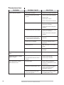
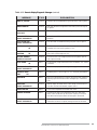
Table 10.2 Remote Display Diagnostic Messages (Listed Alphabetically)
MESSAGE
40
TYPE
EXPLANATION
AIR FAILURE
LKOUT XXXX:XX:XX
Lockout
Combustion air flow limit switch (strip J1, terminal 2) opened for
more than two seconds once initially proven.
AIR FAILURE
RECYCLING
Status
Combustion air flow limit switch (strip J1, terminal 2) opened;
control will recycle once if “recycle” DIP switch has been selected.
AIR NOT PROVEN
LKOUT XXXX:XX:XX
Lockout
Combustion air flow limit switch (strip J1, terminal 2) did not
make within ten seconds of fan being energized.
AIR PROVEN
Status
Combustion air flow limit switch (strip J1, terminal 2) closed
within ten seconds of fan being energized.
AUTOMATIC
MODULATION
Status
Modulating motor is sent to automatic operation. Terminal 1 is
connected to terminal 2 on terminal strip J3.
AUX.LIM.#1 FAIL
LKOUT XXXX:XX:XX
Lockout
Auxiliary input #1 has lost its voltage during system operation,
causing a lockout at the indicated time.
AUX.LIM.#2 FAIL
LKOUT XXXX:XX:XX
Lockout
Auxiliary input #2 has lost its voltage during system operation,
causing a lockout at the indicated time.
AUX.LIM.#3 FAIL
LKOUT XXXX:XX:XX
Lockout
Auxiliary input #3 has lost its voltage during system operation,
causing a lockout at the indicated time.
AUX.LIM.# 4 FAIL
LKOUT XXXX:XX:XX
Lockout
Auxiliary input #4 has lost its voltage during system operation,
causing a lockout at the indicated time.
FAN ENERGIZED
Status
Blower motor (strip J2, terminal 3) is energized at the start of pre-purge.
FLAME # ( ) FAIL
RECYCLING
Status
Main flame lost during automatic modulation; control will recycle
once if “recycle” has been selected.
FLAME # (X) FAILED
LKOUT XXXX:XX:XX
Lockout
Main flame lost during operation in the automatic modulation
mode. Burner number (X) given of failed unit.
FLAME # (Y) XX.XV
TIME=XXXX:XX:XX
Status
Main flame of burner number (Y) is proven in the automatic modulation mode; flame strength is XX.XV (volts DC). Elapsed time is
shown in hours:minutes:seconds.
HI FIRE FAIL
Lockout
High damper or high purge rate switch did not make and hold for
high pre-purgee.
INTERNAL FAULT
Lockout
Internal control failure; replace controller.
LIMITS OPEN
TIME=XXXX:XX:XX
Status
The controller has completed its internal checks and is standing by
for the interlocks (strip J1, terminal 1) to close.
LOW FIRE FAIL
LKOUT XXXX:XX:XX
Lockout
Low fire switch (strip J1, terminal 4) is open just prior to pilot trial
for ignition.
Eclipse Bi-Flame v1.8, Instruction Manual 826, 05/03
Table 10.2 Remote Display Diagnostic Messages (continued)
MESSAGE
TYPE
EXPLANATION
MAIN # ( ) FAILED
Lockout
Main flame was not established during the main burner trial for ignition.
MAIN FLAME ON
Lockout
Main valve has been energized and main flame proven during trial
for ignition.
MAIN FLAME ON
PILOT OFF
Status
Pilot valve (strip J2, terminal 5) is de-energized and main flame is on.
MAIN VALVE FAIL
LKOUT XXXX:XX:XX
Lockout
Main valve proof-of-closure is open before startup or after burner
shutdown.
PILOT FLAME FAIL
LKOUT XXXX:XX:XX
Lockout
Pilot flame was not established during the pilot trial for ignition.
PILOT ON
Status
Pilot flame is proven; transformer is de-energized; remaining
countdown for pilot trial for ignition is “XX”.
PILOT TRIAL FOR
IGNITION
XX
Status
Pilot valve and ignition transformer are energized; countdown for
pilot trial for ignition begins at “XX”.
PLT/MVL ENERGIZ.
XX:XX:XX LOCKOUT
Lockout
An external source of voltage is present on the ignition, pilot or
main output terminals.
POST PURGE
Status
15 second post purge is started on burner shutdown; “XX” shows
countdown.
PROGM SWITCH ERR
LKOUT XXXX:XX:XX
Lockout
DIP switch improperly set or changed during cycle.
PURGE AT HIGH
FIRE
XX
Status
Modulating motor is sent to high fire; “XX” shows purge countdown.
RECORD #X
Status
Part of the optional history log which records the total number of
operating cycles and the last lockout messages up to a maximum
of 10.
RELAY FAIL
LKOUT XXXX:XX:XX
Lockout
Internal relay(s) fail initial check. Check ratings. If lockout still occurs after overload is eliminated, replace control.
SAFE START OK
Status
Control has completed internal safe-start check.
UNSAFE AIR SHORT
Status
Combustion air switch is closed before start-up or after shutdown; control holds start-up until switch re-opens; if interlocks
close before switch opens, alarm will energize in 30 seconds.
UNSAFE AIR SHORT
LKOUT XXXX:XX:XX
Lockout
Same conditions as above, except the interlocks closed for 30 seconds before the switch re-opened, causing a lockout and the alarm.
XX
XX
Eclipse Bi-Flame v1.8, Instruction Manual 826, 05/03
41
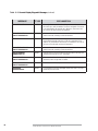
Table 10.2 Remote Display Diagnostic Messages (continued)
MESSAGE
42
TYPE
EXPLANATION
UNSAFE FLAME ON
Hold
Flame signal—actual, induced, or faulty scanner—is detected before start-up or after shutdown. The fan is energized. If the cause
is corrected within 30 seconds, as in afterburn, the control will
turn off the fan and continue the sequence.
UNSAFE FLAME ON
LKOUT XXXX:XX:XX
Lockout
Same conditions as above, except the cause has not been corrected
within 30 seconds, resulting in a lockout and alarm.
UNSAFE–FLM–PURGE
Hold
Flame signal—actual, induced, or faulty scanner—is detected during the selected purge time period. The fan is energized. If the
cause is corrected within 30 seconds, as in afterburn, the control
will turn off the fan and continue the sequence.
UNSAFE–FLM–PURGE
LKOUT XXXX:XX:XX
Lockout
Same conditions as above, except the cause has not been corrected
within 30 seconds, resulting in a lockout and alarm.
VALVE LEAKAGE
UNDER TEST XX
Status
Indicates that the optional valve leak sensing device has been activated and the test period “XX” has begun.
VALVE LEAK FAIL
LKOUT XXXX:XX:XX
Lockout
The test period for valve leak sensing has exceeded XX seconds
and failed; check the gas shut-off valves.
WATCHDOG FAIL
LKOUT XXXX:XX:XX
Lockout
Internal control failure; replace controller.
XXXXXXX
XXXXXTESTXX
Status
In combination with other messages, shows the control is in the
minimum pilot test mode.
Eclipse Bi-Flame v1.8, Instruction Manual 826, 05/03
Appendix
CONVERSION
FACTORS
Metric to English.
FROM
TO
MULTIPLY
cubic meter (m3)
cubic meter/hour (m3/h)
cubic foot (ft3)
cubic foot/hour (cfh)
35.31
35.31
degrees Celsius (°C)
degrees Fahrenheit (°F)
(°C x 1.8) + 32
kilogram (kg)
pound (lb)
2.205
kilowatt (kW)
meter (m)
Btu/hr
foot (ft)
3414
3.28
millibar (mbar)
inches water column ("wc)
0.401
millibar (mbar)
pounds/sq in (psi)
14.5 x 10⁻³
millimeter (mm)
inch (in)
3.94 x 10⁻²
BY
Metric to Metric.
FROM
TO
MULTIPLY
kiloPascals (kPa)
meter (m)
millibar (mbar)
millimeter (mm)
10
1000
millibar (mbar)
kiloPascals (kPa)
0.1
millimeter (mm)
meter (m)
0.001
BY
English to Metric.
FROM
TO
Btu/hr
kilowatt (kW)
0.293 x 10⁻³
cubic foot (ft3)
cubic meter (m3)
2.832 x 10⁻²
cubic foot/hour (cfh)
degrees Fahrenheit (°F)
cubic meter/hour (m3/h)
degrees Celsius (°C)
2.832 x 10⁻²
(°F – 32) ÷ 1.8
foot (ft)
meter (m)
0.3048
inches (in)
millimeter (mm)
25.4
inches water column ("wc)
pound (lb)
millibar (mbar)
kilogram (kg)
2.49
0.454
pounds/sq in (psi)
millibar (mbar)
68.95
Eclipse Bi-Flame v1.8, Instruction Manual 826, 05/03
MULTIPLY
BY
43
ILLUSTRATED PARTS
LIST
Pos.
No.
Qty.
1
1
Mother Board (6500M)
20315
2
1
Relay module circuit board
22494
3
1
Logic module circuit board
22495
4
1
Power module circuit board
22496
5
1
Sensor circuit board
20314
6
1
183 cm (6ft) cable for remote display
15426
6
1
305 cm (10ft) cable for remote display
7
1
Remote display with keypad
Eclipse
Part Number
Description
15426-1
15422
Downtimes due to a failure can be kept to a minimum by stocking
recommended spares.
1
2
3
4
5
6
7
View shown with cover removed.
44
Eclipse Bi-Flame v1.8, Instruction Manual 826, 05/03
Eclipse Bi-Flame v1.8, Instruction Manual 826, 05/03
45
826 Instruction Manual 05/03