1
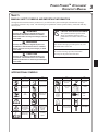
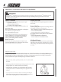
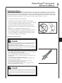
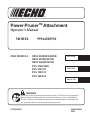
Power PrunerTM Attachment
Operator's Manual
MODEL
FOR MODELS
99944200530
SRM-2100SB/2400SB
SRM-210SB/211SB
SRM-260SB/261SB
PAS 2100/2400
PAS 210/211
PAS 230/231
PAS 260/261
ENGLISH
ESPAÑOL
FRANCAIS
WARNING
Read rules for safe operation and instructions carefully. ECHO provides an Operator's
Manual and a Safety Manual for Pro Attachment Series power source or Split Boom
Trimmer. Those manuals and this manual must be read and understood for proper and
safe operation, otherwise serious personal injury may result.
X7502302205
89865124565
02/07
2
INTRODUCTION
Welcome to the ECHO family. This ECHO product was designed and manufactured to provide long life and onthe-job-dependability. Read and understand this manual and the SAFETY MANUAL you found in the same
package. You will find both easy to use and full of helpful operating tips and SAFETY messages.
THE OPERATOR'S MANUAL
Read and understand this manual before operation. Keep it in a safe
place for future reference. It contains specifications and information for
operation, starting, stopping, maintenance, storage and assembly
specific to this product.
THE ATTACHMENT OPERATOR'S MANUAL
Read and understand this manual before operation. Keep it in a safe
place for future reference. It contains specifications and information for
operation and maintenance specific to the attachment.
THE SAFETY MANUAL
(If available for attachment)
Explains possible hazards and what measures you should take to insure
safe operation.
TABLE OF CONTENTS
Introduction ............................................................... 2
- The Operator's Manual ................................... 2
- The Safety Manual .......................................... 2
Safety ........................................................................ 3
- Manual Safety Symbols and Important
Information ...................................................... 3
- International Symbols ..................................... 3
- Personal Condition and Safety Equipment ...... 4
- Kickback .......................................................... 6
- Equipment ....................................................... 7
Description ................................................................ 7
Contents .................................................................... 8
Assembly ................................................................... 8
- Power Head Shaft/Lower Shaft Assembly .......... 8
- Front Handle Removal ........................................ 9
- Saw Chain Tension Adjustment ......................... 9
Operation ................................................................. 10
- Lubricating the Guide Bar and Saw Chain ........ 10
- Adjusting Automatice Oiler .............................. 10
- Pruning Techniques ......................................... 11
CopyRight© 2007 By Echo, Incorporated
All Rights Reserved.
Maintenance ............................................................ 12
- Skill Levels ........................................................ 12
- Maintenance Intervals ...................................... 12
- Lubrication ........................................................ 12
- Guide Bar and Saw Chain Replacement ............ 13
- Filing Saw Chain ............................................... 15
Storage ..................................................................... 17
Specifications ........................................................... 17
Servicing Information ............................................... 20
- Parts/Serial Number ................................................. 20
- Service .............................................................. 20
- ECHO Consumer Product Support .......................... 20
- Warranty Card .................................................. 20
- Manual Ordering Instructions .......................... 20
Specifications, descriptions and illustrative material in
this literature are as accurate as known at the time of
publication, but are subject to change without notice.
Illustrations may include optional equipment and
accessories, and may not include all standard equipment.
POWER PRUNERTM ATTACHMENT
OPERATOR'S MANUAL
SAFETY
MANUAL SAFETY SYMBOLS AND IMPORTANT INFORMATION
Throughout this manual and on the product itself, you will find safety alerts and helpful, informational messages
preceded by symbols or key words. The following is an explanation of those symbols and key words and what they
mean to you.
CIRCLE AND SLASH SYMBOL
DANGER
The safety alert symbol accompanied by the word
“DANGER” calls attention to an act or condition
which WILL lead to serious personal injury or death
if not avoided.
WARNING
The safety alert symbol accompanied by the word
“WARNING” calls attention to an act or condition
which CAN lead to serious personal injury or death
if not avoided.
CAUTION
This symbol means the specific action
shown is prohibited. Ignoring these
prohibitions can result in serious or fatal
injury.
NOTE
This enclosed message provides tips for use, care
and maintenance of the unit.
IMPORTANT
The enclosed message provides information
necessary for the protection of the unit.
The safety alert symbol accompanied by the word
“CAUTION” calls attention to an act or condition
which may lead to minor or moderate personal injury
if not avoided.
INTERNATIONAL SYMBOLS
Symbol form/shape
Symbol
description/application
Symbol form/shape
Symbol
description/application
Read and understand
Operator's Manual.
Fuel and oil mixture
Wear eyes, ears and
head protection
Finger Severing
Hot
Surface
Safety/Alert
Wear hand
protection. Use
two handed.
DO NOT smoke
near fuel.
Avoid all power
lines. This unit is
not insulated
against electrical
current.
Do not operate
closer than 15 M
(50 ft.) from
electrical
hazards.
Keep bystanders
at least 15 meters
(50 feet) away.
Plan retreat path
from falling
objects.
Symbol form/shape
Symbol
description/application
DO NOT allow
flames or sparks
near fuel.
Engine choke
control.
Emergency stop
Symbol form/shape
Symbol
description/application
Wear slip
resistant foot
wear.
Ignition
ON/OFF
Primer
bulb
Chain lubrication
Carburetor adjustment
- Low speed mixture
Carburetor adjustment
- High speed mixture
Carburetor adjustment
- Idle speed
3
4
PERSONAL CONDITION AND SAFETY EQUIPMENT
WARNING
Power PrunerTM Attachment users risk injury to themselves and others if the Power PrunerTM Attachment is used
improperly and or safety precautions are not followed. Proper clothing and safety gear must be worn when
operating a Power PrunerTM.
Physical Condition
Hearing Protection
Your judgment and physical dexterity may not be good:
• if you are tired or sick,
• if you are taking medication,
• if you have taken alcohol or drugs.
Operate unit only if you are physically and mentally well.
ECHO recommends wearing hearing protection whenever
unit is used.
Eye Protection
Wear eye protection that meets ANSI Z87.1 or CE requirements whenever you operate the unit
Face and Head Protection
When trimming overhead, always wear head protection
meeting ANSI Z89.1 or CE requirements with a full face
shield. Head protection with full face shield will help
protect you from falling branches and debris.
Hand Protection
Wear no-slip, heavy duty work gloves to improve your
grip on the unit handles. Gloves also reduce the transmission of machine vibration to your hands.
Proper Clothing
Wear snug fitting, durable protective clothing; chain saw
safety pants or chaps are recommended.
• Pants should have long legs, shirts with long sleeves.
• DO NOT WEAR SHORTS,
• DO NOT WEAR TIES, SCARVES, JEWELRY.
Wear sturdy protective safety shoes or boots with nonskid soles;
• DO NOT WEAR OPEN TOED SHOES,
• DO NOT OPERATE UNIT BAREFOOTED.
Hot Humid Weather
Heavy protective clothing can increase operator fatigue,
which may lead to heat stroke. Schedule heavy work for
early morning or late afternoon hours when temperatures
are cooler.
Vibration and Cold -It is believed that a condition called Raynaud’s Phenomenon, which affects the fingers of certain individuals may be
brought about by exposure to vibration and cold. Exposure to vibration and cold may cause tingling and burning sensations followed by loss of color and numbness in the fingers. The following precautions are strongly recommended
because the minimum exposure which might trigger the ailment is unknown.
• Keep your body warm, especially the head, neck, feet, ankles, hands
and wrists.
• Maintain good blood circulation by performing vigorous armexercises
during frequent work breaks and also by not smoking.
• Limit the hours of operation. Try to fill each day with jobs where
operating the trimmer or other hand-held power equipment is not
required.
• If you experience discomfort, redness and swelling of the fingers
followed by whitening and loss of feeling, consult your physician
before further exposing yourself to cold and vibration.
POWER PRUNERTM ATTACHMENT
OPERATOR'S MANUAL
Repetitive Stress Injuries -It is believed that overusing the muscles and tendons of the fingers, hands, arms and shoulders may cause soreness,
swelling, numbness, weakness and extreme pain in those areas. Certain repetitive hand activities may put you at a high
risk for developing a Repetitive Stress Injury (RSI). An extreme RSI condition is Carpal Tunnel Syndrome (CTS), which
could occur when your wrist swells and squeezes a vital nerve that runs through the area. Some believe that prolonged
exposure to vibration may contribute to CTS. CTS can cause severe pain for months or even years.
To reduce the risk of RSI/CTS, do the following:
• Avoid using your wrist in a bent, extended or twisted position.
Instead try to maintain a straight wrist position. Also, when grasping,
use your whole hand, not just the thumb and index finger.
• Take periodic breaks to minimize repetition and rest your hands.
• Reduce the speed and force with which you do the repetitive movement.
• Do exercises to strengthen the hand and arm muscles.
• Immediately stop using all power equipment and consult a doctor if
you feel tingling, numbness or pain in the fingers, hands, wrists or
arms. The sooner RSI/CTS is diagnosed,the more likely permanent
nerve and muscle damage can be prevented.
Guide Bar and Saw Chain
DANGER
• Serious injury may result from the use of non approved guide bar
and saw chain combinations. Read and comply with all safety
instructions listed in this manual.
• ECHO, INC. will not be responsible for the failure of cutting
devices or accessories which have not been tested and approved
by ECHO for use with this unit.
• Never adjust the guide bar or saw chain when the engine is operating.
• Check that the cutting attachment, guide bar and saw chain is firmly
attached and in safe operating condition.
• Only use ECHO approved guide bar and saw chain.
• Do not hit rocks, stones, tree stumps and other foreign objects with
the saw chain.
• Do not cut into the ground with the saw chain.
• If saw chain strikes an obstruction, stop engine immediately and
inspect saw chain for damage.
• Do not operate with a dull, broken or discolored saw chain.
• Remove all foreign objects from work area.
• Always cover the guide bar and saw chain with guide bar cover
during transportation and in storage.
DANGER
All over head electrical conductors and communications wires can
have electricity flow with high voltages. Never touch wires directly
or indirectly when pruning, otherwise serious injury or death may
result.
5
6
Read the Manuals
• Provide all operators of this equipment with the Operator's Manual,
and instructions for safe operation.
Clear the Work Area
• Spectators and fellow workers must be warned, and children and
animals prevented from coming nearer than 15 m (50 ft.) while the unit
is in use.
Use Proper Clothing & Equipment
• Always wear head protection with full face shield to help protect
against falling branches and debris.
Keep A Firm Grip
• Hold the front and rear handles with both hands with thumbs and
fingers encircling the handles
Keep A Solid Stance
• Maintain footing and balance at all times. Do not stand on slippery,
uneven or unstable surfaces. Do not work in odd positions or on
ladders. Do not overreach.
• Operate the Power PrunerTM only from the ground or out of an
approved bucket lift.
• Always evaluate the branches to be pruned for hazards such as loose
dead branches which may fall and strike the operator or helpers.
Remove hazards before pruning.
• Plan retreat path from falling objects.
• Cut branches bounce when striking ground.
• Turn the Power PrunerTM off when moving from tree to tree.
• Avoid any contact with saw chain.
Avoid Hot Surfaces
• Keep exhaust area clear of flammable debris. Avoid contact during
and immediately after operation.
KICKBACK
DANGER
Kickback can lead to dangerous loss of control of the Power
PrunerTM and result in serious injury to the operator or any one
standing close by. Hold the Power PrunerTM firmly with both hands
with thumbs and fingers encircling the front and rear handles. Be
aware of the down and outward path the pruner will take after the
cut is made.
Kickback may occur when the moving saw chain at the nose or tip of
the guide bar touches an object, or when the wood closes in and
pinches the saw chain in the cut. In some cases this may cause a
lightning-fast reverse action, kicking the guide bar and saw chain up
and back or down and back towards the operator. Either of these
reactions may cause the operator to lose control of the Power PrunerTM
which could result in serious personal injury.
With a basic understanding of kickback, you can reduce or eliminate the
element of surprise which contributes to accidents.
Avoid contact of the guide bar tip with any object while the saw chain
is moving.
POWER PRUNERTM ATTACHMENT
OPERATOR'S MANUAL
Cut only wood. Avoid striking concrete, metal, wire, or other obstructions which could cause kickback or damage to the saw chain.
If the saw chain does strike a foreign object, immediately stop the
engine, inspect and repair the Power PrunerTM if necessary.
EQUIPMENT
Before operation a complete check of the unit must be performed;
• Check unit for loose/missing nuts, bolts and screws. Tighten and/or replace as needed.
DESCRIPTION
Locate this safety decal on your attachment. Make sure the decal is legible and that you understand and follow the
instructions on it. If it cannot be read, a new one can be ordered from your ECHO dealer. See PARTS ORDERING
instructions for specific information.
5
6
1
3
4
2
9
7
8
1.
2.
3.
4.
5.
6.
P/N 89016022660
GRIP, FRONT - Cushioned grip for left hand.
SHAFT DECAL - Contain important safety information that must be followed.
LOWER DRIVE SHAFT ASSEMBLY - Contains a specially designed liner and the flexible drive shaft.
CUTTING ATTACHMENT - Sealed, gear ratio is 1.5:1 reduction.
AUTOMATIC OILER ASSEMBLY - Self oiling. Use high quality, low viscosity, non detergent bar and chain oil.
SAW CHAIN - 91 VX 9.53mm (3/8 inch) low profile Oregon® saw chain. Runs approximately 609.6 m/min.
(2000 ft/min) at full throttle.
7. GUIDE BAR - 254 mm (10 inch) Bar
8. CUTTING SHOE - Used to capture and stabilize branch while cutting. Place cutting shoe against branch, accelerate
and lower saw chain into branch.
9. GUIDE BAR COVER - Used to cover guide bar and saw chain during transport and storage. Remove guide bar cover
before using unit.
7
8
CONTENTS
The ECHO product you purchased has been factory pre-assembled for your convenience. After opening the carton,
check for damage. Immediately notify your retailer or ECHO Dealer of damaged or missing parts. Use the contents list to
check for missing parts.
1-
Power PrunerTM Attachment
Plastic Bag (co-pack)
Operators Manual
Safety Manual
Warranty Registration Card
Guide Bar Cover
Safety Glasses
Storage Hook Assembly
ASSEMBLY
POWER HEAD SHAFT/LOWER SHAFT ASSEMBLY
B
D
Tools Required: None
Parts Required: PAS or SRM-SB Power Head w/Shaft & Coupling.
1. Set Power Head/Shaft Assembly on a level surface.
2. Pull locator pin (A) out, and turn counter-clockwise 1/4 turn to lockout position.
3. Remove vinyl cap from attachment drive shaft.
A
D
C
4. Carefully fit attachment drive shaft assembly into coupler (B) to
decal assembly line (C), making sure that the inner lower drive shaft
engages into the square upper drive shaft socket.
NOTE
Earlier model Power Heads may have shorter couplings. Short
couplings fit flush to decal point (E). New couplings are 4-3/4 in.
long, and fit flush to line (C).
NOTE
Lower bearing housing and head assembly must be in line with the
engine.
E
POWER PRUNERTM ATTACHMENT
OPERATOR'S MANUAL
5. Rotate locator pin (A) 1/4 turn clockwise to engage lower shaft
hole. Insure locator pin is fully engaged by twisting lower drive
shaft. Locator pin should snap flush in coupler. Full engagement will
prevent further shaft rotation.
6. Secure lower shaft assembly to coupler by tightening clamping
knob (D).
FRONT LOOP HANDLE REMOVAL
Tools Required: Screwdriver.
Parts Required: None
NOTE
Front loop handles/loop handles with barrier bars are not recommended for use with Power Pruner attachment.
1. Remove front handle assembly, barrier bar (if installed), and mounting hardware from PAS or SRM-SB power head.
2. Retain parts for future use.
SAW CHAIN TENSION ADJUSTMENT
Tools Required: 10 mm (13/32 in.) Wrench, Screwdriver
WARNING
Always wear gloves when handling saw chain, otherwise serious
personal injury may result.
To Adjust Saw Chain Tension.
1. Loosen two (2) 6 mm guide bar nuts (A) located on cutting attachment.
2. Turn the adjuster slot (B) clockwise until saw chain touches the
bottom of guide bar. Turning adjuster slot (B) counter clockwise will
loosen saw chain on guide bar.
3. Tighten guide bar nuts firmly. Move saw chain backwards on guide
bar by hand. Saw chain should move freely on guide bar if it is in
proper mesh with sprocket. If saw chain is difficult to rotate or binds
on guide bar, it is too tight.
Keep the saw chain lubricated and properly adjusted and the guide bar
nuts tightened firmly at all times.
A
B
9
10
OPERATION
NOTE
Refer to your Pro Attachment Series power source or Split Boom
Operator's Manual for correct engine fueling, starting and stopping
instructions.
IMPORTANT
Guide bar cover is for travel/storage only. Remove cover before
using unit.
LUBRICATING THE GUIDE BAR AND SAW
CHAIN
Automatic Oiling System
1. Wipe debris from around oil fill cap.
2. Remove oil fill cap and fill reservoir with a quality, low viscosity
guide bar and saw chain oil.
NOTE
The discharge volume of the automatic oiler is preset to deliver 3 to
4 cc/min. at normal operating RPM. During heavy or dry cutting
conditions the oil discharge volume may be adjusted to assure
adequate lubrication. Refill the oil reservoir with each tank of fuel.
IMPORTANT
To prevent plastic deterioration, do not use synthetic or silicone
based oil.
ADJUSTING AUTOMATIC OILER
Tools required: 10 mm (13/32 in.) Wrench, Screwdriver
1. Remove two (2) 10 mm guide bar retaining nuts and sprocket
cover.
2. From bottom of gear case, turn adjustment screw (A) clockwise to
decrease oil volume - counter clockwise to increase oil volume.
NOTE
Very little visible oil on the saw chain will provide sufficient
lubrication.
A
POWER PRUNERTM ATTACHMENT
OPERATOR'S MANUAL
PRUNING TECHNIQUES
The Power Pruner™ Attachment is designed for light to medium
trimming of limbs and branches up to 203 mm (8 in.) in diameter.
Follow these tips for successful operation.
CORRECT
• Plan cut carefully. Check direction branch will fall.
• Long branches should be removed in several pieces.
• Do not stand directly beneath branch being cut.
• When ready to cut:
Hold "cutting shoe" against branch. This will prevent whipping of the
branch. DO NOT use back and forth sawing action.
GUIDE AGAINST
BRANCH
NOT
CORRECT
• Look out for branches immediately behind the branch being cut. If
saw chain hits rear branch, damage to the saw chain my occur.
• Accelerate to full throttle.
• Apply cutting pressure.
BLADE HITS REAR BRANCH
• Ease cutting pressure when nearing end of cut to maintain control.
• When pruning a limb 102 mm (4 in.) diameter or larger cut as follows:
1. Under cut 1/4 limb diameter near tree trunk.
2. Finish top cut slightly farther out on limb.
3. Flush cut stub at trunk.
• DO NOT use for felling or bucking.
NOT
CORRECT
11
12
MAINTENANCE
Your ECHO Pruner attachment is designed to provide many hours of trouble free service. Regular scheduled maintenance
will help your Pruner attachment achieve that goal. If you are unsure or are not equipped with the necessary tools, you
may want to take your unit to an ECHO Service Dealer for maintenance. To help you decide whether you want to DO-ITYOURSELF or have the ECHO Dealer do it, each maintenance task has been graded. If the task is not listed, see your
ECHO Dealer for repairs.
SKILL LEVELS
Level 1 =
Level 2 =
Level 3 =
Easy to do. Most required tools come with unit.
Moderate difficulty. Some specialized tools may be required.
Experience required. Specialized tools are required. ECHO recommends
the unit be returned to your ECHO Dealer for service.
MAINTENANCE INTERVALS
Component/System
Maintenance Procedure
Drive Shaft
Guide Bar
Saw Chain
Screws/Nuts/Bolts
Grease
Inspect/Replace/Lubricate
Inspect/Sharpen/Replace/Lubricate
Inspect/Tighten/Replace
Skill Level
1
2
2
1
Frequency
Every 25 hours of use
Before each use
Before each use
Before each use
LUBRICATION
Drive Shaft (Lower)
Level 1
Tools Required: 4 mm L-Wrench
Parts Required: ECHO® LUBETM 8 oz. (P/N 91014) or Lithium Base
Grease.
IMPORTANT
Lower and upper drive shaft must be lubricated with high temperature automotive grease every 25 hours of operation, otherwise
drive shaft assembly overheating and failure can result.
A
1. Remove the cutting attachment from the Power PrunerTM shaft
housing by removing the location bolt (B), loosening the (4) four
bolts (A) clamping the cutting attachment to the shaft housing,
and slide the cutting attachment off.
2. Remove lower flex cable, wipe clean, and apply a thin coat 15ml
(1/2 oz.) of high temperature automotive grease.
B
POWER PRUNERTM ATTACHMENT
OPERATOR'S MANUAL
3. Slide the cutting attachment onto the shaft housing until the hole
in the neck of the cutting attachment is aligned with the hole (C) in
the housing (It may be necessary to rotate the saw chain slightly
to align the internal pinion and drive shaft.)
4. Insert location bolt (B) into hole (C) and tighten to snug.
5. Tighten bolts (A), clamping the cutting attachment onto the
housing.
C
B
GUIDE BAR AND SAW CHAIN REPLACEMENT
WARNING
Never try to replace or adjust guide bar and saw chain with engine running. Always disconnect spark plug wire
before servicing guide bar and saw chain. This saw chain is VERY sharp, wear heavy gloves to protect your hands
when handling it. Wear eye protection meeting CE or ANSI specification Z87.1.
Guide Bar Replacement / Installation
Level 2
Tools Required: 10 x 19 mm (13/32 x 3/4 in.) T-wrench
1. Remove two (2) 6 mm guide bar nuts (A), and turn saw chain tension
adjustment slot (B) counterclockwise to release tension.
2. Remove sprocket cover (C).
3. Remove guide bar and saw chain from gear case and sprocket.
4. Remove chain from guide bar and check guide bar for damage and
excessive or uneven wear. Replace guide bar if necessary.
C
A
B
13
14
5. Turn saw chain tension adjuster slot (B) counterclockwise until it
stops.
D
B
6. Install chain on guide bar with cutters on top of bar facing toward
bar tip.
7. Install guide bar and chain on gear case, engaging chain with drive
sprocket (D).
8. Turn tension adjustment slot clockwise to take up slack in saw
chain.
C
D
9. Install sprocket guard (C), and tighten guide bar nuts finger tight.
10. Adjust chain tension.
To Adjust Saw Chain Tension.
1. Loosen two guide bar nuts (A), if necessary.
2. Turn saw chain adjuster slot (B) clockwise to tighten saw chain on
guide bar. Turning slot counter clockwise will loosen saw chain on
guide bar.
3. Tighten guide bar nuts (A) firmly. Pull the saw chain around the
guide bar by hand. Saw chain should move freely on guide bar. If
saw chain is difficult to rotate or binds on guide bar, it is too tight.
4.
Keep the saw chain lubricated and properly adjusted and the
guide bar nuts tightened firmly at all times.
A
B
E
POWER PRUNERTM ATTACHMENT
OPERATOR'S MANUAL
15
FILING SAW CHAIN
Level 3.
Tools Required: 4 mm (5/32 in.) round File
Flat File
Depth Gauge
IMPORTANT
Dull or damaged cutters will result in poor cutting performance,
increased vibration and premature chain failure.
30°
1
WARNING
Always stop engine and wear gloves when filing saw chain,
otherwise serious personal injury may result.
2
1. Set round file (A) in cutter at 30° angle. One fifth (1/5) of the file
should be exposed above top cutter edge.
2. Keep file horizontal in cutter and file in one direction.
90°
3
3. File until cutter top and side bevel edges are sharp without nicks.
4. Place depth gauge tool (B) firmly on top of cutter with .025" slot
and end against front cutter raker. File cutter raker with flat file
until flush with top of depth gauge.
4
5. Finish cutter sharpening by rounding front raker edge (C) with flat
file.
5
6. Properly filed cutter is as shown.
6
(TOP PLATE ANGLE)
7. Apply clean oil and rotate saw chain slowly to wash away filings.
8. If saw chain is coated or clogged with resin, clean in kerosene then
soak in oil.
(TOP PLATE CUTTING ANGLE)
(DEPTH GAUGE)
16
Standard Bar and Chain Combinations
Bar P/N
Chain P/N
chain type
links
pitch
gauge
PPF-210
PPT-230
99944200530
10" Intenz™ bar
1102373901
1917039
91
39
3/8"
0.050
PPT-260
12" Intenz™ bar
1122374401
1917044
91
44
3/8"
0.050
Optional Bar and Chain Combinations
PPF-210
99944200530
PPT-230
PPT-260
Bar P/N
8" regular bar
1080373301
10" regular bar
1101373901
10" narrow bar
1100373901
10" regular bar
1101373901
10" narrow bar
1100373901
12" regular bar
1121374401
12" narrow bar
1120374401
Chain P/N
chain type
links
pitch
gauge
1917033
91
33
3/8"
0.050
1917039
91
39
3/8"
0.050
1907039
90
39
3/8"
0.043
1917039
91
39
3/8"
0.050
1907039
91
39
3/8"
0.050
1917044
91
44
3/8"
0.050
1907044
90
44
3/8"
0.043
When converting from Intenz™ guide bar to regular or narrow kerf guide bar, see your Echo dealer for
additional parts needed.
IMPORTANT
Chain and guide bar gauge size must be identical. Use Bar/Chain combinations shown in table above.
POWER PRUNERTM ATTACHMENT
OPERATOR'S MANUAL
STORAGE
Storage Hook Installation
1. Insert small end of hook into locating hole on attachment shaft.
2. Slide plastic cap onto end of attachment shaft.
SPECIFICATIONS
MODEL ----------------------------------------------------- 99944200530 POWER PRUNERTM ATTACHMENT
Length ------------------------------------------------------- 1448 mm (57.0 in.)
Width -------------------------------------------------------- 102 mm (4.0 in.)
Height ------------------------------------------------------- 140 mm (5.5 in.)
Weight ------------------------------------------------------ 2.19 kg (4.84 lbs.)
Sprocket Type ---------------------------------------------- 6 tooth spur, 9.53 (3/8 in.) pitch
Drive Shaft -------------------------------------------------- 1/4 in. Flex Cable
Gear Reduction Ratio -------------------------------------- 1.5:1
Oiling System ----------------------------------------------- Automatic
Handle ------------------------------------------------------- Left foam grip
Guide Bar and Saw Chain --------------------------------- 254 mm (10 in.), 9.53 mm (3/8 in.) pitch, .050 in. gauge, 91 VX
chain.
17
18
NOTES
POWER PRUNERTM ATTACHMENT
OPERATOR'S MANUAL
NOTES
19
SERVICING INFORMATION
PARTS/SERIAL NUMBER
Genuine ECHO Parts and ECHO REPOWER™ Parts and Assemblies for
your ECHO products are available only from an Authorized ECHO
Dealer. When you do need to buy parts always have the Model
Number and Serial Number of the attachment with you. You can find
these numbers on the driveshaft model/serial number label. For future
reference, write them in the space provided below.
Model No. ____________SN.__________
SERVICE
Service of this product during the warranty period must be performed
by an Authorized ECHO Service Dealer. For the name and address of
the Authorized ECHO Service Dealer nearest you, ask your retailer or
call: 1-800-432-ECHO (3246). When presenting your unit for Warranty
service/repairs, proof of purchase is required.
DEALER?
Call
1-800-432-ECHO
or
www.echo-usa.com
ECHO CONSUMER PRODUCT SUPPORT
If you require assistance or have questions concerning the application,
operation or maintenance of this product you may call the ECHO
Consumer Product Support Department at 1-800-673-1558 from 8:30 am
to 4:30 pm (Central Standard Time) Monday through Friday. Before
calling, please know the model and serial number of your unit to help
your Consumer Product Support Representative.
CONSUMER PRODUCT
SUPPORT
1-800-673-1558
8:30 - 4:30 Mon - Fri C.S.T.
WARRANTY REGISTRATION
To ensure trouble free warranty coverage it is important that you
register your ECHO equipment on-line at www.echo-usa.com. Other
registration options are by automated phone at 1-800-432-3246 or by
filling out the warranty registration card supplied with your unit.
Registering your product confirms your warranty coverage and
provides a direct link between you and ECHO if we find it necessary to
contact you.
ADDITIONAL OR REPLACEMENT MANUALS
Safety Manuals in English/Spanish or English/French are available, free of charge, from your ECHO dealer or at
www.echo-usa.com.
Operator's and Parts Manuals are available by:
• Downloading free from www.echo-usa.com
• Purchasing from your Echo Dealer.
• Manuals are available by sending a written request stating the model number and serial number of your Echo unit, part
number of the manual, your name and address, and mail to the address below.
Safety Videos are available from your Echo dealer. A $5.00 shipping charge will be required for each video.
ECHO, INCORPORATED
400 OAKWOOD ROAD
LAKE ZURICH, IL 60047-1564
WWW.ECHO-USA.COM
008666/999999