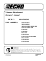
1
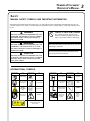
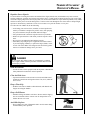
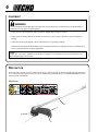
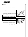
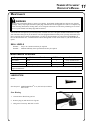
Trimmer Attachment
Operator's Manual
MODEL99944200540
FOR MODELS:
SRM-2100SB
SRM-2400SB
SRM-210SB/211SB/225SB
SRM-260SB/261SB
PAS-2100
PAS-2400
PAS-2601
PAS-210/211
PAS-225/225VP/225VPB
PAS-230/231
PAS-260/261
PAS-265/266
WARNING
Users of this equipment risk injury to themselves and others if the unit is used improperly and/or safety precautions are not followed. ECHO provides an operator’s
manual. It must be read and understood for proper and safe operation. Failure to do
so could result in serious injury.
X7532279104
89865062334
04/11
2
Introduction
Welcome to the ECHO family. This ECHO product was designed and manufactured to provide long life and on-the-job
dependability. Read and understand this manual and the SAFETY MANUAL before operation. You will find both easy
to use and full of helpful operating tips and SAFETY messages.
the operator's manual
Read and understand this manual before operation. Keep it in a safe
place for future reference. It contains specifications and information for
operation and maintenance specific to the attachment.
the safety manual
Explains possible hazards and what measures you should take to insure
safe operation.
Table of Contents
Introduction.....................................................................2
- The Operator's Manual............................................2
- The Safety Manual...................................................2
Safety..............................................................................3
- Manual Safety Symbols & Important Information..3
- International Symbols..............................................3
- Personal Condition and Safety Equipment..............4
- Equipment................................................................6
Description......................................................................6
Contents..........................................................................7
Assembly........................................................................8
- Power Head Shaft / Lower Shaft Assembly............8
- To Advance Trimmer Line.......................................9
- Remove Nylon Line Head.......................................9
Operation.......................................................................10
- To Advance Trimmer Line.....................................10
Copyright© 2011 By Echo, Incorporated
All Rights Reserved.
Maintenance..................................................................11
- Skill Levels............................................................11
- Maintenance Intervals............................................11
- Lubrication.............................................................11
- Nylon Line Replacement.......................................12
Storage..........................................................................13
Specifications................................................................13
Servicing Information...................................................16
- Parts/Serial Number ................................................16
- Service...................................................................16
- ECHO Consumer Product Support........................16
- Warranty Card........................................................16
- Additional or Replacement Manuals.....................16
Specifications, descriptions and illustrative material in
this literature are as accurate as known at the time of
publication, but are subject to change without notice.
Illustrations may include optional equipment and
accessories, and may not include all standard equipment.
Trimmer Attachment
Operator's Manual
3
Safety
manual safety symbols and important information
Throughout this manual and on the product itself, you will find safety alerts and helpful, informational messages preceded by symbols or key words. The following is an explanation of those symbols and key words and what they mean
to you.
Circle and slash symbol
DANGER
The safety alert symbol accompanied by the word
“DANGER” calls attention to an act or condition
which WILL lead to serious personal injury or
death if not avoided.
WARNING
The safety alert symbol accompanied by the word
“WARNING” calls attention to an act or condition which CAN lead to serious personal injury or
death if not avoided.
CAUTION
The safety alert symbol accompanied by the word
“CAUTION” calls attention to an act or condition
which may lead to minor or moderate personal
injury if not avoided.
This symbol means the specific action
shown is prohibited. Ignoring these prohibitions can result in serious or fatal injury.
NOTE
This enclosed message provides tips for use, care and
maintenance of the unit.
IMPORTANT
The enclosed message provides information necessary for the protection of the unit.
international symbols
Symbol form/shape
Symbol
description/application
"WARNING, SEE OPERATOR'S MANUAL
Wear eyes, ears and
head protection
Rotating
Cutting Attachment
Wear hand and
foot protection
Symbol form/shape
Symbol
description/application
Hot
Surface
Symbol form/shape
Symbol
description/application
Carburetor adjustment
- High speed mixture
Fuel and oil mixture
Carburetor adjustment
- Idle speed
Emergency stop
Carburetor adjustment
- Low speed mixture
WARNING
Keep bystanders and helpers
away 15 m (50 ft.).
DO NOT USE
BLADES - Line
Head Only
Symbol form/shape
Symbol
description/application
Primer Bulb
Ignition
ON/OFF
Engine choke
control.
Beware
- Thrown,
Ricochet
objects
4
personal condition and safety equipment
WARNING
Users of this product risk injury to themselves and others if the unit is used improperly and/or safety precautions are
not followed. Proper clothing and safety gear must be worn when operating unit.
Physical Condition
Your judgment and physical dexterity may not be good:
• if you are tired or sick,
• if you are taking medication,
• if you have taken alcohol or drugs.
Operate unit only if you are physically and mentally
well.
Eye Protection
Wear eye protection that meets ANSI Z87.1 or CE requirements whenever you operate the unit.
Proper Clothing
Wear snug fitting, durable clothing;
• Pants should have long legs, shirts with long
sleeves.
• DO NOT WEAR SHORTS,
• DO NOT WEAR TIES, SCARVES, JEWELRY,
or clothing with loose or hanging items that could
become entangled in moving parts or surrounding
growth.
Hand Protection
Wear no-slip, heavy-duty work gloves to improve your
grip on the handle. Gloves also reduce the transmission
of machine vibration to your hands.
Wear sturdy work shoes with nonskid soles;
• DO NOT WEAR OPEN TOED SHOES,
• DO NOT OPERATE UNIT BAREFOOTED.
Wear no-slip, heavy duty work gloves.
Keep long hair away from engine and air intake. Retain
hair with cap or net.
Hearing Protection
Hot Humid Weather
ECHO recommends wearing hearing protection whenever unit is used.
Heavy protective clothing can increase operator fatigue
which may lead to heat stroke. Schedule heavy work for
early morning or late afternoon hours when temperatures
are cooler.
Extended Operation/Extreme Conditions
It is believed that a condition called Raynaud’s Phenomenon, which affects the fingers of certain individuals, may be
brought about by exposure to vibration and cold. Exposure to vibration and cold may cause tingling and burning sensations, followed by loss of color and numbness in the fingers. The following precautions are strongly recommended,
because the minimum exposure, which might trigger the ailment, is unknown.
• Keep your body warm, especially the head, neck, feet, ankles,
hands, and wrists.
• Maintain good blood circulation by performing vigorous arm exercises during frequent work breaks, and also by not smoking.
• Limit the hours of operation. Try to fill each day with jobs where
operating the unit or other hand-held power equipment is not
required.
• If you experience discomfort, redness, and swelling of the fingers
followed by whitening and loss of feeling, consult your physician
before further exposing yourself to cold and vibration.
Trimmer Attachment
Operator's Manual
Repetitive Stress Injuries
5
It is believed that overusing the muscles and tendons of the fingers, hands, arms, and shoulders may cause soreness,
swelling, numbness, weakness, and extreme pain in those areas. Certain repetitive hand activities may put you at a high
risk for developing a Repetitive Stress Injury (RSI). An extreme RSI condition is Carpal Tunnel Syndrome (CTS), which
could occur when your wrist swells and squeezes a vital nerve that runs through the area. Some believe that prolonged
exposure to vibration may contribute to CTS. CTS can cause severe pain for months or even years.
To reduce the risk of RSI/CTS, do the following:
• Avoid using your wrist in a bent, extended, or twisted position. Instead try to maintain a straight wrist position. Also, when grasping,
use your whole hand, not just the thumb and index finger.
• Take periodic breaks to minimize repetition and rest your hands.
• Reduce the speed and force with which you do the repetitive movement.
• Do exercise to strengthen the hand and arm muscles.
• Immediately stop using all power equipment and consult a doctor
if you feel tingling, numbness, or pain in the fingers, hands, wrists,
or arms. The sooner RSI/CTS is diagnosed, the more likely permanent nerve and muscle damage can be prevented.
danger
Do not operate this product indoors or in inadequately ventilated
areas. Engine exhaust contains poisonous emissions and can cause
serious injury or death.
Read the Manuals
• Provide all users of this equipment with the Operator’s Manual and
Safety Manual for instructions on Safe Operation.
Clear the Work Area
• Spectators and fellow workers must be warned, and children and
animals prevented from coming nearer than 15 m (50 ft.) while the
unit is in use.
Keep a Firm Grip
• Hold the front and rear handles with both hands, with thumbs and
fingers encircling the handles.
Keep a Solid Stance
• Maintain footing and balance at all times. Do not stand on slippery,
uneven or unstable surfaces. Do not work in odd positions or on
ladders. Do not over reach.
Avoid Hot Surfaces
• Keep exhaust area clear of flammable debris. Avoid contact during
and immediately after operation.
6
equipment
warning
Use this attachment with ECHO approved models only. Serious injury may result from the use of this attachment
combined with a non approved ECHO product.
• Check unit for loose/missing nuts, bolts, and screws. Tighten and/or replace as needed.
• Inspect shield for damage and ensure that the cut-off knife is securely in place. Replace if either is damaged or
missing.
• Check that the cutting attachment is firmly attached and in safe operating condition.
• Check that front loop handle and shoulder strap/ or shoulder/waist harness are adjusted for safe, comfortable operation. See Assembly Section for proper adjustment.
NOTE
ECHO, INC. will not be responsible for the failure of cutting devices, attachments or accessories which have not
been tested and approved by ECHO.
Description
Locate this safety decal on your unit. Make sure the decal is legible and that you understand and follow the instructions
on it. If the decal cannot be read, a new one can be ordered from your ECHO dealer. See PARTS ORDERING instructions for specific information.
Shaft Decal
1
4
2
3
Trimmer Attachment
Operator's Manual
7
1. Drive Shaft Assembly - Contains a specially designed liner and the flexible drive shaft.
2. NYLON CUTTING ATTACHMENT - Contains replaceable nylon trimming line that advances when the trimmer
head is tapped against the ground while the head is turning at normal operating speed.
3. CUT-OFF KNIFE - Automatically trims line to the correct length: 5 in. after head is tapped on the ground. If trimmer is operated without a cut-off knife the line will become too long, the engine will overheat, and engine damage
may occur.
4. PLASTIC DEBRIS SHIELD ASSEMBLY - Shield assembly includes the Cut-Off Knife. Helps protect the operator
by deflecting debris produced during the trimming operation. This shield must be replaced with the steel shield for
blade use.
Contents
The ECHO product you purchased has been factory pre-assembled for your convenience.
After opening the carton, check for damage. Immediately notify your retailer or ECHO Dealer of damaged or missing
parts. Use the contents list to check for missing parts.
_____ 1 -
_____ 1-
_____ 1-
_____ 1-
PAS Trimmer Attachment
Operator's Manual
Warranty Registration Card
Storage Hook Assembly
8
Assembly
power head shaft/lower shaft assembly
Parts Required: PAS or SRM-SB Power Head w/Shaft & Coupling.
1. Set Power Head/Shaft Assembly on a level surface.
B
2. Pull locator pin (A) out, and turn counter-clockwise 1/4 turn to lockout position.
D
3. Remove vinyl cap from attachment drive shaft.
4. Carefully fit attachment drive shaft assembly into coupler (B) to
decal assembly line (C), making sure that the inner lower drive shaft
engages into the square upper drive shaft socket.
C
E
A
NOTE
Earlier model Power Heads may have shorter couplings. Short
couplings fit flush to decal point (E). New couplings are 4-3/4 in.
long, and fit flush to line (C).
NOTE
Lower bearing housing and head assembly must be in line with the
engine.
5. Rotate locator pin (A) 1/4 turn clockwise to engage lower shaft hole. Insure locator pin is fully engaged by twisting lower drive
shaft. Locator pin should snap flush in coupler. Full engagement
will prevent further shaft rotation.
6. Secure lower shaft assembly to coupler by tightening clamping knob (D).
D
C
A
Trimmer Attachment
Operator's Manual
to advance trimmer line
See Maintenance Section for nylon line replacement.
NOTE
To advance trimmer line, tap trimmer head against the ground
while the head is turning at normal operating speed.
remove nylon line head
Caution
Wear Gloves or personal injury may result:
• Cutoff knife is sharp.
• Gearcase and surrounding area may be hot.
D
NOTE
Do not disassemble nylon line head.
1. Align locking hole in upper plate with notch in edge of gear housing and insert head locking tool (D).
2. Remove line head (E) by turning it clockwise until head is completely off of shaft.
3. Remove locking tool (D).
IMPORTANT
Semi-automatic nylon line heads must be used only with plastic
debris shield with cut-off knife. Using nylon line heads with
metal debris shield can result in trimmer damage, caused by operation with excessive line length.
E
9
10
Operation
WARNING
Moving parts can amputate fingers or cause severe injuries. Keep hands, clothing and loose objects away from all
openings. Always stop engine, disconnect spark plug, and make sure all moving parts have come to a complete stop
before removing obstructions, clearing debris, or servicing unit. Allow unit to cool before performing service. Wear
gloves to protect hands from sharp edges and hot surfaces.
warning
The attachment will operate immediately when the engine starts and could result in loss of control and possible
serious injury. Keep movable parts of the attachment off the ground and away from objects that could become
entangled or thrown.
NOTE
Refer to your Pro Attachment Series Operator's Manual for correct engine fueling, starting and stopping instructions.
NOTE
Refer to the Grass Trimmer / Brush Cutter Safety Manual for proper and safe trimming techniques.
warning
Inspect starting area for hazards such as rocks, glass, debris etc. which could be contacted by the cutting attachment when starting. Keep helpers and bystanders at least 15 m (50 ft.) from starting area, otherwise serious
personal injury may result.
Trimmer Attachment
Operator's Manual
Maintenance
WARNING
Moving parts can amputate fingers or cause severe injuries. Keep hands, clothing and loose objects away from all
openings. Always stop engine, disconnect spark plug, and make sure all moving parts have come to a complete stop
before removing obstructions, clearing debris, or servicing unit. Allow unit to cool before performing service. Wear
gloves to protect hands from sharp edges and hot surfaces.
Your ECHO unit is designed to provide many hours of trouble-free service. Regular scheduled maintenance will help
your unit achieve that goal. If you are unsure or are not equipped with the necessary tools, you may want to take your
unit to an ECHO Service Dealer for maintenance. To help you decide whether you want to DO-IT-YOURSELF or
have the ECHO Dealer do it, each maintenance task has been graded. If a task is not listed, see your ECHO Dealer for
repairs.
skill levels
Level 1 =
Level 2 =
Easy to do. Common tools may be required.
Moderate difficulty. Some specialized tools may be required.
maintenance intervals
Component
Maintenance Procedure
Skill Level
Interval
Drive Shaft
Grease
1
Every 25 hours of use
Gear Housing
Grease
1
Every 50 hours of use
Screws/Nuts/Bolts
Inspect/Tighten/Replace
1
Before Each Use
IMPORTANT - Time intervals shown are maximum. Actual use and your experience will determine the frequency of
required maintenance.
lubrication
Level 1.
Parts Required: POWER BLENDXTM 8 oz. (P/N 91014) or Lithium Base Grease.
Gear Housing
1. Clean all loose debris from gear box.
2. Remove plug (A) and check level of grease.
3. Add grease if necessary. DO NOT over-fill.
A
11
12
Drive Shaft (Lower)
IMPORTANT
Lower and upper drive shaft must be lubricated with high temperature automotive grease every 25 hours of operation, otherwise
drive shaft assembly overheating and failure can result.
1. Loosen two (2) screws (B) and remove center locating screw (C). Pull gear box and shield from drive shaft housing.
2. Pull flexible cable from the drive shaft housing, wipe clean and re-coat with a thin coating [15 ml (1/2 oz.)] of grease.
3. Slide the flexible cable back in the drive housing. DO NOT get dirt on the flex cable.
4. Install the gear housing and shield assembly.
IMPORTANT
Flat edge of washers (D) must be against drive shaft.
nylon line replacement
1. Cut one piece of line to recommended length.
.080 (2.0 mm) dia. – 10’ (3 m)
.095 (2.4 mm) dia. – 10’ (3 m)
2. Align arrows on top of knob with openings in eyelets.
3. Insert one end of trimmer line into an eyelet, and push line equal
distance through trimmer head.
4. Hold trimmer head while turning knob clockwise to wind line onto
spool until about 5” (13 cm) of each line remains exposed.
Trimmer head is now fully loaded and ready for operation.
NOTE:
Trimmer head is pre-wound with .095" (2.4mm) Crossfire™ trimmer
line.
C
B
D
Trimmer Attachment
Operator's Manual
Wear Indicators
IMPORTANT
Wear Indicators
When the wear indicators located at the bottom of the Speed-Feed® head are worn smooth, replacement of the cover or the
entire Speed-Feed® head is required.
Storage
Storage Hook Installation
1. Insert small end of hook into locating hole on attachment shaft.
2. Slide plastic cap onto end of attachment shaft.
Specifications
MODEL���������������������������������������������������� PAS Trimmer Attachment
Shaft Length������������������������������������������������ 870 mm (34.3 in.)
Attachment Width����������������������������������������� 178 mm (7.0 in.)
Attachment Height����������������������������������������� 255 mm (10.0 in.)
Weight (dry) w/line head��������������������������������� 1.43 kg (3.15 lb.)
Drive Shaft�������������������������������������������������� 1/4" Flex Shaft
Direction of Rotation�������������������������������������� Counter clockwise viewed from the top
Cutter Head������������������������������������������������� Speed-Feed® 375 LH Nylon line head
Line Capacity����������������������������������������������� 3.1m (10 ft.)
13
14
notes
Trimmer Attachment
Operator's Manual
notes
15
Servicing Information
parts/serial number
Genuine ECHO Parts and ECHO REPOWER™ Parts and Assemblies
for your ECHO products are available only from an Authorized ECHO
Dealer. When you do need to buy parts always have the Model Number, Type and Serial Number of the unit with you. You can find these
numbers on the engine housing. For future reference, write them in the
space provided below.
Model No. _________________SN. ___________________
service
Service of this product during the warranty period must be performed
by an Authorized ECHO Service Dealer. For the name and address of
the Authorized ECHO Service Dealer nearest you, ask your retailer or
call: 1-800-432-ECHO (3246). Dealer information is also available on
our Web Site. When presenting your unit for Warranty service/repairs,
proof of purchase is required.
echo consumer product support
If you require assistance or have questions concerning the application, operation or maintenance of this product you may call the ECHO
Consumer Product Support Department at 1-800-673-1558 from 8:30
am to 4:30 pm (Central Standard Time) Monday through Friday. Before
calling, please know the model and serial number of your unit.
DEALER?
Call
1-800-432-ECHO
or
www.echo-usa.com
CONSUMER PRODUCT
SUPPORT
1-800-673-1558
8:30 - 4:30 Mon - Fri C.S.T.
warranty registration
To ensure trouble free warranty coverage it is important that you register your Echo equipment on-line at www.echo-usa.com or by filling
out the warranty registration card supplied with your unit. Registering
your product confirms your warranty coverage and provides a direct
link between you and ECHO if we find it necessary to contact you.
additional or replacement manuals
Replacement Operator, Safety Manuals, and Parts Catalogs are available from your ECHO dealer or at www.echousa.com or by contacting ECHO Inc., 400 Oakwood Road, Lake Zurich, IL 60047 (800-673-1558). Always check the
ECHO Web Site for updated information.
Safety Videos are available from your Echo dealer. A $5.00 shipping charge will be required for each video.
ECHO, INCORPORATED
400 Oakwood Road
Lake Zurich, IL 60047-1564
www.echo-usa.com
S06400001001/S06400999999