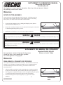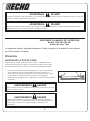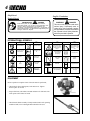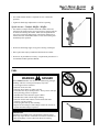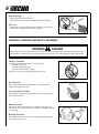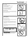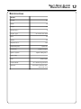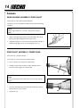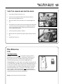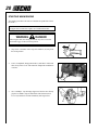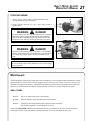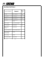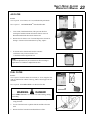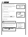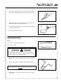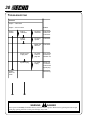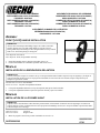
1
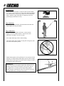
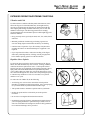
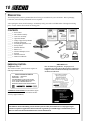
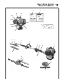
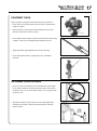
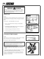
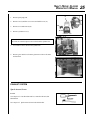
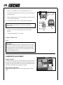
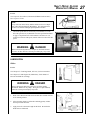
Shaft Hedge Clipper
Operator's Manual
MODEL:
HCA-261
Serial Number 002001001 - 02999999
WARNING
DANGER
Read rules for safe operation and instructions carefully. ECHO provides an Operator's
Manual and a Safety Manual. Both must be read and understood for proper and safe operation. Failure to do so could result in serous injury.
X7502094700
X750001220
06/00
SUPPLEMENT TO OPERATOR'S MANUAL
Model HCA-260, HCA-261
Serial Number: All
This Supplement contains important information. Please keep with your Operator’s Manual.
The following section has been added:
OPERATION
ROTATE CUTTER ASSEMBLY
Always use the unit from the right-hand side of your body – NEVER from the left
side. Rotate cutter assembly 180 degrees on driveshaft in order to avoid cutting
directly above your head, and to avoid contact with hot muffler.
1.
Loosen gearcase clamping screw (A), hand guard clamping screw (B), and
remove gearcase locating screw (C).
B
2.
Rotate cutter assembly 180-degrees on driveshaft until locating hole in driveshaft
is visible through locating hole in gearcase.
3.
Install gearcase locating screw (C), and securely tighten all hardware.
WARNING
A
C
DANGER
Hedge Clipper blades are very sharp. Wear gloves to protect hands when rotating cutter assembly or serious personal injury may
result.
WARNING
DANGER
During operation, the complete unit, especially the drive shaft housing and gearcase may become too hot to touch. Avoid contact
when rotating cutter assembly.
SUPLEMENTO DEL MANUAL DEL OPERADOR
Modelo HCA-260, HCA-261
Número de serie: Todas
Este suplemento contiene la información importante.
Guarde por favor con el manual de su operador.
La sección siguiente se ha agregado:
OPERACIÓN
PARA GIRAR EL CONJUNTO DE CORTADOR
Use siempre la unidad del lado derecho de su cuerpo - NO USE NUNCA la del lado
izquierdo. Gire 180 grados el conjunto de cortador en el eje de impulsión para no
cortar directamente por encima de la cabeza, y para no hacer contacto con el
silenciador caliente.
1.
2.
3.
Afloje el tornillo de sujeción de la caja de engranajes(A), el tornillo de sujeción
del protector de la mano (B) y quite el tornillo guía de la caja de engranajes (C).
Gire 180 grados el conjunto de cortador en el eje de impulsión hasta que se pueda
ver el agujero de guía por el agujero de guía de la caja de engranajes.
Instale el tornillo guía de la caja de engranajes (C) y apriete bien toda la
tornillería.
1
SUP22203863
B
A
99922203863
08/05
C
ADVERTENCIA
PELIGRO
Las hojas del cortasetos están muy afiladas. Lleve guantes para protegerse las manos al girar el conjunto de cortador, ya que de lo
contrario se pueden producir lesiones personales.
ADVERTENCIA
PELIGRO
Durante la operación, la unidad completa, especialmente la caja del eje de impulsión y la caja de engranajes pueden calentarse
demasiado al tacto. Evite el contacto al girar el conjunto de cortador:
SUPPLÉMENT AU MANUEL DE L’OPÉRATEUR
Modèle: HCA-260, HCA-261
Numéro de série: Tous
Ce supplément contient l’information importante. Veuillez le garder avec le manuel de votre opérateur.
La section suivante a été ajouté:
UTILISATION
ROTATION DE LA TÊTE DE COUPE
Toujours utiliser l’outil en le tenant à la droite du corps – JAMAIS à la gauche.
Tourner la tête de coupe de 180 degrés sur l’arbre moteur, pour éviter de couper
directement au0dessus de soi et d’éviter le contact avec l’échappement brûlant.
1.
2.
3.
Desserrer la vis de fixation du carter d’engrenages (A), la vis de fixation de la
garde de main (B) et retirer la vis de guidage du carter d’engrenages (C).
Tourner la tête de coupe de 180 degrés sur l’arbre moteur, de façon à ce que le
trou de l’arbre soit visible au travers de celui du carter d’engrenages.
Installer la vis de guidage du carter d’engrenages(C) et serrer fermement toute la
boulonnerie.
AVERTISSEMENT
DANGER
Porter des gants lors de la manipulation de l’accessoire de coupe pour éviter des
risques de blessures graves.
AVERTISSEMENT
DANGER
Pendant le fonctionnement, l’ensemble de l’outil, en particulier le boîtier de
l’arbre moteur et le carter d’engrenages peuvent devenir trop chauds pour être
touchés. Éviter le contact avec ces pièces lors de la rotation du carter
d’engrenages.
2
B
A
C
SHAFT HEDGE CLIPPER
OPERATOR'S MANUAL
MANUAL SAFETY SYMBOLS AND IMPORTANT INFORMATION
Throughout this manual and on the product itself, you will find safety
alerts and helpful, information messages preceded by symbols or key
words. The following is an explanation of those symbols and key
words and what they mean to you.
IM
PO
RT
This symbol accompanied by the words WARNING
and DANGER calls attention to an act or condition that
can lead to serious personal injury to operator and
bystanders.
The circle with the slash symbol means whatever is
shown within the circle is prohibited.
AN
T
T
NO
E
IMPORTANT
The enclosed message provides
information necessary for the protection
of the unit.
NOTE
This enclosed message provides tips for
use, care and maintenance of the unit.
SAFETY
DECALS
Locate these safety decals on your unit. The complete unit illustration, found in the "DESCRIPTION" section, will help
you locate them. Make sure the decals are legible and that you understand and follow the instructions on them. If a decal
cannot be read, a new one can be ordered from your ECHO dealer. See PARTS ORDERING instructions for specific
information.
WARNING
DANGER
This unit is not designed to insulate against hazards associated with the contact of wires
carrying electrical current.
To avoid possible injury/death due to electrical shock or other hazards. DO NOT operate unit if
any wires (power, telephone, cable, etc.) are closer than 15 feet (4/5 meters minimum distance,
to any part of the unit or operator.
WARNING
P/N 89016012360
DANGER
This unit can be dangerous if used improperly. • Falling objects and/or blade
contact can cause serious injury to operator, helpers and bystanders. • Keep helpers
and bystanders at least 50 feet (15m) clear of operating area. • To reduce injury risk,
READ AND UNDERSTAND the operator's Manual, replacement copies are available
through your ECHO dealer. • Wear Protective clothing (head, hearing and eye
protection meeting ANSI standards) specified in the Operator's Manual. • STOP
engine before making repairs or blade adjustments. • ALWAYS use adjustment handle
when adjusting blade angle. • Keep hand away from blade.
3
4
Shaft Decal
Spanish Decal
English Translation
ADVERTENCIA
89022809560
PELIGRO
Esta unidad puede ser peligrosa y producir lesiones
personales graves si no se usa en forma adecuada. Para
reducir el riesgo de lesionarse, los operadores, los
ayudantes y los espectadores deben leer y comprender el
Manual Del Operador y los Manuales De Seguridad que se
entregan escritos en español.
WARNING
DANGER
This unit can be dangerous and cause
serious injury if improperly used. to
reduce injury risk to operator, helpers
and bystanders, read and understand
the Operator's and Safety Manuals,
which are provided in Spanish.
INTERNATIONAL SYMBOLS
Symbol form/shape
Symbol
description/application
Symbol form/shape
Symbol
description/application
Read and understand
Operator's Manual.
Fuel and oil mixture
Wear eyes, ears and
head protection
Finger Severing Hazard
Wear slip resistant
foot wear.
Wear hand
protection. Use
two handed.
Hot
Surface
Safety/Alert
Symbol form/shape
Symbol
description/application
Avoid all power lines.
This unit is not insulated against electrical
current.
Keep bystanders at
least 15 meters
(50 feet) away.
Engine choke
control.
DO NOT smoke
near fuel.
Primer bulb
DO NOT allow
flames or sparks
near fuel.
Carburetor adjustment
- Low speed mixture
EQUIPMENT
Before operation a complete check of the unit must be performed;
• Check unit for loose/missing nuts, bolts and screws. Tighten
and/or replace as needed.
• Inspect fuel lines, tank and area around carburetor for fuel leaks. DO
NOT operate unit if leaks are found.
• Check that the blade assembly is firmly attached and in safe operating
condition. Dull, loose or damaged blades should not be used.
Symbol form/shape
Symbol
description/application
Do not operate closer
than 15 M (50 ft.) from
electrical
hazards.
Emergency stop
Ignition
ON/OFF
Carburetor adjustment
- High speed mixture
Carburetor adjustment
- Idle speed
SHAFT HEDGE CLIPPER
OPERATOR'S MANUAL
• Check that shoulder harness is adjusted for safe, comfortable
operation.
• Tighten the blade angle adjustment lever before operating.
Spark Arrestor - Catalytic Muffler / Muffler
• The muffler or catalytic muffler controls the exhaust noise and
emissions. The spark arrestor screen prevents hot, glowing particles
of carbon from leaving the muffler. Make sure the spark arrestor
screen is in good repair and properly seated in the muffler. Keep
exhaust area clear of flammable debris. Avoid contact during and
immediately after operation.
• Do not use shaft hedge clipper if any part is missing or damaged.
• Have repairs done only by an authorized ECHO Service Dealer.
• Do not use any attachment, accessory or replacement part unless it is
recommended in this Operator's Manual.
FUEL
WARNING
DANGER
Fuel is VERY flammable. Use extreme care when mixing, storing or
handling, otherwise serious personal injury may result.
• Use an approved fuel container.
• DO NOT smoke near fuel.
• DO NOT allow flames or sparks near fuel.
• Fuel tanks/cans may be under pressure. Always loosen fuel caps
slowly allowing pressure to equalize.
• NEVER refuel a unit when the engine is HOT!
• NEVER refuel a unit with the engine running.
• DO NOT fill fuel tanks indoors. ALWAYS fill fuel tanks
outdoors over bare ground.
• Securely tighten fuel cap after refueling.
• Inspect for fuel leakage. If fuel leakage is found, do not start or
operate unit until leakage is repaired.
IMPORTANT
Spilled fuel is a leading cause of hydrocarbon emissions. Some
states may require the use of automatic fuel shut-off containers to
reduce fuel spillage. Contact your ECHO dealer for ordering
information.
5
6
After Refueling;
• Wipe any spilled fuel from the unit.
• Move at least 3 M (10 ft.) from refueling location before starting.
After Use;
• DO NOT store a unit with fuel in its tank. Leaks can occur. Return
unused fuel to an approved fuel storage container.
3 M (10 ft.)
PERSONAL CONDITION AND SAFETY EQUIPMENT
WARNING
DANGER
Hedge Clipper users risk injury to themselves and others if the shaft hedge clipper is used improperly and or safety
precautions are not followed. Proper clothing and safety gear must be worn when operating a shaft hedge clipper.
Physical Condition
Your judgment and physical dexterity may not be good:
• if you are tired or sick,
• if you are taking medication,
• if you have taken alcohol or drugs.
Operate unit only if you are physically and mentally well.
Eye Protection
Wear eye protection that meets ANSI Z87.1 or CE requirements
whenever you operate the unit.
Face and Head Protection
When trimming overhead, wear head protection meeting ANSI Z89.1
with a full face shield.
Hand Protection
Wear no-slip, heavy duty work gloves to improve your grip on the
unit handles. Gloves also reduce the transmission of machine vibration
to your hands.
Hearing Protection
Wear hearing protection. ECHO recommends wearing hearing protection whenever unit is used.
SHAFT HEDGE CLIPPER
OPERATOR'S MANUAL
Proper Clothing
Wear snug fitting, durable clothing;
• Pants should have long legs, shirts with long sleeves.
• DO NOT WEAR SHORTS,
• DO NOT WEAR TIES, SCARVES, JEWELRY.
Wear sturdy work shoes with non-skid soles;
• DO NOT WEAR OPEN TOED SHOES,
• DO NOT OPERATE UNIT BAREFOOTED.
Hot Humid Weather
Heavy protective clothing can increase operator fatigue which may lead
to heat stroke. Schedule heavy work for early morning or late afternoon
hours when temperatures are cooler.
SAFE OPERATION
Determine Operation Area
• Provide all operators of this equipment with the Operator's Manuals
and instructions for safe operation.
• Review the area to be trimmed. Look for hazards that could contribute
to unsafe conditions. DO NOT operate unit if any wires (power,
telephone, cable, etc.) are closer than 4.5 M (15 ft.) to any part of the
operator or unit.
• Spectators and fellow workers must be warned, and children and
animals prevented from coming nearer than 15 M (50 ft.) while the
Hedge Clipper is in use.
Operation
WARNING
DANGER
Do not operate this product indoors or in inadequately ventilated
areas. Engine exhaust contains poisonous emissions and can cause
serious injury or death.
Use Proper Clothing & Equipment
• Before starting the unit, equip yourself and any other person
working within the 15 M (50 ft.) Safety Zone with the required
Protective Equipment and clothing.
7
8
Avoid Hot Surfaces
• During operation, the muffler or catalytic muffler and surrounding
cover may become extremely hot. Avoid contact during and immediately after operation. Always keep exhaust area clear of flammable
debris. Allow the engine and muffler to completely cool before
performing any maintenance activity.
Keep A Firm Grip
• Hold the front and rear handles with both hands with thumbs and
fingers tightly encircling the handles
Keep A Solid Stance
• Maintain footing and balance at all times. Do not stand on
slippery, uneven or unstable surfaces. Do not work in odd
positions or on ladders. Do not over reach.
• Never adjust blade angle of HCA while standing.
• Only adjust cutting angle with HCA resting flat on the ground, with
the switch in the "STOP" position.
• Adjust cutting angle by moving locking lever (A) up. Depress blade
indexing lever (B) and change blade angle with rear cutter assembly
handle. Release indexing lever into notch. Move locking lever down
to completely engage internal gears.
IMPORTANT
Lever (A) does not secure gearbox angle setting. Moving lever in
the down position reduces internal play in the gear box. Do not
over tighten nut (C) to insure gear box angle setting tightness
because damage to internal gears will occur. If the lever is loose or
very tight adjust nut (C) for snug 90° movement.
A
B
C
SHAFT HEDGE CLIPPER
OPERATOR'S MANUAL
EXTENDED OPERATION/EXTREME CONDITIONS
Vibration and Cold
It is believed that a condition called Raynaud’s Phenomenon, which
affects the fingers of certain individuals may be brought about by
exposure to vibration and cold. Exposure to vibration and cold may
cause tingling and burning sensations followed by loss of color and
numbness in the fingers. The following precautions are strongly
recommended because the minimum exposure which might trigger the
ailment is unknown.
• Keep your body warm, especially the head, neck, feet, ankles, hands
and wrists.
• Maintain good blood circulation by performing vigorous arm
exercises during frequent work breaks and also by not smoking.
• Limit the hours of operation. Try to fill each day with jobs where
operating the trimmer or other hand-held power equipment is not
required.
• If you experience discomfort, redness and swelling of the fingers
followed by whitening and loss of feeling, consult your physician
before further exposing yourself to cold and vibration.
Repetitive Stress Injuries
It is believed that overusing the muscles and tendons of the fingers,
hands, arms and shoulders may cause soreness, swelling, numbness,
weakness and extreme pain in those areas. Certain repetitive hand
activities may put you at a high risk for developing a Repetitive Stress
Injury (RSI). An extreme RSI condition is Carpal Tunnel Syndrome
(CTS), which could occur when your wrist swells and squeezes a vital
nerve that runs through the area. Some believe that prolonged exposure
to vibration may contribute to CTS. CTS can cause severe pain for
months or even years.
To reduce the risk of RSI/CTS, do the following:
• Avoid using your wrist in a bent, extended or twisted position.
Instead try to maintain a straight wrist position. Also, when grasping,
use your whole hand, not just the thumb and index finger.
• Take periodic breaks to minimize repetition and rest your hands.
• Reduce the speed and force with which you do the repetitive
movement.
• Do exercises to strengthen the hand and arm muscles.
• Immediately stop using all power equipment and consult a doctor if
you feel tingling, numbness or pain in the fingers, hands, wrists or
arms. The sooner RSI/CTS is diagnosed, the more likely permanent
nerve and muscle damage can be prevented.
9
10
DESCRIPTION
The ECHO product you have purchased has been factory pre-assembled for your convenience. Due to packaging
restrictions, some assembly of Model HCA-261 is required.
After opening the carton, check for damage. Immediately notify your retailer or ECHO Dealer of damaged or missing
parts. Use the contents list to check for missing parts.
CONTENTS
_____
_____
_____
_____
_____
_____
_____
_____
_____
_____
_____
_____
_____
_____
1 - Power Head
1 - Drive Shaft Assembly
1 - Gear Case Assembly
1 - Operators Manual
1 - Hedge Clipper Safety Manual
1 - Warranty Statement
1 - Warranty Registration Card
1 - Safety Glasses
1 - Shoulder Harness
1 - Blade Cover
1 - 2-Stroke Oil Sample, 2.6 oz.
1 - Scrench
1 - 4 mm Hex Wrench
1 - 8 mm/10 mm Wrench
EMISSION CONTROL
California Tier 2
The emission control system for these engines are
EM (Engine Modification).
AIR INDEX TAG
The Air Index Tag indicates, for purposes of
consumer awareness, how this product's emissions
compare to the standards enacted by the California
Air Resources Board.
IMPORTANT ENGINE INFORMATION
ENGINE FAMILY: YEHXS.0254CA
DISPLACEMENT: 25.4 CC
THIS ENGINE MEETS U.S. EPA PH1 AND 2000 AND
LATER CALIFORNIA EMISSION REGULATIONS FOR
S.O.R.E. REFER TO OWNER'S MANUAL FOR
MAINTENANCE SPECIFICATIONS AND ADJUSTMENTS.
An Emission Control Label is located on the engine.
(This is an EXAMPLE ONLY, information on label
varies by engine FAMILY).
PRODUCT EMISSION DURABILITY
The 300 hour emission durability period is the time span selected by the manufacturer certifying the engine
emissions output meets applicable California emissions regulations, provided that approved maintenance procedures are followed as listed in the Maintenance Section of this manual.
SHAFT HEDGE CLIPPER
OPERATOR'S MANUAL
2
1
25
11
17
24
23
18
3
22
21
19
20
13
12
9
8
7
4
6
5
14
15
11
10
16
12
1.
2.
3.
4.
5.
6.
7.
8.
9.
10.
11.
12.
13.
14.
15.
16.
17.
18.
19.
20.
21.
22.
23.
24.
25.
OPERATORS MANUAL - Read and understand this manual before operation. Keep manual in a safe location for
future reference, i.e., operation, maintenance, storage and specifications.
SAFETY MANUAL - Read and understand this manual before operation. Keep manual in a safe location as a
reference for safe operating techniques.
HEDGE CLIPPER SAFETY VIDEO - P/N 99922202800 (Not included with unit and English version only) is available
for your review and purchase at a cost of $5.00 from ECHO, INC. or any authorized ECHO dealer. The video overviews safety precautions and proper operating techniques provided in detail in the Safety Manual, and is supplemental to the Safety Manual. Read and understand the Safety Manual for complete information on safe operation.
POWER HEAD - Factory Assembled. Includes the Engine, Clutch, Fuel System, Ignition System and Starter.
GRIP, RIGHT HAND, REAR - Cushioned grip for Right Hand.
IDLE START INTERLOCK - This lever must be held during starting and idle operation when throttle trigger is
disengaged, otherwise engine will stop. The engine does not stop when trigger interlock lever is released and
throttle trigger is engaged during throttle operation. Operation of the throttle trigger is prevented unless interlock
lever is engaged.
"STOP SWITCH" mounted on top of the Throttle Trigger Housing. Move switch FORWARD to RUN, BACK to
STOP.
FRONT LEFT HAND LOOP HANDLE - Adjustable, rubber grip loop handle for proper cutting attitude and operator
comfort.
DRIVE SHAFT ASSEMBLY - Contains the Flexible Drive Cable.
BLADE ANGLE INDEXING LEVER - Spring loaded lever that engages with a notch every 15 degrees, from the
straight (in line with drive shaft) position to right angle with the drive shaft.
BLADE ANGLE LOCKING LEVER -The lever does not secure gear box angle setting. This lever MUST be placed
in the engaged (tight) position to remove internal gear play before operating the hedge clipper.
GEAR HOUSING ASSEMBLY - Gear housing assembly cutting angle is adjustable through a 90° arc.
BLADES - Double reciprocating blades mounted to a blade support bar. Double sided blades, are capable of cutting
on either side of the blade.
BLADE COVER - Used to cover blade during transport and storage. Remove blade cover before using unit.
THROTTLE TRIGGER - Spring loaded to return to idle when released. During acceleration, depress gradually for
best operating technique.
SHOULDER HARNESS - An adjustable strap that suspends the unit from the operator.
ARM REST - Provides arm rest during operation and protects arm from the hot engine.
SPARK ARRESTOR - CATALYTIC MUFFLER / MUFFLER -The muffler or catalytic muffler controls exhaust noise
and emission. The spark arrestor screen prevents hot, glowing particles of carbon from leaving the muffler. Keep
exhaust area clear of flammable debris.
FUEL TANK - Contains fuel and fuel filter.
RECOIL STARTER HANDLE - Pull handle slowly until starter engages, then quickly and firmly. DO NOT pull rope
all the way out or allow the handle to snap back, damage to the starter will occur.
FUEL TANK CAP - Covers and seals fuel tank opening.
PRIMER BULB - Pumping primer bulb before starting engine draws fresh fuel from the fuel tank priming the carburetor for starting. Pump primer bulb until fuel is visible and flows freely in the clear fuel tank return line. Pump bulb an
additional 4 or 5 times.
AIR CLEANER - Contains replaceable filter element.
CHOKE CONTROL - The choke control lever is located on the top of air cleaner housing. Move the lever to "COLD
START" to close choke for cold starting. Move lever to "RUN" to open choke.
SPARK PLUG - Provides spark to ignite fuel mixture.
SHAFT HEDGE CLIPPER
OPERATOR'S MANUAL
SPECIFICATIONS
MOD E L
L e ng th
20
W id th
25
He ig ht
25
W e ig ht (d ry) *
E ng ine Typ e
6
A ir c o o le d , two -stro k
B o re
34
S tro ke
28
D isp la ce m e nt
E xha ust S yste m
C a rb ure to r
Ig nitio n S yste m
2 5 .4
S p a rk A rr
Wa lb ro D ia p hra
F lywhe e l M a g ne to , C
S p a rk P lug
F ue l
F ue l/O il Ra tio
G a so line
M ixe d (G a s
5 0 :1 E C HO Hig h P e rfo rm
8 9 O cta ne unle a d e d . D O
m o re tha n 1 0 %
13
14
ASSEMBLY
GEAR HOUSING ASSEMBLY
/ DRIVE SHAFT
Tools Required: 8mm x 10mm Open End Wrench
Parts Required: Power Head/Drive Shaft Assembly and Gear Housing
Assembly.
NOTE
Hedge Clipper Blades are very sharp. Wear gloves to protect
hands.
1.
Slide the Gear Housing Assembly on the Drive Shaft. Be certain
the Flex Drive Shaft engages the hole in Driver Gear.
2.
Align the locating screw (A) with the locating hole (B) in the Drive
Shaft Housing, tighten screw (A) and clamping screws (C).
DRIVE SHAFT ASSEMBLY / POWER HEAD
Tools Required: 4 mm Hex Wrench
Parts Required: Power Head, Drive Shaft Assembly
1.
Loosen, the bolt (A) at engine drive shaft clamp.
2.
Carefully fit drive shaft assembly to engine making sure that
inner drive shaft engages into clutch mount.
A
NOTE
Lower gear housing cutter head assembly must be in line with the
engine.
3.
Turn drive shaft housing so that center line of housing is midway
between the two arrows on shaft.
4.
Tighten bolt (A).
A
SHAFT HEDGE CLIPPER
OPERATOR'S MANUAL
THROTTLE LINKAGE AND IGNITION LEADS
1.
Close choke and remove air filter cover.
2.
Loosen nut (A) and place threaded end of throttle linkage in
bracket slot. Finger tighten nut (A).
3.
Place inner cable in slot of carburetor swivel (B) and tighten nut
(A).
4.
Check throttle for freedom of movement and that wide open throttle
/ low idle extremes are adjusted properly. If adjustment cannot be
achieved with adjusting nuts, consult with your Echo Dealer for
correct adjustment procedure.
5.
Connect ignition stop leads (C) and (D).
6.
Bundle and secure ignition leads against engine housing with clip
(E).
7.
Install air filter and cover.
C
B
A
D
E
PRE-OPERATION
FUEL
Fuel Requirements
Gasoline - Use 89 Octane [R +2 M ] (mid grade or higher) gasoline or
gasohol known to be good quality. Gasohol may contain up to 10%
Ethyl (grain) alcohol or 15% MTBE (methyl tertiary-butyl ether).
Gasohol containing methyl (wood) alcohol is NOT approved.
Two Stroke Oil - A two-stroke engine oil meeting ISO-L-EGD (ISO/CD
13738) and JASO FC standards, must be used. Echo brand Premium 50:1
oil meets these standards. Engine problems due to inadequate lubrication caused by failure to use an ISO-L-EGD and JASO FC certified oil,
such as Echo Premium 50:1 Two-stroke Oil, will void the two-stroke
engine warranty. (Emission related parts only are covered for two
years, regardless of two-stroke oil used, per the statement listed in the
California Emission Defect Warranty Explanation.)
Mixing - Follow directions on the oil container.
15
16
Handling Fuel
WARNING
DANGER
Fuel is VERY flammable. Use extreme care when mixing, storing or
handling, or serious personal injury may result.
• Use an approved fuel container.
• DO NOT smoke near fuel.
• DO NOT allow flames or sparks near fuel.
• Fuel tanks/cans may be under pressure. Always loosen fuel caps
slowly allowing pressure to equalize.
• NEVER refuel a unit when the engine is HOT!
• NEVER refuel a unit with the engine running.
• DO NOT fill fuel tanks indoors. ALWAYS fill fuel tanks outdoors
over bare ground.
• Securely tighten fuel cap after refueling.
• Inspect for fuel leakage. If fuel leakage is found, do not start or
operate unit until leakage is repaired.
IMPORTANT
Spilled fuel is a leading cause of hydrocarbon emissions. Some
states may require the use of automatic fuel shut-off containers to
reduce fuel spillage. Contact your ECHO dealer for ordering
information.
After refueling;
• Wipe any spilled fuel from the unit.
• Move at least 3 M (10 ft.) from refueling location before starting the
engine.
After use;
• DO NOT store a unit with fuel in its tank. Leaks can occur.
Return unused fuel to an approved fuel storage container.
Storage Fuel storage laws vary by locality. Contact your local government for
the laws affecting your area. As a precaution, store fuel in an approved,
air tight container. Store in a well ventilated, unoccupied building, away
from sparks and flames. Do not store fuel longer than 30 days.
IMPORTANT
Stored fuel ages. Do not mix more fuel than you expect to use in
thirty (30) days, ninety (90) days when a fuel stabilizer is added.
IMPORTANT
Stored two-stroke fuel may separate. ALWAYS shake fuel
container thoroughly before each use.
3 M (10 ft.)
S
1
8
15
22
29
M
2
9
16
23
30
T
3
10
17
24
31
W T
4 5
11 12
18 19
25 26
F S
6 7
13 14
20 21
27 28
SHAFT HEDGE CLIPPER
OPERATOR'S MANUAL
EQUIPMENT CHECK
Before operation a complete check of the unit must be performed;
• Check unit for loose/missing nuts, bolts and screws. Tighten and/or
replace as needed.
• Inspect fuel lines, tank and area around carburetor for fuel leaks.
DO NOT operate unit if leaks are found.
• Check that the blade assembly is firmly attached and in safe operating
condition. Dull, loose or damaged blades should not be used.
• Tighten the Blade angle adjustment lever before operating.
• Check that shoulder harness is adjusted for safe, comfortable
operation.
DETERMINE OPERATION AREA
• Review the area to be trimmed. Look for hazards that could contribute to unsafe conditions. DO NOT operate unit if any wires (power,
telephone, cable, etc.) are closer than 4.5 M (15 ft.) to any part of the
operator or unit.
• Spectators and fellow workers must be warned, and children and
animals prevented from coming nearer than15 M (50 ft.)while the
trimmer is in use.
17
18
OPERATION
WARNING
DANGER
Do not operate this product indoors or in inadequately ventilated
areas. Engine exhaust contains poisonous emissions which can
cause serious injury or death.
• Provide all operators of this equipment with the Operator's Manual
and instructions for safe operation.
• Before starting the unit, equip yourself and any other person working
within the 15 M (50 ft.) Safety Zone with the required Protective
Equipment and clothing.
• Check that shoulder harness is adjusted for safe, comfortable operation.
• During operation, the muffler or catalytic muffler and surrounding
cover may become extremely hot. Avoid contact during and immediately after operation. Always keep exhaust area clear of flammable
debris. Allow the engine and muffler to completely cool before
performing any maintenance activity.
• Never adjust blade angle while standing.
• Only adjust cutting angle with HCA resting flat on the ground, with
the switch in the "STOP" position.
• Adjust cutting angle by moving locking lever (A) up. Depress blade
indexing lever (B) and change blade angle with rear cutter assembly
handle. Release indexing lever into notch. Move locking lever down
to completely engage internal gears.
A
B
IMPORTANT
Locking lever (A) does not secure gear housing angle setting.
Moving lever in the down position reduces internal play in the gear
housing. Do not over tighten nut (C) to insure gear housing angle
setting tightness because damage to internal gears will occur. If
the lever is loose or very tight, adjust nut (C) for snug 90° movement.
C
SHAFT HEDGE CLIPPER
OPERATOR'S MANUAL
STARTING COLD ENGINE
WARNING
DANGER
The blades should not move at idle. If blades move, readjust
carburetor according to "Carburetor Adjustment" instructions in
this manual or see your ECHO Dealer, otherwise serious personal
injury may result.
A
1.
Stop Switch - Start/Run.
Move stop switch button (A) forward away from the STOP
position.
2.
Close Choke - Cold Start.
Move choke lever (B) to Cold Start Position.
D
B
3.
Primer - Pump Bulb.
Pump primer bulb (C) until fuel is visible and flows freely in the
“Clear” fuel return line. Pump bulb an addition 4 or 5 times.
C
4.
Start - Pull Rope.
Lay the hedge clipper on a flat clear area. Firmly grip the rear
handle, depress and hold the "Idle Start Interlock Lever" (D). Pull
the recoil starter handle (E) until engine fires.
NOTE
"Idle Start Interlock Lever" must be held tight against the grip or
engine will stop at idle.
5.
Open Choke - Run.
Move the choke lever to the OPEN - RUN position. Restart engine
if necessary and allow to warm up running at idle for several
minutes.
E
19
20
STARTING WARM ENGINE
The starting procedure is the same as Cold Start except DO NOT close
the choke.
NOTE
If engine does not start after 5 pulls, use Cold Start Procedure.
WARNING
DANGER
When engine starts, the cutting attachment may move even with
the throttle trigger in idle (released) position.
A
D
1.
Stop Switch - Start/Run. Move stop switch button (A) away from
the STOP position.
2.
Primer - Pump Bulb. Pump primer bulb (C) until fuel is visible and
flows freely in the “Clear” fuel return line. Pump bulb an addition 4
or 5 times.
C
3.
Start - Pull Rope. Lay the hedge clipper on a flat clear area. Firmly
grip the rear handle, depress and hold the "Idle Start Interlock
Lever" (D). Pull the recoil starter handle (E) until engine fires.
E
SHAFT HEDGE CLIPPER
OPERATOR'S MANUAL
21
STOPPING ENGINE
1. Release Throttle. Allow engine to idle down and blades stop
moving with throttle trigger disengaged.
D
2. Release "Idle Start Interlock Lever" (D) - Move "Stop Switch" to
STOP position.
WARNING
DANGER
The engine does not stop when idle start interlock lever is released
and throttle trigger is engaged. Release throttle trigger and allow
engine to idle down and blades stop moving before releasing idle
start interlock lever, otherwise serious personal injury may result.
WARNING
DANGER
If engine does not stop during step 2, close choke - COLD START
position - to stall engine. Have your ECHO dealer repair stop switch
before using hedge clipper again or serious personal injury may
result.
B
NOTE
Refer to the Hedge Clipper Safety Manual for proper and safe hedge
clipping operation.
MAINTENANCE
Your ECHO product is designed to provide many hours of trouble free service. Regular scheduled maintenance will help
achieve that goal. If you are unsure or are not equipped with the necessary tools, you may want to take your unit to an
ECHO Service Dealer for maintenance. To help you decide whether you want to DO-IT-YOURSELF or have the ECHO
Dealer do it, each maintenance task has been graded. If the task is not listed, see your ECHO Dealer for repairs.
SKILL LEVEL
Level 1 =
Easy to do. Most required tools come with unit.
Level 2 =
Moderate difficulty. Some specialized tools may be required.
Level 3 =
Experience required. Specialized tools are required. ECHO recommends
that the unit be returned to your ECHO dealer for service
ECHO offers REPOWERTM Maintenance Kits and Parts to make your maintenance job easier. Just below each task
heading are listed the various part numbers required for that task. See your ECHO dealer for these parts.
22
MAINTENACE INTERVALS
Maintenance
Procedure
Component/System
Daily or
Before
Use
Air Filter
Clean / Replace
Fuel Strainer
Clean/Replace
Fuel Line
Inspect/Replace
Carburetor
Inspect/Rebuild/
Replace
Choke System
Inspect/Clean/ Replace
I/C
Cooling System
Inspect/Clean
I/C
Muffler Spark
Arrestor
Inspect/Clean
Cylinder Exhaust Port
Inspect/Clean/Decarbon
Drive Shaft (Flex
Cable Models)
Grease
Gear Housing
Grease
Recoil Starter Rope
Inspect/Clean
I
F
I
I
lL
k
t/R
l
I/C
I
SHAFT HEDGE CLIPPER
OPERATOR'S MANUAL
AIR FILTER
Level 1.
Tools required: 25 or 50 mm (1 or 2 in.) medium bristle paint brush.
Parts required:
90030 REPOWERTM Air & Fuel Filter Kit..
1.
Close choke (Cold Start Position). This prevents dirt from
entering the carburetor throat when the air filter is removed.
Brush accumulated dirt from the air cleaner area.
2.
Remove the air cleaner cover. Clean and inspect the element for
damage. If element is fuel soaked and very dirty, replace.
3.
If element can be cleaned and reused, be certain it:
-still fits the cavity in the air cleaner cover.
-is installed with the original side out.
NOTE
Carburetor adjustment may be needed after air filter cleaning or
replacement. See Carburetor Adjustment Section.
FUEL FILTER
Level 1.
Tools required: Fuel line hook, 203-254 mm (8 - 10 in.) length of wire
with one end bent into a hook. Clean rag, funnel, and an approved fuel
container.
Parts required: 90030 REPOWERTM Air & Fuel Filter Kit.
WARNING
DANGER
Fuel is VERY flammable. Use extreme care when mixing, storing
or handling.
1.
Use a clean rag to remove loose dirt from around fuel cap and
empty fuel tank.
2.
Use the “fuel line hook” to pull the fuel line and filter from the
tank.
3.
Remove the filter from the line and install the new filter.
23
24
WARNING
DANGER
Catalytic mufflers operate at extremely high temperatures. Muffler
area must be kept clean. Do not perform maintenance on engine or
muffler until engine and muffler are completely cool, otherwise
serious personal injury may occur.
SPARK PLUG
Level 2.
Tools Required: Scrench (combination socket wrench and screw driver
supplied with unit) Feeler gauge, preferably a wire gauge. Soft Metal
Brush.
Parts Required: 90065 REPOWERTM Tune-Up Kit
1.
Remove spark plug and check for fouling, worn and rounded
center electrode.
2.
Clean the plug or replace with a new one. DO NOT sand blast to
clean. Remaining sand will damage engine.
3.
Adjust spark plug gap by bending outer electrode.
4.
Tighten spark plug to 145-155 kg/cm (125-135 in. lb.).
COOLING SYSTEMS CLEANING
Level 2.
Tools required: Cross Head Screwdriver, 4 mm Hex Wrench, Cleaning
Brush, 25 or 50 mm (1 or 2 in.) medium bristle paint brush.
Parts Required: None if you are careful.
IMPORTANT
To maintain proper engine operating temperatures, cooling air
must pass freely through the cylinder fin area. This flow of air
carries combustion heat away from the engine.
Overheating and engine seizure can occur when:
• Air intakes are blocked, preventing cooling air from reaching the
cylinder.
• Dust and grass build up on the outside of the cylinder. This build up
insulates the engine and prevents the heat from leaving.
Removal of cooling passage blockages or cleaning of cooling fins is
considered “Normal Maintenance”. Any failure attributed to lack of
maintenance is not warranted.
0.65 mm
(0.026 in.)
SHAFT HEDGE CLIPPER
OPERATOR'S MANUAL
1.
Remove spark plug lead.
2.
Remove two (2) muffler cover screws and muffler cover (A).
3.
Remove screw and arm rest (B).
4.
Remove cylinder cover (C).
C
B
A
IMPORTANT
DO NOT use a metal scraper to remove dirt from the cylinder fins.
5.
Use brush to remove dirt from the cylinder fins.
6.
Remove grass and leaves from the grid between the recoil starter
and fuel tank.
EXHAUST SYSTEM
Spark Arrester Screen
Level 2.
Tools Required: Cross Head Screwdriver, 4mm Hex Wrench, Soft
Metal Brush
Parts Required: Spark Arrestor Screen P/N 14586251030.
25
26
1.
Remove two (2) muffler cover screws and muffler cover (A).
2.
Place piston at Top Dead Center (TDC) to prevent carbon/dirt from
entering cylinder.
3.
Remove spark arrestor screen cover (B), gasket (C), gasket (D) and
screen (E) from muffler body.
4.
Clean carbon deposits from screen and muffler components.
E
NOTE
When cleaning carbon deposit, be careful not to damage the
catalylic body.
D
C
B
5.
Replace screen if it is cracked, plugged or has holes burned
through.
6.
Assemble components in reverse order.
Cylinder Exhaust Port
Level 3.
IMPORTANT
The cylinder exhaust port must be inspected and cleaned of excess
carbon every 3 months or 90 hours of operation in order to maintain
this engine within the emissions durability period. ECHO strongly
recommends that you return your unit to your ECHO dealer for this
important maintenance service.
CARBURETOR ADJUSTMENT
Engine Break-In
New engines must be operated a minimum duration of two tanks of fuel
break-in before carburetor adjustments can be made. During the breakin period your engine performance will increase and exhaust emissions
will stabilize. Idle speed can be adjusted as required.
High Altitude Adjustment
High altitude adjustment is not required for proper operation of this
engine.
A
SHAFT HEDGE CLIPPER
OPERATOR'S MANUAL
27
Level 2.
Tools required: Screwdriver, Tachometer (ECHO P/N 99051130017).
Parts required: None.
NOTE
Every unit is run at the factory and the carburetor is set in compliance with California Emission Regulations. This carburetor does
not have acceleration and high speed adjustment needles.
1.
Check idle speed and reset if necessary. If a tachometer is available, idle speed screw (A) should be set to the specifications found
on page 13 "Specifications" of this manual. Turn idle screw (A)
clockwise to increase idle speed; counter clockwise to decrease idle
speed.
WARNING
DANGER
When carburetor adjustment is completed, the blades should
not move at idle, otherwise serious personal injury may result.
LUBRICATION
Blades
Level 1.
Tools Required: Clean Rag, Brush , Oil Can, (2) 10 mm wrenches.
Parts Required: 20W Engine Oil (lubrication), 50-50 mixture of
kerosene and 20W oil (cleaning).
WARNING
DANGER
Always disconnect spark plug wire before servicing cutting
attachment. Blades are very sharp. Wear gloves to protect hands,
otherwise serious personal injury may result.
1.
Brush loose debris from blade and coat both sides of blade with the
50-50 cleaning mixture.
2.
Allow cleaning mixture to soften the remaining gummy residue
then wipe it from the blade.
3.
Apply clean oil to the entire length of the blade. Be certain the
blade bolts are lubricated.
A
28
4.
Wipe excess oil from the blade before putting the unit back in
service.
5.
Check blade tightness. Tighten blade bolts (A) until snug with 10
mm wrench. Loosen bolts 1/2 turn. Hold bolts (A) from turning and
tighten locknuts (B) with other 10 mm wrench.
Gear Housing Assembly
Level 2
Tools required: Grease Gun with Echo LubeTM 14 oz. cartridge P/N
91015 or Lithium Grease, Rag.
Parts required: Lithium Based Grease.
1.
Clean dirt from grease fittings.
2.
Carefully pump grease in each fitting. DO NOT force grease.
Too much pressure will force grease past seals and cause damage.
Apply 1-2 pumps of grease every 15-25 hours of operation.
Drive Shaft Assembly
Level 1
NOTE
Hedge Clipper drive shaft should be greased every 25 hours of
operation.
Tools required: 8MM Open End Wrench, Screwdriver, Clean Rag,
Small Brush.
Parts required: Echo LubeTM 14 oz. cartridge P/N 91015 or
Lithium Based Grease.
WARNING
DANGER
Blades are very sharp. Wear gloves to protect hands, otherwise
serious personal injury may result.
SHAFT HEDGE CLIPPER
OPERATOR'S MANUAL
1.
Loosen gear housing locating screw (A) and mounting screws (C).
Remove the gear housing assembly from the drive shaft housing.
2.
Pull the drive shaft (B) from the housing, wipe clean and re-coat
with a thin coating [1/2 oz. (15 ml)] of grease.
3.
Slide the flexible shaft back in the drive housing being careful not
to get dirt on the flex shaft.
4.
Install the gear housing assembly.
SHARPENING BLADES
Level 2.
Tools required: Flat file, Small Screwdriver
Parts required: None
WARNING
DANGER
Always disconnect spark plug wire before servicing cutting
attachment. Blades are very sharp. Wear gloves to protect hands,
otherwise serious personal injury may result.
1.
Use screwdriver to separate upper and lower cutters equal distance
apart.
2.
File each edge carefully. Follow the original shape of the blade.
IMPORTANT
If a power grinder is used DO NOT allow blade to over heat.
3.
Lubricate blades. See "Blade Lubrication Instructions", page 27
this section.
29
30
TROUBLESHOOTING
Problem
Engine -- starts hard
Engine -- does not start
Engine
Cranks
Cause
Fuel at
carburetor
No fuel at
carburetor
Fuel straine
Fuel line cl
Carburetor
Fuel at
cylinder
No fuel at
cylinder
Carburetor
Muffler wet
with fuel
Fuel Mixtur
Spark at end
of plug wire
No spark
at end of
plug wire
Stop switch
Electrical p
Interlock sw
Spark at plug
No spark
at plug
Spark gap
Covered w
Fouled with
Spark plug
Engine
does not
crank
Internal eng
WARNING
DANGER
Fuel vapors are extremely flammable and may cause fire and/or explosion. Never test for ignition spark near an open
spark plug opening, otherwise serious personal injury may result.
SHAFT HEDGE CLIPPER
OPERATOR'S MANUAL
STORAGE
WARNING
DANGER
During operation the muffler or catalytic muffler and surrounding
cover become hot. Always keep exhaust area clear of flammable
debris during transportation or when storing, otherwise serious
property damage or personal injury may result.
Long Term Storage (over 30 days)
Do not store your unit for a prolonged period of time (30 days or longer)
without performing protective storage maintenance which includes the
following:
1.
Store unit in a dry, dust free place, out of the reach of children.
WARNING
DANGER
Do not store in enclosure where fuel fumes may accumulate or
reach an open flame or spark or serious personal injury may result.
A
2.
Place the stop switch (A) in the "OFF" position.
3.
Remove accumulation of grease, oil, dirt and debris from exterior of
unit.
4.
Perform all periodic lubrication and services that are required.
5.
Tighten all the screws and nuts.
6.
Drain the fuel tank completely and pull the recoil starter handle
several times to remove fuel from the carburetor.
7.
Remove the spark plug and pour 7 cc (1/4 oz.; 1/2 tablespoon) of
fresh, clean, two-stroke engine oil into the cylinder through the
spark plug hole.
A.
B.
C.
Place a clean cloth over the spark plug hole.
Pull the recoil starter handle 2-3 times to distribute the oil
inside the engine.
Observe the piston location through the spark plug hole. Pull
the recoil handle slowly until the piston reaches the top of its
travel and leave it there.
8.
Install the spark plug (do not connect spark plug cable).
9.
Install blade cover on blades.
31
SERVICING INFORMATION
PARTS
Genuine ECHO Parts and ECHO REPOWER™ Parts and Assemblies for
your ECHO products are available only from an Authorized ECHO
Dealer. When you do need to buy parts always have the Model
Number and Serial Number of the unit with you. You can find these
numbers on the engine housing. For future reference, write them in the
space provided below.
Model No. _____________ SN. ____________
SERVICE
Service of this product during the warranty period must be performed
by an Authorized ECHO Service Dealer. For the name and address of
the Authorized ECHO Service Dealer nearest you, ask your retailer or
call: 1-800-432-ECHO (3246). When presenting your unit for Warranty
service/repairs, proof of purchase is required.
DEALER?
Call
1-800-432-ECHO
ECHO CONSUMER PRODUCT SUPPORT
If you require assistance or have questions concerning the application,
operation or maintenance of this product you may call the ECHO
Consumer Product Support Department at 1-800-673-1558 from 8:00 am
to 5:00 pm (Central Standard Time) Monday through Friday. Before
calling, please know the model and serial number of your unit to help
your Consumer Product Support Representative.
CONSUMER PRODUCT
SUPPORT
1-800-673-1558
8 - 5 Mon - Fri C.S.T.
WARRANTY CARD
This card is our means of registering all original owners of ECHO
equipment. The card plus proof of purchase provides you the assurance that authorized warranty work will be done. It also provides a
direct link between you and ECHO if we find it necessary to contact
you.
ADDITIONAL OR REPLACEMENT MANUALS
Safety Manuals P/N 89857020060 are available, free of charge, from
your ECHO dealer or by contacting Echo Incorporated, 400 Oakwood
Road, Lake Zurich, IL 60047.
Operator's and Parts Manuals are available for purchase from your
ECHO dealer or directly from ECHO. [See ordering instructions below.]
Safety Video is available from you dealer. A $5.00 shipping charge will
be required.
ORDERING INSTRUCTIONS
ECHO, Incorporated
400 Oakwood Road
Lake Zurich, IL 60047
Technical Publications Orders
To obtain a Parts Catalog or Operator's Manual send a check or money order for $2.00 per Parts Catalog or $1.50 per
Operator's Manual made payable to ECHO, INCORPORATED. State on a sheet of paper the model number and serial
number of the ECHO unit you have, part number of the manual (if known), your name and address and mail to address
above.
Available Parts Catalog
HCA-261 S/N 001001 & Up
Part Number 99922203176
ECHO, INCORPORATED
400 OAKWOOD ROAD
LAKE ZURICH, IL 60047 U.S.A.
SUPPLEMENT TO OPERATOR'S MANUAL
PART NUMBER 89861112351 (X7502248801)
FOR MODEL: HCA-2400
PART NUMBER X750000680 (X7502092700)
FOR MODEL: HCA-260
PART NUMBER X750001220 (X7502094700)
FOR MODEL: HCA-261
SUPLEMENTO DEL MANUAL DEL OPERADOR
NÚMERO DE PIEZA 89861112351 (X7502248801)
PARA LOS MODELO: HCA-2400
NÚMERO DE PIEZA X750000680 (X7502092700)
PARA LOS MODELO: HCA-260
NÚMERO DE PIEZA X750001220 (X7502094700)
PARA LOS MODELO: HCA-261
SUPPLÉMENT AU MANUEL DE L’OPÉRATEUR
RÉFÉRENCE 89862512362 (X7502247702)
POUR MODÈLE : HCA-2400
ASSEMBLY
FRONT (LOOP) HANDLE INSTALLATION
IMPORTANT
Always store and transport shaft hedge clippers in a stable, horizontal
position. Support gear case and cutting blades to prevent excessive
flexing which may cause damage to the cutting attachment. Always install
blade cover when transporting or storing unit.
Tools Required: Screwdriver
Parts Required: Front (Loop) Handle Assembly
1.
2.
Install front handle on drive shaft, do not tighten screws yet.
Position front handle for comfortable operation and secure screws.
MONTAJE
INSTALACION DE LA EMPUÑADURA DELANTERA
IMPORTANTE
Guarde y transporte siempre los cortasetos de eje en una posición horizontal estable. Soporte la caja de engranajes y las hojas de
corte para impedir una flexión excesiva que puede causar daños en el accesorio de corte. Instale siempre la tapa de la hoja al
transportar o guardar la unidad.
Herramientas necesarias: destornillador.
Piezas necesarias: conjunto de empuñadura delantera
1.
2.
Coloque la empuñadura delantera en el eje de impulsión, NO apreite aún los tornillos.
Coloque la empuñadura delantera para una operación cómoda y sujete los tornillos.
MONTAGE
INSTALLATION DE LA POIGNÉE AVANT
IMPORTANT
Toujours remiser les taille-haies à arbre dans une position stable, à l’horisontale. Soutenir le carter d’engrenages et les lames de
coupe de manière à éviter un fléchissement excessif qui pourrait endommager d’accessoire. Toujours installer le protection de lame
avant le transport ou le remisage.
Outils nécessaires :
Pièces nécessaires :
1.
Tournevis
Poignée avant
Mettre la poignée avant sur une position confortable et serrer les vis.
SUPP22203392
99922203392
07/01