1
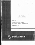
Operating Manual
H 52
8-910P
Vole 1
i gnal
2
n rat rs
and
(80 kHz -- 520 MHz)
Code NOe 52018-910P
and combination versions
in 2018-400 series
from 52018-401R
to 52018-413N
2 1
(80 kHz -- 1040 MHz)
Code NOe 52019-910E
and combination versions
in 2019-400 series
from 52019-401L
to 52019-413P
~Marconi Instruments Ltd. 1984
Printed in the UK
Part No. 46881-511A
Print code: F-10/86, MI 6.0c
Feb.85 (Am.2)
Page i
H 52018-910P
Vol. 1
CONTENTS
PRELIMINARIES
Title page
Contents
Notes and cautions
CHAPTERS
1
2
3
4
5
6
7
8
General information
Installation
Operation
Technical description
Maintenance
Replaceable parts
Servicing diagrams
Modifications and
These chapters are contained in a
separate volume available as an
op t Lona.L extra.
supp Lemen t s
HAZARD WARNING SYMBOLS
The following symbols appear on the equipment.
Symbol
Type of hazard
&.
Static sensitive device
Page (iv)
M
Component con tainin.g beryllia
Page (iv)
B9IYLUA
Reference in manual
No t e
Each page bears the date of the original issue or the code number and
date of t h e latest amendme n t (Am. 1, AM. 2 e t c , ) ,
New or amended
material of technical importance intrvduced by the latest amendment is
indicated by triangles positioned t hus ~ ••••• <lilt to show the extent of the
change.
~fuen a chapter is reissued t he triangles do not appear ..
Any changes subsequent to the latest amendment state of the manual are
included on inserted sheets coded Cl, C2 etc.
Page ii
Jun. 84
H 52018-910P
Vol. 1
NOTES AND CAUTIONS
ELECTRICAL SAFETY
PRECAUTIO~S
This equipment is protected' in accordance with lEe Safety Class 1.
It
has been designed and tested according to lEe Publication 348, 'Safety
Requirements for Electronic Measuring Apparatus', and has been supplied in a
safe condition.
The following precautions must be observed by the user to
ensure safe operation and to retain the equipment in a safe condition.
Whenever it is likely that protection has been impaired, for exalnple as a
result of damage caused by severe conditions of transport or storage, the
equipment shall be made inoperative and be secured against any unintended
operation.
Removal of covers
Removal of the covers is likely to expose live parts although reasonable
precautions have been taken in the design of the equipment to shield such
parts.
The equipment shall be disconnected from the supply before carrying
out any ad jus tnen t , rep Lacemerit or maintenance and repair during which the
equ Lpmen t 8118,.11 be opened.
If any adjustment, maintenance or repair under
voltage is inevitable it shall only be carried out by a skilled person who is
aware of the hazard involved.
Note t ha t capaci tors inside the equipment may still be charged when the
equipment has been disconnected from the supply.
Before carrying out any
work inside the equipment, capacitors connected to high voltage points should
be discharged;
to discharge mains filter capacitors, if fitted, short
together the L (live) and N (neutral) pins of the mains plug.
The mains plug shall only be inserted in a socket outlet provided with a
protective earth contact.
The protective action shall not be negated by the
use of an extension lead wi t hout; protective conductor.
Any interruption of
the protective conductor inside or outside the equipment is likely to make the
equipment dangerous.
Fuses
Note that there is a supply fuse in both the live and neutral wires of
the supply lead.
If only one of these fuses $hould rupture, certain parts of
the equipment could remain at supply potential.
To provide protection a g a in st b r e a k d own of the supply lead, its
connectors, and filter where fitted, an external supply fuse (e.g. fitted to
the connecting, plug) shouLd be used in the live lead.
The fuse should have a
continuous rating not exceeding 6 A.
Make sure that only fuses with the required rated current and of the
specified type are used for replacement.
The use of mended fuses and the
short-circuiting of fuse holders shall be avoided.
Jun. 84
Page i i i
H 52018-910P
Vol. 1
_RADIO
~REQUENCY
INTERF~~NCE
This equipment conforms with the requirements of lEe Directive 76/889 as
to limits of r.f. interference.
CAUTION:
STATIC .SENSITIVE COMPONENTS
Compone n t s identified wi.t h the symbol ~ on the circuit d.i ag r ams and/or
parts lists are static sensitive devices.
The presence of such devices
is also indicated in the equipment by orange discs, flags or labels
bearing the same sy~bol.
Certain handling precautions must be observed
to prevent these components being permanently damaged by static charges
or fast surgese
(1) If a printed board containing static sensitive components (as
indicated by a warning disc or flag) is removed, it must be temporarily
stored in a conductive plastic bag.
(2)
If a static sensitive component is to be removed or replaced the
f o Ll.owf.ng anti-static equipment must be used.
A work bench with an earthed conductive surface.
Metallic tools earthed either permanently or by repeated discharges.
A low-voltage earthed' soldering iron.
An earthed wrist strap and a conductive earthed seat cover for
operator, whose outer. clothing must not be of man.....made fibre.
the
(3) As a general precaution, avoid touching the leads of a static
sensitive component.
When handling a new one, leave i t in its
conducting mount until it is required for use.
(4)
If using a freezer aerosol in fault findings take care not to spray
p r og r ammab Le IGs as this may affect their contents.
CAUTION:
LCD HANDLIN·G·
When operating or servicing this equ1pment take care not to depress the
front or rear faces of the display module as this may damage the liquid
crystal display elements.
WARNING
HANDLING HAZARDS
This equipment Ls formed from metal pressings and although every
endeavour has been made to remove sharp points and edges care should be
taken, particularly when servicing the equipment, to avoid minor cuts.
WARNING:
TOXIC HAZARD
Many of the electronic components used in ~his equipment employ resins
.an d other chemicals which give off toxic fumes on Ln c Lne r a t Lo n ,
Appropriate precautions should therefore be taken in ·the disposal of
these Lt ems
It
Page iv
Jun. 84
H 52018-910P
Vol. 1
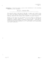
&.
Beryllia (beryllium oxide) is used in the construction of the following
components in this equipment
Unit AC4 : Transistor TRIO
...............................................................
This material, when in the form of fine dust or vapour and inhaled into
the lungs, can cause a respiratory disease.
In its solid form, as used
here, it can be handled quite safely although it is prudent to avoid
handling conditions which promote dust formation by surface abrasion.
Because of this hazard you are advised to be very careful in removing and
disposing of these components.
Do not put them in the general
industrial or domestic waste or despatch them by post.
They must. be
separately and securely packed and clearly identified to show the nature
of the hazard and then disposed of in a safe manner by an authorized
toxic waste contractor.
Jun. 84
Page v
H 52018--910P
Vol. 1
Chapter 1
GENERAL INFORMATION
CONTENTS
Para.
1
3
4
5
7
8
9
10
11
12
14
15
16
17
18
19
20
21
22
23
24
25
26
27
28
29
30
31
31
32
Features
Output
}'lodulation
Front panel
Variants 2018A/2019A
Performance data
Carrier frequency 2018A/2019A
RF output 2018A/2019A
Spurious signals 2018A/2019A
Frequency modulation 2018A/2019A
Carrier frequency
RF output
Spurious signals
Frequency modulation
Phase modulation
Amplitude modulation
Pulse modulation
AF oscillator
Frequency standard
Auxiliary inputs and outputs
Keyboard and displays
GPIB interface
Environmental
Safety
Radio frequency interference
Power requirements
Weight and dimensions
Accessories
Supplied accessories
Optional accessories
Fig.
1 80 kHz to 1040 }ffiz Mtl/FM Syn t he s Laed Signal Generator 2019A •••
Page
2
FEATURES
1.
2018A and 2019A are stable, a.m./f.m. synthesized signal generators.
2018A covers the frequency range 80 kHz to 520 MHz.
2019A includes a
frequency doubler which increases the frequency range to 1040 ~lliz.
Both are
phase locked to a frequency standard and can be set to a resolution of 10 Hz
at frequencies up to 520 MHz, and in the case of 2019A resolution of 20 Hz for
frequencies above 520 }ffiz.
Jun. 84
Chap. 1
Page 1
H 52018-910P
Vol. 1
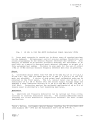
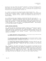
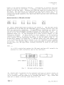
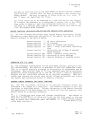
Fig. 1
80 kHz to 1040 MHz AM/FM Synthesized Signal Generator 2019A
2.
Front panel operation is carried out by direct entry of required settings
Microproce~sor control ensures maximum flexibility and
allows programming by the General Purpose Interface Bus (GPIB).*
This
facility is offered as an optional accessory enabling the instrument to be
used both as a manually operated bench mounted instrument or as part of a
fully automated test system.
Provision is also made for the use of either
111Hz or 10 MHz ex t e rnaL standard frequency reference when this is preferred.
via the ·keyboard.
3
Calibrated output levels from -127 dBm to +13 clBm (OG2 ~V to 2 V e.m.f.)
in the c.w., f sm , and cp.m. modes and up to +7 d Bm (1 V e s ms f , ) in the a s m,
mode are provided.
A choice of nine output level calibration units can be
obtained on the front panel.
The raf. output level can be set to a
r e s o Lu t Lo n of 0.1 dB or better over the' entire output voltage 'range and
features a total cumulative accuracy of ±l dB up to 520 MHz (±2 dB, 520 MHz 1040 MHz)@
Protection against the accidental application of up to 50 W of
reverse power is provided by a fast responding reed relay.
Ampli tude and frequency modulat ion can be carried out from ei t he r,
external or internal modulati.on s o u r c e s ,
The internal modulation source
provides six fixed modulation frequencies suitable for most normal
4
applications.
*GPIB . . . Marconi Lus t r ument s General Purpose Interface Bus in accordance with
IEEE Standard 488 . . . 1978 and lEe Publication 625-1 and BS 6146 Pt. 1.
H 52018-910P
Vol. 1
Front panel
5.
The instrument settings are displayed by three liquid crystal displays
that include annunciators to show the units of the displayed data.
All data
is entered on a keyboard chat; has been designed to be simple and logical to
use.
Non-volatile store and recall facilities are also provided by using an
electrically alterable read only memory store that does not require a battery
back-up system.
Carrier frequency, f s m, , <p.m., avm , , r.f., and a s f , level
functions may be incremented or decremented using the up/down keys.
6.
Second function mode of operation.
This includes the means of setting
level calibration um t s ,
access to various calibration routines, instrument running hours and an identity string that displays instrument type, software issue and serial number.
Up to 32 ASCII characters may also be stored in non-volatile memory by the
user via the GPIB bus.
Modulation input level status information is al~o
available via the GPIB bus if required.
the GPIB address, selection of alternative r s f ,
Variants
7.
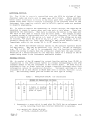
Four individual variants are available in both 2018A and 2019A.
A
s Lug Le option or a combination Lnvo LvLng up to three of the four options may
be fitted to the instrument, these are as follows:-
(1) (Extended f.m.) bandwidth, stereo and digital signalling capability.
( 2) (Avionics) providing the capability for testi-ng VOR
& 118.
( 4) (10 kHz Carrier) frequency extended range.
(8) (Pulse Mod)ulation.
Single
52018- or 52019401R
402B
403K
404A
4052
408U
409Y
410E
411U
t+12Y
413N
(1)
CombLna t Lon options
(2)
401L
402J
403F
404G
Extended f.m.
405V
Extended f
.m.
Extended f
.m.
408D
409T
410W
411D
412T
413P
s
Extended f 18m.
Extended f 8m.
Extended f.m.
(4)
(8)
Avionics
Avionics
10 kHz Carrier
IG kHz Carrier
Avionics
Avionics
10 k-Hz Carrier
10 kHz Carrier
Pulse
Pul.3e
Pulse
Pulse
Pulse
Pulse
Mod
Mod
Mod
Mod
t10d
Mod
Confirmation of the variant(s) fitted can be obtained by comparing the number
on the identification plate affixed to t h e rear of the instrument and the
above list.
Jun. 84
Chap. 1
Page 3
H 520.18.. . 910P
Vol = 1
PERFORMANCE DATA
8.
The performance specifications for2018A and 2019A are in most respects
identical, therefore t he following data applies to both instruments except
where otherwise stated.
Other variants having different parameters are
s p e cLf Le d o n Lywhe r e a more limiting parameter applies.
Where a combination
of options causes a parameter to be specified more than once then the more
limiting parameter will apply.
Alternative parameter information that is
specific. to a variant is shown in bold type.
Characteristic
Performance
2018A version
9. Range:
2019A version
80 kHz to 520 MHz (usable
80 kHz to 1040 ill1z (usable
down to 30 kHz)
down to 30 kHz) ..
It
AVIONICS VARIANTS
Range:
1.5 MHz to 520 MHz
1.5 MHz to 1040 MHz
10 kHz CARRIER VARIANTS
10.
Range:
10 kHz to 520 MHz
10 kHz to 1040 MHz
Resolution:
10 Hz up to 520 MHz
10 Hz up to 520 MHz
20 Hz f rom 520 MHz
to 1040 MHz
Level accuracy: ±1 dB
±l dB from 80 kHz to 520 MHz
±2 dB f r om 520 MHz to 1040 r-1Hz
AVIONIC VARIANTS
Level accuracy: ±2 dB from 1.5 MHz
to 5 MHz
±1 dB from 5 MHz
to 520 MHz
±2 dB from 1.5 MHz to 5 MHz
±1
±2
dB from .5 MHz to 520· MHz
dB from 520 MHz to 1040 MHz
10 kHz CARRIER VARIANTS
Level accuracy: ±1 dB from 10 kHz
to 520 MHz
Chap. 1
Page 4
±l dB from 10 kHz to 520 MHz
±2 dB from 520 .MHz to l040MHz
Jun. 84
H 52018.. . 910P
Vol. 1
Performance
Characteristic
2019A version
2018A version
PULSE MOD VARIANTS
Level accuracy:
(With pulse mod
not selected)
±l dB from 80 kHz
to 520 MHz
±l dB from 80 kHz to 520 MHz
±3 dB from 520 MHz to 1040 MHz
Level accuracy
(With pulse mod
selected and +5V
applied to input,
i.e. Carrier on)
±1.5 dB from 10 MHz
to 520 MHz
±1.5 dB from 10 MHz to 520 MHz
±4.5 dB from 520 MHz to l040MHz
Note
With pulse mod selected the maximum output
level is reduced to +3 dBm.
<1,. 2 : 1 )
VSWR:
(for output levels
below 300 mV
e.m.f.)
up to 520 l\ffiz,
<1.5:1, 520 MHz to 1040 MHz
Spurioup signals
11.
Harmonically
related signals:
for output levels
<1 V e.m.f.)
Sub..... harmonics
<.. . 30
dBc for
carrier fre~
quencies from
80 kHz to 520 MHz
None
<.. . 30
dBc for carrier frequencies
from 80 kllz to 520 MHz
<-20 dBc for carrier frequencies
from 520 MHz to 1040 MHz.
<-20 dBc for carrier frequencies
from 520 MHz to 1040 MHz.
Frequency modulation
12.
Resolution
3 digits or 10 Hz (whichever is the la~ger) up
to 520 MHz.
3 digits or 10 Hz (whichever is the larger) up to
520 MHz.
3 digits or 20 Hz (whichever is the larger) up to
1040 MHz.
Chap. 1
Jun. 84
Page 5
H 52018-910P
Vol. 1
Performance
Characteristic
13.
The remaining characteristics are common to both 2018A and 2019A.
Carrier frequency
14.
Selection:
By keyboard entry.
Frequency indication:
8 digit l.e.d. ~ for details see under
Keyboard and displays.
Accuracy:
Equal to the frequency standard
accuracy ~ see under Frequency
standard.
RF, output
15.
Level:
Selection:
0.2 u V to 2 V e s ms f , (=-127 to +13 d Bm )
in c~w. and f~m. modes.
0.2 ~V to 1 V eom.f. (~127 to +7 dBm)
when a.m. is selected.
By keyboard entry
~ units may be
mV, V, e@mof. or p.d. or
dB relative to 1 ~V, 1 mV, 1 V,
earn.f. or p.d. or dBm.
~V,
Conversion between dB and voltage units
may be achieved by pressing the
appropriate unit key (dB or V, mV, ~V).
Display~
4 digit l.c.d. with units annunciators
- see under Keyboard and displays.
Resolution:
0.1 dB or better over entire voltage
range.
Output impedance:
50
Q,
Type
N female
socket
to
MIL 39012/3D.
Reverse power protection:
An electronic trip protects the
generator output against reverse power
of up to 50 W from d.c. to 1 GHz.
The
trip may be reset from the front panel
or via the GPIB.
Spurious signals
16.
Non-harmonically related
signals:
Chap. 1
Page 6
<-70 dBc at offset frequencies greater
than 3 kHz for carrier frequencies from
2.03126 MHz to 1040 MHz.
<-60 dBc at offset frequencies greater
than 3 kHz for carrier frequencies from
80 kHz to 2.03125 MHz.
Jun. 84
H 52018....910P
Vol. 1
Characteristic
Performance
Residual f .rn , :
Less than 6 Hz rem.s. in celTT telephone
psophometric band at 520 MHz and improving
by approximately 6 dB/octave with reducing
carrier frequency down to 2.03126 -~lz.
Single side band phase noise:
Better than -130 dBc/Hz at 9011Hz and
20 kHz offset from carrier.
RF leakage:
Less than 005 ~V p.d. generated in a 50 ~
load by a 2 turn 25 rom loop, 25 rom or more
from the case of the generator with the
output level set to less than -10 dBm and
the output terminated in a 50 n sealed
load.
Frequency modulatiou_
17. Range:
(i)
Peak deviation from 0 Hz to up to 1%
of carrier frequency for carrier
frequencies f r om 2.03126 "MHz to 1040 MHz.
(ii) Peak deviation from 0 Hz to 100 kHz
for carrier frequencies up to
2.03125 MHz.
Selection:
Internal modulation oscillator or external
modulation input may be selected by the
front panel keyboard.
Display:
3 digit l.e.d. - see under keyboard and
displays.
Deviation accuracy:
±5% of deviation at 1 kHz modulating
frequency excluding residual f.m.
Frequency response:
±l dB from 50 Hz to 100 kHz relative to
1 kHz. Usable down to 10 Hz with reduced
deviation.
EXTENDED FM VARIANTS
Frequency response:
Jun. 84
±l dB from 50 Hz to 100 kHz relative to
1 kHz.
Usable down to 1 Hz with reduced deviation.
The instrument is suitable for testing
receivers requiring signalling tones with
a frequency modula.tion content down to
1 Hz.
Settling time with FM on is up to
approximately 5 seconds to be within
100 Hz of final frequency.
Chap. 1
Page 7
H 52018-910P
Vol.l
Performance
Characteristic
Stereo separation:
Better than 50 dB at 1 kHz for carrier frequencies from 88 MHz to 108 MHz.
Typical separation:
56
53
dB
50
47
20
Distortion:
30
50
80 Hz
5 kHz 15 kHz
Modulation frequency
<3% total harmonic distortion at 1 kHz modulating frequency and a deviation of up to 70% of
the maximum available at any carrier frequency.
<0.3% total harmonic distortion at 75 kHz deviation at carrier frequencies from 88 MHz to
108 MHz at 1 kHz internal modulating frequency
or external source with a.l.e. off.
External modulation:
With modulation a.l.c. on, the deviation is
calibrated for input levels between 0.8 V and
1.2 V p.d.
With modulation a.l.c. off, the
deviation is calibrated for an input level of
1 V p sd ,
HI or LO Lv e s d . . s are provided as an
aid to maintain calibrated modulation in the
a.l.c. off mode.
Input impedance is nominally
100 kn.
Phase modulation
18.
Range:
Modulation index; 0 to 10 radians for carrier
frequencies below 2.03125 MHz.
0 to a value
in radians equal to the carrier frequency in
MHz for carrier frequencies above 2.03125 MHz
subject to a maximum available phase modulation
index of 999 radians.
Selection:
Internal modulation oscillator or external
modulation may be selected by the front panel
keyboard.
Display:
3 digit l.c.d - see under keyboard and display.
Frequency response:
50 Hz to 10 kHz ±1 dB w.r.t. to 1 kHz.
Accuracy:
±5% excluding residual phase modulation.
Chap. 1
Page 8
Feb.8S (Am.2)
H 52018-910P
Vol
1
Performance
tCharacteristic
External modulRtion:
&
With modulation a.l.e. on, the -deviation is
calibrated for input levels between 0.8 V
and 1.2 V p.d. With modulation a.l.c. off,
the deviation is calibrated for an input
level of 1 V p.d.
HI or LO l.e.d's are
provided as an aid to maintain calibrated
modulation in the a.loc. off mode.
impedance is nominally 100 ~Q.
Distortion:
Input
<3% total narmonic distortion at 1 kHz
modulating frequency and at maximum
deviation (equal to the carrier frequency
in MHz) at,any carrier frequency.
Amplitude modulation
19.
Range:
o to
99% in 1% steps.
SeLec t Lou :
Internal modulation oscillator or external
modulation input may be selected.
Display:
2 digit l.e.d. - see under keyboard and
display.
Accuracy :
Better than ± (4% of depth setting +1%) for
modulation depths up to 95% and 1 kHz
modulating frequency for carrier
frequencies up to 400 MHz.
Frequency response:
±l dB from 20 Hz to 50 kHz relative to
1 kHz at 80% depth d.c. coupled.
10 kHz CARRIER VARIANTS
Frequency response:
At 10 kHz carrier frequency AM is usable
with up to 1 kHz mod. rate.
Envelope distortion:
Less than 3% total harmonic distor.tion for
modulation depths up to 80% at 1 kHz
modulating frequency for carrier
frequencies up to 400 ~ffiz.
Less than 2% total harmonic distortion for
modulation depths up to 90% at 1 kHz
modulating frequency for carrier
frequencies up to 32 MHz.
AVIONICS VARIANTS
ILS perfor·mance:
~O.045% a.m. difference in depth of
modulation for ILS tones at 90 Hz and
150 Hz each at 40% modulation depth.
Chap. 1
Jun. 84
Page 9
H 52018-910P
Vol. 1
Performance
Characteristic
External modulati.on input:
With the modulation a.l.c. on, the
modulation depth is calibrated for input
levels between 0.8 V and 1.2 V p.d.
With the modulation a.l.c. off, the
modulation depth is calibrated for an
input level of 1 V p.d.
HI or La l.e.d's
are provided as an aid to maintain
calibrated modulation in the a.l.c. off
mode.
Input impedance is nominally
100 "kS1, d. c. coupled.
PULSE MOD VARIANTS
Pulse modulation
20.
Carrier pulse response:
Rise time (lOa ns
Fall time <100 ns
Carrier on/off ratio:
>65 dB at 70 MHz carrier frequency,
reducing to
>50 dB at 520 MHz carrier frequency and
then to
>35 dB at 800 MHz carrier frequency
(usable to 1040
Propagation delay pulse
input to carrier pulse:
Typically 280 ns
Input:
Rear panel BNC connector
Input impedance 50 g
Nominal signal levels 0 V for carrier off,
+5 V for carrier on
Selection and display:
Pulse modulation is selected by pressing
AM
~M
the two keys [PULSE PULSE] simultaneously,
followed by the MOD ON-OFF key.
The
modulation window then displays P and EXT.
AF oscillator
21.
Frequencies:
300 Hz, 400 Hz, 500 Hz, 1 k.Hz , 3 k-Hz and
6 kHz selected sequentially by repetitive
pressing of the AF OSC key.
Display:
Six l.e.d's indicate selected frequency.
Frequency accuracy:
±5 %
Internal AF OSC
output:
Chap. 1
Page 10
A front panel BNC socket provides an
output for the AF signal.
Jun. 84
H
52018-910P
Vol. 1
Performance
Characteristic
Output level selection:
0.1 mV to 5 V r.m.s., selected by keyboard
entry.
Output may be entered in mV, V or
as dBm into 600 Q.
Conversion between dB
and voltage units may be achieved by
pressing the appropriate key (dB,mV,V).
The output frequency is always that of the
AF OSC and is short circuit proof. At
switch-on the AF level is set to 1 v.
Output level accuracy:
±5% above SO mV r.m.s.
±10% from 0.5 mV to 50 mV r.m.s.
Maxilnum
au t pu t
:
Distortion
Capable of driving a 2 kQ load for output
levels up to 5 V r.m.s.
Capable of driving a 600 n load for output
levels up to 2 V r.m.s.
Less than 0.1% total harmonic distortion
for a 1 kHz output frequency at an audio
level of 5 V r.m.s. into 100 kQ.
Source impedance
<10 n
Frequency standard
Internal or external frequency standard
may be selected from the front panel.
Either 1 MHz or 10 MHz standard may be
selected by second function control.
Annunciators show which is selected.
22ft
Frequency standard Input/
Output:
Internal standard:
Temperature stability:
A rear panel BNC socket provides an output
from the internal frequency standard at
either 1 or 10 MHz when internal standard
is selected.
This socket becomea the
external standard input when external
standard is selected.
High stability, oven controlled 10 MHz
crystal oscillator.
<±O.I p.p.m. over temperature range of
o to 40°C.
War'm-up time:
Jun. 84
Within 0.5 p.p.m. of final frequency
within 5 minutes from switch on at an
ambient temperature of 200C.
Chap. 1
Page 11
H 52018-910P
Vol. 1
Performance
Characteristic
Internal standard output:
Either 1 or 10 MHz, nominally 3 V p-p
square wave may be selected by second
function control.
Source impedance 100·n
nominal.
External standard input:
Accepts 1 MHz or 10 MHz of at least 1 V
r.m.s.
Maximum recommended input level,
2.5 V r.m.s.
Input impedance is
nominally 100 n.
Auxiliary inputs and outputs
23.
Modulation input:
A front panel BNC socket accepts an
external modulation input.
The input
signal may be levelled by selecting the
MOD ALe ON/OFF key.
Two l.e.d.
indicators, HI and LO provide an aid to
maLn t aLn calibrated modulation in the
a.l.c. off mode.
External modulation lnput
ALC ON;
Input level nominally 1 V r.m.s.
into 100 kn .... see under Frequency
modulation and Amplitu"de modulation.
ALe OFF; 1 V r.m.s. is required for calibrated conditions.
When the HI
and LO l.e.d's are extinguished
the input voltage will be within
the range 1 V ±5%.
Auxiliary FM input:
Deviation
The auxiliary FM input can be used to add
sub-audio tones to the main modulation
set.
The input is enabled whenever FM or
~M is selected and is independent of
whether the instrument is set to internal
or external modulation.
With the
application
INPUT will
10% of that
display.
FM on (INT or EXT) the
of 1 V r.m.s. to the AUX FM
result in an f.m. deviation of
indicated in the modulation
With ~.m. selected (INT or EXT) the
application of 1 V ·r.m.s. will result in
an f.m. deviation in kHz equal to the
phase deviation in radians shown in the
modulation display.
Accuracy
±15%.
Impedance
600 n.
This facil~ty is intended to allow the
insertion of signalling tones used in
receiver testing.
Chap. 1
Page 12
Jun. 84
H. 52018-910P
Vol. 1
Performance
Characteristic
Frequency standard
input/output:
A rear panel BNC socket provides an output
from the internal frequency standard when
internal standard is selected and becomes
the external standard input when ext e rna L
standard is selected. The choice of 1 MHz
or 10 MHz reference standard [nay be made
by a second function control.
Internal standard output:
1 MHz or 10 MHz at nominally 3 V p-p
square wave.
Source impedance 100 ~
nominal.
External standard input:
Accepts either a 1 MHz or 10 MHz signal of
at least 1 V r smvs ,
Maximum recommended
input level 2.5 V r.m.s.
Frequency
selected by second function control.
Input impedance 100 ~ nominal.
Al t e rna t Lve RF and
Blanked holes are provided so that the RF
output and modulation input socket can be
fitted to the rear panel for systems use
etc.
modulation sockets
Keyboard and displays.
24.
Main and secondary
keyboard functions:
Displays:
These are described in Chap. 3, Operation.
All instrument settings are controlled by
the front panel keyboard.
The main function of the three liquid
crystal displays is to provide a simultaneous readout of carrier frequency, modulation and r.f. level.
(i)
Carrier frequency di?play - 8 digit
with annunciators to show frequency
units, e x t e rnal f r e quency standard,
frequency limit exceeded, remote
operation selected and instrument
addressed.
(ii)
Modulation display - 3 digit with
annunciators to show modulation
units, f.m., ¢.m., avm , , modulation
off, external modulation selected,
and modulation limit exceeded.
( iii) RF 1eve 1 dis P lay - 4 dig i t wit h
annunciators to show r.f. level
units, r s f , output off, reverse
power trip operated, and r.f. level
limit exceeded and a.f. level units.
Jun. 84
Chap. 1
Page 13
H 520I8-910P
Vol. 1
Performance
Characte r Ls t Lc
GPIB interface
A GPIB interface is available as an
optional accessory and can be easily
fitted by the user.
All functions except
the SUPPLY ON switch are remotely programmable.
In addition to allowing full GPIB
control of the instrument, the GPIB module
has an auxiliary output socket which. can
be used to control relays etc.
25.
Capabilities:
Complies with the following subsets as
in IEEE 488 -- 1978 and IEC
Publication 625-1: SRI, AHI, T6, TEO, L4,
LEO, SRI, RLl, PPO, DCI, DTG, CO, EI.
d e f Ln e d
Environmental
26.
Conditions of storage and transport
Temperature:
Humidity:
Up to
Altitude:
Up to 2500 m (pressurized freight at 27 kPa
differential i.e. 3.9 Ibf/in 2 ) .
Rated range of use
(Over which full
specification is met)
Temperature:
o
90% relative humidity.
to 550C.
Safety
27.
Radio
Complies with Publication lEe 348.
f~equency
interference
28. '
Conforms to the requirements of EEC
Directive 76/889 as to limits of r.f.
interference.
Power requirements
29.
Voltage
AC supply.
Voltage ranges (switchable)
105 V .- 120 V
210 V ..- 240 V
±10%
... 440 Hz.
Frequency:
45 Hz
Consumption:
85 VA maximum.
Chap. I
Page 14
}
Jun. 84
H 52018-910P
Vol.l
Characteristic
Weight and dimensions
30.
Height:
Width:
Depth:
Weight:
Performance
(over projections but excluding optional front panel
handles).
152 mm (6 in).
425 mm (16.7 in).
525 mm (20.7 in).
16 kg (35.2 Ib).
ACCESSORIES
Supplied accessories
31.
AC supply lead
Operating manual H 52018-910P (Vol. 1)
Front panel blanking kit
Code no.
43123-076Y
46881-511A
46883-654E
Optional accessories
32.
Service manual H 52018-910P (Vol. 2)
GPIB module
Maintenance kit, includes r.f. extender cables,
l.c.d. insertion and extraction tools etc.
Rack mounting kit
Front handle kit
GPIB manual H 54811-010P (Contains details of general
GPIB protocols)
GPIB lead assy.
GPIB IEEE/IEC connector adapter
RF connecting cable TM 4969/3; 50 Q, 1.5 m (5 ft) BNC
RF coaxial cable (N to N type)
Impedance adapter 50/75 Q
Feb.85 (Am.2.)
46881-512Z
54433-001U
54711-033E
46883-506M
46883-511R
46881-365R
43129-189U
46883-408K
43126-0128
54311-095C
54411-05lX
Chap. 1
Page 15
H 52018-910P
Vol. 1
Chapter 2
INSTALLATION
CONTENTS
Para.
1 Unpacking and repacking
3 Mounting arrangements
4 Connecting to supply
6 Safety testing
7 GPIB interface
8
9
Rack mounting
Front panel handles
Fig.
1
Voltage ranges
8~.
Page
3
UNPACKING AND REPACKING
1.
Retain the container" packing ma t e r La l, and the packing Lus truct Lon 'note
(if included) in case it is necessary to reship the instrument.
2.
If the instrument is to be returned for servicing attach a label
indicating t he service required, type or model number (o'n rear label), serial
number and your return address.
Pack the instrument in accordance with the
general instructions below or with the more detailed information in the
packing instruction note.
(1) Place supply lead in suitable plastic bag and tape i t to the
instrument rear panel.
(2) Place tl1e Lns t rumen t witllin its plastic cove r ,
(3) Ensure that the padded fitting is in place within the inner carton
and slide the instrument in, rear panel first) leaving the front panel
exposed at the open end.
(4) Fit the separate front panel protecting cover over the panel and
close and seal the inner carton.
(.5) Place one of the moulded plastic cushions in t he bottom of t h e outer
carton and insert the inner carton to locate in the cushion recess.
(6) Place the other plastic cushion over the other end of the inner
carton and close and seal the outer carton.
(7) Wrap the container in waterproof paper and secure with adhesive tape.
Chap. 2
Jun. 84
Page 1
H 52018--910P
Vol. 1
(8)
}~rk
the package FRAGILE to encourage careful handling.
Note •••
If the original container or materials are not available, use a
strqng double-wall carton packed with a 7 to 10 cm layer of shock
absorbing material around all sides of t h e instrument to hold it
firmly.
Protect the front panel controls with a plywood or
cardboard load spreader; if the rear panel has guard plates or other
projections a rear load spreader is also advisable.
MOUNTING
ARRANG~mNTS
3.
Excessive temperatures may affect the instrument's performance;
therefore, completely remove the plastic cover, if one is supplied over the
case, and avoid standing t.he Lns t r umen t on or close to other equ Lpme nt t.hat Ls
hot.
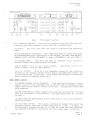
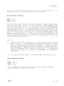
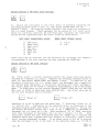
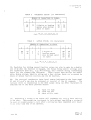
CONNECTING TO SUPPLY
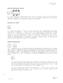
Before conne c t Lng the Lns t r ument to the a s c , supply check the position of
the two voltage selector switches on the rear panel.
A locking plate fixes
both switches into one of four possible combinations and only t he selected
voltage range is displayed when the locking plate :is fixed to the back panel.
The instrument is normally despatched with the switches selected to 230/240 V.
To select a different voltage range remove the locking plate and re-position
the switches to the required range as shown in Fig. 1 below and refit the
locking plate into its alternative position.
4.
Note
The a. c. supply fuse may also have to be changed.
An indication of the
correct fuse rating is given with each displayed voltage range:-
i.e. 1 A-T (1 amp time lag)
0.5 A-T (0.5 amp time l8.g)
105 V
120 V ±10%
210 V -- 240 V ±lO%
The fuses are 20 rom x .5 mm cartridge type.
5.
The free a.c. supply cable is fitted at one end with a female plug which
mates with t he a s c , connector at the rear of the Lns t rumen t ,
When fitting a
supply plug ensure that conductors are connected as follows:
Earth
Neutral
Live
Green/yellow
Blue
Brown
When attaching the supply lead to a non-soldered plug it is recommended that
the tinned ends of the lead are first cut off owing to the danger of cold flow
resulting in intermittent connections.
Chap. 2
Page .2
Jun.
84
H 52018-910P
Vol • .1
DO
o~
Do
o~
TPB 4495
Fig. 1
Voltage ranges (alternative switch and locking plate positions)
SAFETY TESTING
6.
Where safety tests on the a.c. supply input circuit are required, the
following procedures can be applied.
These comply with BS 4743 and lEC
Publication 348.
Tests are to be carried out as follows and in the order
given, under ambient conditions, to ensure that a.c. supply input circuit
components and wiring (including earthing) are safe.
(1) Earth lead continuity test from any part of the metal frame to the
bared end of the flexible lead for the earth pin of the user's a.c.
supply plug.
Preferably a heavy current (about 25 A) should be applied
for not more than 5 seconds.
Test limit : not greater than 0.5 Q.
(2) 500 V d.c. insulation test from the a.c. supply circuit to earth.
Test limit : not less than 2
~&.
GPIB INTERFACE
7.
The GPlB Ln t e r f a ce is an optional accessory and can eas I Ly be fitted by
the user as follows:(1) Remove and discard the rectangular cover plate from the left-hand
side of the rear panel.
(2) Withdraw the interconnecting lead from inside the instrument and
connect this to the GPIB assembly taking care that the ribbon cable
connect.o r SKAK is correctly aligned with GPIB module connector PLAK.
(3) Switch instrument on temporarily and check that the front panel
displays data correctly.
If satisfactory switch off and continue with
step (4).
If display is corrupted however then re-check the alignment
of SKAK and PLAK as indicated in step (2).
(4) Using the four retaining screws provided, secure the ·GPIB assembly to
the rear panel where four pre-positioned captive nuts are fitted.
The
interface is now ready for GPIB operation.
Jun. 84
Chap. 2
Page 3
H 52018-910P
Vol. 1
RA.CK MOUNTING
8.
The instrument may be mounted in a standard 19 inch rack using the kit
46883-S06M available as an optional accessory.
Fitting instructions are as
follows:-
(1) Remove both top and bottom outer covers, detach and discard front and
rear feet on bottom cover.
(2) Detach and discard side trim inf111s, countersunk screws and screw
cups.
(3) If it is desired to have the r.f. output and modulation input sockets
on the rear panel complete steps 4 to 10.
If rear panel connections are
not required proceed to step 11.
(4) Remove the front panel assembly by slackening the two screws exposed
in each side and lay face down protecting the l.c.d's.
(5) Disconnect the semi-rigid coaxial plug PLAV situated at the rear of
the top r.f. box and remove the four r.f. box securing screws (one in
each corner bracket); raise the box into the servicing position.
(6) Unsolder the yellow and orange wires from the front panel MOD-IN
socket and adjacent earth tag.
Unfasten and remove the socket from the
front panel mounting, remove and discard the blind grommet from the
MOD-IN alternative rear panel position.
Uncleat excessive mndulation
cableform from the lower r.f. box and re-route this to the rear panel.
Refix MOD-IN b.n.c. socket to the rear panel position.
Now reconnect
t he yellow wire to the MOD-IN socket and the orange wire to the adjacent
earth point.
Select a b.n.c. replacement blind grommet (issued with the
included blanking kit) and fit this into the front panel position.
Recleat the cable to the lower r.f. box.
(7) Disconnect the r , f. output connector from SKBA ouATO/ 1 at t enua t o r ,
and also the RF OUTPUT socke t from the front panel assembly.
Withdraw
the connector and socket through the front panel.
Similarly, remove the
blind grommet from the alternative rear panel RF OUT position, discard
this and fit the replacement 'N' type grommet (supplied in the blanking
kit) into the front panel position.
(8) Pass the r.f. output connector through the alternative rear panel
position and secure the RF OUTPUT socket to the rear panel.
Re..... route
the cable over the bottom r.f. box and reconnect SKBA to ATOll
attenuator.
(9) Lower the top r.f. box and secure this, reconnect PLAV to the rear of
the box.
Replace and secure the f r on t panel assernbly and side trim,
also refit front handles if previously fitted.
(10) Fit rack brackets in front panel handles or side trim recesses using
M4 x 16 pan head screws and washers, finally refit top and bottom covers.
Note
When fitting the unit into the rack; support at the rear should also be
given e.g. a shelf located within the rack or cubicle.
Chap. 2
Page 4
Jun. 84
H 52018-910P
Vol. 1
FRONT PANEL HANDLES
9.
Front handles are supplied only as optional a c c e s s o r I e s ,
instructions are as follows:-
fitting
(1) Remove the side trim infills and side trims.
Discard the side trt111S
but retain the side trim infills, screws and washers for re-use.
Position the instrument on its side.
(2) Fit the panel handles without the side trim infills first~ aligni3g
two i~ner screws and washers and
all four screws.
Tighten down the
remove the two outer screws.
(3) Re f tt t he side trim infills, replace tl1e outer two scr-ews and washe r s
and tighten down.
Chap. 2
Jun. 84
Page
5
B 52018-910P
Vol. 1
Chapter 3
OPERATION
CONTENTS
Para.
1 Principles of control
2
Front panel control
3
Rear panel control
4 Preparation for use
4
Switching on
5 Operating procedures
6
Setting a carrier frequency
7
Incrementing and decrementing
8
Internal modulation source
9
Setting a.f. level
10
External modulation
11
Setting f.m.
12
13
14
15
16
17
18
19
23
25
26
27
28
29
31
32
33
34
35
36
37
38
39
40
41
42
43
53
54
55
58
62
63
64
65
66
67
Setting ¢.m.
Auxiliary f.m. input socket
Setting a.m.
Setting r.f level
Setting pulse modulation
On-Off keys
Reverse power protection
Store and recall
Second function operations
Second function a 'Unlock'
Second function 1 'Status'
Second function 2 'GPIB address setting'
Second funct Lon 3 'l\fanual Lat ch settin.g'
Second function 4 'SRQ mask setting'
Second function 5 'RF level units setting'
Second function 6 'RF level offsets'
Second function 9 'Elapsed time display'
Second function 11 'Reid identity string'
Second function 12 'Write user-definable string'
Second function 13 'Read user - definable string'
Second function 14 '1 or 10 }lliz standard setting'
Second function 15 'Old /new GPIB command set'
Second function 16 'Recall STORE 10 at switch on'
Second function 18 'Set data on GPIB Aux. output pins'
Second functions 7,8,9,10,17,190,191 and 192, (Second level operation)
Operation with 75 Q loads
General purpose interface (GPIB) functions
Setting the GPIB address
GPIB programming codes
Listening function
Talking function
SFl, QU Status string
SFll, QU Identity string
SF12, User string write facility
SFl3, QU User string read facility
Service requests (SRQ)
Error numbers
continued •••
Jun;J 84
Chap. 3
Page 1
H 52018....910P
Vol • .1
CONTENTS
Parae
68
(continued)
SRQ mask
70
Reve r se power protection
Clear, switch on, and return to local
Fast output facility (GPIB only)
GPIB connector conta~t assignments
GPIB auxiliary output facility
71
72
73
74
Table
1
2
.3
Modulation string (GPIB)
Frequency string (GPIB)
Levels string (GPIB)
...
Page
22
23
23
Fig.
1
2
Front panel controls •••
3
Rear panel controls
2018A Initial operating mode ••
4
.5
13
14
16
18
2'7
3
2018A Second function '1' status mode
4
5
SRQ mask setting display
6
'Read Identity' display •
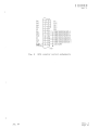
7 ' GPIB auxiliary output plug and socket connections ••
8
GPIB connector contact assignments •••
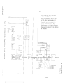
9
2018A/2019A Simplified Block Diagram •
28/29
PRINCIPLES OF CONTROL
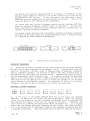
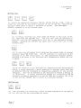
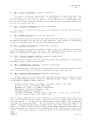
1.
Al.L operations of the ge-nerator are carried out from the front panel
keyboard which is divided into five distinct areas.
Remote operation via a
GPIB ~ontroller is possible if the optional GPIB interface is fitted.
If an
illegal operating condition is selected, either by local or remote control,
this is indicated by a limit annunciator on the front panel display~
Front panel control
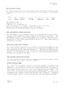
2.
(1) SUPPLY switch.
Applies the a.c. supply voltage.
(2) AF OSC, MOD ALe.
The two black keys control t he internal moduLa t Lon
frequency and the modulation automatic level contra 1.
The MOD ALe key
has an integral l.e.d. to indicate that selection has been made.
When
MOD ALe is selected a MOD input of between 0.8 automatically levelled.
1.2 V will be
(3) MOD INPUT (100 kQ) socket.
Accepts an input from an external
modulation source.
When the HI and LO l.e.d's are eKtinguished the
input voltage will be ·within the range 1 V ±5%.
(4) AU.X FM INPUT socket.
Enables t he use of additional modulation tones
e I t he r with Ln t e r n aL or exter-nal modulation source applied.
With 1 V
r.m.s~ applied the additional f.m. deviation produced is 10% of the f.m.
display va Lue ,
(5) Function keys.
The nine orauge keys each have an i-ntegral
indicate the function currently selected.
Chap. 3
Page 2
Lve s d ,
JU11
e
to
84
H 52018-910P
Volltl
MARCONI
INSTRUMENTS
80 kHz-1040 MHz
CARRIER
FREQUEN CY
MODULATION
signal generator
2019A
LEVEL
I]]
0
0
~~
FREQ
0
0
0
0
~ ~
SU PPLY
ON
MOD
INPUT
®
@-{(@)
/
'TA
HI
i.o
AUX FM
INPUT
"'\
REV PWR
RESET
LgEL
I
0
STORE
illJ
LEVEL
~~~
~
-=-J
~
~ ~
kHz
I
~
~~~
EXT
ON-OFF
O::~gFF I
ON-OFF
T0J;L
g~
I~
0
I
~
~~~
~ ~
\
\
LTPCS01S
~
Fig. 1
Front panel controls
(6) Numerical keypad.
Enters the required value for the function
currently selected, includes a minus sign and a decimal point.
(7) Units"
entry.
The four grey keys are used to terminate the numerical
(8) Miscellaneous functions.
This right-hand group of eight black keys
is concerned with such operations as AF ON/OFF, INT/EXT, MOD ON/OFF,
CARRIER ON/OFF, RETURN, DECREMENT (+ down), INCREMENT (t up) and TOTAL ~.
(9) SECOND FUNCT.
This blue key with an integral l.e.d. is used to
provide further less commonly used facilities.
(10) RF OUTPUT: 50 n N type output socket.
level is shown on the RF LEVEL display.
Indication of the r.f.
(11) AF OUTPUT.
This .is a Low impedance output at the f r e qu e uc y
selected by the internal AF OSC control and is available when either INT
or EXT modulation is selectede
This allows the testing of transceiver
audio circuits (microphone inputs etc.).
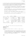
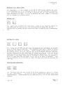
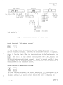
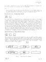
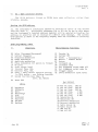
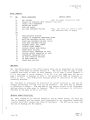
Rear panel control
3.
(1) REMOTE CONTROL GPIB INTERFACE.
This optional accessory allows
remote control of the instrument and in addition has an auxiliary output
socket which can be used to control relays etc.
Accepts the 24-way IEEE
GPIB conne c t or ,
(2) MOD INPUT/RF OUT. These blanked holes provide alternative fittings
when the Ln s t rument; is rack mounted.
Fitting instructions are included
in Chap. 2.
(3) PULSE MOD IN. This blanked hole is used only if the pulse modulator
option is fitted.
(4) STD FREQ IN-OUT.
BNC socket
possible internal reference standard
alternatively allows the use of a
The required function is selected by
Fe b. 85 (Am .. 2 )
provides an output from one of two
frequencies (1 MHz ur 10 MHz), or
1 MHz or 10 MHz external reference.
the front panel keys. If EXT STn
Chap. 3
Page 3
H 52018-9l0P
Vol.l
is selected when power is initially applied Error No.15 will be displayed in
the carrier frequency window. After a delay of approximately one minute the
external and internal frequencies will synchronize and the error numbe r will
be removed.Subseque~t changes from +NT and EXT when the instrument is at, or
near,normal operating temperature can be made/without this delay.
(5) VOLTAGE SELECTOR switches,selects in a combination of four positions
105-110 V/115-120 V, or 210-220 V/230-240 V, each has a 10% tolerance
to afford a complete cover over the voltage ranges 95 V-132 V and 190 V
-264 V respectively.
(6) Selector switch plate.
Secures the VOLTAGE SELECTOR switches into
one of four pre-selected positions by either turning and/or reversing the
plate before re-affixing to the rear panel.
(7) AC fuses.
Supply input fuses are rated at 0.5 amp (slow-blow) for
190 V-264 V r ange or 1 amp (slow-blow) for the 95 V-132 V r ange ,
(8) AC supply input.
The a.c. supply is connected through this plug
which mates with the connector fitted to the supply lead.
o
o
GPIB
9\:=3P
o
o JE'
I
PULSI~ MOO ~
AUXI LIARY
CONTROL o/>
o
I@
. RF OUT
S H 1 AH 1 TS L 1
SR 1 R L 1 E1 DC1
I
o
MOD IN
1
STO FREQ
IN-OUT
0
Fig. 2
~
C
~HZ
10
@) /)
01
//PoWER SUPPLY
105-120
or 210' 240V
50 400Hz
8 5 VA
(JJ)
~)
[j
0\
0
[i
@
0
0
@
a
@
lOMHz
TPC 45C1C
Rear panel controls with optional GPIB interface
PREPARATION FOR USE
Switching on
4.
With the instrument connected to a suitable a.c. supply proceed as
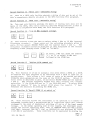
follows:(1) Switch SUPPLY ON and check that the instrument has taken up the
correct initial operating mode, that is CARRIER FREQ 520 MHz (1040 MHz
for 2019A) internal MOD OSC 1 kHz, no MODULATION and minimum RF LEVEL
(-127 dBm or equivalent).
The instrument may be set to the contents of
store 10 if second function 16 has previously been set.
For details see
the paragraph, 'Recall STORE 10 at switch on'.
Chap. 3
Page 4
Feb.85 (Am.2)
H 52018-910P
Vol. 1
(2) Before the initial operating mode is displayed an indication of the
software issue number is shown in the level window e.g. 01,02,03 for
approximately one second.
If the instrument has developed a fault
condition an error number will be continuously displayed.
Details of
these are given in the GPIB functions paragraphs.
(3) Check that the carrier frequency window does not indicate EXT STD,
unless an external frequency standard input is required.
If this has
been inadvertently selected press CARRIER FREQ and INT/EXT keys to
reselect internal frequency standard.
(4) During normal operation the instrument's internal reference standard
will give an accuracy within the rated performance after a warm-up period
of 5 minutes at normal ambient temperatures.
CARRIER
FREQUENCY
MODULATION
I
kHz
J )]
Fig. 3
.a:, ,.,
LEVEL
OFF
-f
f.Lf
dBm
2018A initial operating mode
OPERATING PROCEDURES
5.
Selection of data is carried out by first pressing the required function
Follow this with the
numerals including a decimal point or negative sign if required, a positive
sign is otherwise implied.
If an error is made in t.he entry re-selection of
the function key will clear the previous entry.
Complete the entry by pressing the appropriate UNITS terminator key.
If a request outside the operating
range of the instrument is made a LIMIT annunciator will be set on the rele....
vant display and the generator will tune to either t he minimum or the maximum
value nearest to the initial request.
One exception to this is if a carrier
frequency less than 80 kHz is selected, for details see next para.
key and this is then indicated by an integral l.e.d.
SeLting, a carrier frequency
6.
If the l.e.d. in the orange CARRIER FREQ key is off press the CARRIER
FREQ key. If the lse.d. is on this will not be necessary. Enter the required
value via the numerical key pad including the decimal point if required, the
data entered will appear in the carrier frequency display.
Terminate the
instruction by pressing the appropriate UNITS terminator key.
If a request
lower than the minimum specified frequency 80 kHz is made, the LIMIT annuciator is displayed and the instrument tunes to the requested frequency but with
a degraded performance.
When selections below 30 kHz are made the accuracy
Chap. 3
Page 5
H 52018-910P
Vol. 1
of the r s f , level output will be impaired.
Subsequent OFF/ON control is
achieved by operation of the CARRIER ON/OFF key.
Note
If the 10 kHz Carrier frequency variant is fitted the accuracy of the
selec.ted output level will be accurate down to t he lower specif ied limi t
of 10 kHz.
If the Avionics variant is fitted then the lowest specified
limit is 1.5 MHz.
w
~
7.
To display current increment values press the orange key identified by a
delta sign /1.
Initially t he instrument will automatically select and display
an increment for each of the main functions as follows:- Carrier frequency
1 kllz , Modulation, either Ft1 1 kllz , ~M 1 Rad or AJ:1 1%.
RF level 1 dB and AF
level 1 dB.
If an AF level increment is required, selecting ~, AF LEVEL,
causes the LEVEL window indication to change from the RF level increment
Ln I tially displayed to t ha t of the requested AF level Lnc rement ,
To return
the instrument to normal operation without affecting any current increment
value that may have been selected press any function key twice.
To enter a
new value of increment such as a carrier frequency step of 10 kHz, press the
keys shown in the example abo ve ,
FM, q;M, AM, ,AF or RF LEVEL may be similarly
Lnc r eme n t e d , note that if incrementing the RF LEVEL the on Ly valid te rmfnat or
is the dB 'key ..
(1) Each press of the UP key will then Lncr emerrt t he carrier frequency by
10 kHz, likewise pressing the DOWN key will decrement the carrier
frequency by a similar amount.
(2) Holding the UP or DOWN key pressed will result in continuous
incrementing or decrementing after a brief delay.
(3) Changing from the Lnc rement.Lng mode to the decr ement Lng mode wi thout
the delay can be achieved by keeping the UP key continuously pressed
allowing the instrument to increment, then following this selection press
tIle DOWN key also.
When t h e UP key is released the instrumen.t will
.immediately decrement. A reversal f r om down to up without delay can t.he n
be achieved by pressing the UP key before releasing the DOWN key, and
when the DOWN key is released the instrument will then immediately
Lncr emerrt ,
(4) To find the t o ta I shift f r orn t he original setting press the TOTAL
s h Lf t key.
While this key is pressed all the displays will show the
total shift of each function from their starting values.
To return to
the initial value of the selected function press the RETURN key.
Jun. 84
11 52018-910P
Vol
fiI
1
Internal modulation source
8.
The internal AF modulation oscillator frequency can be controlled by
successive presses of the AF ase key.
The six Ls e s d . . s adjacent to tIle AF ose
key will indicate the oscillator frequency selected.
Setting a.f. level
9.
Entry is similar to the r.f. level selection, both logarithmic and linear
scales are available.
Linear scale is always p.d. and logarithmic is dBm
into 600 Q.
Units can be converted in the same manner as the r.f. level
units.
Data is displayed in the level display, modulation and carrier
frequency are kept blank at this time.
A level of 1 V r.m.s. is set at the
Power on default mode or a different setting if . . Recall store 10 . . setting has
been set (see Second function 16 for details).
External modulation
10.
Press FM, <pM, or AM function key as appropriate followed by the INT/EXT
key to select external, this is indicated on the rnodulation display by, an EXT
annunciator.
Fur the r pre s s Lng the INT/EXT key will return the instrument to
the internal mode.
The external mod. level is monitored and HI or LO l.e.d's
are provided as an aid to maintain calibrated modulation in the a.l.e. off
mode.
(1) With MOD ALe, ON and external modulation selected the signal from the
ext e rnal l.y applied modulation source can be set Lnt e rna l.Ly t.o the correct
level (providing the applied voltage is between 0.8 V and 1.2 V).
ALe, ON selection is indicated by the integral l.e.d.
MOD
(2) With MOD ALe, OFF selected, an input of 1 V r.m.s. will produce the
displayed modulation value.
The instrument will normally power-up with
MOD ALe off when in EXT MOD mode.
JU11,
84
Chap. 3
Page 7
H
52018-910P
Vol. 1
11. Select the modulation frequency (300 Hz, 400 Hz, 500 Hz, 1 kllz , 3 kHz or
6 kHz) as required by successive presses of the AF OSC key. Continue the
selection shown above to select a deviation of 20 kllz ,
The instrument
normally switches on in the Internal mode.
(1) To select external f s m, first press t.he FM key if its Ls e s d , is not
lit, then press the INT/EXT key.
The f.m. will then be selected to
external, and the EXT annunciator will set in the modulation display
window.
Pressing the INT/EXT key again will return the f.m~ to the
internal mode.
~
~
(2) To turn f.m. off whilst still retaining the current value of entered
deviation press MOD ON/OFF key ,
The off condition is indicated by t h e
setting of an OFF annunciator in the modulation display window.
Entering a new value of f.m. deviation will automatically select the f.m.
on again.
(3) If the 2018A is to be utilized for signal-to-noise measurements
within a narrow bandwidth a useful reduction of residual noise level may
be obtained from the instrument at frequencies adjacent to the carrier
frequency.
This can be achieved by the selection of FM and a setting of
'0' deviation.
A useful alternative method for controlling the FM
deviation setting if required is to use the DOWN key to reduce the value
to zero and the 'RETURN' key to return to a previous setting.
~
~
12. The procedure for selecting a value of phase modulation is the same as
for f s m, wt t h t he RAD key terminating the entry.
Chap. 3
Page 8
Jun. 84
H 52018.... 910P
Vol. 1
Auxiliary f.m8 input socket
13. Applying a 1 V r.m.s. signal to the AUX FM INPUT socket enables the value
of the displayed fern. to be increased by 10% of the same numerical dev La t Lon ,
e.g., indicated deviation of 10 kHz + auxiliary f.m. of 1 kHz increases the
total deviation to 11 kHza
If ~.m* is selected the total number of radians
will be changed in a similar manner.
Setting
W
L::J
~
~
14. Again the procedure for selecting a value of a.m. depth is similar to
that described for setting f0m., the only differences being that the AM
function key is pressed and the instruction data is ended by the % terminating
key
Setting r.f. level
~
~
15.
Press the RF LEVEL key and enter t he required data including any decimal
point or minus sign as required.
The terminator keys give a choice of volts,
millivolts, microvolts or decibels.
Linear voltage scales can be calibrated
in either e.m.f. or p.d. and are set up by a second function control.
Further references for the logarithmic dB scales are also set up by the second
function control, for details see Second function operations.
An r.f. level
displayed in logarithmic units can be converted to linear units by pressing V,
mV or ~V keys with the RF LEVEL l.e.d. lit if no data is entered.
The
reverse operation can be carried out under the same condltions by pressing the
'dB' key.
Setting pulse modulation
16. The above keys are only fitted if the Pulse modulation option is fitted
to the instrumen·t.
To select pulse modulation press both keys
simultaneously.
Pulse modulation is indica ted by a "p" in the modula t ion
display.
Jun. 84
Chap. 3
Page 9
H 52018-910P
Vol. 1
17. Each of the above keys may be operated independently of the function key
to allow control of r.f. output a.f. output or modulation.
ON-OFF control
is carried out by the toggle action of each key.
j
"
~
RF
LEVEL
18.
The instrument is protected from accidental application of reverse power,
is tripped the integral RF LEVg"L
l.e.d. will flash and the REV PWR LIMIT annunciator will be set on the RF
LEVEL display.
During this time the keyboard will not respond except to
reset c ommand s ,
After the source of power has been d Lsconne c t ed ,tIle RPP is
reset by pressing the RF LEVEL function key.
When the Lns t rumen t is swt t ched
OFF, the output socket is automatically disconnected from the output
attenuator - a further safety feature.
if t he reve r se power protection (RPP) un I t
Store and recall
W
l::J
19. The instrument has 100 non-volatile stores available.
Stores numbered
00 - 19 store complete instrument settings (including increment values).
Stores 20 - 99 store settings of carrier frequency only.
Store key selection
is Ln d Lc a t e d by an integral Lve d , and the store number currently selected is
displayed in the levels window.
v
(1) To store press STORE followed by a two digit numer LcaL en t ry ,
(2) To recall, press RECALL and the appropriate nume r a l.s ,
Increment
keys can be used to sequence the recall of stores if required.
To store a set of modulation and r.f. levels that can be applied to any
a carrier frequency of 0 Hz followed by the
level values.
Press the STORE key followed by
numbers 00 to 19 to retain the settings.
store with the RECALL key will retrieve the
modulation and r.f. lev~l leaving the current setting of carrier frequency
selected.
This is a useful method of transferring a standard set of
modulation/level settings onto carrier frequencies entered by the operator.
20&
carrier frequency first enter
r e qu ir e d "modulation and r s f ,
one of the instrument store
Subsequently recalling the
Chap. 3
Page 10
Jun. 84
H 52018.....910P
Vol. 1
Storing CF 0 Hz will enable the Carrier frequency currently displayed being
kept when the store is recalled.
Store 10 can be used to implement a
pre.....selected set of conditions when power on is initiated. For details of this
facility see the paragraph Second function 16.
21. Access to atores may be protected using second function 191.
Any
at tempt to over-wri te a store will re.sult in Error number 11 being displayed
in the carrier frequency window.
Digital information within the store will
be retained.
Details of this second level operation are given in Vol. 2,
Service Manual.
22. Another second level operation, second function 192 ~an be used· to
disable carrier frequency, modulation and level displays when Stores 01 to 99
are recalled.
(Recall store 00 will always produce a valid display).
As
stores are recalled all display windows will remain blank unless incremental
values have been used.
In this event pressing the TOTAL SHIFT key will give
a valid display of the total shift in the appropriate window.
This facility
is of value when secrecy is important.
SECOND FUNCTION OPERATIONS
23. Second function operations provide a means of controlling various
secondary features and calibrations within the instrument.
Access to many of
these operations is generally not required during routine use of the
instrument and some should only be accessed by skilled personnel during the
course of realignment, fault finding, or repair.
There are three levels of
operation as follows.
(1) Normal operation (second functions 0,1,2,3,4,9,11,12,13 and 18 are
unprotected and can be accessed directly).
(2) First level operation (second functions 5,6,14,15 and 16 have a first
degree protection).
Access to this leve~ can be gained after operating
an unlocking procedure described in para. 25.
(3) Second level operation (second functions 7,8,9,10,17,190,191 and 192
have second degree protection and can only be accessed by the operation
of a special key code).
Details of the code are gi ven in the Service
Manual.
24. In general the second function mode is entered by pressing the blue
SECOND FUNCT key followed by the numerals corresponding to the second function
required.
Pressing the second function key inhibits the action of some keys,
however the instrument can always be restored to its normal operating mode by
pressing any of the orange function keys.
This means of exit from second
function operation is always safe, i.e. it will not corrupt any data, or alter
any status bits and the displays will revert to their normal functions.
Jun. 84
Chap. 3
Page 11
H 52018-910P
Vol. 1
No data will be pe rmanen t Ly altered unless the store key is pressed.
operation of each of the secondary functions is as follows:-
The
Second function 0 'Unlock'
25. Switching on the instrument, automatically sets all second functions with
first and second degree protection to the Locked mode.
Normal operation only
can then be accessed directly.
To gain access to the First level operation
press the SECOND FUNCT and '0' keys followed by the MOD ALe and AF ON-OFF
keys, both of which must be pressed simultaneously until a "1" appears in the
CARRIER FREQUENCY window.
The instrument will then be unlocked at the First
level and allow further selection of the required second function in that
group.
If the sequence is in error, or aborted part way through) the
instrument will remain locked.
Once unlocked the i.nstrument remains so until
either the SECOND FUNCT and '0' keys are once more pressed or until the
instrument power is switched off.
Notes •••
(1)
Access to all levels of operation is always available over the GPIB
(Where fitted).
Care 'must therefore be taken when selection of e I t he r
First or Second level operations are required.
Access to second
functions via GPIB selection should be restricted to personnel who have a
full knowledge of these operations and require access to them in the
course of realignment, fault finding or repair only.
If inadvertent
selections are made it is possible to invalidate the instrument's
calibration.
(2)
The instrument always reverts to the locked state after using the bus.
Second function 1 'Status'
26. Entering Second function 1 'will result in the instrument displaying
status information as shown below in Fig. 4.
Chap. 3
Page 12
Jun. 84
H 52018-910P
Vol. 1
CARRIER
~
i.e. 2018A or 2019A
as appropriate.
GPIB Address
or (--) if
the GPIB option
is not fitted.
RF Level
calibration off-set
currently in use
'0' = Offsets off
'1' = Offsets on
1 or 10 MHz
Standard selected
, 0'
10 }1Hz
, I"
=
RF
Levell
Logarithmic scales
'O'=dBV e.m.f.
'l'=dBmV e.m.f.
, 2 ' =dB}.l V e.m, f •
'3'=dBV p.d.
'4'=dBmV p.d.
'5'=dB}.lV p s d ,
'6'=dBm
RF Level
Linear scale~
'7'=e.m.f.
'8'=p.d.
111Hz
Shows the state
of the second
function lock
mode
'0' Locked
'1' Unlocked to first level
'2' Unlocked to second level
Note •••
No data can be altered under
Second function ' I '
Fig. 4
LEVEL
MODULATION
FREQUEN CY
2018A Second function '1' status mode
27. If the GPIB option is uo t fitted the sign " ........" is displayed in the
carrier frequency display; otherwise the current GPIB address is displayed.
If a new address is required, this may be entered via the keyboard.
Numbers
rotate in from t he right. When the required address is displayed pressing t he
~
key will, if
previous one.
the address is acceptable (00 - 30), replace the
If the address is too large it will be ignored and
the current address re-displayed instead.
Except for second function 1 where
the display has an alternative use, current second function selection is
l::J
normally shown in t.he modulation wi.ndow,
Second function 3 'Manual _la~c~_~ett~ng'
28. This function allows an 8 bit binary instruction to be directed to any of
the instruments internal latches for testing and fault finding.
On enterin.g
the latch address (i.e. A7Ll), current data on the latch is displayed in
JUll.
84
Chap. 3
Page 13
H 52018-910P
Vol. 1
Dlnary in the Carrier frequency display.
Information is entered from the
left and rotates to the righte
A decimal point indicates the "pointer"
between old and new data.
Pressing the STORE key sends the displayed data to
the latch. This facility is fully described in the Service manual and is an
invaluable aid when diagnosing internal instrument bus or latch faults.
On
exiting from second function 3 all latch data which may have been over-written
is restored.
Second function 4 'SRQ mask setting'
29. Select SECOND FUNCT mode followed by the numeral 4.
The SRQ mask allows
an instruction to be made for the instrument not to request service over the
GPIB for particular conditions.
24 possible error conditions are listed in
the GPIB functions paragraphs although provision has been made for 30.
At
switch on all error numbers previously masked are automatically reset to the
unmasked state i.e. '0' and displayed as a 6-bit binary number in the
frequency display.
To give access to error numbers 1 to 30 inclusive
requires five pages.
At switch on, page 1 is automatically selected and
error numbers 1-6 are represented from right to left as shown in Fig. 5.
To
access error numbers 7-12 press the ' . ' (decimal point) key, this selects page
2 of 5, pressing this key again selects 3 of 5 to represent error numbers
13-18 etc.
To reselect page .1 after selecting page 5, further press the
decimal point key. The page number currently selected is shown in the level
display.
Note
In a GPIB controlled system the SRQ mask setting will normally be
selected by a GPIB instruction sent by the controller.
CARRIER
Error numbers
Fig. 5
6
12
18
24
30
FREQUENCY
~
5 4 3 2 1
11 10 19 8 7
17 16 15 14 13
23 22 21 20 19
29 28 27 26 25
LEVEL
C
page
page
page
page
page
f
•
j)]
1
2
3
4
5
SRQ mask setting display
30. Binary entry is entered via the keyboard and ones or zeroes rotate in
from the right.
Enter a bit '1' to mask the required error(s).
When these
are in position press the STORE key to terminate the entry.
Fig. 5 shows the
mask set co ignore a GPIB bus error (Error No. 05).
Chap. 3
Page 14
Oct. 84 (Am sl )
H 52018-910P
Vol. 1
Second function 5 'RF level units setting'
31.
Unlock the instrument to the first level of operation completing the
unlocking procedure given in para. 25, then select SECOND FUNCT and the
numeral 5 keys.
On entering second function 5 two digits are displayed in
the r.f. level display.
These represent the two scales of r.f. level units
which are currently selected, the left-hand digit represents the logarithmic
scales and the right .... hand digit t he linear scales as shown be Low: .....
o.
dBVe.m.f.
1.
2 ,.
dBmVe."m.f.
d Bu V e.m ~ f •
3.
4.
dBV p.d.
5
6)
6.
7.
8.
e srn s f ,
psd,
dB"mV p s d ..
d BlJ V P ~ d •
dBm
These units may be selected via the keyboard by entering the numbers
corresponding to the units required and t hen pressing the STORE key.
Second function 6 'RF level offsets'
32.
First select a carrier frequency within the chosen band (see below)
followed by a suitable r.f. level.
Complete the unlocking procedure given in
para. 25, then select SECOND FUNCT and numeral 6 keys.
In addition to t h e
standard calibration for r s f , output level, the Lns t rumen t has a capability
for overall level adjustment to facilitate matching with other equipment.
The output level can be raised or lowered by approximately 2 dB in the offset
mode.
In 2018A there are two carrier frequency bands, 0-260 MHz and 260-520
MHz, and in 2019A an additional band 520.... 1040 }1Hz.
One offset value may be
set for each frequency band as follows:-
ill
'Offset on'
~
'Offset off'
Selection on or off is made with t he above keys, '1' selecting offset au, or
'0' offset off.
Indication of the selected state is displayed in the
frequency display window with either a '1' or '0' as appropriate. Having set
the Offset ON select either the t (UP) or the + (DOWN) key to increment or
decrement the r~f. level by 0.1 dB.
Each successive 'Up' or 'DOWN' selection
will then increment or decrement the r~f~ by a further 0.1 dB.
When
sufficient offset has been determined press the 'STORE' key to finalize the
selection which will, together wi t h the off se ts 011 selec t ion, r e maLn val id
until further adjustment is made.
If an offset value of +0.1 dB is selected
when the instrument is set to the limit of its operating range i.ee +13 dBm or
Chap. 3
Jun. 84
Page 15
H 52018-910P
Vol. 1
e qui va l.e n t, a ma x Lmum "t"3E. level of -+12.9 dBm will be Lmpos ed , (a further +0.1
dB offset Lnc r ernen t will decrease this to +12.8 d Bm) ,
Note
$""
When an offset value has been selected and stored it will remain valid for
all subsequent power on sequences.
RF level accuracy of the instrument is
therefore tmpa i r e d and care should be tak.en to account for this.
33. This facility enables t he user to observe the total numbe r of Lns tr umen t
running hours accumulated since the facility was last set to zero.
The
elapsed time is s h o wn in t he Frequency display in hours wi th a resolution of
0.5 hr s , and is not updated while being viewed.
After switch on the timer "is
updated by O~25 hrs. after 7.5 min. of operation (to avoid rounding errors)
and thereafter at 15 minute intervals.
The purpose of this display is to
allow calculation of calibration intervals or similar periodicities.
Reset
to zero can be achieved by first un l.o c k Lng the Lns t rumen t to t he second level
of operation, then selecting SECOND FUNCTION 9 followed by 0 and STORE keys.
Details of the unlocking procedure are restricted to the Service Manual
Vole 2.
A further elapsed time display second func t Lon 10, "Read total
instrument running hours" can also be accessed after unlocking to second level
of ope r a t Lon ,
No means of reset is available for t h l s display.
Selection of this facility enables the user to confirm the Type number,
Serial number and Software issue number of the instrument.
This is indicated
34.
with two separate displays, the first display shows type and software issue
number.
The second half of the string indicating the instrument serial
number is displayed when the decimal point
displays are shown in Fig. 6 below.
CARRIER
FREQUENCY
key is pressed.
LEVEL
SOFTWARE
NUMBER------~
FREQUENCY
Both
~
MODULATION
TYPE
CARRIER
~
MODULATION
ISSUE
LEVEL
[U---------I)]
~-----
SERIAL
Fig. 6
Chap. 3
Page 16
'Read identity' display
Jun.
84
H 52018-910P
Vol. 1
Second function 12
'Write user - definable string'
35. This is a GPIB only facility whereby a string of data may be set at t he
user's convenience, details are given in the GPIB functions SF12 paragraph.
Second function 13
'Read ~ser -.definable string'
36.
This read only facility provides t he means of reading back data set by
SF12 write facility and like Second function 12 this is
used only in conjunction with GPIB, see GPIB functions SFl3 paragraph.
means of the GPIB,
'J7. This func t Lon a l Lows t he user to select either 1 }1Hz or 10 lvlHz internal
frequency standard.
First carry out the unlocking procedure given in
para. 25 t h e n selec t SECOND FUN'CT and the numer a 1 key s 1 and 4.
Th.e
frequency standard currently selected is then displayed in the carrier
frequency tllindow (display shows "1 MHz" or "10 ~lliz").
~
l::J
To select 1 MHz std. press the numeral
'1', or '0' to select 10 ~lliz std.
followed by the STORE key.
38. This function is of use Ln aut omat i c test areas where a 2018A or a 2019A
is required for test purposes to be addressed with a 2018 or 2019 set of
instructions.
This allows a full range of tests to be carried out using
2018A/19A where parameters are t he same as the 2018/19 series.
Unlock to
first level ~s described in para. 25 and select SECOND FUNCT and the numerals
1 and 5.
The carrier frequency window will then display the current
selection, '0' for 2018A GPIB set or '1' for 2018 GPIB set.
To select 2018A
press the numeral '0' key, to select 2018 press the numeral '1' key.
Terminate the selection by pressing the STORE key.
Second, function 16 'Recall STORE 10 at switch on'
39.
This facility allows the instrument to be operated in a remote or
unattended location with a pre-selected set of conditions which will remain
unchanged in the event of 'inadvertent switching off and on of the input supply
voltage.
In the normal operating mode if this happens, the instrument would
resu~e the initial operating mode, that is CARRIER FREQ 520 MHz (2019A,
1040 rlHz),. internal MOD OSC 1 k Hz , no }10DULATION and minimum RF LEVEL
(-127 dBm or equivalent).
These conditions can be superseded by storing the
Oct. 84 (Am s l )
Chap. 3
Page 17
H 52018-910P
Vol. 1
required operating conditions into 'STORE 10' and carrying, out an automatic
recall of the 'STORE 10' settings using the Second function 16 mode.
(1) First select by means of the front panel keyboard,
CARRIE]{ FREQ. 1\10DULATION and RF LEVEL settings.
the required
(2) Press the 'STORE' key followed by the numerals '10'.
(3) Complete the un LockLng procedure given in para. 25, select SECOND
FUNCT mode and press t he numerals' 16'.
Then press t he "T" key to
select automatic recall of STORE 10.
Finally press the 'STORE' key.
If the supply voltage is interrupted, then restored, the instrument will first
reset to the initial operating mode then aut omat Lca.l l.y carry out a 'RECALL 10'
Ln s t ruc t Lon and reset t o the 'STORE 10' conditions pr ev.Lous Ly set.
To
disable the facility first unlock the instrument to First level operation,
select 'SECOND FUNCT' 16 followed by the numeral '0'. and finally the 'STORE'
"key.
Second function 18 'Set data on
~PIB Au~~_outpu~~ns'
40.
In addi t ion to allowing full GPIB control of the Signal Generator, tIle
GPIB module AGO has an auxiliary output socket which can be used to control
external relays or similar.
This 14 pin plug fitted on the rear panel GPIB
interface can easily be accessed by removing a plastic cover.
Data is set to
control the eight external data lines after selecting second function 18.
Connections f r om the Auxiliary output are best made using an IDC ribbon cable
c onnec t or (provided with the Optional GPIB interface kit)
Intercon-nections
and operation is as follows:!II
(1) Plug PLDW pin 5 may be keyed to prevent incorrect insertion of the
IDC connector.
Pin connections as seen from the rear panel are shown
below:
+5V
en
I--f-l
11
18
20
_11~
--- 1'9
17 '
41
_ _ _ _ _ _1_
13 I
------
rcio
74 LS374
OCTAL
D-TYPE
.-=
DO
PLOW
-.'
~~
::-2
~~
: ; : 12
07
-+-11
~~
J'
;-3 13
KEYWAY~ 5
ENABLE
I
10
6
9
7
Fig. 7
Chap. 3
Page 18
GPIB auxiliary output plug and socket connections
Jun. 84
H 52018-910P
Vol. 1
(2) Data is set on the pins in the same manner as Second function 3 Manual
latch setting.
Current data (if any) is displayed in the carrier frequency wi.ndow,
New data is entered in hi-nary using the front panel '0 . .
and '1' keys, most significant bit first.
(.3) If the outputs are to be connected to a load that has its own integral
+5 V supply line available it is preferable to connect this to the enable
line on pin 10, (pins 6,7 and 9 are internally connected to e a r t h ) ,
In
the event of an external power failure the enable circuit wJlll then be set
'low' and the data lines disabled.
Second functions 7,8,9,10,17,190,191 and 192 (Second level operation)
41. All the following facilities have second degree protection, further
Lnformat Lon on these facilities and details of t he special key code to access
t hem are contained in the Service manua L
fil
func t Lon
function
function.
function
9
10
Second function
17
Second
Second
Second
Second
7
8
Second function 190
Second f unc t Lon 191
Second Iunction 192
RF level calibration
FM tracking
Reset of elapsed time display
Read ~ total instrument operating
time
Calculation and storage of amended
EAROM checksum
Write - identity string setting
Protection of store settings
Display blanking of recalled stores
OPERATION WITH 75 g LOADS
42. The performance specification for the instrument assumes operation into
50 Q external loads) but often it is desirable to work into mismatched loads.
This is in. general possible although an 'uncertainty of performance may be
introduced.
When extern.al loads of 75 Stare employed these can be accurately
matched for carrier frequencies up to 500 MHz by using a 50/75 n Impedance
Adapter Code 'No. 54411-0S1X offered as an optional accessory.
This 25 n
series load 'maintains t he correct open circuit voltage calibration and allows
the reverse power protection circuit to function correctly.
GENERAL PURPOSE INTERFACE BUS (GPIB) FUNCTIONS
43.
The GPIB interface, offered as an optional accessory allows the
instrument to be coupled to a controller.
The essential purpose of the GPIB
eunctions are described below.
Further information on the general features
and applications of the GPIB system can be obtained from the separate GPIB
manua I offered as an optional accessory.
44.
2018A/Z019A have both, talker and listener capabilities.
One address is
used for both t a.Lk.ing and listening and is set via the front panel or via the
GPIB using Second function 2~
The instrument can request service (assert
SRQ) on certain error conditions under the control of an SRQ mask which is set
using Second function 4.
Chap , 3
Oct. 84 (Amv l )
Page 19
11 .5 20 18-9 lOP
Vol
G
1
The source handshake sequences the transmission of each data byte from
The se quence is ini t ia ted when t h e
function becomes active, and the purpose of the function is to synchronize the
rate at whI c h bytes become available to the rate at which accepting devices on
the bus can receive the data.
the ins t r ument over the bus data lines.
The acceptor handshake sequences t he reading of t.he data byte from the
bus data lines.
The talker function provides the 2018A with the ability to send device
dependent messages over the bus to other devices.
The ability of any device
to talk exi.sts only when it has been addressed as a t a Lke r ,
The listener function provides a device with the ability to receive
device dependent messages over the bus.
The capability 011ly exists where the
device is addressed to listen via the bus by the controller.
49.
SRI:
Servic~
request func!:..ion (coruplete capability)
The service request function gives the 201&A the capability to inform the
controller when it requires attention.
50. _RL
__1__ Remote!!ocal
fu~ction
(complete capability)
The remote/local function allows the 2018A to be controlled either by the
local f r on t panel keys or by device dependent messages over th.e bus.
51.
DCI
~
Device clear function (complete capability)
Device clear is a general reset and may be given to all devices in the
system simultaneously (DCL) or only to addressed devices (SDC).
2018A resets
to the default power-up mode, that is
Maximum carrier frequency (2018A - 520 MHz) (2019A - 1040 }ffiz)
No a.m., f.m., ¢.m. or pulse modulation
Minimum r s f , level .... 127 dBm or equivalent
Modulation oscillator frequency 1 kHz
Internal modulation selected
Increment settings; Carrier freq. 1 kHz, f.m., 1 kHz, ~.m., 1 rad, a.m.,
1%, r.f. level, 1 dB or a.f. level 1 dB.
Before these conditions are set, a checksum is calculated for the calibration
data (FM tracking and RF level) and referred to a number held in the 'nonvolatile memory.
If this test of calibration validity fails, the instrument
responds by asserting SRQ.
The status byte will contain the number 6 to
signal a calibration data fault in addition to the 'SRQ asserted' bit.
In
order to continue with the device clear (and normal operation thereafter) the
instrument must be restarted by sending any valid instruction code (e.g.
"CF lI ) .
This se rve s only as a reset and will not be interpreted in the normal
way.
Cha p , 3
Page 20
Jun. 84
H 52018-910P
Vol. 1
The
GPIB drivers
fitted to 2018·A have open collector, r a t h e r t h a n
tristate, outputs.
53.
The Lns t r umen t" s talk/listen address is selected by means of the second
function mode 2.
Acceptable addresses (00 to 30) can be set by t h Ls means
and the instrument's internal address register will be updated by reading the
address at power-on and on receipt of a device clear message.
The current
GPIB address is shown in the frequency display ~len the interface is correctly
installed.
54.
DE
CF
Ft1
PM
A1:1
PU
LV
Functions
Delta (Increment/Decrement)
Carrier frequency
Frequency modulation
Phase modulation
AInplitude modulation
Pulse modulation (if option is fitted)
Miscellaneous functions
Cl Carrier On
CO Carrier Off
ST Store
} followed by a
RC Recall
number 00-99
RT
Return
UP Increment up
RF level
DN
Lnc r emen t
AL
Audio out put level
HO
IS
Internal Freq. Std.
HI
GO
Set triggered output mode Off
Set triggered output 'mode On
Trigger output
QL
Query modulation Lnpu t
XS 'External Freq. Std.
QU Query - send current function setting
SF
RS
down
Units
.........-----
~~
t1o~ __~~~~~C
FO Mod asc freq.
l1Z
Heg ahe r t z
Fl }tlod ase freq.
KZ
HZ
PC
VL
Kilohertz
Hertz
Percentage
F2
E3
F4
F5
xv
UV
DB
RD
level
to GPIB buffer - see Talking function
Second function (see Chap. 3,
para.. 25, Notes)
Reset RPP
Volt
t1il1ivolt
Hi.c rovo Lt
Decibel
Radians
i11
no
I~1
Xl1
Al
AO
Ll
LO
Jun. 84
300 Hz
400 lIz
Mod ase freq. 500 lIz
r·1od asc freq.
1 kHz
}tlod ase freq.
3 kHz
Mod ase freqlJ
6 kHz
r1odulation On
Hodu.La t Lon Off
In t e r na l modulation
Ext e rna L modulation
Audio ou t put; On
Audio output Off
Mod ALe On
Mod ALe Off
Chap. 3
Page 21
H 52018....910P
Vol. 1
List~ning
function
55.
The 2018A is remotely controlled over the GPIB by strings of twocharacter codes and digits sent in upper case ASCII format.
Where possible
these codes correspond directly to the front panel keys : however where the
normal front panel control requires a knowledge of the previous state of t he
instrument (e.g. toggling controls such as on/off), special codes are provided
to simplify programming.
56. In order to improve the readability of control strings, the codes may be
separated by commas or spaces after each code pair or data group.
These are
ignored by the instrument.
When data is entered, the syntax is the same over
the GPIB as that used in control from the front panel.
For example to enter
a complex string of instructions such as a carrier frequency of 123.45 MHz
with an increment of 25 kHz and an r.f. level of 1.2 llV the string can be sent
as follows, "cr 123.45 MZ, DE CF 25 KZ, LV 1.2 UV".
Or similarly, if it required to change the r.f. level units setting to dBm (second function mode 5,
Log ar i.t hmt c scale 6), the string "SF 5, 6, SI" should be sent.
57. The ON/OFF and INT/EXt controls operate on the function currently active
for data entry.
This may be specified, e s g , "Fl'1 MI"; "AM XM" or implied,
e s g , "FM 1.5 KZ, 1M" but it is recom·mended that tl.le function is specified
within the string to ensure that the string will always have the same result.
Selection of a second function via the GPIB will result in a display of the SF
number being shown in the instruments modulation window.
Talking function
58. On receipt of the QU command the current function setting (e.g. CF,FM) is
transferred to the GPIB output buffer in a format corresponding to the GPIB
RF level will be
commands needed to set the instrument to t he current state.
displayed in log. or linear units but without a specific reference since this
information cannot be re-entered directly.
Increment settings are also
available if QU is sent ·whilst in DELTA mode with a current function Lve s d ,
lit.
The following tables give the format for each type of string.
TABLE 1
MODULATION STRING
(18 characters)
NUMBER OF CHARACTERS IN FIELD
2
2
DE
**
P~l
FM
AM
4
3 digits or leading
spaces plus decimal
point or space
PU
2
2
2
J~O
1M
:LO
Ml
XM
LI
FO
Fl
2
2
MZ
KZ
HZ
PC
RD
**
F·2
F3
F4
F5
**
*
Represents a space which is used when the field has no relevance, such
as the levelling field when internal modulation is selected.
e.g. DE,FM,l.OO, KZ,MI,IM,**,**
or **,FM,1.23,KZ,Ml,IM,**,F2
Chap. 3
Page 22
Jun. 84
H 52013-910P
vo i
FR~QUENCY
TABLE 2
I
STRING
.
1
(17 characters)
+=
_
=
=
l
NUMBER OF CHARACTERS IN FIELD
~
2
DE
a .digi ts
CF
**
__ .,
-2
or leadi-ng
sp~ces plus decimal
po int or space
}'1Z
KZ
I
t
'I
2
IS
XS
J
._
. _'___ __-l
e.g. **,CF,123.45678,MZ,IS
TABLE 3
LEVELS STRING
(14 characters)
l
NUMBER OF CHARACTE,RS TN FIELD
,
DE
**
i (l
LV
..tiL
I I
2
,1
i 0
*
*
_________L.;
1 _~~~~_~_._____1_~~L_~J
3 digits or
Le ad i.ng spaces
DB
CO
VL
plus de c Lma l
MV
C.l
AD {
po i.n t
_or
.
e.g. **,LV,*,l.OOO,VL,Cl
59. Provision for talking second func.tion va Lue s carl also be made by a similar
use of QU when t he function is engaged, t he f o rma t being numeric st rings only
for calibration data etc., e.g. FM tracking, and a numeric string representing
hours for the elapsed time indicator.
Three further data strings are available, Status string, Identity string and a User string, these are accessed by
means of second function contt'ols and the QU function.
60.
The external modulation input level status indicated by the front panel
HI and LO l.e.d's can also be accessed on receipt of the QL command.
The
current level is transferred to the GPIB output using two ASCII characters to
indicate one of the three possible ~tates:
III
LO
OK
61.
input too hf.gh
input too low
input within range
Requ~sting
a string to be output will overwrite any stri 19 data waiting
Addressing the Lns t r umen t to talk. without specifying a string to
be sent or re-addressing to talk after a string has been completed will result
in an error (and SRQ if not masked).
to be sent.
Chap. 3
Jun. 84
'Page 23
H 52018-910P
Vol. 1
SFl, QUfltatus string
62. When accessed by SFl, QU the status of the instrument is sent to the
controller, each data field being delimited by one space in the following
format: . . .
2018A
or
2019A
L.J
xx
X
X
X
GPIB
OFFSETS
FREQ StD.
ADDRESS
ON/OFF
1/ 10 MHZ
LEVEL OF
P.ROTECTION
X
LOG
LINEA1{
UNITS
UNITS
X
GPI8 Address 00-30
Offsets on '1', off '0'
1 MHz std. '1', 10 MHz std. '0'
Level of protection '0' Locked, 1-2 Unlocked to 1st or 2nd level
Log units 0.. . . 6 see Second function 5 para. for details
Linear units 7,8 see Second function 5 para. for details
SFll, QU Identity. string (read only)
63. The identity string accessed by SF1l, QU allows instrument type number,
software issue number and serial number to be read by the controller.
The
information is stored in non-volatile memory and in 2018A is also used to tell
the software which version of instrument it is to drive.
The string is
displayed as described under second function 11.
Each data field is
delimited by one space.
SF12, User string write facility
64. Up to 32 ASCII characters can be stored in non-volatile memory by the
user. This bus only facility is useful for recording such information as date
next calibration is due, test gear numbers etc.
The string is terminated by
the LINEFEED cha r ac t e r (ASCII code 10) which is included as the last character
stored.
If an attempt is made to store too many characters then <If> is
automatically inserted as the 32nd.
SF13, QU User string read facility
65., This facility provides ·a means of re ad Lng back data set by means of SF 12
write facility and is again a bus only facility.
Service requests (SRQ)
66.
The 2018A can request service to warn the controller of certain error
conditions.
In response to a serial poll after asserting the SRQ line, the
2018A 'will provide a status word (8 bits) in which bit 6 is set to indicate an
SRQ request and the first five bits 0 to 4 indicate an error number.
The
error numbe r is also displayed i.n the carrier frequency window.
Err 0 r s
10,12,13,14 will result in the instrument not functioning.
Error 06 can be
overridden with? restart command (any function code or digit).
Similarly
the RPP tripped, Error 01 can be overridden with the reset instruction (RS).
Chap. 3
Page 24
Jun. 84
H 52018-910P
Vol. 1
Error numbers
67.
Ac.tion taken
No.
Error condition
01
02
RPP TRIPPED
Wait for reset instruction (RS)
INVF4LID FM TRACKING DATA (Greater than 255)
03
04
05
06
07
INVALID GPIB CHARACTEK
OPTION NOT FITTED
GPIB BUS ERROR
CAL DATA CHECKSUM F,AILURE
Wait for restart instruction
(any function code or digit)
08
09
10
11
12
13
14
15
16
17
18
19
20
21
22
23
24
PROM CHECKSUM FAILURE
ATTEMPT TO OVERWRITE PROTECTED STORE
MAIN RAM CHECKSUM FAILURE (le18)
STACK RAM CHECKSU~1 FAILURE ,( lC12)
BOTH RAMS CHECKSUM FAiLURE
EXTERNAL FREQ. STD. ERROR
Il~LEGAL
STORE NUMBEH.
INVALID STORED DATA RECALL
EAROM WRITE FAILURE
INVALID FIRST CHARACTER OF PAIR
INVALID SECOND CHARACTER OF PAIR
INCOMPLETE CHARACTER PAIR
NO TALK FUNCTION SELECTED
NO SUCH FUNCTION
E.AROM READ FAILURE
SRQ'mask
68. The SRQ response to the errors listed above can be suppressed by setting
a 3 page 8-bit mask via second function 4.
The first 8 bits of page 1 refer
(reading from right to left) to error numbers 1 to 8, page 2, error numbers 9
to 16, and page 3, error numbers 17 to 24, i.e. the right most bit set on
page 1 indicat~s no response to error 1, the second from right no response to
error 2, etc.
The modulation display gives an indication of the page
currently selected.
69. The mask is displayed by selection of second function 4, and may be
changed by entering 'l's and 'O's via the keyboard.
The store key is p~essed
to finalize a change.
The SRQ mask is not stored, either in the instrument
setting s t or e s or when power is removed: when the instrument is initially
switched on the mask is set to all 'O's.
Reverse power protection
70. When tripped by an overload applied to t he RF OUTPUT socket, the GPIB SRQ
line is asserted, and the status byte .(obtainable by the controller conducting
a serial poll) will contain the value 65 (decimal).
The RPP can be reset via
t he bus by sending the RS command.
Chap. 3
Jun. 84
Page 25
H 52018-910P
Vol. 1
71.
SDC and DCL clear 2018A to the following state:}1ax. c.arrier freq • .520 }1H.z (2019A -- 1040 MHz)
'Min.• output level, --127 d Bm or the equivalent
Carrier on
FM, a.m.) pulse modulation, off
Inter-nal moduLa t Lon selected
Lncr emen t settings, Carrier f r e q , 1kHz) FM mod. 1kHz,
<p~1
1 Rad,A}1 1%,
RF level 1 dB or AF level 1 dB.
To
revert from GPIB to front panel control, press the 'RETURN' key.
If a Loc a L Lock out command has been given t.he return key operation will be
ignored.
Notes •••
(1)
lut/Ext frequency standard selection and instrument stores are unaffected
by the sue and DeL command s ,
(2)
SWitching on clears the 2018A to the same state as SDC or DeL unless
'Recall STORE 10 at 8'witch on', conditions apply ..
72. This facility enables the instrument to be changed from one complete
setting to another with the mLn Lmum possible transition time.
Two ,ASCII
character pairs III and HO are used to set the facility on or off and a third
'GO' Trigger output~ is used to implement the instruction as follows:-
(1) Set HI - Trigger output mode is set to on causing all instrument
outputs to remain unchanged when new settings are entered, thus allowing
the pre-setting of several functions
(2) Set GO - Trigger output now instructs the instrument to change
settings.
(3) Set HO - Trigger output mode is set to off and instrument resumes
normal operation.
73.
The contact assignment of the GPIB cable connector and the device
connector is as shown in Fig. 8 below.
Chap. 3
Page 26
Jun. 84
H 52018-910P
Vol. 1
010 1
13
010 5
2
14
010 6
010 3
3
15
010 7
010 4
4
16
010 8
EOI
5
17
REN
DAV
6
18
FORMS TWISTED PAIR WITH 6
NRFD
7
19
FORMS TWISTEDPAIR WITH 7
NDAC
8
20
FORMS TWISTED PAIR WITH 8
IFC
9
21
FORMS TWISTED PAIR WITH 9
010 2
SRQ
10
22
FORMS TWISTED PAIRWITH 10
ATN
11
23
FORMS TWISTED PAIR WITH11
'12
24
EARTH
SHIELD
~
LOGIC EARTH
"="
TPB33S0
Fig. 8
Jun. 84
GPIB connector contact assignments
Chap. 3
Pag e 27
t"d
Po>
Q'q
ro
(J
cr
Note
N~
OO~
............
N
2018A comprises basic instrument
\Ow
Aux.F
with board AC3 fitted.
MIn
)
R F BOX 1 AA/AB
t-:tj
t-J.
Q'Q
Mod
in
N
to--'
00
~
<,
N
o
to--'
\0
>
Cf.)
J-J.
1
I
Mod Osc
and FM
Control
I
\.0
o
I
AD3/1
.
Freq
in/au
Frequency
Standard
10 MHz
std.
(
IMHz or
10 MH z
I
AA3/2.
I
I
I
I-
I
'-L ......
~b ....
"'-4 . . . . . . . . . . . . . . . . . , - . . . ,
---
-
-----
~
-~-
es
-
that wou.ld be Creal:.ea oy
of variants.
-
I
,...
_ 1 ., ~ .....
l:ne aa
•
1
ion
-
I
OkHzJ
--
LSD
Loop
(fl10-20MHz)
(122-BkHz)
r---
V C·XO
Loop
I
(f3 )
AB 5
AAl
I
I
rv::
~
"(FM)
~
~
"(AM)
I
13
tod
t-J
(10-12'03125 MHz)
I
~.
t-h
A&
Output
Phase
Detector
OJ
(f4 )
AB4
I-'e
ro
t-&
f--------J
Output
VRD
.-------1
ABl
o
n
~
(FM Drive)
L
t:J
t-Je
~
00
t1
PJ
S
1-------1
RF
Oscillators
260-520 MHz
AB3
.;.2 Chain
and FM
Drive
AB2
(FM Drive)
I
I
I
I
(0'082'03125MHz)
(10MHz std)
I
(2'03125- 32·5 MHz)
~
I
I --i
(1012'03125 MHz)
AC2
B.F.O.
System
(0 '08-32'5 MHz)
~
Amplitude
Modulator
AC 5
I
(2'0312532·5 MHz)
Filter Board
-""",,-
I
2,03125520 MHz
I
:
(32'5I
520 MHz) I
i
AC 3 or part
of AC13
i
••
•
I
II.
•
II
I
i1J
(0'08520MHz)
I
I
I
I
\
Output
Amplifier
AC4
10dB
Step
Attenuator
RF Output
ATO
I"
~
U1
N
0
or for 2019A ins tr urru
I
.
!.-A~l': i2~1=-0~1~
I
I
(32'5-1040MHz)
------(520-1040MHz)
-J
I
~\O
~
I---ol
0
::J
~
;--
<00
0
I--A~
RF
BOX 1 A A/ AB
MODULATOR
RF
BOX 2
ACO / ATO
TPD4494A