1
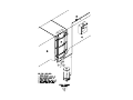
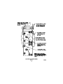
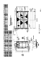
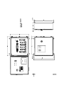
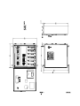
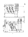
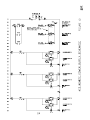
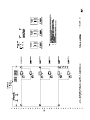
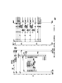
CUSTOM PACKAGED ELECTRONIC AIR CLEANER Model 75 Series Units WITHOUT Wash System • • • INSTALLATION OPERATION SERVICE For Model Numbers 75- ______-01 & -03 Electrostatic Precipitators for Commercial & Industrial Applications 101 McNeill Road • Sanford, NC 27330 (919) 775-2201 • Fax: (919) 774-8771 • (800) 884-0002 www.trioninc.com MANUAL PART NO. 154024-002• July 2002 Accepted For Use City of New York Department of Buildings MEA 288-01-E and 88-99-E TABLE OF CONTENTS SECTION I DESIGN For The System Design Engineer Page 1. General Description ................................................................................................................... 1 2. System Design and Layout........................................................................................................ 1 3. Outdoor Installations ................................................................................................................. 2 SECTION II INSTALLATION For The Installing Contractor 1. Unpack and Inspect ................................................................................................................... 2 2. Position Air Cleaner Cabinet ..................................................................................................... 2 3. Connect Adjoining Ductwork .................................................................................................... 2 4. Connect Drain............................................................................................................................. 3 5. Mount Controller/PWM Power Supply ...................................................................................... 3 6. Complete Wiring A. High Voltage Wiring................................................................................................................ 3 B. Primary Wiring ........................................................................................................................ 3 C. Grounding ............................................................................................................................... 3 7. Checkout for System Start-up................................................................................................... 3 SECTION III OPERATION AND SERVICE For The Maintenance Engineer 1. Introduction and Principle of Operation ................................................................................... 4 2. General Description ................................................................................................................... 4 3. Initial Start-up ............................................................................................................................. 4 4. Routine Maintenance ................................................................................................................. 5 5. Periodic Maintenance ................................................................................................................ 5 6. Trouble Shooting ....................................................................................................................... 6 7. Spare Parts ................................................................................................................................. 7 8. Troubleshooting Reference Chart............................................................................................. 8 9. Page 9 through 11 .................................................................................................... NOT USED SECTION IV REFERENCE Illustrations and Drawings Figure 1 Figure 2 Figure 3 Figure 4 Figure 5 Figure 6 Figure 7 Figure 8 Figure 9 Figure 10 Figure 11 Figure 12 Figure 13 Figure 14 Figure 15 Figure 16 Figure 17 General Component Arrangement...................................................... 12 High Voltage Lead Terminal Connections ......................................... 13 Typical Outdoor Installation................................................................ 14 Model 75 Junction Box… .................................................................... 15 Unit Outline .......................................................................................... 16 ATS Control Outline (STANDARD) ...................................................... I7 ATS PWM Remote Box (OPTIONAL) .................................................. 18 AIR BOSS CONTROL (OPTIONAL) ..................................................... 19 Not Used............................................................................................... 20 Not Used............................................................................................... 21 ATS Control (Standard)– Schematic .................................................. 22 ATS Control (Standard)– Field Wiring/ Sequence of Operations ..... 23 ATS Remote (optional)– Schematic.................................................... 24 ATS Remote (optional)– Field Wiring ................................................. 25 Air Boss Control (optional) – Schematic............................................ 26 Air Boss Control (optional) – Schematic/Field Wiring ...................... 27 Air Boss Control (optional)– Sequence of Operations...................... 28 SECTION I DESIGN If space prohibits, turning vanes, air baffles or other means may be utilized. Ducting – where attached to the cabinet collars – should be gasketed, caulked or otherwise made watertight. FOR THE SYSTEM DESIGN ENGINEER 1. General Description The standard major components supplied with each unit for installation are as follows: When there is a danger of rain, snow or debris being drawn into the system with outside air, the make-up air intake should be protected with rain louvers, hooding and hardware cloth to prevent the rain, snow or debris from entering the electronic air cleaner. electronic air cleaner controller / power supplies Contaminants to be collected – such as oils in vaporous state – must be condensed into particulate form prior to entering the ionizing-collecting cells in order to maintain the anticipated efficiency. Gases, vapors or any nonparticulate cannot be precipitated and will therefore pass through the air cleaner. Any condensing that takes place downstream from the air cleaner defeats the purpose. By the same token, heavy concentrations of water vapor, or other matter that becomes highly conductive when condensed, must be prevented from entering and/or condensing in the collecting elements to prevent electrical arc over and shorting. The electronic air cleaner contains the ionizingcollecting cells (collecting elements) and metal mesh pre-filters and after-filters. Perforated plate or impingement type mist suppressors, in lieu of the metal pre-filters, are options when specified. Gasketed access doors located on one end of the cabinet, 90 degrees to the direction of the airflow, provide entry for removal of the cells and filters. The location of the access doors may be specified as “right” or “left” handed. The hand designation is determined by standing in the ductwork on the air entering side of the unit so the airflow strikes your back. SAFETY NOTE: Factory designed access to all electrically charged high voltage components contain electrical interlocks for the safety of operating personnel. Any additional access that may be provided in the system, where there is access to high voltage, must be equipped with such interlocks. Interlocks are readily available from the factory. The Pulse Width Modulated (PWM) power supplies, providing the necessary high voltage for the air cleaner and the controls are furnished in a NEMA 12 enclosure designed for remote mounting. The distance between the controller and unit must be determined as the interconnecting high voltage leads are furnished to the specified length. Consult factory for distances greater than 50 ft. Cables are not to be spliced at any point along their length. In addition, the enclosure is a central junction for the primary wiring. Drain lines from the cabinet drain basin should be trapped or otherwise sealed against the system pressure (in accordance with local codes). Each installation varies according to needs, but normally the controller is located near the air cleaner. Ideal mounting height is at eye level for ease in reading the instrumentation, and to facilitate service. Note: Trion Tridex Detergent is specially formulated for use with Trion electronic air cleaners. Use of other cleaners and detergents, not specifically approved by Trion, can cause possible failures in the unit and will void any and all warranties on our equipment. For ease in maintenance and component removal, adequate space, 39” Minimum Required, must be provided in front of all access doors, motors, pump and accessory equipment. Special consideration should be given in this respect for installations where the unit is suspended overhead. Catwalks or platforms should be provided. 2. System Design and Layout The arrangement of the supplied components and the general layout of the system will vary according to application, adjoining equipment and available space. However, there are several basic factors pertaining to all installations that must be considered: CAUTION In addition to the above space requirement, installation of the Model 75 in NFPA applications shall have a clearance of at least 18"”to a combustible material, 3" to limited combustible material, and 0” to noncombustible material. Any reduction in clearance or exceptions must be in compliance with NFPA and acceptable to the Authority Having Jurisdiction. To maintain the selected cleaning efficiency, it is important to assure that the total air volume (capacity in CFM) is uniformly distributed across the entire face area of the unit. The metal mesh filters, perforated plate or mist suppressors; provide some resistance to effect even air distribution. However, since most air ducts are designed to handle air velocities greater than the rated velocity of the air cleaner, it is necessary to properly transition any attached ducting. If possible, a contraction ratio of 1 in 3 (approximately 20°) should be maintained. 1 Preferably, straight down from the drain pan supply through the floor. The normally recommended drain line trap, to seal off the cabinet from the drain against the system pressure, should be located in the heated interior. If not installed in this manner, heat wrap or other means should be employed to prevent freezing. Clean-outs are recommended to be installed in all drain lines. ****WARNING**** Fire Suppression Systems Extreme caution should be exercised when this unit is installed in applications that are collecting volatile or potentially flammable contaminates such as cooking grease and petroleum based oils. Trion strongly recommends a fire suppression system be installed in the ductwork and on the Model 75 in cases where these contaminates are collected on the cell plates and collect on the attached ductwork. Contact the factory for questions or concerns regarding a fire suppression system. SECTION II INSTALLATION FOR THE INSTALLING CONTRACTOR 1. Unpack and Inspect At the time the unit is received, all shipping containers and their contents should be examined for damage. Any damage occurring in shipment must be immediately reported to the carrier, an inspection report completed and a claim filed at the receiving point. 3. Outdoor Installations Requirements for outdoor protection vary in accordance to climate and equipment component arrangement for the particular job. The best approach, for equipment protection, is the construction of a heated shed or building over the installation. As an alternative, the installing contractor should treat the equipment as required to meet the specific needs. Detailed discussions of the Model 75 components are as follows, using a rooftop installation as an example (refer to Figure 3): The unit cabinet is shipped completely assembled and, where size permits, the ionizing-collecting cells are shipped inside the cabinet. On large units, the upper tier of cells may be shipped in separate containers. The controller, and other separate accessories are shipped in the containers as noted on the packing list. Adjoining Duct Work (not supplied by Trion) The ductwork located on the air entering side of the cabinet, between the point where it enters the roof and the cabinet, must be air tight to prevent the entrance of moisture, especially if it is under negative pressure. It must also be adequately insulated or other means taken to prevent the formation of condensation through temperature change. Condensation will short out the ionizing-collecting cells. Insulation must be of the outdoor variety. 2. Position Air Cleaner Cabinet To reduce weight for ease in handling, remove the prefilters, after-filters and the ionizing-collecting cells from the cabinet, and place them safely aside. Position the cabinet in the designated location giving consideration to the following points: (a) Provide sufficient clearance in front of the access doors for ionizing-collecting cell and mechanical filter removal. A minimum of 39 inches is required. (see figure 5) (b) Level the cabinet to assure proper drainage from the drain pan. (c) Unless specific design features have been prearranged, the direction of airflow through the cabinet may be either from the right or the left. When the ionizing-collecting cells are reinstalled, the directional arrows on the cell end plates must concur with airflow through the cabinet. If mist suppressors have been specified, they are to be installed on the air entering side of the unit. Trion Model 75 Cabinet The access doors on the Model 75 cabinet are gasketed and the unit is basically sealed against air leakage. The paint finish (epoxy) is for interior and exterior use. Like the air-entering duct, the cabinet must be insulated or other means taken to prevent condensation from taking place, which results in electrical shorting of the ionizingcollecting cells. Insulation, when employed must be suitable for outdoor applications and when applied, consideration given to all access door openings and electrical interlock box covers. Controller/PWM Power Supplies As the controller/power supplies are designed for remote mounting, they can be, in many cases, located indoors and still be reasonably close to the main cabinet. If located outdoors with the cabinet, it must be weather protected. After the cabinet has been properly located, it may be secured into place at the predrilled factory mounting pads either by bolting or welding. 3. Connect Adjoining Duct Work Depending on the application, the installation plan may or may not call for adjoining ductwork on the air entering and/or air leaving sides of the cabinet. Drain Line The drain line, located under the ionizing/collecting cell access door at the lowest point of the Trion cabinet drain pan, should be piped with as short a run as possible to the heated interior of the building. When adjoining ducting is to be installed, the bottom of the horizontal duct runs should be relatively flat and 2 one Red for the collector, are factory furnished. Each lead is to be run in separate conduit and must be of continuous run (do not splice) between the controller and the ionizing-collecting cell terminal connection in the junction box. sloped toward the cabinet drain pan for an 18-inch length. Duct securement to the collar may be completed using the predrilled flange. The seam should be made air and watertight by caulking or gasketing. (b). Primary Wiring The Controller is the main distribution point for all primary wiring. The various electrical components involved are connected to and powered from the controller. These interlocks are safety switches that prevent access to the charged high voltage components without first turning “OFF” the high voltage by interrupting the 24 VDC input to the PLC. Refer to the appropriate Field Wiring Diagram. When a blower is installed downstream from the Trion cabinet, the ducting between the cabinet and the blower will be under negative pressure and should be made air tight to prevent infiltration of contaminated air. After the ductwork has been installed, clear remaining material or debris from inside ducts and bottom of cabinet, and then re-install both the mechanical filters and the ionizing-collecting cells. (c). Grounding An earth ground must be provided to the Model 75 cabinet and control. All ground connections must be in contact with bare metal and securely affixed. Ground conductor size and connection means will be in accordance with all applicable electrical code standards. NOTE: Follow the directional arrows located on the cell end plates. The side of each cell containing the spiked ionizer blades must be located on the air entering side of the cabinet. The brass contact plungers on the cell should be inserted toward the back of cabinet. Also, mist suppressors when specified must be located on the air entering side of the cabinet. 7. Check Out for System Start-up When the installation has been completed, assure that the equipment is ready for start-up by checking the following: 4. Connect Drain Connect a drain line to the pipe coupling provided in the cabinet drain basin in accordance with the governing plumbing codes. The drain line must be sealed with a trap or other means to prevent air by pass. If a trap is used, it should hold sufficient water column to overcome the system air pressure and to assure that loss of liquid from evaporation between cleaning periods will not break the seal. The drain line should not be smaller than the drainpipe coupling. A. All construction debris is removed from the ionizingcollecting cells, drain basin and ductwork. B. The drain line from the Trion drain basin is clear and completely connected to its point of termination. C. Supply line power is available and electrical wiring is completed to the following components: 5. Mount Controller The Controller should be mounted at eye level and located as close to the air cleaner as practical. It must be mounted indoors out of the weather unless supplied with a weatherproof cabinet. Allow sufficient space in front of the access door(s) for service. Refer to appropriate Control/Remote PWM Box Outline Drawing for mounting hole layout and dimensions. 1. 2. 3. 4. Controller Electrical Interlocks Ionizing-Collecting Cells The System Fan SECTION III OPERATION & SERVICE 6. Complete Wiring (a). High Voltage Wiring WARNING RISK OF ELECTRIC SHOCK These serving instructions are for use by qualified personnel only. To reduce the risk of electric shock, do not perform any servicing other than that contained in the operating instructions unless you are qualified to do so. WARNING: EXERCISE ALL THE NORMAL PRECAUTIONS WHEN WORKING WITH HIGH VOLTAGE AND COMPLY WITH NEC AND ALL APPROPRIATE LOCAL CODES. The high voltage wiring entails interconnecting the power supply(s) to the ionizing-collecting cell(s) through the factory-installed junction box on top of the cabinet. All the wiring in the cabinet has been completed at the factory. FOR THE MAINTENANCE ENGINEER 1. Introduction and Principle of Operation The Trion electronic air cleaner is technically known as an electrostatic precipitator. In this type of equipment, all airborne particles, even of microscopic Refer to the Field Wiring Diagram. Two high voltage leads, Red/Black Tracer for the ionizer and 3 size, are electrically charged (positively) as they pass through a high voltage ionizer. These charged particles are then attracted and adhere to a series of parallel collecting plates, which form the negative elements of an electrostatic field. are required for the ionizer sections and 6.5 KVDC for the collector sections of the cells. The ionizer consists of charged stainless steel spiked blades spaced between grounded electrodes. The collecting section consists of parallel plates arranged so that each alternate plate is charged while the intermediate plates are electrically grounded. A. Inspect the inside of the adjoining ductwork and Trion cabinet to be sure it is clean and free of any debris or construction materials. Especially note the opening in the drain basin for any restrictions. The ducting, where secured to the cabinet collars, should be sealed water tight either with gasketing or caulking. 3. Initial Start-up Periodically, depending on the type and concentration of contamination in the air, contaminate is washed from the plates by manually removing the cells and washing with a pressure washer. B. Inspect the ionizing-collecting cells to see that all of the ionizing blades are intact, that no large pieces of foreign material are lodged between the plates, and that the cells are properly installed in the cabinet with the spiked ionizing blades located on the air entering side. Two major functional components comprise the air cleaner: (1) Ionizing-collecting cells to ionize and collect airborne particulate matter. (2) Power supply(s) to supply high voltage direct current to the ionizing-collecting cells. C. Check the high voltage leads to see that they are connected to the proper terminal both at the ionizing-collecting cells, the junction box and inside the controller. (Refer to Figures 2 and 4). Normally, systems are designed for collection efficiencies in the range of 90 percent or more. Collecting a contaminate at these efficiencies, especially when there are high concentrations can result in large accumulations in a relatively short period. Therefore, maintenance must encompass two areas; the operation of the equipment for efficient collection and the systematic removal of the collected contaminate. D. Be sure that the drain lines from the Trion cabinet drain basin are completely connected and properly terminated. A trap or seal of some type should be incorporated in the line to prevent air bypass. E. Be sure that electrical power is available, that the wiring is completed, and that the system blower is ready to energize. 2. General Description The ionizing-collecting cells (contaminate collecting elements) are housed in the cabinet on slide rails. They can be removed from the cabinet as required, through the end access door, by sliding them out like drawers. On multi-cell units, all of the electrical connections between cells in a given tier are automatically made through spring plunger connectors. On the access end, the high voltage cables from the power supplies are connected to the junction box on top of the cabinet. The high voltage cables from the junction box to the individual tiers are factory wired. When installing cells into the cabinet, observe the directional arrows on the cell end plates. The side of the cell containing the spiked ionizer blades always must be located on the air entering side. The spring plunger connectors, located on one end of each cell, will always face toward the back of the Model 75 Cabinet. F. Be sure that all access door interlocks are closed. G. Close the system electrical supply switches, making power available to the Trion controller and the system fan. H. Turn the controller selector switch to the “ON” position. The blower should run (if installed) and the power supply(s) should be energized. Electrical arcing within the ionizing-collecting cells may occur. It is a normal occurrence caused by accumulation of dusts from construction or other sources in the cell(s) and should subside quickly. If the arcing is continuous and does not subside, recheck the routing of the high voltage leads between the power supply(s) and the cell(s). Refer to the field wiring diagram. The ionizer lead must be connected to the ionizer and the collector lead to the collector. Both the air entering and air leaving side of the cabinet contain either metal mesh filters or perforated plate, whichever was specified. These items act as trash screens, and provide resistance for even air distribution. Kitchen Exhaust Applications I. For safe and proper operation adhere to the following instructions and procedures: The Power Supply(s) convert the 115 volt, 60HZ, single phase AC supply to the high voltage DC needed to power the ionizing-collecting cells. Potential of 13 KVDC 1. Exhaust systems shall be operated during all periods of cooking in restaurant applications. 4 The ATS controller and remote PWM box both have LED indicating lights to show power to the PWM power supplies. Flickering or failed LED’s indicate electrical arcing and/or power failure. 2. Filter-equipped exhaust systems shall not be operated with filters removed. 3.The posted instructions for manually operating the fire extinguishing system shall be kept conspicuously posted in the kitchen and reviewed periodically with employees by the management. 5. Periodic Maintenance A. Fire Suppression System (IF INSTALLED) – Every 6 Months Properly trained and qualified personnel shall complete inspection, cleaning and servicing of the fire suppression system. 4. Listed exhaust hoods shall be operated in accordance with the terms of their listings and the manufacture instructions. All actuation components, including remote manual pull stations, mechanical or electrical devices, detectors, fire-actuated dampers, etc., shall be checked for proper operation in accordance with the manufacturers listed procedures. In addition to these requirements, the specific inspection requirements of the applicable NFPA standard shall also be followed. If required, certificates of inspection and maintenance shall be forwarded to the authority having jurisdiction. 5. Cooking equipment shall not be operated while its fire-extinguishing system or exhaust system is not operating or otherwise impaired. 4. Routine Maintenance A. Washing Frequency The frequency that the collected dirt is to be washed from the unit depends upon the type and amount of dirt in the air to be cleaned. Dirt which is greasy in nature tends to harden after collection and should be washed away often. Likewise, units operating under extremely heavy dirt loads should be washed more often as a large build-up of collected material will have a tendency to “blow-off” if permitted to remain on the collecting elements for long periods of time. In that the type and amount of dirt varies geographically (and from one location to another in any given area) it is recommended to start operation with a washing frequency of at least once a week. This schedule may then be altered as needed after visual examinations of the collected material contained on the ionizing-collecting cells. Daily washing is not unusual for units operating on heavy welding fume, kitchen exhaust hoods or similar contaminants. B. Controller Every 12 Months The inside of the controller cabinet should be examined for accumulated dirt and dust. If required, the components should be cleaned using a good brand of electrical contact cleaner. All terminal connections should be checked for securement and tightened or reworked as required. C. Ionizing-Collecting Cell – Every 6 to 12 Months Remove and inspect the ionizing-collecting cells for excessive dirt accumulations. Manually clean as required in a soak tank, commercial car wash, or with a pressure hose or pressure cleaner using a low pressure setting. At this time, particular care should be taken in cleaning each of the insulators. WARNING: DO NOT USE HIGH PRESSURE STEAM CLEANING EQUIPMENT TO CLEAN CELLS. THE EXCESSIVE HEAT AND PRESSURE WILL CAUSE THE PLATES TO WARP AND IN TURN POSSIBLY CAUSE EXCESSIVE ARCING. B. Detergent Effective washing is dependent upon detergent. The detergent, as supplied by Trion, Inc., is formulated specifically for electronic air cleaners. If substitutes are used, they must be approved by Trion, so as to not void the warranty and should be safe for use in ventilation systems and non-caustic, as 95% of the ionizing-collecting cells are constructed of aluminum and special high voltage insulation and gasket seals. D. Filter Devices – Every 4 to 6 Months Hoods, impingers, metal mesh filters, ducts and other appurtenances shall be cleaned to bare metal at frequent intervals prior to surfaces becoming heavily contaminated with grease, oil or other contaminate. It may be advantageous to clean readily removable items, such as impingers, metal mesh filters or other permanent filter devices in a soak tank, with a pressure hose or pressure cleaner set low. After cleaning to bare metal, components shall not be coated with powder or other substance. C. Electrical Operation The Air Boss controller (Optional) contains a digital LED display for kilovolt and milliampere readings. The milliammeter should be observed on a routine basis to be sure that it is reading within the prescribed operating range as marked on the data plate. For those units containing a voltmeter, the ionizer readings should be between 12.5 and 13.5 KV. 5 When a cleaning service is used, a certificate showing dates of inspection and/or cleaning shall be maintained on the premises. WARNING Flammable solvents or other cleaning aids shall not be used. power supply and the ionizing-collecting cell(s) they energize. The quantity of power supplies per unit is dependent upon unit size with one or two power supplies for each ionizing-collecting cell tier in height. Other than the basic hand tools, it is advantageous to have a volt meter with a 20 KVDC high voltage probe. These instruments are standard catalog items by several manufactures. flammable At the start of the cleaning process, electrical switches that could be accidentally activated shall be locked out. Components of the fire suppression system (if installed) shall not be rendered inoperable during the cleaning process. B. Secondary Short Circuit The most common outage is a short in the secondary circuit and is best located through the process of elimination. Symptoms are a flickering indicating light accompanied by an arcing noise in the ionizing-collecting cell(s) or an indicating light that is not glowing. Care should be taken not to apply cleaning chemicals on any fusible links or other detection devices of the automatic extinguishing system. A flickering light with an arcing noise is an indication of a high resistance short circuit and a light that is not glowing is an indication of a dead short. (A light that is not glowing can also be an indication of an open circuit in the primary circuit. Refer to the paragraph on open circuits.) The short may be in the power supply, the high voltage cables or the ionizing-collecting cell(s). To isolate the short to any one of these three components, proceed as follows: 6. Troubleshooting WARNING: EXERCISE THE USUAL PRECAUTIONS WHEN WORKING WITH HIGH VOLTAGE. THE MAXIMUM OPERATING OUTPUT FROM THE POWER SUPPLY IS 15,000 VDC AND 5.5 MA. to 11.0 MA. WHEN IN PARALLEL. WARNING IF SAFETY SWITCHES ARE CLOSED AND CIRCUIT IS ENERGIZED, DO NOT TOUCH HIGH VOLTAGE. WHEN THE CIRCUIT IS DE-ENERGIZED, ALWAYS BLEED OFF REMAINING STATIC CHARGE WITH AN INSULATED HANDLED SCREW DRIVER BY SHORTING GROUND When safety interlock switches are closed, do not come in contact with high voltage components. The operating output from the high voltage power supply(s) is 12,600 VDC and 6 MA. to 11.0 MA. THE POINTS OF HIGH VOLTAGE DC POTENTIAL. When the power supply(s) is de-energized there is a 20 second delay for the voltage to decay. Always short from ground to a point of high voltage with a well insulated jumper wire or an insulated handled screwdriver to bleed-off any remaining residual charge. WARNING Risk of Electrical Shock The servicing Instructions are for use by qualified personnel only. To reduce the risk of electric shock, do not perform any servicing other than that contained in the service instructions unless you are qualified to do so. A. Introduction This section on trouble shooting provides a description of potential malfunctions, their cause, location and correction. A Trouble Reference Chart listing the most probable causes and corrections follows the general text. 1. Disconnect both high voltage leads from their respective terminals in the power supply and support them away from any point of contact. 2. Energize the power supply: a. If the light still flickers or does not glow, the trouble is indicated to be in the power supply. Replace the power supply in its entirety. NOTE: All repair to the fire suppression system (If Supplied) must be completed by the authorized fire control contractor. b. If the light glows steady with the leads disconnected the power supply is indicated to be normal. NOTE: It will be necessary to close the access door electrical interlock switch operated by the access door and affix the junction box lid with hardware supplied to close the electrical interlock switch on the box, to complete the primary circuit to the power supply. The electronic air cleaner is the unit within the system that has the highest efficiency collection rating and is also the one with the highest potential for malfunction. When a malfunction does occur, the outage is usually found in the electrical secondary circuit in the ionizing-collecting cell(s). 3.Next reconnect both high voltage leads to their respective terminals inside the power supply and disconnect them at the ionizing-collecting cell(s). Support Indicating lights are installed in the face panel of the control to monitor the electrical operation of each 6 (4) Outage in the power supply. Look for charred or burned components or a loose wiring connection. Replace power supply or reconnect wiring. (5) Defective indicating light. Replace light. them away from any point of contact and energize the power supply. a. If either high voltage lead is defective the light will indicate the trouble. Each lead may then be checked separately by disconnecting them, one at a time, from their respective terminals at the power supply. When a lead is found to be defective, replace it in its entirety. Do not repair or splice. d. Malfunctions other than short or open circuits. Refer to trouble reference chart in this section. b. If the light glows steady with the leads disconnected at the ionizing-collecting cell(s) the trouble is then indicated to be in the ionizing-collecting cell(s). 7. Spare Parts Recommended spare part quantities are usually based on the unit size and the amount of units per installation. For specific recommendations, consult the Trion factory or nearest Sales Office. Consideration, however, should be given to stocking the following components; The trouble can then be isolated to, a single cell, or the ionizing or collector section of a given cell as follows: (1) First determine if the short is in the ionizing section or the collecting section by connecting each high voltage lead to its respective section, one at a time, and energizing the power pack. (The lead not connected must be supported away from any point of contact.) The short symptoms will still exist for the section in which the short is located. If the trouble causing the short is bridging both sections, then the short will be indicated in both sections when they are individually connected. (2) When the short is isolated to a cell tier, remove all the cells within the tier and visually check the sections indicated to contain the short. (a). If the short is in the ionizer section look for a broken or defective insulator. (b). If the short is in the collector section look for a large piece of foreign material bridging the collector plates or a defective insulator. (c) . If the short is indicated to be in both sections, it will probably be a foreign object bridging the air gap between the ionizer and the collector. DESCRIPTION PWM Power Supply Junction Box Stand Off Insulators Cell Insulators LED QTY. 2 2 6 2 Part Numbers are not listed as they are subject to change. Always state Unit Model and Serial Numbers when ordering parts. c. Open Circuits Although open circuits can occur in the secondary they usually take place in the primary. If the unit contains only one power supply and the indicating light does not glow the outage is probably one of the following. (1) Supply line power to the control disconnected. Reconnect. (2) Open access door interlock in control of electronic air cleaner. Be sure all access doors are properly closed and secured. (3 )Blown in-line fuse located on the power supply circuit board. Replace power supply. 7 Troubleshooting Reference Chart PROBLEM/ SYMPTOM PROBABLE CAUSE LOCATION REASON - CORRECTION Ionizing Section of Cell 1. 2. 3. Collecting Section of Cell 1. 2. 3. 4. 1. Short Circuit High Voltage Leads Indicating Light Not Glowing 2. Power Supply Control 1. 2. 1. 2. 3. Power Supply Indicating Light Not Glowing Open Circuit Electronic Air Cleaner Housing 1. 2. 3. 1. 2. Indicating Light Flickering High Resistance Short High Voltage Circuit 3. 4. 5. 8 Dirty insulator(s) – Clean Defective insulator(s) – Replace Foreign Object Between Ionizing Bar and Ground electrode - Remove Dirty insulator(s) - Clean Defective insulator(s) – Replace Foreign Material Bridging Plates - Remove Bent Plates – Straighten or Replace Disconnected High Voltage Lead Contacting Ground - Reconnect Defective Lead/Insulation Breakdown – Replace Entire Lead Charred/Over Heated Components – Replace Power Supply Disconnected Supply Line Power – Reconnect Faulty indicting Light - Replace Blown In-line Fuse – Replace Power Supply Disconnected Wire – Replace Charred/Over Heated Components – Replace Power Supply Electrical Interlock Switch Not Closed – Close Access Door Junction Box interlock switch not closed – Secure Cover Faulty Electrical Interlock Switch - Replace Ionizer High Voltage Lead Connected to Plate Section and Plate Lead to Ionizer – Reconnect Leads Loose or Disconnect high Voltage Lead-Tighten or Reconnect Loose or Defective Intercell Connection (on Multicell Units) – Tighten or Replace Foreign Object Adrift in Ionizer or Plate Section of Cell – Remove Dirty Cells – Remove, clean and replace.