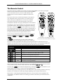
1
O
W
N
E
R
S
M
A
N
U
A
L
Model:
HIRD-B1
Trademarks and Copyrights—
Software contained in the receiver and this manual is
copyright © 1995, 1996, 1997, and 1998 by Hughes
Network Systems. Some features are patent pending.
WatchWord, PreSelect, LogoBelt, TurboTune, and
OneLine Guide are trademarks of Hughes Network
Systems. DIRECTV and DIRECT TICKET are trademarks
of DIRECTV, Inc., a Hughes Electronics Company and are
used with permission. USSB and USSB Entertainment Plus
are registered trademarks of U. S. Satellite Broadcasting
Company, Inc. NFL Sunday Ticket is a registered
trademark of the NFL Enterprises, L.P. NBA League Pass
is a trademark of NBA Properties, Inc. NHL Center Ice is a
registered trademark of the National Hockey League. ESPN
Full Court is a trademark of ESPN Enterprises, Inc. ESPN
Enterprises, Inc. is a wholly owned subsidiary of ESPN,
Inc. MLB Extra Innings SM is an official service mark of
Major League Baseball Properties, Inc. All other
trademarks and service arks are the property of their
respective owners.
Satellite Programming—For subscription information,
or to resolve problems related to satellite programming, call
the service providers, including DIRECTV at
1-800-DIRECTV (347-3288) and USSB at
1-800-204-USSB (8772).
Hardware and Installation—To arrange for
professional installation of your DIRECTV System, ask
questions, or to resolve problems related to your DIRECTV
System, contact your dealer. If additional information is
needed, please contact the Customer Care Center toll free at
1-800-274-8995.
Hughes Customer Care Center
1-800-274-8995
Subscriptions and PPV
1-800-DIRECTV or 1-800-204-USSB
This product is the subject of one or more U.S. or foreign
patents pending.
Disclaimer—Every effort has been made to ensure the
correctness and completeness of the material in this
document. No company shall be liable for errors contained
herein. The information in this document is subject to
change without notice. No warranty of any kind is made
with regard to this material, including, but not limited to,
the implied warranties of merchantability and fitness for a
particular purpose.
StarSight Information—StarSight ® features licensed
under one or more of the following U.S. patents: 4,706,121;
5,151,789; 5,335,277; 5,353,121; 5,479,266; 5,479,268;
and 5,532,754. Use rights reserved.
Macrovision Information—This device incorporates an
anticopy process technology that is protected by U.S.
patents and other intellectual property rights. The anticopy
process is licensed for noncommercial, home use only.
Reverse engineering or disassembly is prohibited.
Note on Recording Programming—Most television
programs and films are copyrighted. This means that
someone has legal rights governing the reproduction and
distribution of this material. In certain circumstances,
copyright law may apply to private in-home taping of
copyrighted materials. In most cases, it is permissible to
record for personal use, as long as you do not sell the
material. You must act responsibly in this area - check into
the matter if you are unsure.
Some pay per view programs may be licensed from
producers as “view only” programs. These are copyrighted
programs and may not be copied or reproduced for any
purpose without the express written permission of the
copyright owner.
PLEASE MAKE NOTE OF THE FOLLOWING
INFORMATION FOR WARRANTY
System Model #: HSYS- ____ ____ ____ ____ ____
Receiver Model #: HIRD- B1
Receiver Serial #: ___________________________
Access Card #: __________ __________ __________
LNB Model #: _______________________________
LNB Serial #: ________________________________
IMPORTANT SAFETY INSTRUCTIONS
For your safety and protection, read this entire Owner’s Manual before you attempt to install or use the DIRECTV System. In
particular, read this safety section carefully. Keep this safety information where you can refer to it if necessary.
INSTALLATION
Polarization—This product is equipped with a plug that
will fit into the power outlet only one way. Do not modify
the plug defeating this feature. If the plug does not fit,
contact your electrician to replace your outlet. To prevent
electric shock, do not use this plug with an extension cord
or outlet unless you can fully insert the blades without
blade exposure.
Power Sources—Operate this product only from the type
of power source indicated on the marking label. If you are
not sure of the type of power supply to your home, consult
your dealer or local power company.
Ventilation—Do not block the ventilation slots and
openings in the case. Do not block these openings by
placing the product on a bed, sofa, rug, or other similar
surface. Do not place this product near or over a radiator or
heat register, or in a built-in installation such as a bookcase
or rack unless proper ventilation is provided.
For electrical safety, power line operated equipment or
accessories connected to this unit should bear the UL
listing mark or CSA certification mark and should not
be modified so as to defeat the safety features. This will
help avoid any potential hazard from electrical shock or
fire. If in doubt, contact qualified service personnel.
Accessories—To avoid personal injury or damage to the
receiver, do not place the digital satellite receiver on any
unstable cart, stand, table, or bracket. Any mounting of the
product should follow the manufacturer’s instructions.
Attachments—Do not use attachments unless
recommended by the product manufacturer as they may
cause hazards.
Satellite Dish Antenna Grounding—The outdoor
antenna used to receive satellite signals and the cable used
to connect the antenna to the indoor receiving unit are
required to comply with local installation codes and the
appropriate sections of the National Electric Code (NEC)
and in particular Article 810-15, which covers proper
installation and grounding of television receiving
equipment, as well as to Article 820-33, which specifies
that the satellite dish cable ground shall be connected to the
grounding system of the building as close to the point of
cable entry as practical. These codes require proper
grounding of the metal structure of the outdoor antenna and
grounding of the connecting cable at a point where it enters
the house (or other building). If you are having a
professional installer make the installation, the installer
must observe installation codes. This manual contains
instructions on how to make the installation in compliance
with the NEC. If additional local installation codes apply,
contact local inspection authorities.
EXAMPLE OF ANTENNA GROUNDING ACCORDING
TO THE NATIONAL ELECTRICAL CODE
INSTRUCTIONS CONTAINED IN “RADIO AND
TELEVISION EQUIPMENT”
Water and Moisture—Do not use this product near
water or moisture.
Television Antenna Information—Installing an
outdoor antenna can be hazardous and should be left to a
professional antenna installer. Do not locate the outside
antenna system in the vicinity of overhead power lines or
other electric light or power circuits, or where it can fall
into such power lines or circuits. When installing an outside
antenna system, take extreme care to keep from touching
such power lines or circuits as contact with them might be
fatal. If an outside antenna is connected to the digital
satellite receiver, be sure the antenna system is grounded so
as to provide some protection against voltage surges and
built-up static charges. Section 810 of the NEC, NFPA No.
70 1987, provides information with respect to proper
grounding of the mast and supporting structure, grounding
of the lead-in wire to an antenna discharge unit, size of the
grounding conductors, location of antenna discharge unit,
connection to grounding electrodes, and requirements for
the grounding electrode.
Power Lines—Extreme care must be taken when
installing and adjusting or maintaining the outdoor antenna
and connecting cable, especially in the vicinity of overhead
power lines, electric lights, or power circuits. When
installing the outdoor antenna or cable, extreme care should
be taken to keep from touching or approaching such power
lines or circuits, as contact with them might be fatal.
Cleaning—Unplug this product from the wall outlet
before cleaning. Do not use liquid cleaners or aerosol
cleaners. Use a damp cloth for cleaning.
Object and Liquid Entry—Never push objects of any
kind into this product through openings as they may touch
dangerous voltages or “short out” parts that could result in
a fire or electric shock. Never spill liquid of any kind on the
product.
SERVICE
Servicing—Do not attempt to service this product
yourself as opening or removing covers may expose you to
dangerous voltage or other hazards. There are no user
serviceable parts inside. Refer all servicing to qualified
service personnel.
Conditions Requiring Service—Unplug this product
from the wall outlet and refer servicing to qualified service
personnel under the following conditions:
•
When the power supply cord or plug is damaged.
•
If liquid has been spilled on, or objects have fallen
into, the product or it has been exposed to water.
•
If the product does not operate normally by following
the operating instructions. Adjust only those controls
that are covered by the operating instructions.
Improper adjustment of other controls may result in
damage and will often require extensive work by a
qualified technician to restore the product to its normal
operation.
For your own safety, follow these important
safety rules:
•
If the product has been dropped or the cabinet has
been damaged.
•
When the product exhibits a distinct change in
performance.
Replacement Parts—When replacement parts are
required, have the service technician verify that the
replacements being used have the same safety
characteristics as the original parts. Use of replacement
parts specified by the product manufacturer can prevent
fire, electric shock, or other hazards.
Safety Check—Upon completion of any service or
repairs to this product, ask the service technician to perform
safety checks recommended by the manufacturer to
determine that the product is in safe operating condition.
THESE ARE DEFINITIONS FOR ALERTS USED
IN THIS MANUAL
THESE ALERTS APPEAR IN THIS MANUAL
WARNING
•
Perform as many functions as possible
on the ground.
•
Do not install the antenna on a rainy or
windy day.
•
If you start to drop the antenna or mast
assembly, get away from it and let it fall.
DANGER
Do not select a location to install the satellite
dish/antenna near power lines. You can be
killed if the dish/antenna comes into contact
with electric power lines.
•
Do not contact overhead power lines
•
Check the distance to any nearby power
lines before starting installation. Stay at
least 20 feet away from all power lines.
•
If any part of the antenna or mast
assembly comes into contact with a
power line, call your local power
company. Do not try to remove it
yourself. They will remove it safely.
WARNING or CAUTION
CAUTION
Where you see this alert symbol
and the WARNING or CAUTION
heading, strictly follow the warning
instructions to avoid personal injury.
Local electric codes and the National Electric
Code (NEC) require the antenna to be
grounded. Grounding the antenna helps
protect against damage caused by static
voltage buildup. Grounding can also protect
against voltage surges created by nearby
lightning strikes.
DANGER
Electric shock hazard: Where you
see these symbol and the DANGER
heading, strictly follow the warning
instructions to avoid electric shock
injury
FEDERAL COMUNICATIONS COMMISSION (FCC)
REGULATORY INFORMATION
Federal Communications Commission (FCC)—The
system complies with both Part 15 and Part 68 of the FCC
rules.
not done, the telephone company may temporarily
disconnect service.
3.
The telephone company may make changes in its
technical operations and procedures; if such changes
affect the compatibility or use of this device, the
telephone company is required to give adequate notice
of the changes. You will be advised of your right to
file a complaint with the FCC.
4.
If the telephone company requests information on
what equipment is connected to their lines, inform
them of:
Part 15 compliance—
This equipment has been tested and found to comply with
the limits for a Class B digital device, pursuant to Part 15
of the FCC rules. These limits are designed to provide
reasonable protection against harmful interference in a
residential installation. This equipment generates, uses and
can radiate radio frequency energy and, if not installed and
used in accordance with the instructions, may cause
harmful interference to radio communications.
However, there is no guarantee that interference will not
occur in a particular installation. If this equipment does
cause harmful interference to radio or television reception,
which can be determined by removing and applying power
to the equipment, the user is encouraged to try to correct
the interference by one or more of the following measures:
•
Reorient or relocate the receiving antenna.
•
Increase the separation between the equipment and the
receiver.
•
Connect the equipment into an outlet on a circuit
different from that to which the receiver is connected.
•
Consult the dealer or an experienced radio/TV
technician for help.
The user may find the following booklet, prepared by the
Federal Communications Commission, helpful: “How to
Identify and Resolve Radio and TV Interference
Problems.” This booklet is available from the U.S.
Government Printing Office, Washington, DC.
To meet FCC requirements, only peripherals (computer
input/output devices, terminals, printers, etc.) certified to
comply with the Class B limits may be attached to this
device. Operation with non-certified peripherals is likely to
result in interference to radio and TV reception.
To meet FCC requirements, shielded cables are required to
connect the device to a personal computer, peripheral, or
other Class B certified device.
Part 68 compliance—
1.
The FCC has established Part 68 of the FCC Rules,
which permit this device to be directly connected to
the telephone network. Standardized jacks are used for
these connections. This equipment should not be used
on coin lines or party lines.
2.
If this device is malfunctioning, it may also be causing
harm to the telephone network; this device should be
disconnected until the source of the problem can be
determined and until repair has been made. If this is
•
the telephone number this unit is connected to.
•
the ringer equivalence number (REN). The
number can be found on a label located on the
bottom of the equipment.
•
the Universal Service Order Code (USOC) jack
required. This equipment requires a USOC RJ11
jack.
•
the FCC registration number. The number can be
found on a label located on the bottom of this
equipment.
TABLE OF CONTENTS
THE HUGHES-BRAND DIRECTV SYSTEM..1-1
What You Should Do First.................................1-1
How Does All This Work?.................................1-1
DIRECTV SYSTEM COMPONENTS........................1-2
The Satellite Antenna..........................................1-2
The Digital Satellite Receiver ...........................1-2
The Remote Control............................................1-4
SETTING UP YOUR DIRECTV SYSTEM........2-1
CHOOSING THE BEST CONNECTIONS .....................2-1
Hook Up the Audio/S-video Signals.................2-2
Hook Up the Audio/Video Signals....................2-3
Hook Up the RF Signals.....................................2-3
Finishing Up.........................................................2-4
INSTALLING REMOTE CONTROL BATTERIES.........2-4
NOW YOU CAN TURN IT ON ...................................2-4
CONTROLLING THE DIGITAL SATELLITE
RECEIVER ..................................................................3-1
FRONT PANEL VS. REMOTE CONTROL KEYS........3-1
BASIC NAVIGATION ..................................................3-1
INSTALLING AND POINTING YOUR
SATELLITE DISH....................................................4-1
DETERMINE W HERE TO POINT YOUR SATELLITE
DISH ............................................................................4-2
The INSTALLATION screen ..............................4-2
ALIGNMENT RESULT Pop-up Panel.............4-2
CHOOSING THE ANTENNA INSTALLATION SITE ...4-2
SELECTING A M OUNTING OPTION..........................4-5
INSTALLING THE A NTENNA ONTO A W OODEN
SURFACE ....................................................................4-6
INSTALLING THE A NTENNA ONTO A BRICK
SURFACE ....................................................................4-8
INSTALLING THE A NTENNA ONTO A CINDER BLOCK
SURFACE ....................................................................4-9
INSTALLING THE A NTENNA ONTO A M ETAL POLE ..
...................................................................................4-11
ATTACHING THE REFLECTOR ONTO THE LNB
SUPPORT A RM .........................................................4-12
Assembling the HANT-3_S Antenna ............. 4-12
ATTACHING THE A NTENNA A SSEMBLY TO THE
M AST OR POLE ........................................................4-12
GROUNDING THE M ETAL POLE M OUNT ..............4-13
GROUNDING THE BASE PLATE..............................4-13
INSTALLING AND ROUTING THE LNB COAXIAL
CABLE.......................................................................4-14
CONNECTING THE COAXIAL CABLE TO THE LNB
.............................................................................. …4-15
ATTACHING THE LNB TO THE LNB SUPPORT A RM
...................................................................................4-15
ROUTING THE LNB CABLE TO THE SATELLITE
RECEIVER.................................................................4-16
CONNECTING THE SATELLITE DISH .....................4-16
POSITIONING THE SATELLITE DISH ......................4-16
The INSTALLATION Screen........................... 4-17
Pointing the Dish Using the “Box” Method 4-17
A UTHORIZING YOUR SERVICE ..............................4-19
WATCHING SATELLITE PROGRAMMING.5-1
BASIC CHANNEL CHANGING...................................5-1
The Channel Banner...........................................5-1
The Information Banner.....................................5-2
The OneLine™ Guide.........................................5-2
The LogoBelt™....................................................5-2
TurboTune™........................................................5-2
A LTERNATE SERVICES .............................................5-3
Alt. Audio..............................................................5-3
Data .......................................................................5-3
THE ON-SCREEN GUIDES...................................6-1
Choosing the Guide Style...................................6-1
General On-Screen Guide Features.................6-2
Using PreSelect™ to Schedule Programs for
Viewing .................................................................6-2
THE PROGRAM GUIDE (SM. CELL) ................6-3
THE PROGRAM GUIDE (LG. CELL).................6-4
THE TITLE GUIDE..................................................6-5
THE LOGO GUIDE..................................................6-5
FILTERING THE GUIDES............................................6-6
Theme Filters........................................................6-6
Channel List .........................................................6-7
Guide Times..........................................................6-7
Class Filters .........................................................6-8
THE INFORMATION SCREEN ..............................6-8
Done.......................................................................6-8
View .......................................................................6-8
PreSelect...............................................................6-8
PreSelect To View ...............................................6-9
Cancel PreSelect .................................................6-9
Buy $ ......................................................................6-9
Buy Options..........................................................6-9
Cancel Purchase............................................... 6-10
Show Times........................................................ 6-10
YOUR RECEIVER’S MENU SYSTEM..............7-1
Menu Overview....................................................7-1
M AIN M ENU ..............................................................7-2
Guide .....................................................................7-2
Setup Menu ...........................................................7-2
Scheduler ..............................................................7-2
Check Mail ...........................................................7-2
Purchases..............................................................7-2
New Card ..............................................................7-2
Lock/Unlock .........................................................7-3
Assistance Topics ................................................7-3
SETUP MENU .............................................................7-3
Preferences ...........................................................7-3
Limits .....................................................................7-3
Chan. Lists............................................................7-3
TurboTune™........................................................7-3
Installation ...........................................................7-3
Current settings overview..................................7-4
SCHEDULER ...............................................................7-4
Editing an event ...................................................7-4
CHECK M AIL .............................................................7-5
Message.................................................................7-5
Page .......................................................................7-5
Erase......................................................................7-5
PURCHASES ................................................................7-5
History/Upcoming...............................................7-6
Purchase History.................................................7-6
Upcoming Purchases..........................................7-6
NEW CARD.................................................................7-6
LOCK/UNLOCK ..........................................................7-7
Locking Procedure..............................................7-7
Unlocking Procedure..........................................7-7
Temporarily Overriding the Lock .....................7-8
PREFERENCES ............................................................7-8
Advanced ..............................................................7-8
MultiColor............................................................7-9
Chan. Tags............................................................7-9
Chan. Sort.............................................................7-9
Scheme...................................................................7-9
Language ..............................................................7-9
Filters ....................................................................7-9
A DVANCED PREFERENCES.....................................7-10
Receiver ID ........................................................ 7-10
Data Port ........................................................... 7-10
Phone Prefix...................................................... 7-10
Screen Ratio ...................................................... 7-10
Factory Defaults............................................... 7-10
LIMITS.......................................................................7-11
Max Rating ........................................................ 7-11
Max Spending ................................................... 7-12
CHANNEL LISTS.......................................................7-12
Rename ............................................................... 7-12
Auto Set .............................................................. 7-12
Clear................................................................... 7-13
Set........................................................................ 7-13
Tag Boxes........................................................... 7-13
TURBOTUNE™........................................................7-13
Set Channel ....................................................... 7-13
INSTALLATION ........................................................7-14
System Test......................................................... 7-14
Transponder #................................................... 7-14
Position .............................................................. 7-14
SYSTEM TEST ..........................................................7-15
Receiver Test ..................................................... 7-15
Cable Test.......................................................... 7-15
PROGRAMMING YOUR REMOTE CONTROL
.........................................................................................8-1
PROGRAMMING THE REMOTE CONTROL ...............8-1
Code Scan .............................................................8-1
Code Entry............................................................8-2
U SING THE REMOTE CONTROL ...............................8-5
Switching the Remote Control to Operate a
Second Digital Satellite Receiver .....................8-5
Controlling Other Components Using the AUX
Button ....................................................................8-5
THE HUGHES-BRAND
DIRECTV SYSTEM
1
You did it! You’ve selected one of the most advanced digital video and audio components available
today. You now have the capability to receive hundreds of channels of video programming, CD-quality
audio, and data services.
What You Should Do First
Your DIRECTV System is both a complicated technical miracle and an easy to operate source of
entertainment. You should complete the following steps to achieve the greatest performance from your
system:
•
Read the included guides and manuals to familiarize yourself with the system.
•
Install your digital satellite receiver.
•
Install your satellite antenna and cable.
•
Align the antenna toward the satellite.
•
Arrange for programming from the service providers.
How Does All This Work?
Many film studios, news organizations and other broadcasters provide their video, audio, and data
services to DIRECTV and USSB uplink centers.
These service providers then digitally transmit the
signals 22,300 miles in space to a grouping of highpower satellites built by Hughes Electronics. These
satellites are co-located in geosynchronous orbit
22,300 miles above the earth. This means that after
installation of the DIRECTV System, which includes
aiming the dish at the satellites, no adjustment will
be necessary to change channels because everything
comes from the same locations in the sky. The dish
never has to track the satellite, so there's no waiting
for the picture to come in. From there the digital
signals are beamed back to earth where they are
received by your satellite dish antenna. The signals
then go into your digital satellite receiver where they
undergo extensive processing to determine if you are
authorized to have access to them. The signals are
then reconverted into high quality video and audio
that you can enjoy on your television. The telephone
connection is used by your digital satellite receiver
to report back to the service providers any purchase
activity.
The DIRECTV network
PAGE 1-1
HUGHES-BRAND DIRECTV SYSTEM OWNER’S MANUAL
DIRECTV System Components
There are three main components of your DIRECTV System. They are the satellite antenna, the digital
satellite receiver, and the remote control. Take a few minutes to read about each of these components.
The Satellite Antenna
The satellite antenna is the component that receives the digital signals. It must be mounted to a solid
outdoor surface that allows a clear view of the southern sky.
The reflector is also known as a “dish.” At the end of a tubular arm
that is attached to the dish, there is a low noise block (LNB). The
mounting bracket and base make adjustments easy during
installation. Once the dish has been properly positioned to point
towards the satellites, you should never need to adjust it again.
DIRECT systems will have either a single LNB or a dual LNB. The
single LNB has one connection, allowing use of a single digital
satellite receiver. The dual LNB has two connections, allowing use
of two digital satellite receivers, or more if you are using a switching
distribution box.
The satellite antenna/dish.
This diagram is intended to identify the components of
a satellite dish. The shapes and styles of your dish may
differ in design.
The Digital Satellite Receiver
This digital satellite receiver is one of the smallest available. From the front panel keys almost every
feature of your receiver can be accessed.
The power key (
) is used to turn your digital satellite receiver on and off. The power light
(located in the center) will illuminate when
the unit is on. Any off-air signal, such as
cable TV or local programming, connected to
the IN FROM ANT jack is passed through to
the OUT TO TV jack when the power is in the
off condition.
The information key (
) is used to
display descriptions of satellite programs and
channels on your TV screen.
The front of the digital satellite receiver
At any time, pressing the program guide key
(
) will initiate the display of the on-screen guide, where you can see a listing of all available
programs, or will display the GUIDE MENU if pressed while displaying a program guide.
The four directional keys, up ( ), down ( ), left ( ), and right ( ), are used to move the highlight
around the program guide and menus. They also provide access to the OneLine™ Guide and the
LogoBelt™ when menus aren’t displayed.
The select key (
desired.
PAGE 1-2
) is used to specify that a highlighted guide or menu item selection is the one
THE HUGHES-BRAND DIRECTV SYSTEM
Behind the door on the right side of the receiver is your access card. This special card contains
information about your level of service and holds pay per view purchase activity.
This card should not be removed except to protect your digital satellite receiver
from unauthorized use or to replace the card when your service provider
(DIRECTV or USSB) supplies a new one.
The Access Card
The rear of the digital satellite receiver.
The rear of the receiver has numerous jacks for connection to your audio/video entertainment system.
You will also find the power cord permanently connected to the back.
The SATELLITE IN F-type jack is for connecting the cable from your satellite dish to your digital
satellite receiver. Be sure that you use RG-6 cable only.
The IN FROM ANT F-type jack is an input where you can connect the cable from an RF terrestrial
source such as an off-air antenna or cable TV service.
The OUT TO TV F-type jack is an RF output which you may connect to your TV or VCR (depending
on your entertainment system). Note that the CH3/CH4 switch on the upper left enables you to select
the channel for your TV on which the satellite programming appears.
The phono-type AUDIO output jacks, labeled and color coded (L is white, R is red) to indicate left and
right, can be used for connection to your TV, VCR, or audio system.
The phono-type composite VIDEO output jack is color coded in yellow. You may use this jack for
connection to your TV or VCR.
The multiple pin S-VIDEO jack is for high quality output of video. You should use this jack to achieve
the clearest picture for your TV or VCR. Only newer high-end TVs, SVHS VCRs and Hi8 VCRs
support S-video type connections.
The standard RJ-11 modular PHONE JACK is for connecting your digital satellite receiver to your
phone line. This phone connection is necessary to access certain program offerings from your service
providers. Any calls generated by the digital satellite receiver are toll free. The telephone line
connection will not normally interfere with your telephone operation. On occasion, the receiver will
call a toll-free number briefly to report any pay per view programs that may have been purchased.
PAGE 1-3
HUGHES-BRAND DIRECTV SYSTEM OWNER’S MANUAL
The Remote Control
The remote control is available in two models. The basic model (HRMC-2) can control your digital
satellite receiver and most TV brands. The universal model (HRMC3) can control these devices, as well as VCRs and many other
auxiliary devices such as cable boxes, amplifiers and laser disc
players.
The remote control uses invisible infrared light to send signals to
your components when you press the keys. You must aim your
remote toward your component for it to receive the command.
Descriptions and details of each individual key will be given
throughout this manual as they apply, although an overview follows.
The mode keys across the top enable you to specify the device that
you intend to control. This is important as many devices share the
same keys—such as the
key or the numeric keys. You must
press the appropriate device key prior to pressing a command key to
ensure that remote control sends the right signal to the right device.
The only keys that deviate from the rule are the blue keys, as they
are always associated with your digital satellite receiver.
The arch of keys immediately below the power and mode keys are
frequently used functions. These include special action (
),
information (
), guide (
), exit (
), and favorite
(
).
The basic remote control (HRMC-2) on the left.
The universal remote control (HRMC-3) on the right.
The
key is special in that, by itself, it does nothing but
display the action icon in the upper left corner of your screen for a
few seconds. What is important is that some keys perform special features while the action icon is
displayed. The special functions are indicated in yellow above the keys. Each will be described in this
manual at the point they are used. The following chart describes these for easy reference:
Key
Combination
Feature
MENU
LIST
SERVICES
Function
Displays the MAIN MENU from any point
Displays the CHANNEL LISTS screen from any point
Displays the Alternate Services menu while in video
MOVIES
Filters the on-screen guide to only movies
SPORTS
Filters the on-screen guide to only sports
NEWS
Filters the on-screen guide to only news
ALL
Resets the on-screen guide filters
There are four directional keys that will cause the on-screen highlight to move in the direction in which
it was pressed. The key positions will be referred to in this manual as , , , and .
The select key (
) is one of the most important keys. Pressing the
digital satellite receiver that you wish to choose the highlighted item.
key will indicate to your
The remaining keys are satellite specific keys and common device keys including numbers, channel up
and down, etc. The functions of these keys change depending on the currently selected device.
Please refer to “Controlling the Digital Satellite Receiver” for more remote control capabilities and
“Programming Your Remote Control” for teaching your remote control about your other audio/video
components.
PAGE 1-4
SETTING UP YOUR
DIRECTV SYSTEM
2
This chapter provides step-by-step instructions for setting up your DIRECTV System and connecting it
to your television or entertainment system. As you are reading this now, it is assumed that you have
already opened and unpacked the box.
The receiver carton includes the receiver itself, an Access Card (already installed in the receiver behind
the door), a remote control with two AA batteries, cables, and this manual. Contact your dealer if any
part is missing or damaged.
You now need to decide where you want to place your digital satellite receiver. Avoid installing the
receiver in a location where the power cord or cables could be inadvertently disconnected. Obviously,
choose a place near your TV that is well ventilated. Do not set electronic components or other objects
(including this manual) on top of the receiver or otherwise block its cooling vents.
It is recommended that you have your dish professionally installed. This is due to safety issues,
electrical codes, and assurance of a quality installation. If you should choose to perform the
installation yourself, please pay special attention to the precautions in the front of this manual
and refer to the chapter “Installing and Pointing Your Satellite Dish." You may also want to
obtain the Do-It-Yourself Installation Kit, sold separately.
Choosing the Best Connections
There are a number of ways to connect your digital satellite receiver, depending on the other
audio/video equipment you wish to use. We will explain the simplest hookups.
The possible connections
PAGE 2-1
HUGHES-BRAND DIRECTV SYSTEM OWNER’S MANUAL
Before choosing the best connection for your entertainment system, you should connect the phone line.
This can be done by plugging one end of the provided telephone cable into the
PHONE LINE jack on the back of your digital satellite receiver and the other end into
a telephone wall jack. If you do not have a telephone jack within reach, contact your
The Phone line and jack
local phone company to arrange for a new jack to be installed or reorient your digital
satellite receiver to be within reach of a telephone wall jack.
To suit specific needs, you may need to purchase additional connectors and/or cables. These are
available from your dealer or electronic hardware stores. Choose which hookup method to use based
on:
•
The capabilities of your TV and VCR.
•
Your desire to pass local programming through the digital satellite receiver.
•
Any other devices you want to include in the system (stereo, second VCR, etc.).
We will guide you through the decision and connection process. But first, position yourself or your
equipment so that you are looking at the backs. Note the various input and output receptacles, their
shapes, and how they are labeled. Then read through the rest of this hookup section before proceeding
to an actual hookup.
Do not turn on the power yet. For your safety, leave your digital satellite receiver, TV, VCR, and any
other devices to be connected unplugged while hooking them up.
Hook Up the Audio/S-video Signals
Only the newest, high-end TVs and VCRs have S-video inputs. VCRs that support S-video include Hi8
and SVHS types. Look on the back of your TV and VCR for this special jack. It will be
labeled something such as S-VIDEO IN. If you are unsure, you can see the type of
connector that you are looking for on the back of your digital satellite receiver. If neither,
The S-video cable and jack
the TV or VCR has this jack, proceed to the “Hook Up the Audio/Video Signals” section.
This video hookup will give you the sharpest picture of any of the hookups. Also, this hookup will
allow you to view satellite programming and local broadcast simultaneously on TVs that offer a
“picture in picture” (PIP) feature.
When using this hookup, you cannot use the digital satellite receiver as a switch to choose between
satellite programming and local broadcasts. You will use the input selection that your TV and/or VCR
offers to select the source.
If your VCR has S-video input…
use an S-video cable to connect the digital satellite receiver’s S-VIDEO output to the S-video input on
your VCR. Also connect one pair of the digital satellite receiver’s audio outputs (Left and Right) to the
audio inputs on your VCR.
If your TV has S-video input…
connect an S-video cable from the S-VIDEO output (either from the digital satellite receiver if
available or the VCR) to the S-video input on the TV. Also connect the left and right audio outputs
from the same device that the S-video is coming from and connect them to the TV.
If your hook-up is complete…
move on to the “Finishing Up” section.
Hook Up the Audio/Video Signals
Most high-end TVs and VCRs have phono-type audio and video inputs. Look at the back of your TV
and VCR for three jacks—possibly color coded yellow, white and red. They will be
labeled something like IN (L and R), AUDIO IN, and VIDEO IN. If you are
unsure, look at these connectors on the back of your digital satellite receiver. If you
The phono-type video cable and jack
PAGE 2-2
SETTING UP YOUR DIRECTV SYSTEM
have no jacks like these on your TV or VCR, skip this section and proceed to the “Hook Up the RF
Signals” section.
This video hookup will give you a clearer picture than an RF hookup. Also, this hookup will allow you
to view satellite programming and local broadcast simultaneously on TVs that offer a “picture in
picture” (PIP) feature.
When using this hookup, you cannot use the digital satellite receiver as a switch to choose between
satellite programming and local broadcasts. You will use the input selection that your TV and/or VCR
offer to select the source.
If your VCR has a video input…
use an audio/video cable to connect the digital satellite receiver’s VIDEO output to the video input on
your VCR. Also connect the pair of the digital satellite receiver’s audio outputs (Left and Right) to the
audio inputs on your VCR.
If your TV has a video input…
connect an audio/video cable from the VIDEO output (either from the digital satellite receiver if
available or the VCR) to the video input on the TV. Also connect the left and right audio outputs from
the same device that the video is coming from and connect them to the TV.
If your hookup is complete…
move on to the “Finishing Up” section.
Hook Up the RF Signals
Look at the back of your TV and VCR for RF inputs. These could be labeled something like 75-OHM,
300-OHM, CABLE, FROM ANTENNA, VHF or UHF. These could appear either as a
pair or screws or a F-type connector as on the back of your digital satellite receiver.
The RF cable and jack
If your TV or VCR does not have threaded F-type connectors you will need to obtain
adapters which convert the round F-type RG-6 or RG-59 cable to the connectors on your
TV and/or VCR. These are sold separately and should be available from your dealer or an electronics
hardware store.
To connect your VCR…
use a coaxial cable to connect the OUT TO TV from your digital satellite receiver to the RF input
section on your VCR. This is the first place where an adapter may be needed if your VCR doesn’t have
the F-type connector.
To connect your TV…
connect a coaxial cable from the RF output (either from the digital satellite receiver’s OUT TO TV if
available or the VCR) to the RF input on the TV.
Set the channel 3/4 switch on the back of your digital satellite receiver to the channel that is not
broadcast or has the weakest signal in your area. This will be the channel that you need to set your TV
and/or VCR to for viewing or recording satellite programming.
You can also use your digital satellite receiver as a switch to select between satellite programming and
local broadcasts. This can be accomplished by pressing the
key while the remote is in satellite
mode. Also, you must connect your local signal, either from an antenna or cable service, to the IN
FROM ANT on the back of your digital satellite receiver. If your antenna wire is not a coaxial type
your will need an adapter as described earlier.
If your hookup is complete…
move on to the “Finishing Up” section.
PAGE 2-3
HUGHES-BRAND DIRECTV SYSTEM OWNER’S MANUAL
Finishing Up
To achieve high quality sound from your digital satellite receiver through a stereo system, simply
connect the AUDIO outputs (Left and Right) to an available input on your audio
system. This input may be labeled something like AUX, or, if you aren’t using a
compact disc player or laser disc player, you can use one of these inputs, if
available. The only input that you should not use is one that is specified for a
turntable/phonograph.
The phono-type audio cable and jack
You can mix and match the different hookups described above to suit your
entertainment system’s available connections. For example, you could connect the VCR using
audio/video, while the TV is connected with the RF signal. Always try to achieve the highest quality
and greatest flexibility available.
Once all connections have been completed, plug in the TV, VCR and digital satellite receiver to the
wall outlet, appropriate extension cord, or surge protector. See Important Safety Instructions described
in the front of this manual.
Note: If you have connected a VCR into your entertainment system in a way that routes the cables
from your DIRECTV System to your VCR before the signal reaches the TV, you could experience a
distorted picture if you attempt to record a copy-protected program. These programs are identified
by a “Can’t Tape” symbol in the banner area of the screen. If this occurs, simply stop the recording
process and your picture will automatically correct itself.
Installing Batteries in Your
Remote Control
Before you can use your remote control, you must install the supplied AA batteries. First, unsnap the
battery cover from the back of the remote control. Install each fresh battery as shown, making sure that
the + and - on each battery line up with the marks in the battery compartment. Next, snap the cover
back onto the remote control.
Refer to “Programming Your Remote Control” for setting the codes to control the devices in your
entertainment system.
Now You Can Turn It On
Once you have connected everything, you can turn everything on. Turn the TV on and set it to the
digital satellite receiver channel (3 or 4) or input (video or S-video). Do the same for the VCR, if
applicable. Now turn your digital satellite receiver on. You will see the start-up screen for several
seconds, followed by a black screen with the message:
“Searching for satellite signal. To access related utilities, press
at the bottom of the screen. If so, this is good! If not, try pressing the
control is in SAT mode or check all of the connections.
You’re well on your way to enjoying your DIRECTV System.
PAGE 2-4
.”
key while the remote
CONTROLLING THE
DIGITAL SATELLITE
RECEIVER
3
Now it is Time for You to Take Control! You are the master of your digital satellite receiver. It does
what you tell it to do. Take a few minutes to read through this chapter to begin to understand how to
“drive” your system. Let’s begin with a few simple rules. First, there is nothing that you can do, using
the front panel keys or the remote control keys, which could harm your digital satellite receiver in any
way. Once you understand the capabilities and options available in your receiver, you’ll be able to
undo any changes or settings that you make.
The next important rule is to have fun! The features of your digital satellite receiver are intended to
make watching TV more enjoyable. It isn’t necessary to know everything your system can do right
away. Learn the capabilities a little at a time. As you use your digital satellite receiver, the techniques
to control it will become second nature.
Front Panel vs. Remote Control
Keys
The front panel provides all of the basic controls needed to access and use the primary features of the
digital satellite receiver. The remote control has many more keys to provide shortcuts or access to
extended features of the digital satellite receiver. Most of the remote control keys can also be used to
control other components in your entertainment system. For this reason, you must remember to press
the “SAT” key, putting the remote control in satellite mode, when you want to control your digital
satellite receiver.
Basic Navigation
The most common digital satellite receiver related keys that you will use are , , , , and
.
Four distinct keys on the digital satellite receiver front panel represent the direction keys. On the
remote control the top, bottom, left and right sides of the large disk represent the direction keys. These
keys are primarily used to move the highlight (also known as a cursor) around the screen. The
key should be pressed to indicate that a highlighted item is the one that you wish to choose.
Another key you will be using frequently is the
key, located on both the front panel of the
digital satellite receiver as well as on the remote control. This key is used when you want to display the
current on-screen guide. Once you are in the guide, pressing the
key while a program title is
highlighted will display the Guide pop-up menu.
One additional key that appears on both the front panel and the remote control is the
key. This
key is used to retrieve descriptive information about a currently airing event and to provide access to
scheduling information (and purchasing information for PPVs) about highlighted programs in the
on-screen guide.
The final key that appears on both the remote control and the front panel is the
key. Make sure
the remote control is in SAT mode for the
key to apply to the digital satellite receiver. When
you power the digital satellite receiver off, is has not actually stopped using electricity. Rather, it goes
into a standby mode that enables it to continue to monitor data being sent from the service providers,
PAGE 3-1
HUGHES-BRAND DIRECTV SYSTEM OWNER’S MANUAL
call in status reports to the service providers, start and stop a VCR for programs you have scheduled,
receive messages, and perform other background activities. The only apparent changes that occur in
the standby condition are that the video goes black, the IN FROM ANTENNA connector signals are
passed through to the OUT TO TV connector, and the power light is off.
There are three keys on your remote control that you will likely use frequently. They are
, and
.
,
After you have established favorite channel lists, as described in the chapter, “Your Receiver’s Menu
System,” you will want to cycle through these lists quickly and easily. This is accomplished by
pressing the
key. Each press will advance to the next list, which contains channels. After
stepping through the favorite lists it will cycle to the “Top 10” list and then back to “All Channels.”
At any time, you can exit the on-screen guide through the Guide pop-up menu and selecting Video.
This can be time consuming, so a much quicker way is to press the
key.
The
key is only of use if your digital satellite receiver is connected to your entertainment system
through RF, rather than video or S-video. If you are using RF, pressing the
key will switch the
output between satellite programming and local broadcasts similar to the way the
key works.
The reason that you may want to have local broadcasts passed through but not turn the digital satellite
receiver off is so you can watch or record local broadcasts while recording or watching satellite
programming through the audio/video connectors.
With knowledge of these few keys you should be able to navigate through almost every digital satellite
receiver feature and menu.
PAGE 3-2
INSTALLING AND
POINTING YOUR
SATELLITE DISH
4
One spot—22,300 miles in space—and you’ll find it. There’s a cluster of satellites way out there
in space, and just as a telescope is pointed at a star, you need to point your dish at the satellites. In
this chapter we will explain the basic process for determining where to mount your dish, basic
installation of the dish and the procedure for pointing your dish. Read the contents of this chapter,
as well as the important safety information in the front of this manual. These instructions are
intended for an installer experienced in performing the various tasks described here. Depending on
how you intend to install the antenna, you may be required to:
•
Climb a ladder and work on your roof.
•
Use a power drill to drill holes in your house.
•
Determine if there are water pipes, electrical wiring, or gas lines hidden in the walls near
where you will be drilling.
•
Route coaxial cable through the foundation wall, under floors, and through interior walls.
•
Ground the antenna and coaxial cable as recommended in the National Electrical Code
(published by the National Fire Protection Association, Batterymarch Park, Quincy, MA
02269).
If you do not feel comfortable about performing these tasks or complying with installation
requirements, contact your dealer for information on having your system installed by an
authorized professional installer. The warranty covering your DIRECTV System assumes
professional installation. The warranty may not apply in self installation situations since improper
installations could damage the various components or cause undesired operation.
The satellite cluster is located 22,300 miles in orbit above the equator. To aim the antenna at the
satellites you need to know the azimuth and elevation angles. Your digital satellite receiver will
assist you in determining these angles. If you see the message:
“Searching for satellite signal. To access related utilities, press
.”
press the
key. Otherwise, press keys in the following order to navigate to the
INSTALLATION screen:
•
•
to display the MAIN MENU
or
•
•
•
to move the highlight over the Setup Menu button
to display the SETUP MENU
or
to move the highlight over the Installation button
to display the INSTALLATION screen
PAGE 4-1
HUGHES-BRAND DIRECTV SYSTEM OWNER’S MANUAL
Determine Where to Point Your
Satellite Dish
The INSTALLATION screen
When you press
you will be whisked into the screen that assists you with dish pointing and
signal strength utilities. Since you may have never used the
DIRECTV System before, we’ll go slowly at first. But pay attention;
you are starting to learn how to navigate the menus.
Move the highlight to the Position button and press
. You
will need to decide whether you know where you are by your ZIP
code or by your latitudinal and longitudinal position. Press the or
keys on the remote control or receiver front panel until your
preferred selection is highlighted. Then press
.
You will now see a pop-up panel with space to enter your
information. Enter your location. If you are using the remote control,
press the “SAT” key, followed by the five appropriate digits. From
The INSTALLATION screen
the remote control or receiver front panel you can also use the or
keys to increase or decrease the highlighted digit value, and the
key to advance to the next digit. Use the key to back up to correct any mistakes. When you are
finished, press
on the button labeled OK to continue.
ALIGNMENT RESULT Pop-up Panel
The ALIGNMENT RESULT will display the proper elevation and azimuth for pointing the dish
calculated from the location you entered. You should take a moment
to write down the elevation and azimuth numbers.
ELEVATION:
______
AZIMUTH:
______
The values displayed are fairly accurate; however some fine-tuning
may be necessary. Use these values when choosing a mounting
location for your satellite dish, remembering that you will need an
unobstructed view in that direction.
The ALIGNMENT RESULT screen
Choosing the Antenna
Installation Site
WARNING
For your own safety, follow these important safety rules:
•
Perform as many functions as possible on the ground.
•
Do not install the antenna on a rainy or windy day.
•
If you start to drop the antenna or mast assembly, get away
from it and let it fall.
Perform the following steps to select the best site to install the antenna:
PAGE 4-2
INSTALLING AND POINTING YOUR SATELLITE DISH
1)
Go to the location where you plan to install the antenna.
2)
Using a compass like the one shown, hold the compass level so that the needle can rotate
freely. When the needle stops rotating, it will be pointing north.
Doing so carefully so as not to disturb the needle, rotate the body of
the compass so that the 0° or N marks printed on the compass align
with the painted end of the needle. The compass is now aligned with
magnetic north.
Note: Large metal structures, such as air conditioning units and steel
beams near the compass may greatly reduce its accuracy. If you are
near such structures, move several feet away and repeat the
measurement to verify the readings.
3) Draw an imaginary line from the center of the compass to the
azimuth value you recorded above. This is the direction for pointing
the antenna toward the satellites. Use a rock or some other object to
mark the location where you are standing; then pick a landmark in
the distance that aligns with the magnetic azimuth bearing, or mark
the azimuth in some way.
4) Verify that there are no obstructions (such as buildings or trees)
blocking the view to the satellite, as shown in the diagram.
Remember that trees that are small now or do not have leaves could grow to ultimately block
the clear line of sight.
5)
Make sure that the site you have chosen is not where people or equipment could hit the
antenna.
DANGER
Do not select a location to install the satellite dish/antenna near power
lines. You can be killed if the dish/antenna comes into contact with
electric power lines.
•
Do not contact overhead power lines
•
Check the distance to any nearby power lines before
starting installation. Stay at least 20 feet away from all
power lines.
•
If any part of the antenna or mast assembly comes into
contact with a power line, call your local power company.
Do not try to remove it yourself. They will remove it
safely.
PAGE 4-3
HUGHES-BRAND DIRECTV SYSTEM OWNER’S MANUAL
If you decide to install the antenna yourself, we recommend you purchase the Do-It-Yourself
Instillation Kit. It contains many items you will need to complete most installations.
You will need some of the following tools, depending on your installation:
•
Electric drill
•
Tape measure
•
•
Drill bits (1/8-inch,
3/16-inch, 1/2-inch
masonry)
•
Wheelbarrow or
concrete mixing box
Wrenches (3/8-inch,
7/16-inch, or
adjustable)
•
Hacksaw
•
•
•
Sledge hammer
Carpenter’s level
Hammer
Pencil or chalk
•
•
Flat blade screwdriver
•
Hole digging tools
•
Steel reflector (1)
•
¼-inch nuts (5)
•
Mast (1)
•
Star washer (1)
•
Base plate (1)
•
Retainer screw (1)
•
LNB support arm (1)
•
Cable clip (1)
•
LNB (1)
•
Flat head screws (4)
• Phillips screwdriver
Confirm that you have all of the antenna kit components. Since the dish may be one of three
possible models, compare the parts list associated with your antenna model.
•
¼-20 x ½-inch
grounding bolt (1)
•
Flat washer (1)
If you are missing any parts contact the Customer Care Center at 1-800-274-8995.
PAGE 4-4
INSTALLING AND POINTING YOUR SATELLITE DISH
Selecting a Mounting Option
Now that you have chosen where you want to install your antenna, you need to select the
appropriate mounting. Use the options described below to determine the section of this chapter
that you should advance to.
All installations require grounding per NEC 810-15 and NEC 820-33.
Installing the antenna on the
side of your house. Do not
install on vinyl or aluminum
siding. See the section titled
“Installing the Antenna Onto a
Wooden Surface.”
Installing the antenna on the
rail or floor of a deck. See the
section titled “Installing the
Antenna Onto a Wooden
Surface.”
Installing the antenna on a
cinder block or masonry
surface. See the section titled
“Installing the Antenna Onto a
Cinder Block Surface.”
Installing the antenna on a
metal pole. See the section
titled “Installing the Antenna
Onto a Metal Pole.”
Installing the antenna on a
brick surface. See the section
titled “Installing the Antenna
Onto a Brick Surface.”
Note: If you will be installing the antenna base plate and mast using a mounting configuration
other than the ones recommended here, do so as follows:
1.
Install the base plate and mast.
2.
Verify that the mast is level.
3.
Go to the section titled “Attaching the Reflector Onto the LNB Support Arm.”
PAGE 4-5
INSTALLING AND POINTING YOUR SATELLITE DISH
HUGHES-BRAND DIRECTV SYSTEM OWNER’S MANUAL
Installing the Antenna onto a
Wooden Surface
The satellite antenna can be installed onto several types of wooden surfaces. This section describes
installing the antenna base plate and mast onto the side of your house or on a deck rail or floor.
Do not mount the antenna onto composite (also called particleboard or fiberboard) surfaces unless
there is a wall stud or rafter located where you will be installing the mounting hardware.
Composite materials are not strong enough to support the antenna during strong winds and other
violent weather conditions.
Have the following tools and materials handy during this process. Items marked with an asterisk
(*) indicate that they are included in the Do-It-Yourself Installation Kit (sold separately).
•
Drill bits
3/16-inch)
•
Carpenter’s level
•
Pencil or chalk
•
Electric drill
(1/8-inch,
•
Silicone sealant *
•
Washers * (5/16-inch,
Qty. 4)
•
Wrenches
7/16-inch)
•
Lag screws * (3-inch x
¼-inch, Qty.2; 2-inch x
5/16-inch, Qty.4)
(3/8-inch,
Installation Procedure
1)
Select a secure site to install the antenna base plate:
Wall Mounting
Deck Mounting
2)
•
On the side of your house. Locate a wall stud onto which you can install the antenna base
plate as shown. Wall studs can most easily be found by looking for the line of nails that
shows where siding is attached to the house or by using a stud finder.
•
On a deck railing or floor. You can install the base plate onto a deck rail or on the deck
floor as shown.
Place the base plate so the center holes align with the centerline of the rafter or stud (see
diagram). While holding the base plate in place, use a pencil to mark the location of the top
center hole onto the mounting surface. This mark indicates where you will be drilling later.
PAGE 4-6
INSTALLING AND POINTING YOUR SATELLITE DISH
3)
Using a carpenter’s level, plumb the antenna mast in at least two different locations on the
side of the mast, as shown. These two measurements should be at right angles to each other. If
the mast is plumbed (aligned vertically with the bubble level), go to step 5. Otherwise, loosen
the pivot bolt and adjustment nuts (see diagram).
4)
Rotate the mast until it is plumb with the
level, then tighten the pivot bolt and alignment
nuts. If you are still unable to align the mast with the level, try using wooden shims. If they do
not correct the problem you will need to find another site to install the antenna.
5)
Set the mast aside and drill a 1/8-inch x 3-inch pilot hole where you made the pencil mark.
6)
Install the mast assembly onto the mounting surface using a 3-inch x ¼-inch lag screw.
Tighten the screw enough to secure the base plate, but leave it loose enough to enable you to
adjust the base plate.
7)
Verify that the mast is still plumb and adjust if necessary.
8)
Mark the locations of the outside holes and remaining center hole on the mounting surface.
9)
Remove the base plate from the mounting surface.
10) Drill a 1/8-inch x 3-inch pilot hole for the lower center hole.
11) Drill four 1/8-inch x 2-inch pilot holes for the outside holes.
12) While holding the base plate in place, apply silicone sealant onto the six pilot holes and
around the bottom edge of the base where it contacts the mounting surface (see
diagram). Doing so will help prevent water from seeping into your house.
13) Install four 2-inch x 5/16-inch lag screws and four 5/16-inch washers into the
outside holes on the base plate.
14) Install two 3-inch x ¼-inch lag screws into the center holes on the base plate.
15) Tighten all screws.
16) Apply additional silicone sealant to cover the tops of the lag screws.
With the base plate and mast installed, proceed to the section titled “Attaching the
Reflector Onto the LNB Support Arm” later in this chapter.
PAGE 4-7
INSTALLING AND POINTING YOUR SATELLITE DISH
HUGHES-BRAND DIRECTV SYSTEM OWNER’S MANUAL
Installing the Antenna onto a
Brick Surface
The satellite antenna can be installed onto brick surfaces. This section describes installing the
antenna base plate and mast onto the side of your brick house or on a chimney.
Have the following tools and materials handy during this process. Items marked with a asterisk
(*) indicate that they are included in the Do-It-Yourself Installation Kit (sold separately).
•
Masonry drill bit (½inch)
•
Machine screws * (¼inch x 3-inch , Qty. 4)
•
Carpenter’s level
•
Pencil or chalk
•
Silicone sealant *
•
Expansion anchors*
(Qty. 4)
•
Washers * (5/16-inch,
Qty. 4)
•
Wrenches (3/8-inch,
7/16-inch, or
adjustable)
•
Hammer
Installation Procedure
1)
Select a flat and secure site to install the antenna base plate.
2)
Place the base plate so the outside holes are positioned over the brick surfaces. Do not drill
into the mortar between the bricks.
Front view
Side View
3)
Using a carpenter’s level, plumb the antenna mast in at least two different locations on the
side of the mast, as shown. These two measurements should be at right angles to each other. If
the mast is plumb (aligned vertically with the bubble level), go to step 5. Otherwise, loosen
the pivot bolt and adjustment nuts (see diagram).
4)
Rotate the mast until it is plumb with the level, then tighten the pivot bolt and alignment nuts.
If you are still unable to align the mast with the level, try using wooden shims. If they do not
correct the problem you will need to find another site to install the antenna.
5)
Use a pencil to mark the location of the top left outside hole of the base plate (see diagram)
onto the brick surface.
6)
Set the mast aside and drill a ½-inch x 3-inch hole where you made the pencil mark.
7)
Clean out the hole and insert an expansion anchor. The anchor should fit snugly, so you may
have to use a hammer to gently tap the anchor until it is flush with the brick surface.
PAGE 4-8
INSTALLING AND POINTING YOUR SATELLITE DISH
8)
Install the mast assembly onto the mounting surface using a 3-inch x ¼-20 machine screw
(see diagram). Tighten the screw enough to secure the base plate, but
leave it loose enough to enable you to adjust the base plate.
9)
Verify that the mast is still plumb and adjust if necessary.
10) Mark the locations of the other three outside holes on the
mounting surface.
11) Remove the base plate from the brick surface.
12) Drill three ½-inch x 3-inch holes for the outside holes.
13) Install the base plate using the 3-inch x ¼-20 machine screws
and four 5/16-inch washers.
14) Tighten the four machine screws.
With the base plate and mast installed, proceed to the section titled “Attaching the Reflector Onto
the LNB Support Arm” later in this chapter.
Installing the Antenna onto a
Cinder Block Surface
The satellite antenna can be installed onto brick surfaces. This section describes installing the
antenna base plate and mast onto a cinder block or masonry surface.
Have the following tools and materials handy during this process. Items marked with a asterisk
(*) indicate that they are included in the Do-It-Yourself Installation Kit (sold separately).
•
Masonry drill bit (½inch)
•
Electric drill
•
•
Silicone sealant *
Machine screws * (¼inch x 3-inch , Qty. 4)
•
Togglers* (Qty. 4)
•
Carpenter’s level
•
•
Washers * (5/16-inch,
Qty. 4)
Pencil or chalk
•
Wrenches (3/8-inch,
7/16-inch, or
adjustable)
•
Hammer
Installation Procedure
1)
Select a flat and secure site to install the antenna base plate.
2)
Tap the cinder blocks with a hammer to locate
the hollow center cores.
3) Place the base
plate so the outside holes are positioned over the hollow center cores
of the cinder block. Do not drill into the mortar between the cinder
blocks.
PAGE 4-9
INSTALLING AND POINTING YOUR SATELLITE DISH
HUGHES-BRAND DIRECTV SYSTEM OWNER’S MANUAL
4)
Using a carpenter’s level, plumb the antenna mast in at least two different locations on the
side of the mast, as shown. These two measurements should be
at right angles to each other. If the mast is plumb (aligned
vertically with the bubble level), go to step 5. Otherwise, loosen
the pivot bolt and adjustment nuts (see diagram).
5)
Rotate the mast until it is plumb with the level, then tighten the
pivot bolt and alignment nuts. If you are still unable to align the
mast with the level, try using wooden shims. If they do not
correct the problem you will need to find another install site.
6)
Use a pencil to mark the location of the top left outside hole of
the base plate (see diagram) onto the cinder block surface.
7)
Set the mast assembly aside and drill a ½-inch hole where you
made the pencil mark.
8)
Clean out the hole.
9)
Install the toggler as follows: Holding the ring end of a toggler,
fold the metal channel flat against the toggler and insert it into
the drilled hole until you feel the channel open inside the hollow
core of the cinder block. Rotate the toggler and gently pull the
ring to ensure the metal channel is flat against the inside of the
cinder block. While pulling the toggler toward you to apply
tension, slide the push-cap until it is snug against the cinder block. Break the ring along the
center perforation and bend the two straps away from each other until they break at the pushcap. Break the ring along the center perforation and bend the two straps away from each other
until they break at the push-cap.
Toggler installation steps.
10) Install the mast assembly onto the cinder block surface using a 3-inch x ¼-20 machine screw
(see diagram). Tighten the screw enough to secure the base
plate, but leave it loose enough to enable you to adjust the base
plate.
11) Verify that the mast is still plumb and adjust if necessary.
12) Mark the locations of the other three outside holes on the cinder
block surface.
13) Remove the base plate from the cinder block.
14) Drill three ½-inch holes for the outside holes.
15) Repeat steps 8 through 12 to install togglers in the three drilled
holes.
16) Install the base mast assembly using the 3-inch x ¼-20 machine
screws and four 5/16-inch washers.
17) Tighten the four machine screws.
With the base plate and mast installed, proceed to the section titled “Attaching the Reflector onto
the LNB Support Arm” later in this chapter.
PAGE 4-10
INSTALLING AND POINTING YOUR SATELLITE DISH
Installing the Antenna onto a
Metal Pole
The satellite antenna can be installed onto a metal pole. You will not be using the base plate or
mast included with the antenna for this procedure. Store these items in case you decide to move
the antenna to a new location in the future.
Have the following tools and materials handy during this process. Items marked with a asterisk
(*) indicate that they are included in the Do-It-Yourself Installation Kit (sold separately).
•
Hole digging tools
•
•
Wheelbarrow or
concrete mixing box
Guy wires and
wooden stakes
•
Hacksaw
•
Carpenter’s level
•
•
Pencil or chalk
40-pound bag of
quick setting concrete
(Qty 4)
•
Metal pole (1¼-inch
inside diameter
schedule 40
galvanized water pipe
- 6-foot length
minimum)
Installation Procedure
1)
Use a hacksaw to cut the bottom edge of the pole at a 45° angle, as shown. This prevents the
pole from rotating in the concrete over time.
2)
Dig a hole at least 8-inches in diameter and 36-inches deep. If you live in an area where the
frost line goes deeper than 30-inches, dig the hole at least 6-inches
deeper than the frost line.
3) Place the pole into the hole and place rocks (for example)
around the pole to stabilize it in a vertical position.
4) Fill the hole with prepared quick drying cement. Shape the top
of the concrete with a slope to improve drainage.
5) Using a carpenter’s level, plumb the pole in at least two
different locations on the side of the pole, as shown. These two
measurements should be at right angles to each other. When the pole
is plumb, secure it with the rocks, or attach guy wires to hold it
upright.
6) Let the cement dry for 24 hours before you remove the guy
wires or attempt to attach the antenna to the pole.
With the pole installed, proceed to the section titled “Attaching the Reflector Onto the LNB
Support Arm” later in this chapter.
PAGE 4-11
INSTALLING AND POINTING YOUR SATELLITE DISH
HUGHES-BRAND DIRECTV SYSTEM OWNER’S MANUAL
Attaching the Reflector onto the
LNB Support Arm
There are two possible antenna models that may have been included with your DIRECTV System.
Refer to the section that applies to your antenna model. If you don’t know which model number
you have, you should be able to identify it by the associated diagram.
Assembling the HANT-3_S Antenna
1)
Insert a flat-head screw into one of the holes in
the face of the reflector, as shown.
2)
Install the mounting bracket of the LNB support
arm onto the four flat-head screws, as shown.
3)
Loosely install a ¼-inch nut onto the portion of
each flat-head screw that sticks through the back
of the reflector and mounting bracket.
4)
Tighten the four ¼-inch nuts. The heads of the
flat-head screws must be flush on the inside
surface of the reflector to be securely fastened to
the LNB support arm.
5)
Install the cable clip as shown.
Attaching the Antenna Assembly
to the Mast or Pole
Now that you have assembled the antenna you are ready to mount it on your previously installed
mast or pole. While the diagrams may show an antenna
model that differs from the one you have, the same
procedures apply.
1)
If necessary, slightly loosen the azimuth nuts on the
LNB support arm.
2)
Slide the antenna assembly onto the mast or pole until
the top of the mast stops at the bolt at the top of the
mounting assembly.
3)
Tighten the azimuth nuts enough so that the antenna
assembly can rotate easily on the mast or pole.
4)
The next step is to ground the antenna.
PAGE 4-12
INSTALLING AND POINTING YOUR SATELLITE DISH
CAUTION
Local electric codes and the National Electric Code (NEC) require the antenna to
be grounded. Grounding the antenna helps protect against damage caused by
static voltage buildup or nearby lightning strikes.
Refer to the following:
•
Go to the section titled “Grounding the Metal Pole Mount” if your antenna is installed on a
metal pole.
•
Go to the section titled “Grounding the Base Plate” if you antenna is installed on the supplied
antenna mast.
Grounding the Metal Pole Mount
Have the following tools and materials handy during this process. Items marked with a asterisk
(*) indicate that they are included in the Do-It-Yourself Installation Kit (sold separately).
•
1½-inch ground
clamp
•
Adjustable wrench
•
Sledge hammer
•
5/8-inch x 8-foot
ground rod and
ground rod clamp
•
#8 aluminum
grounding wire *
•
Cable ties *
Installation Procedure
1)
Approximately 1 foot from the pole’s cement pier foundation, use a sledge hammer to drive
the ground rod 8 feet into the ground.
2) Install the grounding clamp approximately 1 foot from the base
of the pole.
3) Install the #8 aluminum grounding wire onto the ground clamp
in accordance with National Electric Code 810-15..
4) Route the ground wire from the clamp to the ground rod. Use
the ground rod clamp to attach the grounding wire to the ground rod.
5)
Secure the ground wire to the pole using the cable ties.
You can now proceed to the section titled “Installing and Routing
the LNB Coaxial Cable.”
Grounding the Base Plate
Have the following tools and materials handy during this process. Items marked with a asterisk
(*) indicate that they are included in the Do-It-Yourself Installation Kit (sold separately).
•
5/8-inch x 8-foot
ground rod
•
ground rod clamp
•
Adjustable wrench
•
Sledge hammer
•
#8 aluminum
grounding wire *
•
Cable ties *
PAGE 4-13
INSTALLING AND POINTING YOUR SATELLITE DISH
HUGHES-BRAND DIRECTV SYSTEM OWNER’S MANUAL
Installation Procedure
1)
Use a sledgehammer to drive the ground rod 8 feet into the ground near where you installed
the antenna base plate.
2)
Insert the ¼-20 x ½-inch bolt through the grounding hole on the
base plate.
3)
Install the star washer and ¼-inch nut onto the bolt.
4)
Wrap the #8 aluminum grounding wire around the bolt between
the star washer and the base plate in accordance with National
Electric Code section 810-15, then tighten the nut.
5)
Route the ground wire from the base plate to the ground rod.
Use the ground rod clamp to attach the ground wire to the
ground rod.
6)
If necessary, secure the ground wire to the wall using insulated
U-shaped tacks.
Installing and Routing the LNB
Coaxial Cable
This section describes routing and installing the coaxial cable between the LNB and the grounding
block. Depending on the routing of the coaxial cable, you may
choose to use a cable that can be buried. When normal coaxial cable
is buried, its outer cover decays in the soil, and the cable’s life is
shortened. Cables that are suitable for burial use a special outer
cover that resists breakdown. Some of these cables also have a
special coating on their ground shields. This coating resists corrosion
if water gets into the cable. Anytime the coaxial cable is buried, use
cable that is suitable for burial. Doing so will help prevent problems
in the future.
An important goal of your cable installation is to protect the cable
from physical damage and moisture penetration. To protect the cable
from physical damage, secure it to walls or another stable surface
with cable clips. This prevents the cable from sagging and being
damaged by people stepping on it or running over it with yard
equipment. Prevent moisture penetration by using weatherproof connectors, or by sealing any
connection that is exposed to the elements. Drip loops provide a connection with additional
protection by preventing moisture from traveling down the cable and entering the connection.
Have the following tools and materials available:
•
Phillips screwdriver
•
Hammer
•
#14 (or larger)
insulated grounding
wire
•
Flat-blade
screwdriver
Installation Procedure
1)
Select the location where you will install the ground block. Choose a site that will be near the
cable entry point into the building. Also, plan a short and straight path for the ground wire to
the grounding rod.
PAGE 4-14
INSTALLING AND POINTING YOUR SATELLITE DISH
2)
Select a length of cable that can be routed easily from the LNB to the ground block. If your
system is equipped with a dual-output LNB, select a second cable
that’s the same length.
3) Secure the grounding block to a stable mounting surface with
two screws, then connect the cable(s) to the grounding block.
4) Secure the cable(s) with cable clips. Do not forget to form the
drip loop and secure it in place with cable clips.
5) Install the #14 insulated ground wire on the ground terminal of
the ground block in accordance with National Electric Code section
820-33.
For single LNBs or dual LNB installations using only
one side, a single coaxial cable will be used.
6)
Route the ground wire to the ground rod.
7) Connect the ground wire to the ground rod. Remember to secure
the wire to a wall or some surface to protect it.
Connecting the Coaxial Cable to
the LNB
Installation Procedure
1)
If you installed the antenna assembly onto a metal pole, go to step 2. Otherwise, route the
coaxial cable(s) through the mast and LNB support arm. Now
continue on to step 3.
2) Route the coaxial cable(s) along the outside of the pole and
inside the LNB support arm.
3) Insert the cable into the cable clip. This ensures that there will
be enough slack in the cable if you need to remove the LNB later. If
you are routing two cables, use a cable tie to bind the cables
together, then insert one of the cables into the cable clip.
4)
Attach the coaxial cable(s) onto the LNB as shown.
Attaching the LNB to the LNB
Support Arm
1)
Slide the cable connection end of the LNB into the rectangular opening in the LNB support
arm so that the LNB points toward the reflector.
2)
Insert the retainer screw into the LNB mounting hole.
3)
Use the appropriate screwdriver to tighten the screw.
PAGE 4-15
INSTALLING AND POINTING YOUR SATELLITE DISH
HUGHES-BRAND DIRECTV SYSTEM OWNER’S MANUAL
Routing the LNB Cable to the
Satellite Receiver
During this step of the installation, route the LNB cable from the ground block to the satellite
receiver. In most installations, there is more than one way to get the
LNB cable to the adapter from the grounding block. If the adapter is
near an inside wall, use the crawl space, basement, or attic area.
When routing the LNB cable to the receiver, take the shortest
possible path and always protect it from physical damage.
1)
After verifying that there are no wires or pipes blocking the
location where you near to feed the coaxial cable into the
building, drill a ½-inch hole. If you are routing two coaxial
cables, drill a second ½-inch hole near the first.
2)
Connect one end of the cable to the ground block. Repeat this
step if you are routing two cables.
3)
Form a 3-inch to 5-inch drip loop in the cable(s) before inserting
it in the access hole.
4)
Secure the drip loop(s) and cable(s) to the wall with cable clips.
5)
Inside the building, route the cable(s) to where the satellite receiver(s) are located. Depending
on the installation site, this could be through a floor or wall, directly to the rear of the satellite
receiver. If the cable goes straight through a wall, you can use a wall plate at the access point.
6)
Seal the access point into the building with silicone sealant.
The antenna and cable are now completely installed.
Connecting the Satellite Dish
You must connect the satellite antenna cable to receive a signal. You should unplug your digital
satellite receiver from the power outlet prior to making this
connection. Once the antenna has been mounted and the satellite
cable has been run from the antenna to the receiver, you are ready to
monitor the signal strength while adjusting the dish pointing.
Connecting the satellite antenna cable
Positioning the Satellite Dish
Pointing accuracy is very important. You must be pointing the dish exactly at the satellites for you
to receive a signal. Please follow these instructions carefully to achieve a successful installation.
In the following procedure you will be referring to the meter on the INSTALLATION screen. If
this screen is not currently displayed, press the
key, shutting the system down, and then
press the
key to start the system up again.
If you see a black screen with the message:
“Searching for satellite signal. To access related utilities, press
.”
press the
key. Otherwise, press keys in the following order to navigate to the
INSTALLATION screen:
•
PAGE 4-16
to display the MAIN MENU
INSTALLING AND POINTING YOUR SATELLITE DISH
•
, , , or to move the highlight over the Setup Menu button
•
•
to display the SETUP MENU
or
to move the highlight over the Installation button
•
to display the INSTALLATION screen
You should see a meter displaying your signal strength.
The INSTALLATION Screen
The INSTALLATION screen shows the quality of the signal that you are receiving. Because you
have not adjusted the direction of your satellite dish, you probably
have a signal strength of 0. To let you know that it is “looking,” you
should hear a short beep every few seconds.
Even though a signal strength of 50 will give you the same highquality picture and sound as a reading of 90, you should maximize
your signal as much as possible, because rain or snow can cause the
signal strength to drop significantly. This signal reduction is known
as “rain fade.” As soon as the signal can penetrate the rain cloud or
snow, your picture will return automatically.
The INSTALLATION screen
(HIRD-B model receiver screen shown)
Pointing the Dish Using the “Box” Method
The easiest way to find the satellite signal is by scanning the sky in the general direction that the
satellite is located. While you could possibly achieve this by trial and
error, you should be able to find the signal in just a few minutes
using what is called the “box” method. What you are effectively
doing is scanning the sky in a pattern similar to the way a farmer
plows a field.
Pattern of scanning the sky
It will be easiest to fine-tune your dish with someone else’s
assistance, calling out the signal strength while you make the
adjustments. Optionally, you can turn up the volume of your TV so
that you can hear the beeps while you make adjustments. When there
is no signal, beeps will occur every few seconds so that you know it
is searching. As the signal strength increases, the beeps will become
much more rapid.
Before you begin make these quick checks:
•
Verify that there are no obstructions such as trees, buildings, etc., blocking the signal.
•
Verify that you are using the proper cable type (RG-6) between the dish and the receiver.
Also, be sure that the connections are tight and the center wire in the cable extends about
1/8th -inch beyond the end of the connector.
•
Verify that the azimuth and elevation values that you determined earlier are correct for
your area.
•
To loosen and tighten the antenna’s bolts, you will need a 7/16-inch wrench (not
included).
•
A compass will also be needed to establish the initial direction to point your satellite dish.
PAGE 4-17
INSTALLING AND POINTING YOUR SATELLITE DISH
HUGHES-BRAND DIRECTV SYSTEM OWNER’S MANUAL
The “box” method begins by subtracting 10 degrees from the azimuth and subtracting 4 degrees
from the elevation values that you determined earlier.
We’ll begin by adjusting the elevation. First, loosen the nuts securing the two (one on each side)
elevation bolts just enough so that you can easily tilt the reflector up and down. Next, line up the
elevation indicator with the tick mark corresponding to the elevation calculated earlier (result
minus 4 degrees). This mark may appear as a pointer or as a painted edge. Do not use the
bolt or nut as a point of reference. Finish adjusting the elevation by lightly tightening the bolts
when the indicator is aligned with the correct tick mark. Make sure that the dish doesn’t slip out of
position while you are tightening the bolts.
Next, we’ll adjust the azimuth. For this part of the procedure, a compass (such as the one included
in the Do-It-Yourself Installation Kit) will make it possible to point in the proper direction. This is
done by first loosening the azimuth bolts just enough in order to turn the antenna smoothly with a
little pressure. Stand behind or beneath the antenna reflector and, while grasping the outer edges of
the reflector, rotate the antenna until it is pointing toward the azimuth value determined earlier
(result minus 10 degrees). Be sure that as you do this you do not lean on the reflector, as that
would affect the alignment. Don’t tighten the bolts just yet!
1)
Slowly turn the dish 20 degrees towards and past the actual determined azimuth. It should
take about 20 seconds to make the sweep of the sky.
2)
If no signal was found in this pass, increase the elevation by 1 degree and slowly turn the dish
back the other direction. If you do find a signal, go to step 5.
3)
If you have done this for 9 passes (now 4 degrees above the determined elevation), start back
at the beginning point and try again. If you cannot achieve any signal after several tries, call
your dealer or the Customer Care Center at 1-800-274-8995.
4)
If no signal is found, increase the elevation by 1 more degree and go back to step 1. If you do
find a signal, go to step 5.
5)
To have reached this step it is assumed that there is some degree of signal. A numeric value
for the strength ranges from 0 to 99. While your signal strength
may vary, refer to the following map to determine the suggested
signal strength goal for your area:
6)
Gently continue turning the antenna reflector a small amount as
you were turning it when you began receiving a signal. Continue
to adjust the antenna in this fashion until the signal strength
meter reaches the highest possible reading. Tighten the azimuth
bolts.
7)
Slowly tilt the antenna up and down to try to improve the signal
strength reading. When you are satisfied that you have achieved
the strongest signal, tighten the elevation bolts.
Typical signal strength results. Your actual signal
strength may vary.
You may choose to try different transponders. Each transponder
transmits multiple programs at a time. The transponder displayed when entering the screen
represents the one associated with the last viewed program (or “02” if no program has been
viewed). By moving the highlight to the transponder area, you can enter a number from 01 to 32.
Different transponders may show varying signal strengths. This is not indicative of any problem
unless the variations are extreme (such as 40 and 90). In the event of signal reception problems,
customer service representatives may ask for information such as signal strength on a different
transponder. Do not change transponders trying to find the best signal since the transponder will
automatically change to the one that corresponds with the satellite channels that you view.
PAGE 4-18
INSTALLING AND POINTING YOUR SATELLITE DISH
Authorizing Your Service
The antenna is now installed and properly adjusted to receive signals. To confirm this, you should
be able to receive promotional channels from both DIRECTV and USSB. If you can receive
promotional channels, you can now arrange to receive your satellite programming 24 hours a day,
7 days a week, at the following numbers:
DIRECTV
1-800-DIRECTV (347-3288)
USSB
1-800-204-USSB (204-8772)
DIRECTV offers a variety of programming packages to fit most any budget. Enjoy your favorite
news and entertainment networks including A&E, CNN, The Disney Channel, AMC,
TCM, TBS, USA Network, The History Channel, and the Sci-Fi Channel. Movie lovers
will enjoy STARZ! premium movie channels and the Independent Film Channel in
addition to several channels of movies by theme from Encore. The music lover will enjoy
MuchMusic, TNN, CMT and over 30 Music Choice channels with commercial-free CDquality music for all tastes. For the sports enthusiast, add the Golf Channel, sports
1-800-DIRECTV
networks, and over 18 out-of-market regional sports networks showing exciting collegiate
action. Real sports fans may choose from several sports subscriptions including NFL
Sunday Ticket, NBA ® League Pass®, NHL Center Ice, MLB Extra Innings, ESPN Full Court™
college basketball, ESPN Game Plan and MLS/ESPN Shootout. Direct Ticket pay per view is like
having a video store right in your living room with over 55 movie choices every night starting as
often as every 30 minutes.
USSB is your ticket to over 900 different movies a month on the greatest lineup of movie channels
on TV. It doesn't get any more Hollywood than this. You'll get the latest blockbusters, the
best independent releases and an exciting collection of top entertainment networks. U.S.
Satellite Broadcasting delivers the 18 best movie channels around. You'll get 5 channels of
HBO® featuring Hollywood's most popular films and award winning original movies and
series, plus 2 channels of HBO® Family. You'll also get 4 channels of Showtime® for the
boldest, most provocative entertainment on TV. And there's nothing quite like the
unmatched variety of 3 channels of Cinemax®. Not to mention 2 of The Movie Channel™
where you get more movies than you'll know what to do with, 24 hours a day, non-stop.
You'll get FLIX® too, the movies of the 60s, 70s, and 80s, all uncut and commercial-free.
1-800-204-USSB
And Sundance Channel® premiering the best in independent film, uncut and commercial
free, under the creative direction of Robert Redford. Top off the programming with Big
Event pay per view sporting events and concerts and you have great entertainment for the whole
family.
Subscribe to both DIRECTV and USSB to enjoy over 200 available channels of digitally delivered
sports, movies, news, and family entertainment. Check with the service providers regarding details
of current offerings and packages that may be available to you.
PAGE 4-19
INSTALLING AND POINTING YOUR SATELLITE DISH
HUGHES-BRAND DIRECTV SYSTEM OWNER’S MANUAL
PAGE 4-20
WATCHING
SATELLITE
PROGRAMMING
5
Let’s face it. You got your DIRECTV System because you wanted lots of programming choices! In
this chapter you will learn many different ways to find the programs you want to watch. The first thing
that you should know is that channels in the DIRECTV System world are arranged differently than you
have probably experienced before. The lowest channel number is 100; the highest can be 999.
Basic Channel Changing
There are many ways to “surf” through the available programming. Anyone who has ever used a
remote control TV already knows at least two ways to change channels. The first of these is by using
the
and
keys. Each key press takes you to the next available channel in the direction that you
selected. The second way assumes that you know the number of the channel you want. For example, to
go to the Direct Ticket movie previews, simply press
. Or to watch the USSB preview channel,
press
. You can enter the number for any channel you wish.
The Channel Banner
This is a good time to explain the banner that you see at the top of the screen every time you tune to a
channel. You can display the Channel Banner at any time by
pressing the
key and clear it before it times out by pressing
.
This banner contains information about the program. This includes
the program start and end times, program title, program rating,
channel call sign or logo, channel number, and program or channelrelated symbols where applicable. Symbols , as shown in the
following chart, could include alternate audio, data, new mail, can’t
tape, closed caption, and/or the lock status. See the section called
“Alternate Services” later in this chapter for information on
accessing alternate audio or data services.
The CHANNEL BANNER
Pay
Per
View
DATA
SVCS.
Data
services
available
ALT.
AUDIO
Alternate
audio
available
Closed
caption
available
NEW
MAIL
Received
new mail
Limits and
Lists
enforced
Limits and
Lists
overridden
CAN’T
TAPE
Recording
not
permitted
Additional information displayed in the banner includes the current date and time, and current favorite
list.
PAGE 5-1
HUGHES-BRAND DIRECTV SYSTEM OWNER’S MANUAL
The Information Banner
Pressing the
key a second time while the Channel Banner is displayed will replace the
information with any available description of the current program. This is called the Information
Banner. Either of these banners will go away after a few seconds, or you can press the
key or
key to clear it on demand.
The OneLine™ Guide
Sometimes you’d just like to know if there’s something better on another channel, but you don’t want
to miss what you’re currently watching. That’s where the OneLine
Guide comes in. Simply press or and begin browsing. You can
see the channel call sign and number, the titles, start and end times
for the currently airing programs and for what’s on next. Continue
pressing or until you see something you like; then press
to tune to the channel.
You may also use direct entry of a channel number to advance the
OneLine Guide to that channel. The other filter keys, including
,
, and
, as well as the
key will
also function to control the content of the OneLine Guide.
If you press the
will go away.
key while the OneLine Guide is displayed, it
The OneLine™ Guide
The LogoBelt™
The LogoBelt serves the same purpose as the OneLine Guide. The LogoBelt can be displayed by
pressing either the or key. A strip of network logos and service
marks will appear across the screen along with the title of the
program currently airing on the highlighted logo. Continue to press
the or key to shift new logos onto the screen. When you find
another program or channel of interest, press
to tune to that
channel.
You may also use direct entry of a channel number to advance the
LogoBelt to that channel. The
key will also function to
control the content of the LogoBelt.
Just as with any other banner you can press
the screen.
to clear it from
The Logo Banner
TurboTune™
The TurboTune feature provides access to nine of your preferred channels right over video. The
TurboTune panel is displayed by pressing the
key while
watching video and there are no messages prompting you to press
for some other purpose. The TurboTune panel displays nine
channel tags. These channels can be specified via the TurboTune
button on the SETUP MENU. The header area of the TurboTune
panel displays the title of the program currently airing on the
highlighted channel tag. You can choose one of the nine by moving
the highlight over the desired channel and pressing
.A
shortcut to moving the highlight is pressing the associated number
The TurboTune panel
PAGE 5-2
WATCHING SATELLITE PROGRAMMING
key on the remote control which corresponds with the on-screen position of the desired channel.
Alternate Services
Your digital satellite receiver can support alternate audio and data reception. To determine if the
services are available for a particular program, look for the
associated icons that indicate alternate audio and/or data services,
located below the date and time in the Information banner or on the
on-screen guide. To access these services when available press the
key on the remote control. The Alternate Services banner
will appear at the bottom of the screen. Highlight and select either
the Alt. Audio or Alt. Data button, depending on the service you wish
to change.
Alt. Audio
Once you have selected the Alt. Audio button you can use the and
keys to step through the audio tracks offered for the current
program. To choose the highlighted language, press
. On
occasion an audio track may be offered that is not being broadcast. If this is the case for the selected
track, the audio you hear will either be unchanged or silent.
The Alternate Services panel
Changing channels will restore the audio track to the one that is specified on the PREFERENCES
screen. See the chapter, “Your Receiver’s Menu System” for information on setting the default audio.
Data
Data services are not applicable to the HIRD-B1 digital satellite receiver.
PAGE 5-3
HUGHES-BRAND DIRECTV SYSTEM OWNER’S MANUAL
PAGE 5-4
THE ON-SCREEN
GUIDES
6
The most powerful feature of your digital satellite receiver is the On-Screen Guides. From the onscreen guide you can see a page of channels or program listings and filter the guide to include only
programs in the categories of interest to you. Other advanced features available from the on-screen
guides, such as Scheduling and Information, will help you plan your viewing. Continue reading to
learn the real power of your digital satellite receiver’s on-screen menus. At any time you can press the
key to display the current on-screen guide.
This digital satellite receiver offers a variety of on-screen guides. Each guide style has its own unique
design to make finding programs of interest an easy task. These guides include the PROGRAM
GUIDE (SM.CELL), the PROGRAM GUIDE (LG. CELL), the TITLE GUIDE and the LOGO
GUIDE.
Each guide can be filtered into smaller channel groupings, which you have specified in each of the
Favorite Channel Lists. You can also reduce the displayed listing by specifying a category of interest,
and even further narrow the offerings by specifying a type within the category. There are additional
settings that you may specify to determine the guide content such as “Guide Times” and “Classes.” A
full description of the filtering options can be found later in this chapter.
Choosing the Guide Style
Once any of the guides are displayed by pressing the
key, the
key takes on a new
purpose. It is now used to display or remove the guide pop-up menu.
The guide menu provides buttons to access the MAIN MENU, exit
to video, ways to narrow your search, and Guide Style.
To choose a guide style, simply highlight the Guide Style button and
press
. A pop-up menu offering each of the guide styles will
be displayed. Highlight your selection and press the
key. The
guide will be redrawn to accommodate your selection.
A variation that is available for each of the guide styles is whether or
not descriptions for highlighted program titles are automatically
retrieved and displayed. The descriptions usually provide
The Guide pop-up menu
information such as actors’ names, a brief synopsis, and additional
rating information. Sometimes the description may be just a
message describing what type of program is highlighted, such as “Current News.”
This option is chosen via the Descriptions button on the guide pop-up menu. While displaying
descriptions automatically is beneficial in evaluating your program options, it does reduce the number
of channels or titles in the on-screen guide that can be displayed at any one time.
Remember that you can always access program descriptions by pressing the
the Descriptions button is selected.
key, whether or not
PAGE 6-1
HUGHES-BRAND DIRECTV SYSTEM OWNER’S MANUAL
General On-Screen Guide Features
While there are eight different ways that the on-screen guide can appear (four guide styles, each with
or without descriptions), there are some things that they have in common.
First, the guide name will always appear in the upper left corner. This may be simply something like
“PROGRAM GUIDE” or could be more descriptive if you have filtered the guide, such as “COMEDY
MOVIES GUIDE.” (See “Filtering the Guides” section later in this chapter.)
Immediately below the guide title are indicators as to how the guide is further filtered. The label to the
left of the bullet specifies the current class filter setting, while to the right of the bullet you will see the
current channel list that is in use.
In the upper right corner of your screen you will see the current day, date, and time.
Just below the time you may see small icons that indicate the status of the system or details about the
currently highlighted program title. They are the same icons that can appear in the Channel Banner and
are as follows:
Pay
Per
View
DATA
SVCS.
Data
services
available
ALT.
AUDIO
Alternate
audio
available
Closed
caption
available
NEW
MAIL
Received
new mail
Limits and
Lists
enforced
Limits and
Lists
overridden
CAN’T
TAPE
Recording
not
permitted
The primary body of the guide screen displays channels or program titles. You can press
on a
currently airing program to tune to it. Pressing
will take you to the INFORMATION screen.
The INFORMATION screen is described later in this chapter in the section called “Getting Program
Information”
Using PreSelect™ to Schedule Programs for Viewing
With the trademarked PreSelect feature you can select your viewing choices in advance. This allows
you to mark upcoming programs to help you avoid missing them. Use PreSelect to plan your evening
viewing and let the remote fall into the cushions of your sofa. Your digital satellite receiver will
automatically change channels to those you specified at the proper time.
To PreSelect a program, find a desired program that is not airing until later. Then pressing
will
add an entry to the EVENT TIMER screen which holds all scheduled events. Programs that are
scheduled to be automatically tuned to for viewing will be identified on the on-screen guide with a
check mark (ü) before the program title. An additional press of the
key will cancel the
scheduling.
PAGE 6-2
THE ON-SCREEN GUIDES
The PROGRAM GUIDE (SM. CELL)
The PROGRAM GUIDE (SM. CELL) without
descriptions
The PROGRAM GUIDE (SM. CELL) with descriptions
The PROGRAM GUIDE (SM. CELL) displays 1½-hours of programming. Up to twelve channels
can be seen at any one time. This number is reduced to nine if the program description option is
enabled.
Let’s look at the elements that make up the PROGRAM GUIDE (SM. CELL). The large area
containing the various program titles is known as the “grid.” Programs occupy cells within the grid. If
a program title cannot fit entirely, an ellipsis (“…”) is included to indicate that title information is
missing.
Some cells have arrows associated with them. These arrows indicate that the program started at an
earlier time or continues until a later time than is displayed in the grid. Each grid cell approximates the
duration of the associated program.
A time line spanning the width of the guide indicates the show times of the programs being displayed.
The list of blocks running down the left-hand side are the “channel tags.” Depending on the Channel
Sort (Name or Number) specified in your system’s PREFERENCES screen (described in “Your
Receiver’s Menu System”) the tags may display the channel numbers or call signs. This will dictate
whether the channels are listed in numeric order by channel number, or alphabetical order by call sign.
To move around the guide, use the , , , and
scroll more program offerings onto the screen.
keys. You can continue to press the
To speed up the process of reviewing the guide, you can use
entries a full page at a time.
and
or
keys to
to page through the guide
When the highlight is in the grid, you can use the and keys to move left and right. If you move the
highlight onto the channel tags, they will temporarily change to the opposite of what they were before
(either channel numbers or call signs).
Move the highlight to the right to move the grid area to reveal later time periods. Sometimes, after
scrolling a few hours into the future, there may be a brief delay while more information is received
from the satellite.
PAGE 6-3
HUGHES-BRAND DIRECTV SYSTEM OWNER’S MANUAL
The PROGRAM GUIDE (LG. CELL)
The PROGRAM GUIDE (LG. CELL) without
descriptions
The PROGRAM GUIDE (LG. CELL) with descriptions
The PROGRAM GUIDE (LG. CELL) displays 2-hours of programming. Up to eight channels can be
seen at any one time. This number is reduced to six if the program description option is enabled.
Let’s look at the elements that make up the PROGRAM GUIDE (LG. CELL). The large area
containing the various program titles is known as the “grid.” Programs occupy cells within the grid. If
a program title cannot fit entirely, an ellipsis (“…”) is included to indicate that title information is
missing.
Some cells have arrows associated with them. These arrows indicate that the program started at an
earlier time or continues until a later time than is displayed in the grid. Each grid cell approximates the
duration of the associated program.
A time line spanning the width of the guide indicates the show times of the programs being displayed.
The list of blocks running down the left-hand side are the “channel tags.” Depending on the Channel
Tag (Name/Number or Logos) specified in your system’s PREFERENCES screen (described in the
chapter, “Your Receiver’s Menu System”) the tags may display the channel numbers and call signs or
network logos. Also, the Channel Sort (Name or Number) specified in your system’s
PREFERENCES screen will dictate whether the channels are listed in numeric order by channel
number, or alphabetical order by call sign.
To move around the guide, use the , , , and
scroll more program offerings onto the screen.
keys. You can continue to press the
To speed up the process of reviewing the guide, you can use
entries a full page at a time.
or
or
keys to
to page through the guide
When the highlight is in the grid, you can use the and keys to move left and right. If you move the
highlight onto the channel tags, they will temporarily change to the opposite of what they were before
(either channel numbers and call signs, or network logos).
Move the highlight to the right to move the grid area to reveal later time periods. Sometimes, after
scrolling a few hours into the future, there may be a brief delay while more information is received
from the satellite.
PAGE 6-4
THE ON-SCREEN GUIDES
The TITLE GUIDE
The TITLE GUIDE without descriptions
The TITLE GUIDE with descriptions
The TITLE GUIDE displays up to twelve program titles at any one time. This quantity is reduced to
nine if the program description option is enabled.
Let’s look at the elements that make up the TITLE GUIDE. The first column displays the program
titles in alphabetical order. If a program title cannot fit entirely, an ellipsis (“…”) is included to
indicate that title information is missing. The second column indicates the start time of the program. If
the program is going to be airing at several times within the next few hours, the word “Multiple” will
appear in this column. The third and final column indicates the channel that the program is or will be
airing on. If the program is going to be airing on several different channels, the word “Multiple” will
appear in this column.
Pressing
on any title that has either multiple times or multiple channels will direct you to the
INFORMATION screen where you can select Show Times to determine which showings best suits
you.
To move around the guide, use the or keys. You can continue to press the
more program offerings onto the screen.
To speed up the process of reviewing the guide, you can use
entries a full page at a time.
or
or
keys to scroll
to page through the guide
The LOGO GUIDE
The LOGO GUIDE without descriptions
The LOGO GUIDE with descriptions
The LOGO GUIDE displays up to fifty-six network logos at a time. This number is reduced to fortytwo network logos if the program description option is enabled.
PAGE 6-5
HUGHES-BRAND DIRECTV SYSTEM OWNER’S MANUAL
The title of the program that is currently airing on the highlighted channel appears in the header area
immediately above the logo grid. Only current programming is available from the LOGO GUIDE.
To move around the guide, use the , , , and
scroll more program offerings onto the screen.
keys. You can continue to press the
To speed up the process of reviewing the guide, you can use
entries a full page at a time.
and
or
keys to
to page through the guide
Filtering the Guides
Sometimes, searching through hundreds of programs looking for those that are of interest to you can be
just a bit overwhelming. The digital satellite receiver is prepared to help you hunt. By pressing the
key while already in a guide, a Guide pop-up menu will be displayed. This pop-up menu
provides the filtering tools as well as ways to navigate away from the on-screen guide and choose other
guide styles.
By combining each of these filter options, you can quickly narrow down 200+ channels to those that
meet your current viewing interests. Once you exit to watching your program, all filters, except for the
favorite list, will reset to an unfiltered condition.
You should also be aware that some guide styles might not provide access to certain filter options.
Program Guide
(Sm. Cell)
Program Guide
(Lg. Cell)
Title Guide
Logo Guide
Theme Filters
Channel List
Guide Times
Class Filters
ü
ü
ü
ü
ü
ü
ü
ü
ü
ü
ü
ü
ü
Theme Filters
Let’s begin with the Theme Filters button. When this button is highlighted and
pop-up menu appears. This pop-up menu offers all of the available
category groupings of programs. After choosing a category (other
than All), the drop-down menu is replaced by another menu called
Types.
is pressed, a
The Category pop-up menu
PAGE 6-6
THE ON-SCREEN GUIDES
The Types pop-up menu enables you to further refine your desired program list by different types of
the previously chosen theme. For example, if you chose Movies for
the category, you can now choose a type of movie such as Comedy,
Drama, Sci-Fi, etc. After selecting one of these, the guide will be
further filtered to feature only those channels that will be offering
programs of the selected category and type.
The Types pop-up menu
Popular categories can be quickly selected from your remote control.
You will see labels on the remote control for filtering the guide to
movies, sports, news, and all. Pressing
followed by one of the
associated keys (
,
,
, or
) will
filter the guide accordingly. Pressing the key sequence a second time
or pressing
will restore the guide to show all themes.
Channel List
The Lists pop-up menu enables you to filter the guide to display only channels from the selected list. In
addition to All Channels, you can choose one of your own defined
lists. See the “Fav. Lists” section of, “The Receiver’s Menu System”
to learn how to set your favorite lists.
You can use the
key to cycle through the lists at any time on
the on-screen guide without using the drop-down menu.
The Lists pop-up menu
The “Top 10” favorite list is a list that is automatically maintained
by your digital satellite receiver. The receiver monitors the channels
that are viewed in your household. The ten most watched channels
are offered in this list. As other channels that are not on the list are
watched more than those on the list, the list will update itself
accordingly.
It should be noted that all channel lists are maintained privately
within the digital satellite receiver for your use only.
Guide Times
For the most part, the Guides drop-down menu provides easy access to future time periods in the
guide. Simply select one of the hour offsets from the current time.
After a few seconds, the selected guide will appear.
Another type of guide that could be offered is a list-type guide.
These list-type guides do not represent channels and time, but rather
a list of possible options. These guide types are very rare.
The Guide Times pop-up menu
PAGE 6-7
HUGHES-BRAND DIRECTV SYSTEM OWNER’S MANUAL
Class Filters
One more way that you can filter your guide is through the Classes drop-down menu. From this menu
you can select classifications such as PPV, Subscrptn, Attractns, etc.
The Subscrptn option will exclude the PPV channels from the onscreen guide.
The PPV option will list only channels offering PPV programs.
The Schedule option will list channels that have events that are
scheduled to be viewed or taped. Only the currently selected guide
period is included in this filter process.
The Classes pop-up menu
The INFORMATION Screen
To obtain more information about a particular program while viewing one of the various on-screen
guides, press the
key.
The INFORMATION screen offers the same program description
that has been explained earlier, and more. You can see displayed the
program’s actual start time and duration, the program rating, and a
variety of options associated with the selected program.
There are many variations of button combinations that could exist.
The button on the left side of the Things to Do area could be View,
PreSelect, or Cancel PreSelect. The button on the right side refers to
PPV programs only and your receiver must authorized to make such
purchases for this button to ever be displayed. It could be Buy $,
Cancel Purchase, or Buy Options.
The INFORMATION screen
Let’s examine the possible buttons that may be available.
Done
When you highlight the Done button and press
, you will be returned to the guide (or to the
channel offering a purchase if accessed from video).
View
After reading the program description and related information, you may choose to view it by
highlighting the View button and pressing
. If this is a PPV event, it may be necessary to
complete the purchase process (either on-screen or by calling your service provider) before the
program can actually be viewed.
PreSelect
This is one of the handiest features of your digital satellite receiver. You can use PreSelect to actually
plan your evening or weekend viewing, then just let the remote disappear into the cushions of your
sofa. PreSelect, when selected, will initiate a drop-down menu offering two choices: To View and
Don’t PreSelect.
You can perform the PreSelect capability from within the on-screen guides. Simply highlight the
program that you want schedule and press the
key. Each press of the
key cycles through
the available options.
PAGE 6-8
THE ON-SCREEN GUIDES
To View, if selected, will mark the program to be automatically tuned when it airs. This way, you
won’t miss an important program. At the right time the receiver will even turn on if it was turned off,
and tune to the appropriate channel. Programs that are scheduled to be automatically tuned to for
viewing will be identified on the on-screen guide with a check mark (ü) before the program title.
Don’t Schedule is used should you initiate the drop-down menu and then choose not to do anything.
PreSelect To View
Sometimes you may have the button to PreSelect To View without having the option to tape. This can
occur when a program may not be authorized for taping. In this case, the digital satellite receiver can
tune to it when it airs; however, taping is not allowed.
Cancel PreSelect
Once a program has been scheduled for viewing, previewing, or taping, you have the option of
canceling the action. Schedules can also be canceled directly from the on-screen guide by highlighting
a scheduled program and pressing the
key. If you wish to switch between To View and To Tape
or vice versa, you must cancel the current selection first, then choose the newly desired action.
Canceling a scheduled program will also remove the check mark or videotape icon preceding the
program title on the on-screen guide.
Buy $
If an event is a pay per view offer, you may have the option to buy it. The price of the event is
displayed as part of the button. After highlighting this button and
pressing
, a confirmation will appear. You will be given the
opportunity to confirm your purchase.
If you are not authorized to make the purchase directly from your
digital satellite receiver, you will need to contact the service provider
of the event for assistance.
Buy Options
Purchase confirmation
While this button is similar to the Buy $ button, it does differ
slightly. This button will initiate a drop-down menu offering a View
Only price, a Tape/View price, and Don’t Purchase.
The View Only price indicates the cost to view the program only. A
purchase of this type excludes the possibility of taping the event for later viewing.
The Tape/View price indicates the cost to enable you to record the event for later viewing. Of course,
you can also view the event when it airs if you select this option.
After choosing either View Only or Tape/View, you will be prompted to confirm your purchase request.
At this point you may either proceed with or cancel the purchase.
If neither purchase option is of interest to you, highlight Don’t Purchase and press
.
Cancel Purchase
Some events may allow cancellation after they have been previously purchased. Unviewed purchases
can usually be canceled. The cancellation rules vary with service provider, event type, and whether the
event has been viewed. If the Cancel Purchase button is displayed, you are able to cancel the previous
purchase. If this button is not offered, then most likely a portion of the event has already been viewed
and you are then committed to the purchase.
PAGE 6-9
HUGHES-BRAND DIRECTV SYSTEM OWNER’S MANUAL
Show Times
The Show Times button, when displayed, provides a simple way to display a concise list of other
presentation times of the program of interest. You may use this
button to find a viewing time that may be more convenient to meet
your schedule.
You will be returned to the INFORMATION screen with the
displayed information updated to reflect your selection from the
times that were presented.
The SHOW TIMES screen
PAGE 6-10
YOUR
RECEIVER’S
MENU SYSTEM
7
Your digital satellite receiver offers much more than fantastic audio and video. The Main Menu is the
primary location where you can access system management functions. From the MAIN MENU you
can branch in any direction including the on-screen guide, customize system features, read incoming
messages, lock and unlock your system, and more.
Menu Overview
Your digital satellite receiver menus have been designed to provide a logical and convenient way to
access system features and settings. The basic screen layout of each menu is divided into several
distinct areas. They are as follows:
•
Title, date, and time – Across the top of the screen you will see the title of the current menu
on the left-hand edge, and the date and time on the right-hand edge.
•
Advisory messages – Along the bottom of the screen you will see an area that is dedicated to
providing a brief explanation regarding the currently highlighted on-screen button.
•
Places to go – Down the left-hand edge of the screen is a variety of buttons. These buttons
usually navigate you to different screens. The top two buttons on the list are always Done and
Video. The Done button will take you back one level to where you came from. The Video
button will always take you out of the menus and return to viewing the most recently watched
channel. This button is provided for those occasions where you are using the digital satellite
receiver’s front panel and don’t have access to the remote control. If the remote control is
handy, pressing the
key is a much more convenient way to return to watching your
program. The information banner will appear briefly or you can erase it quickly by pressing
the
key again.
•
Things to do – This largest portion of the screen is dedicated to the subject matter associated
with the current menu. Contents usually include buttons that are used for changing settings or
obtaining the status of some feature. Also, you will see information regarding the current
menu.
Some buttons contain small icons within the button. This gives you some indication as to the kind of
setting that will be offered, should you select that button. The icons are as follows:
- The current setting will cycle through the possible settings with each press of the
key.
- A list of options will be offered. This list appears in what is referred to as a “Pop-up Menu”.
- A series of boxes will appear that you can use to specify numbers and/or letters for the particular
feature associated with the button.
With this familiarity of the menu structure you should be able to intuitively follow through the menus
easily identifying the various settings and changes you wish to make.
PAGE 7-1
HUGHES-BRAND DIRECTV SYSTEM OWNER’S MANUAL
Main Menu
From the MAIN MENU you can branch in any direction including the on-screen guide, customize
your system features, check incoming mail, lock and unlock your
system, and more.
There are two ways to get to the MAIN MENU. First, you can press
the
keys on the remote control. Another way to get to
the MAIN MENU is by pressing
while one of the on-screen
guides is displayed to initiate the pop-up GUIDE MENU followed
by selecting the Main Menu button.
Places to go from the MAIN MENU
Guide
The MAIN MENU
As you have probably guessed, the Guide button takes you from the
MAIN MENU to the on-screen guide. You can use the guide to display what’s available at a given
time. The guide also has available a pop-up menu of buttons that are useful for filtering the guide down
to only those channels offering programming that is of particular interest to you or to change the style
of the on-screen guide. See the chapter, “The On-Screen Guides” for detailed information on using the
on-screen guides.
A quicker way to access the on-screen guide from the MAIN MENU or any other menu is by pressing
the
key, either on the remote control or on the digital satellite receiver’s front panel.
Setup Menu
The Setup button will take you to the SETUP MENU. The SETUP MENU provides access to
infrequently changed setup options of your digital satellite receiver. Refer to the “Setup Menu” section
found later in this chapter.
Scheduler
The Scheduler button takes you to the SCHEDULER screen. The SCHEDULER is where you can
program and edit automated channel changing events. Events can be programmed to occur as one-time
events or as recurring events. Refer to the “Event Timer” section found later in this chapter.
Check Mail
The Check Mail button takes you to the CHECK MAIL screen. The mail feature enables the service
providers to inform you about upcoming special events, programming changes, offers, and other
important information. Refer to the “Check Mail” section found later in this chapter.
Purchases
The Purchases button takes you to the PURCHASES screen. From the PURCHASES screen you can
review your recent pay-per-view activity, including past purchases and events that have been
purchased in advance. Refer to the “Purchases” section found later in this chapter.
New Card
The New Card button takes you to the NEW ACCESS CARD screen. The NEW ACCESS CARD
screen provides a process by which the service providers can distribute new access cards. Should you
be issued a new card, carefully follow the instructions to determine if you will need to use the NEW
ACCESS CARD screen to activate it.
PAGE 7-2
YOUR RECEIVER’S MENU SYSTEM
Lock/Unlock
This button is labeled either Lock or Unlock depending on the current status of the digital satellite
receiver’s lock. If the receiver is locked, you will see a small lock icon just below the date and time at
the top of the screen.
Things to do on the MAIN MENU
Assistance Topics
The ASSISTANCE portion of the screen should be your first stop when you need help or have a
question. Think of this feature as an on-line, quick reference manual. You can choose a topic of
interest by selecting the topic button. To step from page to page, use the or keys, or use the
keys on your remote control.
and
Setup Menu
There are a variety of aspects of your digital satellite receiver that you can customize and reviewed.
These infrequently needed controls are accessed through the SETUP
MENU.
Places to go from the SETUP MENU
Preferences
The Preferences button takes you to the PREFERENCES screen.
The PREFERENCES screen is where you find a variety of items
that enable you to customize the appearance of the on-screen guides
and various menus. Refer to the “Preferences” section found later in
this chapter.
The SETUP MENU
Limits
The Limits button takes you to the LIMITS screen. The LIMITS screen is used to when you want to
establish restrictions on the use of your digital satellite receiver. These restrictions include program
rating limits and pay-per-view spending limits. Refer to the “Limits” section found later in this chapter.
Chan. Lists
The Chan. Lists button takes you to the CHANNEL LISTS screen. The channel list feature enables
you to preset your favorite channel selections into four groupings. Three lists can be named and used
for different members of the household. A fourth list is labeled “Family” and can be used to restrict
access to only those channels that are deemed acceptable for the household as a whole. Refer to the
“Channel Lists” section found later in this chapter.
TurboTune™
The TurboTune button takes you to the TURBOTUNE SETUP screen. The TURBOTUNE SETUP
screen is used to establish the channels that are associated with the TurboTune feature. See the
chapter, “Watching Satellite Programming” for more information on using TurboTune. Refer to the
“TurboTune” section found later in this chapter for information about programming the TurboTune
feature.
Installation
The Installation button takes you to the INSTALLATION screen. The INSTALLATION screen
provides the utilities that make installation of your satellite antenna easy. You can also evaluate your
PAGE 7-3
HUGHES-BRAND DIRECTV SYSTEM OWNER’S MANUAL
system’s signal strength on the INSTALLATION screen. Refer to the “Installation” section found
later in this chapter.
Things to do on the SETUP MENU
Current settings overview
An overview of the current settings can be reviewed without having to access each associated screen.
Scheduler
Your digital satellite receiver is equipped with a SCHEDULER that allows up to 32 events to be
programmed. You can use the SCHEDULER feature along with
your VCR to record events in your absence. The SCHEDULER can
be used to automatically tune to a program at a specific date and
time or at a specific time on a repeating basis.
You may choose to also program your VCR’s timer to achieve
unattended recording. If doing so, program the start and end times of
the event on your VCR’s scheduler. However, when specifying the
channel, use the output channel of your digital satellite receiver. This
would be channel 3 or channel 4, depending on the setting of the
switch on the rear of the digital satellite receiver.
The SCHEDULER screen
Things to do on the SCHEDULER screen
The EVENT TIMER screen displays up to seven rows of events. You can use the
down, through the events.
key to scroll
There are multiple settings for the On column: a check mark (ü) to indicate you have chose that you
want to view that event.
Editing an event
The “Events” portion of the screen displays up to seven previously scheduled events at any one time. If
there are more than seven events already scheduled, you may use the key to scroll down, or the
key to page through the additional events. You can tell if these additional events can be viewed by the
presence of a small arrow at the top or bottom of the event list.
Once you have highlighted the event you wish to set or edit, press
. You will be prompted with a
pop-up menu to choose what action you would like to regarding the event. Your options include
PreSelect to View, Delete, and Cancel. If you choose either of the scheduling options, your digital
satellite receiver will turn on (if necessary) and tune to the specified channel at the specified date and
time. To remove a previously scheduled event, select the Delete option. And, finally, if you
inadvertently pressed
on an event but do not wish to make any changes, select Cancel.
After choosing one of the scheduling options a pop-up panel to make a channel selection is displayed.
You can enter the desired channel using the number keys on the remote control, or using the and ,
and .
After specifying a channel, press the
key or select OK when you are ready to continue.
Next, enter a Start time using the number keys on the remote control, or by using the
Press to continue.
and
keys.
You then must specify whether the time you entered is “AM” or “PM” (or “N” for noon, or “M” for
midnight if the time specified is 12:00) using the and keys. To continue, press .
PAGE 7-4
YOUR RECEIVER’S MENU SYSTEM
Using the same procedure as setting the start time, set the program Duration as hours and minutes. As
before, use to advance to the Frequency column.
The Frequency column is very versatile. Using the and keys, you can specify when, or how often,
the event occurs. Your choices are: Today, Tomorrow, Every Mon, Every Tue, Every Wed, Every Thu,
Every Fri, Every Sat, Every Sun, Everyday, Mon-Fri, or / to specify an exact date. If you are specifying
a date, enter the numbers using the remote control in month/day format. The year will be set
automatically. Events can be scheduled up to eleven months in advance. Once you have set the
Frequency, advance using the key.
If the event appears as you would like it, choose OK, otherwise choose Cancel to abort the edits made
to this event.
Check Mail
The CHECK MAIL feature of your digital satellite receiver enables service providers to notify you
about important information, upcoming special events, offers, and
other promotional programming.
When new messages are received, a “new mail” icon appears at the
top of all menu screens. This indicator will remain on the menus
until you have read the new message.
When you highlight the Check Mail button, the advisory message at
the bottom of the screen indicates if there are any messages to read.
If there are, you can press
to access the CHECK MAIL
screen.
The CHECK MAIL screen
Things to do on the CHECK MAIL screen
Message
The Message button will allow you to cycle through the available messages if more than one piece of
mail is available. Highlight the Message button and use the and keys to step through the messages.
Page
The Page button will allow you to cycle through the pages associated with a message if more than one
page is needed to present the entire message. Highlight the Page button and use the and keys to
step through the pages.
Erase
The Erase button will remove a piece of mail from your mailbox. Please be aware that once a piece of
mail has been erased, it cannot be retrieved. Messages will “self erase” if they become outdated or if
space is needed to hold newer incoming messages.
Purchases
The PURCHASE screen displays recently viewed and advanced purchased pay per view events. You
can choose between Purchase History and Upcoming Purchases by selecting the History button or
Upcoming button located in the places to go area of the PURCHASES screen. Changing between
these two options will change the information shown.
PAGE 7-5
HUGHES-BRAND DIRECTV SYSTEM OWNER’S MANUAL
The event channel, title, the start date and time, and the cost is listed for each purchase. There may be
more events than can fit on the screen. You can access these by using the key or advance a page at a
time by pressing .
If you need to discuss an event with your service provider, highlight the questioned event and press the
key. Additional information that the representative may ask for is provided in the advisory
message area at the bottom of the screen.
Places to go from the PURCHASES screen
History/Upcoming
The History or Upcoming button will exist only on the complementary screen. This means that if you
are viewing history on the PURCHASE screen, then you will have the Upcoming button offered.
Conversely, if you are viewing upcoming the PURCHASES screen, then you will have the History
button offered in the Places To Go area.
Things to do on the PURCHASES screen
Purchase History
The Purchase History displays recently viewed pay per view events that you have been or will be
billed for. Events that you purchased, but later canceled, or cancelable events that were purchased but
the receiver never tuned to, will not appear. Events that were ordered by directly calling the service
provider will not appear on this list. You cannot remove events from this list. Reported events will
disappear from this list as the digital satellite receiver needs space to log newer purchased events.
The event channel, title, the start date and time, and the cost is listed for each purchase. There may be
more events than can fit on the screen. You can access these by using the key or advance a page at a
time by pressing .
If you need to discuss an event with your service provider, highlight the questioned event and press
. Additional information that the representative may ask for is provided in a pop-up panel.
Upcoming Purchases
The Upcoming Purchases screen displays PPV events that you have purchased but not yet viewed, or
purchased but never viewed. Events that were ordered by calling the service provider will not appear
on this list.
The event channel, title, the start date and time, and the cost is listed for each purchase. There may be
more events than can fit on the screen. You can access these by using the key or advance a page at a
time by pressing .
If you would like to cancel an event, highlight the event in question and press
. A pop-up panel
will be displayed where you may be given the opportunity to cancel your purchase. Be aware that
cancellation of some events may not be possible.
New Card
The NEW CARD screen provides a process by which the service providers can distribute new access
cards. Should you be issued a new card, you will need to activate it. Follow the on-screen instructions
carefully to initialize it. Once the process has begun, your old access card will no longer allow
viewing. Follow the on-screen instructions carefully. You should not interrupt the process once it has
started. An interruption could cause both the old and the new card to become invalid. When the
process has completed your new access card will be usable, while the old card will no longer be valid.
PAGE 7-6
YOUR RECEIVER’S MENU SYSTEM
Lock/Unlock
When you first receive your system, it will be unlocked. That is, no limits or restrictions are in effect.
To enforce the limits (spending, ratings, and “Family” favorite list), you must lock the system.
When the button on the MAIN MENU reads Lock, no lock symbol appears at the top of the menu
screen, indicating that the system is unlocked.
NOTE: If locking the receiver, only channels included in the Family list will be accessible. If the
Family list has not had channels added to it, no channels can be viewed without first unlocking
the receiver. To avoid this inconvenience, set up the Family list to include all channels or those
channels that you deem acceptable.
Locking Procedure
When you select the Lock button, the LOCK SYSTEM pop-up panel is displayed. Use the and
keys or the remote control number keys to enter a four-digit
passcode of your choosing. If you enter the code using the number
keys, you will not see the numbers appear on the screen. After
entering a four-digit passcode, highlight and select OK to proceed.
Otherwise, choose Cancel to abort the locking process.
If you continue locking, you will be asked to enter the code again in
the same fashion as before for confirmation purposes. Once again,
highlight and select OK to proceed. Otherwise, choose Cancel to
abort the locking process.
Once OK has been selected, your digital satellite receiver is locked.
The button previously used to lock your system is now used to
unlock your receiver. A lock symbol appears at the top of every
menu screen to remind you that your digital satellite receiver is locked.
The LOCK pop-up panel
REMEMBER YOUR CODE! You will need this code whenever you wish to override the lock or to
unlock your digital satellite receiver.
Unlocking Procedure
Once you have locked your digital satellite receiver and would like to remove the lock and its
restrictions at some later date, highlight the Unlock button and press
the
key.
When the SYSTEM UNLOCK pop-up panel appears, you can use
the and keys or the remote control number keys to enter the
four-digit passcode that you used to lock the digital satellite receiver
earlier. If you enter the code using the number keys, you will not see
the numbers appear on the screen.
The UNLOCK pop-up panel
After entering the correct four-digit passcode, highlight and select
OK to proceed to unlock the digital satellite receiver. Once your
digital satellite receiver has been unlocked, all limits and
restrictions are removed! Otherwise, choose Cancel to keep the
lock in effect.
If you should happen to forget the four-digit code that you used to lock your digital satellite receiver,
call your service provider for assistance.
PAGE 7-7
HUGHES-BRAND DIRECTV SYSTEM OWNER’S MANUAL
Temporarily Overriding the Lock
The LOCK OVERRIDE pop-up panel on video
The LOCK OVERRIDE pop-up panel on menus
There are times that you may wish to access a program or channel which exceeds the spending limit,
rating limit or family approved channels while your digital satellite receiver is locked. You can do this
without unlocking your digital satellite receiver. When you press
, when prompted, the LOCK
OVERRIDE pop-up will be displayed. It looks and navigates just like the SYSTEM UNLOCK popup.
Note: When you enter the correct four-digit code your digital satellite receiver will remain
unlocked until you power the receiver off. At that time all locks and limits will be enforced again.
Preferences
By changing the various options on the PREFERENCES screen, you can customize your digital
satellite receiver to operate in the way that best suits your needs.
You can access the PREFERENCES screen at any time and as
many times as you would like to change any of these settings.
Making changes cannot harm your digital satellite receiver in any
way.
The PREFERENCES screen is where you find a variety of items
that enable you to customize the appearance of the on-screen guides
and setting whether or not you are using a wide-screen TV, and the
unit ID for multiple receiver environments. Let’s look at each of
these areas one at a time.
Places to go from the PREFERENCES
screen
The PREFERENCES screen
Advanced
When you select Advanced, the ADVANCED PREFERENCES screen will be displayed. This is
where you can set options including your receiver ID, preferred data port, phone prefix, and screen
ration, as well as, reset all options to the factory default settings.
Things to do on the PREFERENCES screen
MultiColor
The MultiColor option allows you to choose whether or not programs in the on-screen guide will be
color coded to indicate their category. When enabled, programs that are movies will appear on a rose
PAGE 7-8
YOUR RECEIVER’S MENU SYSTEM
background, sports on a green background, and news on a brown background. All other program
categories will continue to appear on a blue background.
Chan. Tags
The Chan. Tags option will only influence the appearance of the PROGRAM GUIDE (LG. CELL)
style guide. With this control, you are choosing whether the channel tags will appear as channel
numbers and call signs or as network logos.
Chan. Sort
By default, “Channel Sort Option” is set to Number. This lists channels in the program guide in
numerical order. You may find that setting this option to Name may help you familiarize yourself with
what channel number each channel call sign corresponds to. This is because, when set to Name,
channels are in alphabetical order. You can always find CNN, for example, since it will be with the
other channels whose call signs also start with “C.”
NOTE: If you should sort the channels by name, please take note. The use of the
and
keys
to step through the channels will appear to change channels a random order when, in fact, the
channels are sorted and tuned to in alphabetical order.
Scheme
The SCHEME pop-up menu enables you to select a color scheme that will be used with your onscreen guides and menus.
Language
The DEFAULT LANGUAGE pop-up menu enables you to specify the language track that you would
prefer to accompany the programs that you watch. While English is the default language, you may
choose an alternate language. If a program is available in the language that you choose, the program
will be heard in that language. Otherwise, the language that you will hear will be the primary language
in which the program is being broadcast.
Filters
The default setting for Filters is “Temporary.” With a setting of “Temporary,” each time that you leave
the on-screen guide, all filters other than Channel List will reset (all categories and complete class). If
you should change the Filters setting to “Persistent,” any filtering that you should happen to do will
survive exiting the on-screen guide and be usable for the OneLine Guide and still be in effect when
returning to the on-screen guide at a later time.
Advanced Preferences
The ADVANCED PREFERENCES screen provides options for setting features that are less likely to
require changes once they are set. Most installation will not require
any changes on this screen.
This screen also provides a means to reset all preference options to
the factory settings.
Things to do on the ADVANCED
PREFERENCES screen
Receiver ID
At some point, you may choose to get another digital satellite
receiver. If both receivers are in the same room or you are using an
RF remote control or a remote control extender, you may experience interference between signals
The ADVANCED PREFERENCES screen
PAGE 7-9
HUGHES-BRAND DIRECTV SYSTEM OWNER’S MANUAL
intended for one receiver or the other. To avoid this “cross talk,” simply highlight the Receiver ID
button and press
on the remote control that is to control that specific digital satellite receiver.
Remember to set your remote control to the desired code first. For information regarding changing the
remote control’s code, see the chapter, “Programming Your Remote Control.”
Data Port
This option does not apply to the model HIRD-B1 digital satellite receiver.
Phone Prefix
In some installation environments you may need to dial what is know as a prefix to access an outside
line. Commonly this is either an 8 or a 9, if even used at all. You may specify up to 3 digits that are
required for this purpose.
Screen Ratio
Screen Ratio should be set to 4:3 for most televisions, which is the default. This indicates that you are
using a standard format television screen. However, if you have a wide-screen television, you may
want to change this setting to the 16:9 option. While setting this option to the wrong format will not
harm your TV in any way, it may cause undesirable appearances for programs broadcast in what is
known as 16:9 ratio format.
Factory Defaults
If you should ever want to reset the preference settings back to the way it is shipped from the factory,
you may select the Factory Defaults button.
Limits
The LIMITS screen is provides settings to help you control the viewing restrictions of satellite
programming. These limits, when accompanied by the CHANNEL
LISTS, put a great degree of control in your hands.
The LIMITS screen
PAGE 7-10
YOUR RECEIVER’S MENU SYSTEM
Things to do on the LIMITS screen
Max Rating
Program ratings indicate the suitability of a program’s content for a given audience. For families with
younger children, a lower rating limit may be desirable. Other
families may choose to allow viewing of more sophisticated
programming. The LIMITS screen leaves this choice and control up
to you.
Highlight the Max Ratings button and press
to display the
MAX RATING pop-up menu where you set the limit. When the
system is locked, the passcode will be needed to change the ratings
limit.
The RATING pop-up panel
Highlight to the highest allowable rating for your family. When you
press
all ratings up to and including the chosen rating will be
checked. All higher ratings will be cleared. You may choose to Lock
All or Allow All instead of setting a specific limit.
For the rating limit to be enforced, the digital satellite receiver
must be locked. Locking is described earlier in this chapter.
Max Spending
PPV access enables you to purchase special, limited-broadcast events such as sporting events and
movies. You can set the amount of money that can be spent on a per-event basis. To change the
displayed limit, highlight the Max Spending button and press
to display the SPENDING
LIMIT pop-up panel where you set the limit. When the system is locked, the passcode will be needed
to change the ratings limit.
Use the number keys on the remote control to set the limit or use the and keys to increase or
decrease each digit. Use the and keys to highlight the digit that you want to change. The maximum
limit is $655.
Highlight OK and press
spending limit unchanged.
to confirm the entered amount. Selecting Cancel will leave the
For the spending limit to be enforced, the digital satellite receiver must be locked. Locking is
described earlier in this chapter.
Channel Lists
Channel Lists are provided to help you organize the hundreds of available channels into groupings that
are more appropriate for your household. Each list can contain as
many or as few channels as you would like. You can customize these
groupings in a variety of ways. For example, Fav. A could be Dad’s
favorite channels, Fav. B could be Mom’s favorites, Fav. C could be
the kids’ channels, and Family could be all channels that Mom and
Dad have deemed appropriate for the entire family. Each of the lists,
with the exception of Family can be renamed.
The CHANNEL LISTS setup screen
NOTE: If locking the receiver, only channels included in the
Family list will be accessible. If the Family list has not had
channels added to it, no channels can be viewed without first
unlocking the receiver. To avoid this inconvenience, set up the
Family list to include all channels or those channels that you
deem acceptable. Locking is described earlier in this chapter.
PAGE7-11
HUGHES-BRAND DIRECTV SYSTEM OWNER’S MANUAL
Places to go from the CHANNEL LISTS screen
Rename
When you highlight the Rename button and press the
key a Rename List pop-up menu appears.
You can choose any of the first three lists to be renamed. The All, Family, and Top 10 lists cannot be
renamed. Once you have chosen a list, a Rename List entry keyboard pop-up panel appears. You can
highlight the desired letter using the , , , and keys. Press
to enter the letter. When you are
satisfied with the name that you have entered, choose OK.
Auto Set
To aid in the initial programming of a Channel List, you may want to use the Auto Set feature. When
you select the Auto Set button, an AutoSet List pop-up menu appears offering each of the channel lists.
Highlight and select a channel list to be programmed. Once selected, the Auto Set Progress pop-up
status panel appears. It will take several minutes for the digital satellite receiver to scan through all
channels and determine which ones you are authorized to receive without restriction. The results of this
scan will be stored in the previously chosen channel list.
Note: Auto Set may exclude some channels such as the Music Choice channels or include some
pay-per-view channels. This does not mean that your digital satellite receiver is faulty. These
channels were excluded/included due to the analysis process that is used. You may edit the lists
manually to correct these oversights.
Clear
You may wish to remove all channels from a particular list at some point. Selecting Clear will allow
you to specify from which list you wish to remove all channels. You may then add channels to this list
if you so choose.
Set
You may wish to include all channels in a particular list at some point. Selecting Set will allow you to
specify to which list you wish to add all channels. You may then remove channels from this list if you
so choose.
Things to do on the CHANNEL LISTS screen
Tag Boxes
You can cycle through the favorite lists while watching satellite programming, on the on-screen guide,
and on the CHANNEL LISTS screen by pressing the
key.
In the CHANNEL LISTS screen, use the , , , and keys to highlight the button that corresponds
to the channel and list that you wish to change. Press the
key to either add or remove the check
mark. A check mark indicates that the channel of the row is included in the list named at the top of the
column.
To help you choose to include or exclude a particular channel, the title of the currently airing program
for that channel appears at the top of the screen. This may be of some guidance.
Remember that when the digital satellite receiver is locked, only channels included in the Family
list can be viewed. This means that if you are currently set to the Fav. A, B, C, or All Channels list,
you will step through the channels included on the current list, however to actually view or hear the
program, the selected channel must be on the Family list as well.
For the Family List limit to be enforced, the digital satellite receiver must be locked. Locking is
described earlier in this chapter. When the system is “locked” the passcode will be needed to modify
the settings of the channel lists.
PAGE 7-12
YOUR RECEIVER’S MENU SYSTEM
TurboTune™
The TURBOTUNE SETUP screen is used to specify the nine channels that will be offered in the
TurboTune pop-up panel that appears over video when
is
pressed.
Things to do on the TURBOTUNE
SETUP screen
Set Channel
Using the , , , and keys, highlight one of the nine channel
boxes. You can enter the desired channel using the number keys on
the remote control, or by using the
and . Pressing
while
The TURBOTUNE setup screen
highlighting one of the channel boxes will also initiate a pop-up
panel that will allow you to set the channel using the and keys
on the remote control or the receiver’s front panel.
Installation
The INSTALLATION screen provides the utilities that makes the setup and testing of your system
simple and convenient.
Places to go from the INSTALLATION
screen
System Test
The System Test button takes you to the SYSTEM TEST screen.
The INSTALLATION screen
Things to do on the INSTALLATION screen
The quality of the signal that your DIRECTV System is receiving is automatically displayed. In
addition to using this at installation time, you may also want to check it when you are experiencing
loss of signal, momentary video freezing, or similar problems.
Transponder #
You may choose to try different transponders. Each transponder transmits multiple programs at a time.
The transponder displayed when entering the screen represents the one associated with the last viewed
program (or “02” if no program has been viewed). By moving the highlight to the transponder area,
you can enter a number from 01 to 32. Different transponders may show varying signal strengths. This
is not indicative of any problem unless the variations are extreme (such as 40 and 90). In the event of
signal reception problems, customer service representatives may ask for information such as signal
strength on a different transponder. Do not change transponders trying to find the best signal since the
transponder will automatically change to the one that corresponds with the satellite channels that you
view.
Another signal strength utility that you may find useful is the Cable Test that can be found on the
SYSTEM TEST screen.
PAGE7-13
HUGHES-BRAND DIRECTV SYSTEM OWNER’S MANUAL
Position
After selecting Position from the INSTALLATION screen a pop-up menu called Alignment Mode
will appear. You can choose to enter your location either by Align by ZIP or Align by LAT/LONG.
After making your selection, a pop-up entry panel will appear for you chosen location type. Use the
and keys or use the numeric keypad to change the value of the digits. Press the key to advance or
the key to back up. Once you have entered all of the correct digits, select OK. The calculated results
on the proper direction to point your dish will be displayed.
System Test
Any time you experience a problem with your DIRECTV System, you can use the SYSTEM TEST
screen, which runs a series of internal diagnostics that will provide
you with basic information about the health of your system.
Things to do on the SYSTEM TEST
screen
Receiver Test
Anytime you experience a problem with your system, you can run
the SYSTEM TEST, which runs a series of internal diagnostics that
provide you with basic information about the system.
SYSTEM TEST screen
Depending on your test results, you may be able to remedy the
problem yourself. For example, if your Access Card is missing, verify it is facing the right direction
and try reinserting it. A “No Dial Tone” message indicates that the phone line is in use or the digital
satellite receiver is disconnected from the phone line. If you cannot remedy a problem yourself, call
your dealer or the Customer Care Center at 1-800-274-8995 and provide the technician with a
complete description of the problem and the results of the system test. The technician will assist you
with additional repair information and instructions.
Cable Test
When Cable Test is selected the digital satellite receiver scans through all transponders and displays
the associated signal strength. If there are any detectable problems, you will be notified of the most
likely cause of the problem. Otherwise, you may simply find this test to be a convenient way to
analyze the signal quality your are achieving.
PAGE 7-14
PROGRAMMING
YOUR REMOTE
CONTROL
8
You can use the remote control that came with your digital satellite receiver to control other
components in your entertainment system. The basic remote control
(HRMC-2) can control your digital satellite receiver and most TV
brands. The universal remote control (HRMC-3) can control the
digital satellite receiver as well as many brands of TVs, VCRs,
tuners/amplifiers, laser disc players, and cable boxes.
Programming the
Remote Control
There are two different ways to program your remote control to
match the devices you want to control: code scan or code entry.
Code scan can take some time, but it avoids having to dig out this
manual whenever you want to program your remote control. Code
entry saves some time; however, you will need to look up the
possible codes that are assigned to the manufacturer of the device
you want to control.
If you have a TV with a built-in VCR, you will likely need to
program your remote control to operate it as a VCR. This may limit
the control you have over some features, such as volume.
The basic remote control (HRMC-2) on the left.
The universal remote control (HRMC-3) on the right.
Code Scan
Keep your remote control aimed at the device you want to control
during this process. The remote control will send out the “power” command for the device being
programmed.
While holding down the device key that you are programming, press the “Mute” key, and
simultaneously release both keys. On the HRMC-3, the light at the front of the remote control should
light and stay lit. If it isn’t, repeat the process.
Now you are in programming mode. You can now press the
key to try the next code, sending out
the power command. This could take some time since there are could be as many as 120 codes
associated with each type of device. When your device responds to your tapping the , you have
found the code! If you inadvertently go past a code that responded, or realized that you may not have
been aiming the remote at the device, you can use the
key to step backward through the codes.
Press the
key to verify that you haven’t missed the code.
In order to lock in the code, press the device key again. The remote will remember the code until you
reprogram it.
PAGE 8-1
HUGHES-BRAND DIRECTV SYSTEM OWNER’S MANUAL
Code Entry
First, look up the device type and brand in the following charts. You will find a list of numbers, one or
more of which should operate your device. There may be more than one code, so you will need to try
each of them to find the one that works best.
While holding down the device key that you are programming, press the “Mute” key, and
simultaneously release both keys. The light at the front of the on the model HRMC-3 remote control
should light and stay lit. If it isn’t, repeat the process. Note that there is no indicator light on the model
HRMC-2 remote control.
You are now in code entry mode. Simply use the remote control keypad to enter the three-digit code.
Press the device key being programmed once again to lock in the entered code. The remote will
remember the code until you reprogram it.
Test if the entered code matches your device by pressing the
key. If the device works, you’re all
set! Otherwise, repeat the process using the next code for your brand or try the code scan procedure.
Brand
Admiral
A Mark
Akai
Ampro
Amstrad
Anam
AOC
Blaupunkt
Bruette
Candle
Capehart
Cetronic
Citizen
Classic
Concerto
Contec
Coronado
Craig
Crown
Curtis Mathes
Culbertson
CXC
Daewoo
Daytron
Dynasty
Dynatech
Electrohome
Emerson
Fisher
Funai
Futuretech
GE
Goldstar
Hall Mark
Hitachi
Infinity
Inkel
JBL
J.C. Penney
Jensen
JVC
KEC
Kenwood
Kloss
KMC
PAGE 8-2
Televisions
072, 081, 161
112, 143
001, 146
073, 167
052
043, 054, 056, 080, 104, 108,
112, 115, 118, 121, 131
001, 004, 058, 112
088
572
001, 002, 003, 004
058
043
001, 002, 003, 004, 043, 101,
103, 143
043
004
039, 043, 050, 051
143
043, 054
043, 143
001, 116, 143, 101
352
043
004, 006, 016, 017, 043, 044,
055, 071, 076, 103, 107, 111,
114, 117, 120, 123, 125, 127,
128, 136, 143
004, 143
043
062
024, 077, 143
004, 005, 028, 043, 047, 048,
051, 143, 151, 153, 155
007, 057
028, 043
043
001, 008, 009, 034, 056, 073,
074, 091, 144, 155, 160, 161,
165
004, 102, 106, 110, 112, 113,
119, 122, 127, 137, 143
004
001, 004, 007, 009, 010, 011,
012, 023, 075, 143
164
129
164
001, 004, 008, 024, 030, 065,
077, 101, 143, 160
013
034, 038, 083, 034
043
001, 070
002, 059
143
Brand
Televisions
001, 043, 143, 154
265
072
072
004
007, 015, 052, 081, 160, 164
001, 003, 022, 059, 060, 061,
063, 064, 127, 160, 164
Marantz
001, 077, 164
Matsui
164
Memorex
004, 007, 072
Metz
088
MGA
001, 004, 024, 028, 042, 049,
077
Minerva
088
Mitsubishi
001, 004, 024, 040, 042, 077,
146
MTC
001, 004, 062, 101
NAD
015, 025
NEC
001, 016, 024, 040, 056, 077,
130, 134
Nikei
043
Onking
043
Onwa
043
Optonica
019, 081
Panasonic
034, 056, 080, 164
Philco
001, 003, 004, 056, 059, 060,
063, 064, 143, 164
Philips
001, 003, 004, 038, 059, 070,
143, 160, 164
Pioneer
001, 018, 023, 025
Portland
004, 143
Prism Multimedia 572
Proton
004, 058, 131, 143
ProScan
144, 160, 161, 165
Quasar
034, 056
Radio Shack
004, 019, 043, 127, 143
RCA
001, 004, 023, 024, 056, 065,
074, 144, 152, 156, 160, 161,
165
Realistic
007, 019, 043, 047
Sampo
001, 058
Samsung
050, 089, 101, 105, 127, 133,
143, 160, 161
Sanyo
007, 020, 053, 057, 082
Scott
004, 028, 043, 048, 143
Sears
004, 007, 015, 028, 030, 057,
082, 101, 143, 160, 165
Sharp
004, 019, 014, 022, 028, 081,
143
Siemens
088
Signature
072
Sony
070, 085
Soundesign
003, 004, 028, 043
Spectricon
112
SSS
004, 043
KTV
Kuehn
Lodgenet
Logik
Luxman
LXI
Magnavox
Brand
Supremacy
Sylvania
Tandy
Tatung
Technics
Techwood
Teknika
Telefunken
Telerent
TMK
Toshiba
Totevision
Universal
Video Concepts
Vidtech
Wards
Yamaha
York
Yupiteru
Zenith
Zonda
Brand
Aiwa
Akai
Ampro
Anam
Audio Dynamics
Broksonic
Canon
Capehart
Craig
Curtis Mathes
Daewoo
Daytron
DBX
Dynatech
Electrohome
Emerson
Fisher
Funai
GE
Go Video
Goldstar
Televisions
002
001, 003, 004, 059, 060, 063,
064, 127, 160, 164
081
056, 062
084
004
001, 002, 003, 004, 024, 028,
043, 072, 101, 143
037, 046, 086, 087
072
004
007, 015, 030, 040, 051, 062,
101
143
008, 009
146
004
004, 008, 009, 019, 028, 060,
061, 063, 064, 072, 074, 143,
164
001, 004
004
043
072, 073
112
VCRs
034
016, 043, 046, 124, 125, 142
072
031, 033, 103
012, 023, 039, 043
035, 037, 129
028, 031, 033
108
003, 040, 135
031, 033, 041
005, 007, 010, 064, 065, 108,
110, 111, 112, 116, 117, 119
108
012, 023, 039, 043
034, 053
059
006, 017, 025, 027, 029, 031,
034, 035, 036, 037, 046, 101,
129, 131, 138
003, 008, 009, 010
034
031, 033, 063, 072, 126, 143,
144
132, 136
012, 013, 020, 101, 106, 114,
123
PROGRAMMING YOUR REMOTE CONTROL
Brand
VCRs
012, 045
004, 018, 026, 034, 043, 047,
063, 137
Instant Replay
031, 033
JCL
031, 033
J.C. Penney
012, 013, 015, 031, 040
Jensen
043
JVC
012, 039, 043, 048, 050, 130
Kenwood
014, 039, 043, 048
Lloyd
034
LXI
013, 014, 034, 101
Magin
040
Magnavox
031, 034, 041, 067
Marantz
012, 031, 067
Marta
101
Matsui
027, 030
Mei
031, 033
Memorex
003, 010, 014, 031, 033, 034,
053, 072, 101, 134, 139
MGA
045, 046, 059
Minolta
013, 020
Mitsubishi
013, 020, 046, 051, 059, 061,
142
MTC
034, 040
Multitech
024, 034
Nec
012, 023, 043, 048
Normende
043
Optonica
053, 054
Panasonic
031, 070, 133, 140
Pentax
013, 020, 031, 063
Philco
031, 033, 034, 067
Phillips
031, 034, 054, 067, 071, 101
Pilot
101
Pioneer
013, 021, 048
Portland
108
Prism Multimedia 572
Pulsar
072
Quartz
002, 014
Quasar
031, 075
RCA
013, 020, 041, 062, 063, 107,
109, 140, 144
Realistic
003, 008, 010, 014, 031, 033,
034, 040, 053, 054, 101
Rico
058
Salora
014
Samsung
032, 040, 102, 104, 105, 107,
109, 112, 113, 115, 120, 122,
125
Sansui
022, 043, 048, 135
Sanyo
003, 004, 007, 010, 014, 134
Scott
017, 037, 112, 129, 131
Sears
003, 008, 009, 010, 013, 014,
020, 031, 042, 073, 101
Sharp
031, 053, 054
Shintom
024
Sony
003, 031, 052, 056, 057, 058,
076, 077, 078
Soundesign
034
STS
013
Sylvania
031, 033, 034, 059, 067
Symphonic
034
Tandy
010, 034
Tatung
039, 043
Teac
034, 039, 043
Technics
031, 033
Teknika
019, 031, 033, 034, 101
Thomas
034
TMK
006
Toshiba
008, 009, 013, 047, 059, 112,
131
Totevision
040, 101
Unitech
040
Vector Research 012
Victor
048
Video Concepts 012, 034, 046, 141
Videosonic
040
Wards
003, 013, 017, 024, 031, 033,
034, 040, 053, 054, 131
Yamaha
012, 034, 039, 043
Harman Kardon
Hitachi
Brand
Zenith
VCRs
Brand
034, 048, 056, 058, 072, 101
AUX
Tuners/Amps
111, 114, 117, 156, 170, 199,
203
Akai
181
Anam
190
Carver
107, 126, 129, 160
Casio
127
Clarinette
127
Clarion
169
Daewoo
225
Denon
101, 133
Fisher
107, 129, 163, 176
GE
123
Goldstar
110, 128
Haitai
119
Inkel
119
J.C. Penney
108, 178
Jerrold
141
JVC
112, 198
Kenwood
104, 119, 125, 148, 158, 163,
171, 173, 226
Luxman
134
LXI
123, 177
Magnavox
126, 185, 227
Marantz
105, 126, 139, 155, 162, 164,
186
MCS
108, 178
NAD
128
Onkyo
115, 116, 207, 209
Optimus
121, 125, 140
Panasonic
106, 131, 144, 187, 223
Philips
126, 136, 186, 197, 227
Pioneer
132, 138, 165, 168, 189, 195,
201, 220, 221
Prism Multimedia 572
Quasar
106, 187
RCA
109
Realistic
100, 103, 118, 122, 123, 124,
127, 172, 174, 177, 179, 180,
194
Samsung
224, 230
Sansui
126, 139, 167, 196, 204
Sanyo
157
Schneider
130
Scientific Atlanta 142
Scott
118, 180, 190
Sharp
125, 151, 158, 161, 169, 182,
191, 193, 226, 229
Sony
117, 183, 188, 192, 200, 222
Soundesign
135
Starcom
141
Symphonic
124
Teac
118, 159, 180
Technics
106, 145, 184, 187, 202, 208,
223
Techwood
130
Toshiba
175
Victor
112, 205
Wards
163
Yamaha
120, 125, 166, 169
Yorx
127
Aiwa
Brand
AUX
Cable Boxes
001, 003, 004, 039, 042, 046,
053
Antronix
014
Archer
005, 007, 014, 024
Cable Star
026
Century
007
Citizen
007
Colour Voice
065, 090
Combano
080, 081
Comtronics
019, 030
Culbertson
326
Diamond
023
Eagle
020, 030, 040
Eastern
057, 062, 066
Electricord
032
GE
072
Gemini
008, 022, 025, 054
GI
001, 074
Golden Channel 030
Hamlin
049, 050, 055
Hitachi
001, 055
Hospitality
070, 077
Jerrold
001, 002, 003, 004, 008, 009,
010, 069, 074
M-Net
037
Macom
033
Magnavox
010, 012, 064, 079
Memorex
052
Movie Time
028, 032
NSC
015, 028, 038, 071, 073
Oak
016, 031, 037, 053
Panasonic
044, 047
Paragon
052
Philips
006, 012, 013, 020, 065, 085,
090
Pioneer
001, 034, 051, 063, 076
Post Newsweek
016
Prism Multimedia 572
Prucer
059
Pulsar
052
RCA
047
Regal
049, 050
Regency
057
Rembrant
025
RK
091
Samsung
030, 068
Scientific Atlanta 003, 011, 041, 04, 043, 045,
046
Sheritech
022
Signal
030
Signature
001
SL Marx
030
Sprucer
047, 078
Starcom
002, 004, 008, 009
Stargate
008, 030
Sylvania
067
Tadiran
030
Tandy
017
Telecapation
021
Texscan
029, 067
Tocom
039, 040, 056
Toshiba
052
Unika
007, 014, 024
United Cable
004, 053
Universal
005, 007, 014, 024, 026, 027,
032, 035
Viewstar
012, 015, 018, 086, 087, 088,
089
Zenith
052, 060
ABC
Brand
Daewoo
Denon
Goldstar
Kenwood
Magnavox
Panasonic
Philips
Pioneer
Samsung
Sharp
Sony
Technics
AUX
Laser Discs
225
231, 232
228
226
227
223
227
221
224, 230
226, 229
222
223
PAGE 8-3
HUGHES-BRAND DIRECTV SYSTEM OWNER’S MANUAL
Using the Remote Control
Once you have your codes entered, you are ready to start using your universal remote control. The
device keys allow you to switch from one device to another. Some keys behave in a special way. They
control one device while you are actually in another device mode. For instance, while in SAT mode,
pressing Volume +/- controls your TV’s volume. This is because the remote control knows that there is
no volume control on the digital satellite receiver.
Advanced feature keys (i.e.
,
, etc.) are not supported for devices other than your digital
satellite receiver. For other devices, only the primary keys (i.e.
and ,
, etc.) will function.
For Sony-brand devices, use the “Mute” key as the “Enter” key. For RCA-brand devices, the device
key (i.e. “TV” or “VCR”) is the power on keys and
is the power off key.
Switching the Remote Control to Operate a Second
Digital Satellite Receiver
Your remote control can be reprogrammed to operate a second digital satellite receiver to avoid signal
conflicts with the first digital satellite receiver. This may be necessary in situations where two digital
satellite receivers are located in the same general area where both units can “see” the remote control
signals or in environments where two RF Remote Control Extenders are being used.
To switch the remote control between SAT #1 and SAT #2, simply press the “SAT” key and the
“Mute” keys simultaneously. Remember to access the ADVANCED PREFERENCES screen on the
associated digital satellite receivers to pair the remote control accordingly.
Controlling Other Components Using the AUX Button
Some additional features are available from your remote control while in the AUX mode. Take a
moment to understand the special operation in this case. Note that these instructions apply exclusively
to the universal remote control (HRMC-3).
Volume Control in AUX Mode
Note that when the remote control is in TV, VCR, or SAT mode, the volume keys control the sound
volume for the television. When you’re in AUX mode, if your auxiliary component has audio output,
the volume keys control that component’s sound volume. If your auxiliary component doesn’t have
audio output, you can program the volume button so that it continues to control the TV volume when
your remote control is in AUX mode:
1. Press the “AUX” key and the “Mute” key simultaneously.
2. Press the “Volume Up” key.
Once you perform these steps, whenever your remote control is in AUX mode the volume keys will
control the television volume. In the event that you reprogram the “AUX” key to control a different
component at some future time, you can restore the remote control’s capability to control the auxiliary
component’s volume by simply repeating these two steps.
VCR Function in AUX Mode
The VCR function keys (Play, Rew, FF, Stop, Pause, and Rec) on the remote control perform those
VCR functions when the remote control is in TV and SAT, as well as VCR, modes. However, if you
program the AUX key to control a component that does not need or use these functions, you can
program the remote control to maintain VCR functionality in AUX mode.
1. Press the “AUX” key and the “Mute” key simultaneously.
2. Press the “Volume Down” key.
PAGE 8-4
PROGRAMMING YOUR REMOTE CONTROL
Once you perform these steps, whenever your remote control is in AUX mode the VCR function keys
will continue to control the VCR. In the event that you reprogram the AUX key to control a different
component that need use of the keys, simply repeat these two steps.
Assigning a Device to a Different Device Key
You can assign a component to a mode key that has a different label. For example, you can assign a
second TV to the AUX key.
1. Begin the programming process as described earlier. (i.e. Press “TV” and “Mute” keys
simultaneously or “VCR” and “Mute” keys simultaneously.)
2. Once you have established the correct code, either by scanning or direct code entry, do not press
the device key to lock in your code.
3. Press the “AUX” key to store the code onto the “AUX” key
Identifying Codes that Have Been Stored
You can determine the codes that are stored in your remote control. This may be desirable to make
future reprogramming of additional remote controls easier.
1. Press the device mode key and the “Mute” key simultaneously.
2. Press the
key and count the number of times the red light on the top of the remote control
blinks for each digit. Each digit of the three digit code is separated by a 3-second pause, during which
time the light is “off.” For example, if the code number is 021, the light will blink 10 times (for “0”),
pause three seconds, blink twice, pause three seconds, and blink once.
PAGE 8-5
HUGHES-BRAND DIRECTV SYSTEM OWNER’S MANUAL
PAGE 8-6
LIMITED WARRANTY
Hughes Network Systems (HNS) provides the following limited warranty on your HNS digital satellite equipment.
This limited warranty is in lieu of all other warranties, whether express, implied, or statutory, including, without limitation,
the implied warranties of merchantability and fitness for a particular purpose. HNS shall not be liable for damages in
excess of the purchase price of the product less reasonable amount for use and wear, or for any incidental, special,
punitive, or consequential damages of any nature whatsoever, or for any delays, loss of use, time, profits, revenue or
savings, any commercial loss, inconvenience, damage to buyer's or to other person's property, arising from the use or
inability to use the product, or otherwise for any failure to perform. HNS neither assumes nor authorizes any customer
care center or any other person or entity to assume any other obligation or liability beyond that which is provided for in
this limited warranty. No oral or written information or advice given by HNS, its dealers, distributors, agents or employees,
shall create a warranty or in any way increase the scope of this warranty.
Some states do not allow the exclusion or limitation of incidental or consequential damages, or limitations of implied
warranties, so the above limitations or exclusions may not apply to Purchaser.
This Limited Warranty gives specific legal rights to Purchaser, and Purchaser also may have other rights which may vary
from state to state.
PROVISIONS
Your HNS equipment (the antenna, the receiver, and the remote) is warranted against defects in materials/workmanship for parts and
labor:
The digital satellite receiver, antenna (including the LNB), and remote control are warranted for ninety (1) days from date of purchase.
This l imited warranty does not cover:
•
•
•
a unit that has been modified
damage from misuse, negligence, or
accident
any installation, or damages caused
by installation
•
•
•
shipments to HNS that are damaged
in transit
removal and reinstallation of
equipment for repair
loss of programming
•
•
•
•
damage due to lightning (for
example, power surges, nearby
strikes)
acts of God
cost of shipping to HNS
batteries or cables after installation
This limited warranty is not transferable and is valid only in the United States
SERVICE
If you have any questions or encounter any problems, you may contact your authorized HNS dealer or call our Customer Care Center,
which is open 24 hours a day, 7 days a week at 1-800-274-8995. To ensure prompt and efficient service, please have your model and serial
numbers handy. Space to note these numbers is provided inside the front cover of this manual. In the event of repair or replacement,
you will need these numbers, along with your bill of sale.
RETURN PROCEDURES
In the event that your equipment must be repaired or replaced, you can:
•
•
contact your authorized HNS dealer or call our Customer Care Center to find the authorized service center nearest you.
OR
choose the standard return option, whereby you must ship HNS your defective equipment and, once your unit is received, a new or
refurbished unit will be shipped to you.
If the warranty on the equipment has expired, the Customer Care technician will provide you with an estimate of the cost to replace the
unit when the RMA is assigned.
PACKING INSTRUCTIONS FOR EQUIPMENT TO BE RETURNED
1.
2.
3.
4.
5.
Call the Customer Care Center. The Customer Care technician will give you an RMA (Return Merchandise Authorization) and a
mailing address for returning your unit.
If you are returning your satellite receiver, please keep your access card and return only the receiver.
Pack the unit in the original box and packing material, if possible, or in other packaging that provides adequate protection for
shipping. Include your name and address, the model number, the serial number, and a copy of the bill of sale.
Write: "Attention: RMA #" (the number given to you by the Customer Care technician) on the return shipping label.
Insure the shipment for the full replacement value.
If the warranty on the equipment has expired, the Customer Care technician will provide you with an estimate of the cost to replace the
unit when the RMA is assigned.
Part # 1027072-0001 (Revision: A)