1
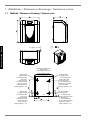
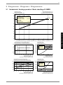
Sole/WasserWärmepumpe für Innenaufstellung Installation and Operating Instructions English Instructions d’installation et d’utilisation Français Montage- und Gebrauchsanweisung Brine-to-Water Heat Pump for Indoor Installation Bestell-Nr. / Order no. / No de commande : 452232.66.14 Deutsch SI 5MER SI 7MER SI 9MER SI 11MER Pompe à chaleur eau glycolée-eau pour installation intérieure FD 8612 Table of contents 1 Please Read Immediately .............................................................................................................E-2 1.1 Important Information.............................................................................................................................. E-2 1.2 Legal Regulations and Directives ........................................................................................................... E-2 1.3 Energy-Efficient Use of the Heat Pump .................................................................................................. E-2 2 Purpose of the Heat Pump ...........................................................................................................E-3 3 Basic Device ..................................................................................................................................E-3 4 Accessories ...................................................................................................................................E-4 4.1 Brine Circuit Manifold.............................................................................................................................. E-4 5 Transport........................................................................................................................................E-4 6 Set-up .............................................................................................................................................E-4 6.1 General Information ................................................................................................................................ E-4 6.2 Acoustic Emissions................................................................................................................................. E-4 7 Installation .....................................................................................................................................E-5 7.1 7.2 7.3 7.4 8 General Information ................................................................................................................................ E-5 Heating System Connection ................................................................................................................... E-5 Heat Source Connection......................................................................................................................... E-5 Electrical Connection .............................................................................................................................. E-5 Commissioning .............................................................................................................................E-6 8.1 General Information ................................................................................................................................ E-6 8.2 Preparation ............................................................................................................................................. E-6 8.3 Start-up Procedure ................................................................................................................................. E-6 9 Maintenance and Cleaning ...........................................................................................................E-7 9.1 Maintenance ........................................................................................................................................... E-7 9.2 Cleaning the Heating System ................................................................................................................. E-7 9.3 Cleaning the Heat Source System.......................................................................................................... E-7 10 Faults / Trouble-Shooting .............................................................................................................E-7 11 Decommissioning / Disposal .......................................................................................................E-7 12 Device Information ........................................................................................................................E-8 Anhang / Appendix / Annexes ............................................................................................................ A-I www.dimplex.de E-1 English 2.1 Application .............................................................................................................................................. E-3 2.2 Operating Principle ................................................................................................................................. E-3 1 1 Please Read Immediately 1.1 Important Information ATTENTION! The heat pump is not secured to the wooden pallet. ATTENTION! The heat pump must not be tilted more than 45° (in any direction). English ATTENTION! Do not use the holes in the panel assemblies for lifting the device! ATTENTION! Flush the heating system prior to connecting the heat pump. ATTENTION! The supplied dirt trap must be inserted in the heat source inlet of the heat pump to protect the evaporator against the ingress of impurities. ATTENTION! The brine solution must contain at least a 25 % concentration of a monoethylene glycol or propylene glycol-based antifreeze, which must be mixed before filling. ATTENTION! The heat pump must be started up in accordance with the installation and operating instructions of the heat pump controller. ATTENTION! We recommend the installation of a suitable corrosion protection system to prevent the formation of deposits (e.g. rust) in the condenser of the heat pump. ATTENTION! Any work on the heat pump may only be performed by authorised and qualified after-sales service technicians. ATTENTION! Disconnect all electrical circuits from the power source prior to opening the device. E-2 1.2 Legal Regulations and Directives This heat pump conforms to all relevant DIN/VDE regulations and EU directives. Refer to the EC Declaration of Conformity in the appendix for details. The heat pump must be connected to the power supply in compliance with all relevant VDE, EN and IEC standards. Any further connection requirements stipulated by local utility companies must also be observed. The heat pump is to be connected to the heat source system and the heating or cooling system in accordance with all applicable regulations. Persons, especially children, who are not capable of operating the device safely due to their physical, sensory or mental abilities or their inexperience or lack of knowledge, must not operate this device without supervision or instruction by the person in charge. Children must be supervised to ensure that they do not play with the device. 1.3 Energy-Efficient Use of the Heat Pump By operating this heat pump you are helping to protect our environment. The heating or cooling system and the heat source must be properly designed and dimensioned to ensure efficient operation. It is particularly important to keep water flow temperatures as low as possible in heating operation. All connected energy consumers should therefore be suitable for low flow temperatures. Raising the heating water temperature by 1 K corresponds to an increase in energy consumption of approx. 2.5 %. Low-temperature heating systems with flow temperatures between 30 °C and 50 °C are well-suited for energy-efficient operation. 3 2.1 Purpose of the Heat Pump Application The brine-to-water heat pump is designed for use in existing or newly built heating systems. Brine is used as the heat carrier in the heat source system. Borehole heat exchangers, ground heat collectors or similar systems can be used as the heat source. 2.2 Operating Principle Heating The heat generated by the sun, wind and rain is stored in the ground. This heat stored in the ground is collected at a low temperature by the brine circulating in the ground collector, ground coil or similar device. A circulating pump then conveys the “heated” brine to the evaporator of the heat pump. There the heat is given off to the refrigerant in the refrigerating cycle. This cools the brine so that it can once again absorb thermal energy in the brine circuit. 3 Basic Device The basic device consists of a ready-to-use heat pump for indoor installation, complete with sheet metal casing, control panel and integrated controller. The refrigerating cycle contains the refrigerant R407C. R407C refrigerant is CFC-free, non-ozone depleting and non-combustible. All components required for the operation of the heat pump are located on the control panel. An external wall temperature sensor including fixing accessories and a dirt trap are supplied with the heat pump. The power feed for the load current and the control current must be installed by the customer. The supply lead of the brine circulating pump (to be provided by the customer) must be connected to the control panel. If required, the supply lead of the brine pump is be equipped with a motor protection device. The customer must provide both the collector and the brine circuit manifold. The refrigerant is drawn in by the electrically driven compressor, compressed and “pumped” to a higher temperature level. The electrical power needed to run the compressor is not lost in this process. Most of it is absorbed by the refrigerant. Subsequently, the refrigerant is passed through the condenser where it transfers its heat energy to the heating water. Depending on the set operating point (thermostat setting), the heating water is thus heated up to a max. of 60 °C. Cooling The functions of the evaporator and the liquifier are reversed in the “Cooling” operating mode. The heating water gives up its heat to the refrigerant via the liquifier which is now functioning as an evaporator. The refrigerant is pumped to a higher temperature level using the compressor. Heat passes into the brine via the liquifier (evaporator in heating operation) and consequently into the ground. www.dimplex.de 1) Liquifier 2) Control panel 3) Evaporator 4) Compressor E-3 English 2 4 4 Accessories 4.1 Brine Circuit Manifold The brine circuit manifold merges the individual collector loops of the heat source system into a single main pipe which is connected to the heat pump. Integrated ball valves allow the individual brine circuits to be shut off for de-aeration purposes. 6 6.1 Set-up General Information The unit may only be installed indoors in rooms with low humidity on a level, smooth and horizontal surface. The entire base of the frame should lie directly on the floor to ensure a good soundproof seal. If this is not the case, additional sound insulation measures may be necessary. English The heat pump must be installed so that maintenance work can be carried out without hindrance. This can be ensured by maintaining a clearance of approx. 1 m in front of and on each side of the heat pump. 5 Transport A lift truck is suited for transporting the unit on a level surface. Carrying straps may be used if the heat pump needs to be transported on an uneven surface or carried up or down stairs. These straps can be passed directly underneath the wooden pallet. ATTENTION! The heat pump is not secured to the wooden pallet. ATTENTION! The heat pump must not be tilted more than 45° (in any direction). Use the holes provided in the sides of the frame to lift the unit without the pallet. The side panel assemblies must be removed for this purpose. Any commercially available length of pipe can be used as a carrying aid. ATTENTION! Do not use the holes in the panel assemblies for lifting the device! E-4 6.2 Acoustic Emissions The heat pump operates silently due to efficient sound insulation. To prevent noise transmission to the foundation, a suitable, sound dampening rubber mat should be placed underneath the base frame of the heat pump. To prevent any sound from being transmitted to the heating system, we recommend connecting the heat pump to the heating system by means of hose sections. 7.4 Installation 7.1 General Information The following connections need to be established on the heat pump: Flow and return flow of the brine system Flow and return flow of the heating system Power supply 7.2 Heating System Connection ATTENTION! Flush the heating system prior to connecting the heat pump. Before connecting the heating water system to the heat pump, the heating system must be flushed to remove any impurities, residue from sealants, etc. Any accumulation of deposits in the liquifier could cause the heat pump to completely break down. Once the heating system has been installed, it must be filled, deaerated and pressure-tested. The sensors which are delivered already connected and loosely placed in the switch box must be mounted and insulated according to the block diagram. 7.3 Heat Source Connection The following procedure must be observed when connecting the heat source: Connect the brine pipe to the heat pump flow and return. The hydraulic plumbing diagram must be adhered to. ATTENTION! The supplied dirt trap must be inserted in the heat source inlet of the heat pump to protect the evaporator against the ingress of impurities. In addition, a micro bubble air separator must be installed in the heat source system. The brine liquid must be produced prior to charging the system. The liquid must have an antifreeze concentration of at least 25 % to ensure frost protection down to -14 °C. Only monoethylene glycol or propylene glycol-based antifreeze may be used. The heat source system must be de-aerated and checked for leaks. ATTENTION! The brine solution must contain at least a 25 % concentration of a monoethylene glycol or propylene glycol-based antifreeze, which must be mixed before filling. Minimum heating water flow rate 7.4 The minimum heating water flow rate through the heat pump must be assured in all operating states of the heating system. This can be accomplished, for example, by installing either a manifold without differential pressure or an overflow valve. The procedure for adjusting an overflow valve is described in the Chapter Start-Up. The following electrical connections must be established on the heat pump: Antifreeze protection for installation locations prone to frost The antifreeze function of the heat pump controller is active whenever the controller and the heat circulating pumps are ready for operation. If the heat pump is taken out of service or in the event of a power failure, the system has to be drained. The heating circuit should be operated with a suitable antifreeze if heat pump systems are implemented in buildings where a power failure can not be detected (holiday home). Electrical Connection Connection of the control line to the control panel of the heat pump via terminal X1: L/N/PE. Connection of the mains cable to the control panel of the heat pump via terminal X6: L/N/PE. Connection of the brine circulating pump (to be provided by the customer) to the control panel of the heat pump via terminal X1: PE and pump contactor K5: 14/24. As an option, the brine pump can also be directly connected (see terminal connection plan). All electrical components required for the operation of the heat pump are located on the control panel. For detailed instructions concerning the connection and functioning of the heat pump controller (e.g. external wall sensor included in the scope of supply) refer to the operating manual supplied with the controller. A disconnecting device with a contact gap of at least 3 mm (e.g. utility blocking contactor or power contactor) as well as a 1-pole circuit breaker have to be provided by the customer. The required conductor cross-section is to be selected according to the power consumption of the heat pump, the technical connection requirements of the respective utility company as well as all applicable regulations. Details on the power consumption of the heat pump are listed on both the product information sheet and the type plate. The connection terminals are designed for a max. conductor cross-section of 10mm2. www.dimplex.de E-5 English 7 8 8 Commissioning 8.3 Start-up Procedure The heat pump is started up via the heat pump controller. 8.1 General Information To ensure that start-up is performed correctly, it should only be carried out by an after-sales service technician authorised by the manufacturer. This may be a condition for extending the guarantee (see Warranty).Start-up should be carried out in heating operation. 8.2 Preparation English The following items need to be checked prior to start-up: The heat pump must be fully connected, as described in Chapter 7. The heat source system and the heating circuit must have been filled and checked. The dirt trap must be inserted in the brine inlet of the heat pump. All valves that could impair proper flow in the brine and heating circuits must be open. The heat pump controller must be adapted to the heating system in accordance with the controller’s operating instructions. ATTENTION! The heat pump must be started up in accordance with the installation and operating instructions of the heat pump controller. If an overflow valve is fitted to assure the minimum heating water flow rate, the valve must be set in accordance with the requirements of the respective heating system. Incorrect adjustment can lead to faulty operation and increased energy consumption. We recommend carrying out the following procedure to correctly adjust the overflow valve: Close all of the heating circuits that may also be closed during operation (depending on the type of heat pump usage) so that the most unfavourable operating state - with respect to the water flow rate - is achieved. This normally means the heating circuits of the rooms on the south and west sides of the building. At least one heating circuit must remain open (e.g. bathroom). The overflow valve should be opened far enough to produce the maximum temperature spread between the heating flow and return flow listed in the table below for the current heat source temperature. The temperature spread should be measured as close as possible to the heat pump. The heating element of mono energy systems should be disconnected. Heat source temperature Max. temperature spread between heating flow and return flow From To -5° C 0° C 10 K 1° C 5° C 11 K 6° C 9° C 12 K 10° C 14° C 13 K 15° C 20° C 14 K 21° C 25° C 15 K Any faults occurring during operation are displayed on the heat pump controller and can be corrected as described in the operating manual of the heat pump controller. E-6 11 Maintenance and Cleaning 9.1 Maintenance The heat pump is maintenance-free. To prevent faults due to sediment in the heat exchangers, care must be taken to ensure that no impurities can enter either the heat source system or the heating system. In the event that operating malfunctions due to contamination occur nevertheless, the system should be cleaned as described below. 9.2 Cleaning the Heating System The ingress of oxygen into the heating water circuit may result in the formation of oxidation products (rust), particularly if steel components are used. This oxygen enters the heating system via the valves, the circulating pumps and/or plastic pipes. It is therefore essential - in particular with respect to the piping of underfloor heating systems - that only diffusion-proof materials are used. ATTENTION! We recommend the installation of a suitable corrosion protection system to prevent the formation of deposits (e.g. rust) in the condenser of the heat pump. Residue from lubricants and sealants may also contaminate the heating water. In the case of severe contamination leading to a reduction in the performance of the liquifier in the heat pump, the system must be cleaned by a heating technician. 10 Faults / TroubleShooting This heat pump is a quality product and is designed for troublefree operation. In the event that a fault should occur, it will be indicated on the heat pump manager display. Simply consult the Faults and Trouble-Shooting page in the operating instructions of the heat pump controller. If you cannot correct the fault yourself, please contact your aftersales service technician. ATTENTION! Any work on the heat pump may only be performed by authorised and qualified after-sales service technicians. ATTENTION! Disconnect all electrical circuits from the power source prior to opening the device. 11 Decommissioning / Disposal Before removing the heat pump, disconnect it from the power source and close all valves. Observe all environmentally-relevant requirements regarding the recovery, recycling and disposal of materials and components in accordance with all applicable standards. Particular attention should be paid to the proper disposal of refrigerants and refrigeration oils. According to today’s state of knowledge, we recommend using a 5 % phosphoric acid solution for cleaning purposes. However, if cleaning needs to be performed more frequently, a 5 % formic acid solution should be used. In either case, the cleaning fluid should be at room temperature. We recommend flushing the heat exchanger in the direction opposite to the normal flow direction. To prevent acidic cleaning agents from entering the heating system circuit, we recommend connecting the flushing device directly to the flow and return flow of the liquifier. It is important that the system be thoroughly flushed using appropriate neutralising agents to prevent any damage from being caused by cleaning agent residue remaining in the system. Acids must be used with great care and all relevant regulations of the employers’ liability insurance associations must be adhered to. If in doubt, contact the manufacturer of the chemicals! 9.3 Cleaning the Heat Source System ATTENTION! The supplied dirt trap must be inserted in the heat source inlet of the heat pump to protect the evaporator against the ingress of impurities. Clean the dirt trap’s filter screen one day after start-up and subsequently in weekly intervals. If no more signs of contamination are evident, the filter can be removed to reduce pressure drops. www.dimplex.de E-7 English 9 12 12 Device Information 1 Type and order code 2 Design 2.1 Model 2.2 Degree of protection according to EN 60 529 2.3 Installation location 3 Performance data 3.1 Operating temperature limits: SI 11MER Reversible Reversible Reversible Reversible IP20 IP20 IP20 IP20 Indoors Indoors Indoors Indoors English Up to 55 Up to 55 Up to 55 Up to 55 Cooling, flow °C +7 to +20 +7 to +20 +7 to +20 +7 to +20 Brine (heat source, heating) °C -5 to +25 -5 to +25 -5 to +25 -5 to +25 Brine (heat sink, cooling) °C +5 to +25 +5 to +25 +5 to +25 +5 to +25 Monoethylene glycol Monoethylene glycol Monoethylene glycol Monoethylene glycol 25% 25% 25% 25% 9.4 9.1 10.6 9.9 Minimum brine concentration (-13 °C freezing temperature) Heat output / COP 3.4 SI 9MER °C Temperature spread of heating water (flow/return flow) at B0 / W35K 3.3 SI 7MER Heating water flow Antifreeze 3.2 SI 5MER kW / --- 4.0 / 2.0 5.4 / 2.1 7.5 / 2.0 9.8 / 2.1 at B0 / W50 1 kW / --- 4.8 / 2.7 6.2 / 2.7 8.8 / 2.8 11.3 / 2.9 at B0 / W35 1 kW / --- 4.9 / 3.9 6.4 / 3.8 9.3 / 4.0 11.6 / 4.1 at B20 / W8 kW / --- 5.4 / 4.6 7.0 / 4.5 9.9 / 4.6 11.4 / 4.6 at B20 / W18 kW / --- 6.6 / 5.3 8.6 / 5.3 12.0 / 5.4 14.1 / 5.3 at B10 / W8 kW / --- 5.4 / 5.6 7.0 / 5.5 9.9 / 5.6 11.6 / 5.7 at B10 / W18 kW / --- 6.8 / 6.7 8.8 / 6.6 12.4 / 6.7 14.1 / 6.5 at B-5 / W55 Cooling capacity / COP 1 3.5 Sound power level 54 55 56 56 3.6 Heating water flow with an internal pressure differential of m³/h / Pa dB(A) 0.45 / 1,900 0.6 / 3,300 0.75 / 2,300 1.0 / 4,100 3.7 Brine throughput with an internal pressure differential (heat source) of m³/h / Pa 1.2 / 16,000 1.7 / 29,500 2.3 / 25,000 3.0 / 24,000 3.8 Refrigerant; total filling weight type / kg R407C / 0.9 R407C / 0.9 R407C / 1.25 R407C / 1.6 4 Dimensions, connections and weight 4.1 Device dimensions without connections 2 H x W x L mm 4.2 Device connections to heating system Inch G 1¼" external G 1¼" external G 1¼" external G 1¼" external 4.3 Device connections to heat source Inch G 1¼" external G 1¼" external G 1¼" external G 1¼" external 4.4 Weight of the transportable unit(s) incl. packing kg 115 117 124 128 5 Electrical Connection 5.1 Nominal voltage; fuse protection 230 / 16 230 / 16 230 / 20 230 / 25 1.25 1.68 2.3 2.8 24 26 38 38 6.8 / 0.8 9.1 / 0.8 12.5 / 0.8 15.2 / 0.8 3 3 3 3 Yes Yes Yes Yes 1 V/A 5.2 Nominal power consumption 5.3 Starting current with soft starter A 5.4 Nominal current B0 W35 / cos ϕ A / --- 6 Complies with the European safety regulations 7 Additional model features 7.1 Water in device protected against freezing 4 7.2 Performance levels 7.3 Controller internal/external B0 W35 kW 805 × 650 × 462 805 × 650 × 462 805 × 650 × 462 805 × 650 × 462 1 1 1 1 Internal Internal Internal Internal 1. This data indicates the size and capacity of the system. For an analysis of the economic and energy efficiency of the system, both the bivalence point and the regulation should also be taken into consideration. The specified values, e.g. B10 / W55, have the following meaning: Heat source temperature 10 °C and heating water flow temperature 55 °C. 2. Note that additional space is required for pipe connections, operation and maintenance. 3. See CE declaration of conformity 4. The heat circulating pump and the heat pump controller must always be ready for operation. E-8 Anhang / Appendix / Annexes 1 Maßbilder / Dimension Drawings / Schémas cotés................................................................... A-II 1.1 Maßbild / Dimension Drawing / Schéma coté......................................................................................... A-II 2 Diagramme / Diagrams / Diagrammes....................................................................................... A-III 2.1 2.2 2.3 2.4 2.5 2.6 2.7 2.8 3 Heizbetrieb / Heating operation / Mode chauffage SI 5MER ................................................................. A-III Kühlbetrieb / Cooling operation / Mode refroidissement SI 5MER ........................................................A-IV Heizbetrieb / Heating operation / Mode chauffage SI 7MER ..................................................................A-V Kühlbetrieb / Cooling operation / Mode refroidissement SI 7MER ........................................................A-VI Heizbetrieb / Heating operation / Mode chauffage SI 9MER ................................................................A-VII Kühlbetrieb / Cooling operation / Mode refroidissement SI 9MER ......................................................A-VIII Heizbetrieb / Heating operation / Mode chauffage SI 11MER ...............................................................A-IX Kühlbetrieb / Cooling operation / Mode refroidissement SI 11MER .......................................................A-X Stromlaufpläne / Circuit Diagrams / Schémas électriques...................................................... A-XI Steuerung Standardregler / Control via the standard controller / Commande régulateur standard.......A-XI Steuerung Kühlregler / Control via the cooling controller / Commande régulateur refroidissement .....A-XII Last / Load / Charge ............................................................................................................................A-XIII Anschlussplan Standardregler / Terminal diagram for standard controller / Schéma de branchement du régulateur standard............................................................................................................................. A-XIV 3.5 Anschlussplan Kühlregler / Terminal diagram for cooling controller / Schéma de branchement du régulateur de refroidissement .............................................................................................................. A-XV 3.6 Legende / Legend / Légende.............................................................................................................. A-XVI 4 Hydraulisches Prinzipschema / Hydraulic Plumbing Diagram / Schéma hydraulique ......A-XVII 4.1 Darstellung / Schematic View / Représentation................................................................................. A-XVII 4.2 Legende / Legend / Légende............................................................................................................ A-XVIII 5 Konformitätserklärung / Declaration of Conformity / Déclaration de conformité ...............A-XIX A-I Anhang · Appendix · Annexes 3.1 3.2 3.3 3.4 1 1 Maßbilder / Dimension Drawings / Schémas cotés 1.1 Maßbild / Dimension Drawing / Schéma coté Anhang · Appendix · Annexes FDDSSUR[HQY =XIKUXQJ(OHNWUROHLWXQJHQ 6XSSO\FDEOHV $PHQpHOLJQHVpOHFWULTXHV :lUPHTXHOOH (LQJDQJLQ:3 ´$XHQJHZLQGH +HL]XQJVYRUODXI $XVJDQJDXV:3 ´$XHQJHZLQGH +HDWVRXUFH +HDWSXPSLQOHW ´H[WHUQDOWKUHDG +HDWLQJZDWHUIORZ +HDWSXPSRXWOHW ´H[WHUQDOWKUHDG 6RXUFHGHFKDOHXU (QWUpHGDQVOD3$& )LOHWDJHH[WpULHXU´ A-II $OOHUHDXGHFKDXIIDJH 6RUWLHGHOD3$& )LOHWDJHH[WpULHXU´ :lUPHTXHOOH $XVJDQJDXV:3 ´$XHQJHZLQGH +HL]XQJVUFNODXI (LQJDQJLQ:3 ´$XHQJHZLQGH +HDWVRXUFH +HDWSXPSRXWOHW ´H[WHUQDOWKUHDG +HDWLQJZDWHUUHWXUQIORZ +HDWSXPSLQOHW ´H[WHUQDOWKUHDG 6RXUFHGHFKDOHXU 6RUWLHGHOD3$& )LOHWDJHH[WpULHXU´ 5HWRXUHDXGHFKDXIIDJH (QWUpHGDQVOD3$& )LOHWDJHH[WpULHXU´ 2.1 2 Diagramme / Diagrams / Diagrammes Heizbetrieb / Heating operation / Mode chauffage SI 5MER +HL]OHLVWXQJLQ>N:@ +HDWLQJFDSDFLW\LQ>N:@ 3XLVVDQFHGHFKDXIIDJHHQ>N:@ :DVVHUDXVWULWWVWHPSHUDWXULQ>&@ :DWHURXWOHWWHPSHUDWXUHLQ>&@ 7HPSpUDWXUHGHVRUWLHGHO HDXHQ>&@ %HGLQJXQJHQÂ&RQGLWLRQVÂ&RQGLWLRQV +HL]ZDVVHUGXUFKVDW] +HDWLQJZDWHUIORZUDWH 'pELWG HDXGHFKDXIIDJH 6ROHGXUFKVDW] %ULQHIORZUDWH 'pELWG HDXJO\FROpH P K PK Anhang · Appendix · Annexes 2.1 6ROHHLQWULWWVWHPSHUDWXULQ>&@Â%ULQHLQOHWWHPSHUDWXUHLQ>&@Â7HPSpUDWXUHG HQWUpHG HDXJO\FROpHHQ>&@ /HLVWXQJVDXIQDKPHLQFO3XPSHQOHLVWXQJVDQWHLO 3RZHUFRQVXPSWLRQLQFOSRZHULQSXWWRSXPS &RQVRPPDWLRQGHSXLVVDQFH\FRPSULVSDUWGHFRQVRPPDWLRQGHODSRPSH 'UXFNYHUOXVWLQ>3D@ 3UHVVXUHORVVLQ>3D@ 3HUWHGHSUHVVLRQHQ>3D@ 9HUGDPSHU (YDSRUDWRU (YDSRUDWHXU /HLVWXQJV]DKOLQFO3XPSHQOHLVWXQJVDQWHLO &RHIILFLHQWRISHUIRUPDQFHLQFOSRZHULQSXWWRSXPS &RHIILFLHQWGHSHUIRUPDQFH\FRPSULVSDUWGHFRQVRPPDWLRQGHODSRPSH 'UXFNYHUOXVWLQ>3D@ 3UHVVXUHORVVLQ>3D@ 3HUWHGHSUHVVLRQHQ>3D@ 9HUIOVVLJHU &RQGHQVHU &RQGHQVHXU 6ROHGXUFKIOXVVLQ>PK@ %ULQHIORZUDWHLQ>PK@ 'pELWG HDXJO\FROpHHQ>PK@ 6ROHHLQWULWWVWHPSHUDWXULQ>&@ %ULQHLQOHWWHPSHUDWXUHLQ>&@ 7HPSpUDWXUHG HQWUpHG¶HDXJO\FROpHHQ>&@ 6ROHHLQWULWWVWHPSHUDWXULQ>&@ %ULQHLQOHWWHPSHUDWXUHLQ>&@ 7HPSpUDWXUHG HQWUpHG¶HDXJO\FROpHHQ>&@ +HL]ZDVVHUGXUFKIOXVVLQ>PK@ +HDWLQJZDWHUIORZUDWHLQ>PK@ 'pELWG HDXGHFKDXIIDJHHQ>PK@ A-III 2.2 2.2 Kühlbetrieb / Cooling operation / Mode refroidissement SI 5MER .KOOHLVWXQJLQ>N:@ &RROLQJFDSDFLW\LQ>N:@ 3XLVVDQFHGHUHIURLGLVVHPHQWHQ>N:@ :DVVHUDXVWULWWVWHPSHUDWXULQ>&@ :DWHURXWOHWWHPSHUDWXUHLQ>&@ 7HPSpUDWXUHGHVRUWLHGHO HDXHQ>&@ %HGLQJXQJHQÂ&RQGLWLRQVÂ&RQGLWLRQV :DVVHUGXUFKVDW] :DWHUIORZUDWH 'pELWG HDX 6ROHGXUFKVDW] %ULQHIORZUDWH 'pELWG HDXJO\FROpH PK PK Anhang · Appendix · Annexes 6ROHHLQWULWWVWHPSHUDWXULQ>&@Â%ULQHLQOHWWHPSHUDWXUHLQ>&@Â7HPSpUDWXUHG HQWUpHG HDXJO\FROpHHQ>&@ /HLVWXQJVDXIQDKPHLQFO3XPSHQOHLVWXQJVDQWHLO 3RZHUFRQVXPSWLRQLQFOSRZHULQSXWWRSXPS &RQVRPPDWLRQGHSXLVVDQFH\FRPSULVSDUWGHFRQVRPPDWLRQGHODSRPSH 'UXFNYHUOXVWLQ>3D@ 3UHVVXUHORVVLQ>3D@ 3HUWHGHSUHVVLRQHQ>3D@ 9HUGDPSHU (YDSRUDWRU (YDSRUDWHXU /HLVWXQJV]DKOLQFO3XPSHQOHLVWXQJVDQWHLO &RHIILFLHQWRISHUIRUPDQFHLQFOSRZHULQSXWWRSXPS &RHIILFLHQWGHSHUIRUPDQFH\FRPSULVSDUWGHFRQVRPPDWLRQGHODSRPSH 6ROHHLQWULWWVWHPSHUDWXULQ>&@ %ULQHLQOHWWHPSHUDWXUHLQ>&@ 7HPSpUDWXUHG HQWUpHG¶HDXJO\FROpHHQ>&@ A-IV 9HUIOVVLJHU &RQGHQVHU &RQGHQVHXU 'UXFNYHUOXVWLQ>3D@ 3UHVVXUHORVVLQ>3D@ 3HUWHGHSUHVVLRQHQ>3D@ 6ROHGXUFKIOXVVLQ>PK@ %ULQHIORZUDWHLQ>PK@ 'pELWG HDXJO\FROpHHQ>PK@ 6ROHHLQWULWWVWHPSHUDWXULQ>&@ %ULQHLQOHWWHPSHUDWXUHLQ>&@ 7HPSpUDWXUHG HQWUpHG¶HDXJO\FROpHHQ>&@ +HL]ZDVVHUGXUFKIOXVVLQ>PK@ +HDWLQJZDWHUIORZUDWHLQ>PK@ 'pELWG HDXGHFKDXIIDJHHQ>PK@ 2.3 Heizbetrieb / Heating operation / Mode chauffage SI 7MER +HL]OHLVWXQJLQ>N:@ +HDWLQJFDSDFLW\LQ>N:@ 3XLVVDQFHGHFKDXIIDJHHQ>N:@ :DVVHUDXVWULWWVWHPSHUDWXULQ>&@ :DWHURXWOHWWHPSHUDWXUHLQ>&@ 7HPSpUDWXUHGHVRUWLHGHO HDXHQ>&@ %HGLQJXQJHQÂ&RQGLWLRQVÂ&RQGLWLRQV +HL]ZDVVHUGXUFKVDW] +HDWLQJZDWHUIORZUDWH 'pELWG HDXGHFKDXIIDJH P K 6ROHGXUFKVDW] %ULQHIORZUDWH 'pELWG HDXJO\FROpH PK Anhang · Appendix · Annexes 2.3 6ROHHLQWULWWVWHPSHUDWXULQ>&@Â%ULQHLQOHWWHPSHUDWXUHLQ>&@Â7HPSpUDWXUHG HQWUpHG HDXJO\FROpHHQ>&@ /HLVWXQJVDXIQDKPHLQFO3XPSHQOHLVWXQJVDQWHLO 3RZHUFRQVXPSWLRQLQFOSRZHULQSXWWRSXPS &RQVRPPDWLRQGHSXLVVDQFH\FRPSULVSDUWGHFRQVRPPDWLRQGHODSRPSH 'UXFNYHUOXVWLQ>3D@ 3UHVVXUHORVVLQ>3D@ 3HUWHGHSUHVVLRQHQ>3D@ 9HUGDPSHU (YDSRUDWRU (YDSRUDWHXU /HLVWXQJV]DKOLQFO3XPSHQOHLVWXQJVDQWHLO &RHIILFLHQWRISHUIRUPDQFHLQFOSRZHULQSXWWRSXPS &RHIILFLHQWGHSHUIRUPDQFH\FRPSULVSDUWGHFRQVRPPDWLRQGHODSRPSH 'UXFNYHUOXVWLQ>3D@ 3UHVVXUHORVVLQ>3D@ 3HUWHGHSUHVVLRQHQ>3D@ 9HUIOVVLJHU &RQGHQVHU &RQGHQVHXU 6ROHGXUFKIOXVVLQ>PK@ %ULQHIORZUDWHLQ>PK@ 'pELWG HDXJO\FROpHHQ>PK@ 6ROHHLQWULWWVWHPSHUDWXULQ>&@ %ULQHLQOHWWHPSHUDWXUHLQ>&@ 7HPSpUDWXUHG HQWUpHG¶HDXJO\FROpHHQ>&@ 6ROHHLQWULWWVWHPSHUDWXULQ>&@ %ULQHLQOHWWHPSHUDWXUHLQ>&@ 7HPSpUDWXUHG HQWUpHG¶HDXJO\FROpHHQ>&@ +HL]ZDVVHUGXUFKIOXVVLQ>PK@ +HDWLQJZDWHUIORZUDWHLQ>PK@ 'pELWG HDXGHFKDXIIDJHHQ>PK@ A-V 2.4 2.4 Kühlbetrieb / Cooling operation / Mode refroidissement SI 7MER .KOOHLVWXQJLQ>N:@ &RROLQJFDSDFLW\LQ>N:@ 3XLVVDQFHGHUHIURLGLVVHPHQWHQ>N:@ :DVVHUDXVWULWWVWHPSHUDWXULQ>&@ :DWHURXWOHWWHPSHUDWXUHLQ>&@ 7HPSpUDWXUHGHVRUWLHGHO HDXHQ>&@ %HGLQJXQJHQÂ&RQGLWLRQVÂ&RQGLWLRQV :DVVHUGXUFKVDW] :DWHUIORZUDWH 'pELWG HDX PK 6ROHGXUFKVDW] %ULQHIORZUDWH 'pELWG HDXJO\FROpH PK Anhang · Appendix · Annexes 6ROHHLQWULWWVWHPSHUDWXULQ>&@Â%ULQHLQOHWWHPSHUDWXUHLQ>&@Â7HPSpUDWXUHG HQWUpHG HDXJO\FROpHHQ>&@ /HLVWXQJVDXIQDKPHLQFO3XPSHQOHLVWXQJVDQWHLO 3RZHUFRQVXPSWLRQLQFOSRZHULQSXWWRSXPS &RQVRPPDWLRQGHSXLVVDQFH\FRPSULVSDUWGHFRQVRPPDWLRQGHODSRPSH 'UXFNYHUOXVWLQ>3D@ 3UHVVXUHORVVLQ>3D@ 3HUWHGHSUHVVLRQHQ>3D@ 9HUGDPSHU (YDSRUDWRU (YDSRUDWHXU 9HUIOVVLJHU &RQGHQVHU &RQGHQVHXU 'UXFNYHUOXVWLQ>3D@ 3UHVVXUHORVVLQ>3D@ 3HUWHGHSUHVVLRQHQ>3D@ 6ROHGXUFKIOXVVLQ>PK@ %ULQHIORZUDWHLQ>PK@ 'pELWG HDXJO\FROpHHQ>PK@ 6ROHHLQWULWWVWHPSHUDWXULQ>&@ %ULQHLQOHWWHPSHUDWXUHLQ>&@ 7HPSpUDWXUHG HQWUpHG¶HDXJO\FROpHHQ>&@ /HLVWXQJV]DKOLQFO3XPSHQOHLVWXQJVDQWHLO &RHIILFLHQWRISHUIRUPDQFHLQFOSRZHULQSXWWRSXPS &RHIILFLHQWGHSHUIRUPDQFH\FRPSULVSDUWGHFRQVRPPDWLRQGHODSRPSH 6ROHHLQWULWWVWHPSHUDWXULQ>&@ %ULQHLQOHWWHPSHUDWXUHLQ>&@ 7HPSpUDWXUHG HQWUpHG¶HDXJO\FROpHHQ>&@ A-VI +HL]ZDVVHUGXUFKIOXVVLQ>PK@ +HDWLQJZDWHUIORZUDWHLQ>PK@ 'pELWG HDXGHFKDXIIDJHHQ>PK@ 2.5 Heizbetrieb / Heating operation / Mode chauffage SI 9MER +HL]OHLVWXQJLQ>N:@ +HDWLQJFDSDFLW\LQ>N:@ 3XLVVDQFHGHFKDXIIDJHHQ>N:@ :DVVHUDXVWULWWVWHPSHUDWXULQ>&@ :DWHURXWOHWWHPSHUDWXUHLQ>&@ 7HPSpUDWXUHGHVRUWLHGHO HDXHQ>&@ %HGLQJXQJHQÂ&RQGLWLRQVÂ&RQGLWLRQV +HL]ZDVVHUGXUFKVDW] +HDWLQJZDWHUIORZUDWH 'pELWG HDXGHFKDXIIDJH P K 6ROHGXUFKVDW] %ULQHIORZUDWH 'pELWG HDXJO\FROpH PK Anhang · Appendix · Annexes 2.5 6ROHHLQWULWWVWHPSHUDWXULQ>&@Â%ULQHLQOHWWHPSHUDWXUHLQ>&@Â7HPSpUDWXUHG HQWUpHG HDXJO\FROpHHQ>&@ /HLVWXQJVDXIQDKPHLQFO3XPSHQOHLVWXQJVDQWHLO 3RZHUFRQVXPSWLRQLQFOSRZHULQSXWWRSXPS &RQVRPPDWLRQGHSXLVVDQFH\FRPSULVSDUWGHFRQVRPPDWLRQGHODSRPSH 'UXFNYHUOXVWLQ>3D@ 3UHVVXUHORVVLQ>3D@ 3HUWHGHSUHVVLRQHQ>3D@ 9HUGDPSHU (YDSRUDWRU (YDSRUDWHXU /HLVWXQJV]DKOLQFO3XPSHQOHLVWXQJVDQWHLO &RHIILFLHQWRISHUIRUPDQFHLQFOSRZHULQSXWWRSXPS &RHIILFLHQWGHSHUIRUPDQFH\FRPSULVSDUWGHFRQVRPPDWLRQGHODSRPSH 6ROHGXUFKIOXVVLQ>PK@ %ULQHIORZUDWHLQ>P K@ 'pELWG HDXJO\FROpHHQ>PK@ 6ROHHLQWULWWVWHPSHUDWXULQ>&@ %ULQHLQOHWWHPSHUDWXUHLQ>&@ 7HPSpUDWXUHG HQWUpHG¶HDXJO\FROpHHQ>&@ 6ROHHLQWULWWVWHPSHUDWXULQ>&@ %ULQHLQOHWWHPSHUDWXUHLQ>&@ 7HPSpUDWXUHG HQWUpHG¶HDXJO\FROpHHQ>&@ 'UXFNYHUOXVWLQ>3D@ 3UHVVXUHORVVLQ>3D@ 3HUWHGHSUHVVLRQHQ>3D@ 9HUIOVVLJHU &RQGHQVHU &RQGHQVHXU +HL]ZDVVHUGXUFKIOXVVLQ>PK@ +HDWLQJZDWHUIORZUDWHLQ>PK@ 'pELWG HDXGHFKDXIIDJHHQ>PK@ A-VII 2.6 2.6 Kühlbetrieb / Cooling operation / Mode refroidissement SI 9MER .KOOHLVWXQJLQ>N:@ &RROLQJFDSDFLW\LQ>N:@ 3XLVVDQFHGHUHIURLGLVVHPHQWHQ>N:@ :DVVHUDXVWULWWVWHPSHUDWXULQ>&@ :DWHURXWOHWWHPSHUDWXUHLQ>&@ 7HPSpUDWXUHGHVRUWLHGHO HDXHQ>&@ %HGLQJXQJHQÂ&RQGLWLRQVÂ&RQGLWLRQV :DVVHUGXUFKVDW] :DWHUIORZUDWH 'pELWG HDX 6ROHGXUFKVDW] %ULQHIORZUDWH 'pELWG HDXJO\FROpH PK PK Anhang · Appendix · Annexes 6ROHHLQWULWWVWHPSHUDWXULQ>&@Â%ULQHLQOHWWHPSHUDWXUHLQ>&@Â7HPSpUDWXUHG HQWUpHG HDXJO\FROpHHQ>&@ /HLVWXQJVDXIQDKPHLQFO3XPSHQOHLVWXQJVDQWHLO 3RZHUFRQVXPSWLRQLQFOSRZHULQSXWWRSXPS &RQVRPPDWLRQGHSXLVVDQFH\FRPSULVSDUWGHFRQVRPPDWLRQGHODSRPSH 'UXFNYHUOXVWLQ>3D@ 3UHVVXUHORVVLQ>3D@ 3HUWHGHSUHVVLRQHQ>3D@ 9HUGDPSHU (YDSRUDWRU (YDSRUDWHXU 6ROHHLQWULWWVWHPSHUDWXULQ>&@ %ULQHLQOHWWHPSHUDWXUHLQ>&@ 7HPSpUDWXUHG HQWUpHG¶HDXJO\FROpHHQ>&@ A-VIII 6ROHGXUFKIOXVVLQ>PK@ %ULQHIORZUDWHLQ>PK@ 'pELWG HDXJO\FROpHHQ>PK@ 6ROHHLQWULWWVWHPSHUDWXULQ>&@ %ULQHLQOHWWHPSHUDWXUHLQ>&@ 7HPSpUDWXUHG HQWUpHG¶HDXJO\FROpHHQ>&@ /HLVWXQJV]DKOLQFO3XPSHQOHLVWXQJVDQWHLO &RHIILFLHQWRISHUIRUPDQFHLQFOSRZHULQSXWWRSXPS &RHIILFLHQWGHSHUIRUPDQFH\FRPSULVSDUWGHFRQVRPPDWLRQGHODSRPSH 'UXFNYHUOXVWLQ>3D@ 3UHVVXUHORVVLQ>3D@ 3HUWHGHSUHVVLRQHQ>3D@ 9HUIOVVLJHU &RQGHQVHU &RQGHQVHXU +HL]ZDVVHUGXUFKIOXVVLQ>PK@ +HDWLQJZDWHUIORZUDWHLQ>PK@ 'pELWG HDXGHFKDXIIDJHHQ>PK@ 2.7 Heizbetrieb / Heating operation / Mode chauffage SI 11MER +HL]OHLVWXQJLQ>N:@ +HDWLQJFDSDFLW\LQ>N:@ 3XLVVDQFHGHFKDXIIDJHHQ>N:@ :DVVHUDXVWULWWVWHPSHUDWXULQ>&@ :DWHURXWOHWWHPSHUDWXUHLQ>&@ 7HPSpUDWXUHGHVRUWLHGHO HDXHQ>&@ %HGLQJXQJHQÂ&RQGLWLRQVÂ&RQGLWLRQV +HL]ZDVVHUGXUFKVDW] +HDWLQJZDWHUIORZUDWH 'pELWG HDXGHFKDXIIDJH PK 6ROHGXUFKVDW] %ULQHIORZUDWH 'pELWG HDXJO\FROpH PK Anhang · Appendix · Annexes 2.7 /HLVWXQJVDXIQDKPHLQFO3XPSHQOHLVWXQJVDQWHLO 3RZHUFRQVXPSWLRQLQFOSRZHULQSXWWRSXPS &RQVRPPDWLRQGHSXLVVDQFH\FRPSULVSDUWGHFRQVRPPDWLRQGHODSRPSH 'UXFNYHUOXVWLQ>3D@ 3UHVVXUHORVVLQ>3D@ 3HUWHGHSUHVVLRQHQ>3D@ 9HUGDPSHU (YDSRUDWRU (YDSRUDWHXU 6ROHGXUFKIOXVVLQ>PK@ %ULQHIORZUDWHLQ>PK@ 'pELWG HDXJO\FROpHHQ>PK@ 6ROHHLQWULWWVWHPSHUDWXULQ>&@ %ULQHLQOHWWHPSHUDWXUHLQ>&@ 7HPSpUDWXUHG HQWUpHG¶HDXJO\FROpHHQ>&@ 6ROHHLQWULWWVWHPSHUDWXULQ>&@Â%ULQHLQOHWWHPSHUDWXUHLQ>&@Â7HPSpUDWXUHG HQWUpHG HDXJO\FROpHHQ>&@ /HLVWXQJV]DKOLQFO3XPSHQOHLVWXQJVDQWHLO &RHIILFLHQWRISHUIRUPDQFHLQFOSRZHULQSXWWRSXPS &RHIILFLHQWGHSHUIRUPDQFH\FRPSULVSDUWGHFRQVRPPDWLRQGHODSRPSH 6ROHHLQWULWWVWHPSHUDWXULQ>&@ %ULQHLQOHWWHPSHUDWXUHLQ>&@ 7HPSpUDWXUHG HQWUpHG¶HDXJO\FROpHHQ>&@ 'UXFNYHUOXVWLQ>3D@ 3UHVVXUHORVVLQ>3D@ 3HUWHGHSUHVVLRQHQ>3D@ 9HUIOVVLJHU &RQGHQVHU &RQGHQVHXU +HL]ZDVVHUGXUFKIOXVVLQ>PK@ +HDWLQJZDWHUIORZUDWHLQ>PK@ 'pELWG HDXGHFKDXIIDJHHQ>PK@ A-IX 2.8 2.8 Kühlbetrieb / Cooling operation / Mode refroidissement SI 11MER .KOOHLVWXQJLQ>N:@ &RROLQJFDSDFLW\LQ>N:@ 3XLVVDQFHGHUHIURLGLVVHPHQWHQ>N:@ :DVVHUDXVWULWWVWHPSHUDWXULQ>&@ :DWHURXWOHWWHPSHUDWXUHLQ>&@ 7HPSpUDWXUHGHVRUWLHGHO HDXHQ>&@ %HGLQJXQJHQÂ&RQGLWLRQVÂ&RQGLWLRQV :DVVHUGXUFKVDW] :DWHUIORZUDWH 'pELWG HDX PK 6ROHGXUFKVDW] %ULQHIORZUDWH 'pELWG HDXJO\FROpH PK Anhang · Appendix · Annexes 6ROHHLQWULWWVWHPSHUDWXULQ>&@Â%ULQHLQOHWWHPSHUDWXUHLQ>&@Â7HPSpUDWXUHG HQWUpHG HDXJO\FROpHHQ>&@ /HLVWXQJVDXIQDKPHLQFO3XPSHQOHLVWXQJVDQWHLO 3RZHUFRQVXPSWLRQLQFOSRZHULQSXWWRSXPS &RQVRPPDWLRQGHSXLVVDQFH\FRPSULVSDUWGHFRQVRPPDWLRQGHODSRPSH 'UXFNYHUOXVWLQ>3D@ 3UHVVXUHORVVLQ>3D@ 3HUWHGHSUHVVLRQHQ>3D@ 9HUGDPSHU (YDSRUDWRU (YDSRUDWHXU 6ROHHLQWULWWVWHPSHUDWXULQ>&@ %ULQHLQOHWWHPSHUDWXUHLQ>&@ 7HPSpUDWXUHG HQWUpHG¶HDXJO\FROpHHQ>&@ A-X 6ROHGXUFKIOXVVLQ>PK@ %ULQHIORZUDWHLQ>PK@ 'pELWG HDXJO\FROpHHQ>PK@ 6ROHHLQWULWWVWHPSHUDWXULQ>&@ %ULQHLQOHWWHPSHUDWXUHLQ>&@ 7HPSpUDWXUHG HQWUpHG¶HDXJO\FROpHHQ>&@ /HLVWXQJV]DKOLQFO3XPSHQOHLVWXQJVDQWHLO &RHIILFLHQWRISHUIRUPDQFHLQFOSRZHULQSXWWRSXPS &RHIILFLHQWGHSHUIRUPDQFH\FRPSULVSDUWGHFRQVRPPDWLRQGHODSRPSH 'UXFNYHUOXVWLQ>3D@ 3UHVVXUHORVVLQ>3D@ 3HUWHGHSUHVVLRQHQ>3D@ 9HUIOVVLJHU &RQGHQVHU &RQGHQVHXU +HL]ZDVVHUGXUFKIOXVVLQ>PK@ +HDWLQJZDWHUIORZUDWHLQ>PK@ 'pELWG HDXGHFKDXIIDJHHQ>PK@ 3.1 3 Stromlaufpläne / Circuit Diagrams / Schémas électriques Anhang · Appendix · Annexes Steuerung Standardregler / Control via the standard controller / Commande régulateur standard 1HW]0DLQV5pVHDX 3.1 A-XI 3.2 3.2 Steuerung Kühlregler / Control via the cooling controller / Commande régulateur refroidissement :HJH8PVFKDOWYHQWLO )RXUZD\UHYHUVLQJYDOYH 6RXSDSHGHFRPPXWDWLRQYRLHV Anhang · Appendix · Annexes A-XII Anhang · Appendix · Annexes 3.3 1HW]0DLQV5pVHDX 3.3 Last / Load / Charge A-XIII 3.4 3.4 Anhang · Appendix · Annexes 1HW]/DVW0DLQV/RDG5pVHDX&KDUJH +HL]VWDE ,PPHUVLRQKHDWHU &DUWRXFKHFKDXIIDQWH A-XIV RGHUÂRUÂRX 1HW]0DLQV5pVHDX Anschlussplan Standardregler / Terminal diagram for standard controller / Schéma de branchement du régulateur standard )HXFKWH +XPLGLW\ +XPLGLWp )HXFKWH +XPLGLW\ +XPLGLWp Anhang · Appendix · Annexes 7HPSHU 7HPS 7HPS 7HPSHU 7HPS 7HPS PD[6HQVRUHQ 0D[VHQVRUV FDSWHXUVPD[LPXP 3.5 H[WHUQ H[WHUQDO H[WHUQH 3.5 Anschlussplan Kühlregler / Terminal diagram for cooling controller / Schéma de branchement du régulateur de refroidissement A-XV 3.6 3.6 A1 Legende / Legend / Légende F4 F5 H5 J1...J18 Drahtbrücke, muss eingelegt werden, wenn kein Sperrschütz vorhanden ist Drahtbrücke, muss bei Verwendung des 2ten Sperreinganges entfernt werden Drahtbrücke, muss bei Einsatz eines Motorschutzkontaktes, für die Primärpumpe, entfernt werden Drahtbrücke, muss bei Einsatz eines Motorschutzkontaktes, für den Verdichter, entfernt werden Offene Drahtbrücken oder Kontakte bedeuten Sperre oder Störung Pressostat Niederdruck Sole Thermostat Warmwasser Thermostat Schwimmbadwasser Betriebskondensator Verdichter Elekt. Tauchheizkörper-Warmwasser 2. Wärmeerzeuger (Heizkessel oder Elekt. Heizstab) Lastsicherung für N1-Relaisausgänge an J13 4,0 ATr Lastsicherung für Relaisausgänge an J15 bis J18 am N1 und J12 am N2 4,0 ATr Pressostat Hochdruck Pressostat Niederdruck Leuchte Störfernanzeige Klemmensteckverbinder an N1 (Heizregler) J1...J15 Klemmensteckverbinder an N2 (Kühlregler) Terminal connector at N2 (cooling controller) K5 K20* K21* K22* K23* K25 M1 M11* M13* M14* M15* M16* M18* M19* M21* M22* N1 N2 N3/N4* Schütz Primärpumpe (M11) Schütz für E10 Schütz für E9 EVU Sperrschütz SPR Hilfsrelais Startrelais für N7 Verdichter Primärpumpe Heizungsumwälzpumpe Hauptkreis Heizungsumwälzpumpe 1. Heizkreis Heizungsumwälzpumpe 2. Heizkreis Zusatzumwälzpumpe Warmwasserumwälzpumpe Schwimmbadwasserumwälzpumpe Mischer Hauptkreis Mischer 2. Heizkreis Heizregler Kühlregler Raumstationen für die Taupunktregelung Contactor, primary pump (M11) Contactor for E10 Contactor for E9 Utility blocking contactor SPR auxiliary relay Start relay for N7 Compressor Primary pump Heat circulating pump of the main circuit Heat circulating pump of heating circuit 1 Heat circulating pump of heating circuit 2 Auxiliary circulating pump Hot water circulating pump Swimming pool water circulating pump Mixer for main circuit Mixer for heating circuit 2 Heating controller Cooling controller Room stations for dew point regulation N5* N7 N9* N14 R1* R2 R3* Y1 Taupunktwächter Sanftanlaufsteuerung Raumthermostat Bedienteil Außenfühler Rücklauffühler Warmwasserfühler (alternativ zum Warmwasserthermostat) Fühler für 2ten Heizkreis Eingefrierschutzfühler (Sole) Kodierwiderstand 19k6 Frostschutzfühler Kühlen Frostschutzfühler Heizen Sensoren von N5 Sicherheitstrenntransformator 230/24 VAC-50VA Klemmenleiste Netz-Steuerung L/N/PE-230VAC50Hz/Sicherungen/N- und PE-Verteiler Klemmenleiste 24 VAC-Verteiler Klemmenleiste GND-Verteiler für Sensoren Klemmenleiste Verdichter Klemmenleiste 0 VAC-Verteiler Klemmenleiste Leistungseinspeisung L/N/PE230VAC-50Hz Vier-Wege-Umschaltventil Dew point monitor Soft start control Room thermostat Operating element External sensor Return flow sensor Hot water sensor (as an alternative to the hot water thermostat) Sensor for heating circuit 2 Flow temperature limit sensor (brine) Coding resistor 19.6 kOhm Flow sensor, cooling Flow sensor, heating Sensors from N5 Safety isolating transformer 230/24 V AC-50 VA Terminal strip for mains control L/N/PE-230 V AC 50 Hz/fuses/N and PE terminal block Terminal strip for 24 V AC terminal block Terminal strip for GND terminal block for sensors Terminal strip for compressor Terminal strip for 0 V AC terminal block Terminal strip for power supply L/N/PE-230 V AC 50 Hz Four-way valve Le cavalier à fil doit être inséré en absence de disjoncteur de blocage du fournisseur d'énergie. Cavalier à fil à retirer si la 2e entrée de coupure est utilisée Retirer le cavalier à fil si utilisation d’un contact de disjoncteur de moteur, pour la pompe primaire Retirer le cavalier à fil si utilisation d’un contact de disjoncteur de moteur, pour le compresseur Cavaliers à fil ou contacts ouverts signifient coupure ou panne Pressostat eau glycolée basse pression Thermostat eau chaude Thermostat eau de piscine Condensateur de service - compresseur Thermoplongeur électr. eau chaude 2e générateur de chaleur (chaudière ou cartouche chauffante électrique) Coupe-circuit de la charge pour sorties de relais N1 sur J13 4,0 ATr Coupe-circuit de charge pour sorties de relais en J15 jusqu’à J18 pour N1 et en J12 pour N2 4,0 ATr Pressostat haute pression Pressostat basse pression Témoin de télédétection de pannes Connecteur à bornes sur N1 (Régulateur de chauffage) Connecteur à bornes sur N2 (régulateur refroidissement) Contacteur pompe primaire (M11) Contacteur pour E10 Contacteur pour E9 Contacteur de coupure de la société d’électricité Relais auxiliaire « SPR » Relais départ sur N7 Compresseur Pompe primaire Circulateur de chauffage circuit principal Circulateur de chauffage 1er circuit de chauffage Circulateur de chauffage 2e circuit de chauffage Circulateur supplémentaire Circulateur d’eau chaude Circulateur d’eau de piscine Mélangeur circuit principal Mélangeur 2e circuit de chauffage Régulateur de chauffage Régulateur refroidissement Stations de pièce pour régulation du point de condensation Contrôleur du point de condensation Commande de démarrage progressif Thermostat de pièce Commande Sonde extérieure Sonde de retour Sonde d’eau chaude (alternative au thermostat eau chaude) Sonde pour 2e circuit de chauffage Sonde antigel (eau glycolée) Résistance de codage 19k6 Sonde antigel refroidissement Sonde antigel chauffage Capteurs de N5 Transformateur sectionn. sécu. 230/24 VAC-50VA Bornier commande réseau L/N/PE-230VAC-50Hz/ fusibles/distributeur N et PE Bornier distributeur pour 24 V AC Bornier distributeur GND pour capteurs Bornier compresseur Bornier distributeur pour 0 V AC Bornier alimentation puissance L/N/PE-230V AC50 Hz Vanne d’inversion 4 voies Load fuse for N1 relay outputs at J13 4.0 slow-acting Load fuse relay outputs at J15 to J18 at N1 and J12 at N2 4.0 slow-acting High-pressure controller Low-pressure controller Remote fault indicator lamp Terminal connector at N1 (Heating controller) EVS SPR STF* MA MZ * ----––––– Abkürzungen: EVU-Sperreingang Zusätzlicher Sperreingang Störfernanzeige Mischer AUF Mischer ZU Bauteile sind extern beizustellen bauseits bei Bedarf anzuschließen werksseitig verdrahtet Abbreviations: Utility disable contactor Supplementary disable contactor Remote fault indicator Mixer OPEN Mixer CLOSED Components to be supplied from external sources To be connected by the customer as required Wired ready for use Abréviations : Entrée de coupure fournisseur d'énergie Entrée de « coupure courant » complémentaire Télédétection de pannes Mélangeur OUVERT Mélangeur FERME Pièces à fournir par le client à raccorder par le client au besoin câblé départ usine A2 A3 A4 B2* B3* B4* C1 E9* E10* F2 F3 Anhang · Appendix · Annexes R5* R6 R7 R8 R9 R10* T1 X1 X2 X3 X4 X5 X6 A-XVI Wire jumper, must be inserted if no blocking contactor is fitted Wire jumper, must be removed if the 2nd disable contactor is used Wire jumper, must be removed if a motor protection contact is used for the primary pump Wire jumper, must be removed when a motor protection contact is used for the compressor Open wire jumpers or contacts mean: block or fault Low-pressure brine controller Hot water thermostat Swimming pool water thermostat Running capacitor, compressor Electric immersion heater hot water Heat generator 2 (boiler or electric heating element) 4.1 4 Hydraulisches Prinzipschema / Hydraulic Plumbing Diagram / Schéma hydraulique Darstellung / Schematic View / Représentation Anhang · Appendix · Annexes 4.1 A-XVII 4.2 4.2 Legende / Legend / Légende Anhang · Appendix · Annexes Absperrventil Shutoff valve Robinet d’arrêt Absperrventil mit Entwässerung Shutoff valve with drainage Robinet d’arrêt avec écoulement Sicherheitsventil Safety valve Vanne de sécurité Umwälzpumpe Circulating pump Circulateur Ausdehnungsgefäß Expansion vessel Vase d´expansion Raumtemperaturgesteuertes Ventil Room temperature-controlled valve Vanne commandée par température Absperrventil mit Rückschlagventil Shutoff valve with check valve Robinet d’arrêt avec clapet anti-retour Wärmeverbraucher Heat consumer Consommateur de chaleur Dreiwegemischer Three-way mixer Mélangeur 3 voies Schmutzfänger Dirt trap Collecteur d'impuretés Temperaturfühler Temperature sensor Sonde de température Flexibler Anschlussschlauch Flexible connection hose Tuyau de raccord flexible Wärmepumpe Heat pump Pompe à chaleur Pufferspeicher Buffer tank Réservoir tampon Wärmepumpenregler Heat pump controller Régulateur de pompe à chaleur Elektroverteilung Electrical distribution system Distributeur courant électrique Warmwasserspeicher Hot water cylinder Réservoir d’eau chaude Erdwärmesonden Borehole heat exchangers Sondes géothermiques Soleverteiler Brine circuit manifold Distributeur d'eau glycolée Solesammler Brine collector Absorbeur à circulation d’eau glycolée E9 Tauchheizkörper Warmwasser Immersion heater hot water Thermoplongeur eau chaude E10 2ter Wärmeerzeuger Heat generator 2 2e générateur de chaleur M11 Soleumwälzpumpe Brine circulating pump Circulateur d’eau glycolée M13 M18 Heizungsumwälzpumpe Umwälzpumpe für Heiz- und Kühlbetrieb (elektronisch geregelt) Heizungspumpe 2ter Heizkreis (elektronisch geregelt) Warmwasserumwälzpumpe Heat circulating pump Circulating pump for heating and cooling operation (electronically regulated) Heating pump for heating circuit 2 (electronically regulated) Hot water circulating pump Circulateur de chauffage Circulateur pour mode chauffage et refroidissement (rég. électroniquement) Pompe chauffage 2e circuit de chauffage (régulée électroniquement) Circulateur d’eau chaude N1 Standardregler Standard controller Régulateur standard N2 Kühlregler Cooling controller Régulateur de refroidissement N3/N4 Raumklimastation Room climate control station Station de climatisation de pièce R1 Außenwandfühler External wall sensor Sonde de paroi extérieure R2 Rücklauffühler Return flow sensor Sonde de retour R3 Warmwasserfühler Hot water sensor Sonde d’eau chaude R5 Rücklauffühler 2ter Heizkreis Return flow sensor for heating circuit 2 Sonde de retour 2e circuit de chauffage R9 Frostschutzfühler Heizwasser Flow sensor, heating water Sonde antigel eau de chauffage EV Elektroverteilung Electrical distribution system Distributeur courant électrique KW Kaltwasser Cold water Eau froide MA Mischer AUF - 2ter Heizkreis Mixer OPEN - heating circuit 2 Mélangeur OUVERT - 2e cct. chauffage MZ Mischer ZU - 2ter Heizkreis Mixer CLOSED - heating circuit 2 Mélangeur FERME - 2e cct. chauffage WW Warmwasser Hot water Eau chaude M14 M15 A-XVIII 5 Anhang · Appendix · Annexes 5 Konformitätserklärung / Declaration of Conformity / Déclaration de conformité A-XIX Glen Dimplex Deutschland GmbH Geschäftsbereich Dimplex Am Goldenen Feld 18 D-95326 Kulmbach Irrtümer und Änderungen vorbehalten. Subject to alterations and errors. Sous réserve d’erreurs et modifications. +49 (0) 9221 709 565 www.dimplex.de