1
Wasser/WasserWärmepumpe für
Innenaufstellung
Installation and
Operating Instructions
English
Instructions d’installation
et d’utilisation
Français
Montage- und
Gebrauchsanweisung
Water-to-Water
Heat Pump for
Indoor Installation
Bestell-Nr. / Order no. / No de commande : 452232.66.11
Deutsch
WI 9 TE
WI 14 TE
WI 18 TE
WI 22 TE
WI 27 TE
Pompe à chaleur
eau-eau pour
installation
intérieure
FD 8611
Table of contents
1
Please Read Immediately .............................................................................................................E-2
1.1 Important Information.............................................................................................................................. E-2
1.2 Legal Regulations and Directives ........................................................................................................... E-2
1.3 Energy-Efficient Use of the Heat Pump .................................................................................................. E-2
2
Purpose of the Heat Pump ...........................................................................................................E-2
3
Basic Device ..................................................................................................................................E-3
4
Transport........................................................................................................................................E-3
5
Set-up .............................................................................................................................................E-4
5.1 General Information ................................................................................................................................ E-4
5.2 Sound Emissions .................................................................................................................................... E-4
6
Installation .....................................................................................................................................E-4
6.1
6.2
6.3
6.4
7
General Information ................................................................................................................................ E-4
Heating System Connection ................................................................................................................... E-4
Heat Source Connection......................................................................................................................... E-4
Electrical Connection .............................................................................................................................. E-5
Commissioning .............................................................................................................................E-5
7.1 General Information ................................................................................................................................ E-5
7.2 Preparation ............................................................................................................................................. E-5
7.3 Start-up Procedure ................................................................................................................................. E-5
8
Maintenance and Cleaning ...........................................................................................................E-6
8.1
8.2
8.3
8.4
9
Maintenance ........................................................................................................................................... E-6
Cleaning the Heating System ................................................................................................................. E-6
Cleaning the Heat Source System.......................................................................................................... E-6
Water Quality Requirements................................................................................................................... E-6
Faults / Trouble-Shooting .............................................................................................................E-6
10 Decommissioning / Disposal .......................................................................................................E-6
11 Device Information ........................................................................................................................E-7
Anhang / Appendix / Annexes ............................................................................................................ A-I
www.dimplex.de
E-1
English
2.1 Application .............................................................................................................................................. E-2
2.2 Operating Principle ................................................................................................................................. E-2
1
1
Please Read
Immediately
1.1
Important Information
ATTENTION!
The well water must comply with the required water quality standards.
ATTENTION!
The heat pump is not secured to the wooden pallet.
English
ATTENTION!
1.3
Energy-Efficient Use of the
Heat Pump
By operating this heat pump you are helping to protect our environment. Both the heating system and the heat source must be
properly designed and dimensioned to ensure efficient operation.
It is particularly important to keep water flow temperatures as low
as possible. All connected energy consumers should therefore
be suitable for low flow temperatures. Raising the heating water
temperature by 1 K corresponds to an increase in energy consumption of approx.
2.5 %. Low-temperature heating systems with flow temperatures
between 30 °C and 50 °C are particularly well-suited for energyefficient operation.
The heat pump must not be tilted more than 45° (in any direction).
ATTENTION!
Do not use the holes in the panel assemblies for lifting the device!
2
Purpose of the Heat
Pump
ATTENTION!
Flush the heating system prior to connecting the heat pump.
ATTENTION!
Observe the clockwise rotating field when connecting the mains cable (if
rotating field is not clockwise, the heat pump will not work properly and
will be very noisy).
ATTENTION!
The heat pump must be started up in accordance with the installation and
operating instructions of the heat pump controller.
ATTENTION!
We recommend the installation of a suitable corrosion protection system
to prevent the formation of deposits (e.g. rust) in the condenser of the
heat pump.
ATTENTION!
Any work on the heat pump may only be performed by authorised and
qualified after-sales service technicians.
ATTENTION!
Disconnect all electrical circuits from the power source prior to opening
the device.
1.2
Legal Regulations and
Directives
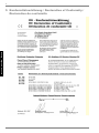
This heat pump conforms to all relevant DIN/VDE regulations
and EU directives. Refer to the EC Declaration of Conformity in
the appendix for details.
The heat pump must be connected to the power supply in compliance with all relevant VDE, EN and IEC standards. Any further
connection requirements stipulated by local utility companies
must also be observed.
The heat pump is to be connected to the heat source system and
the heating system in accordance with all applicable regulations.
Persons, especially children, who are not capable of operating
the device safely due to their physical, sensory or mental abilities
or their inexperience or lack of knowledge, must not operate this
device without supervision or instruction by the person in charge.
Children must be supervised to ensure that they do not play with
the device.
E-2
2.1
Application
The water-to-water heat pump is designed for use in existing or
newly built heating systems. Water is used as the heat transfer
medium. It can be supplied by wells or other water systems.
In order to eliminate the risk of corrosion at the evaporator, the
well water must be evaluated regarding the corrosion behaviour
of metallic materials according to DIN 50930.
Details can be found in the project planning and installation manual for heat pumps for heating purposes.
ATTENTION!
The well water must comply with the required water quality standards.
2.2
Operating Principle
A well pump conveys the water to the evaporator of the heat
pump. There the heat is transferred to the refrigerant in the refrigerating circuit.
The refrigerant is drawn in by the electrically driven compressor,
compressed and “pumped” to a higher temperature level. The
electrical power needed to run the compressor is not lost in this
process. Most of it is absorbed by the refrigerant as well.
Subsequently, the refrigerant is passed through the condenser
where it transfers its heat energy to the heating water.
Depending on the set operating point (thermostat setting), the
heating water is thus heated up to a max. of 60 °C.
4
3
Basic Device
4
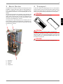
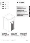
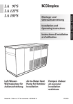
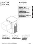
The basic device consists of a ready-to-use heat pump for indoor
installation, complete with casing, switch box and integrated controller. The refrigerating cycle contains the refrigerant R407C.
The refrigerant is CFC-free, non-ozone depleting and non-combustible.
All components required for the operation of the heat pump are
located in the switch box. An external wall temperature sensor including fixing accessories and a dirt trap are supplied with the
heat pump. The power feed for the load current and the control
current must be installed by the customer.
Transport
A lift truck is suited for transporting the unit on a level surface.
Carrying straps may be used if the heat pump needs to be transported on an uneven surface or carried up or down stairs. These
straps can be passed directly underneath the wooden pallet.
ATTENTION!
The heat pump is not secured to the wooden pallet.
English
The supply lead of the well pump (to be provided by the customer) must be connected to the switch box. It is important to ensure that the integrated motor protection is sufficient for the pump
provided by the customer.
ATTENTION!
The heat pump must not be tilted more than 45° (in any direction).
Use the holes provided in the sides of the frame to lift the unit
without the pallet. The side panel assemblies must be removed
for this purpose. Any commercially available length of pipe can
be used as a carrying aid.
ATTENTION!
Do not use the holes in the panel assemblies for lifting the device!
1)
Evaporator
2)
Switch box
3)
Liquifier
4)
Compressor
www.dimplex.de
E-3
5
5
5.1
Set-up
General Information
The unit may only be installed indoors in rooms with low humidity
on a level, smooth and horizontal surface. The entire base of the
frame should lie directly on the floor to ensure a good soundproof
seal. If this is not the case, additional sound insulation measures
may be necessary.
English
The heat pump must be installed so that maintenance work can
be carried out without being hindered. This can be ensured by
maintaining a clearance of approx. 1 m in front of and on each
side of the heat pump.
6
Installation
6.1
General Information
The following connections need to be established on the heat
pump:
Flow and return flow of the well system
Flow and return flow of the heating system
Power supply
6.2
Heating System Connection
ATTENTION!
Flush the heating system prior to connecting the heat pump.
Before connecting the heating water system to the heat pump,
the heating system must be flushed to remove any impurities,
residue from sealants, etc. Any accumulation of deposits in the
liquifier could cause the heat pump to completely break down.
Once the heating system has been installed, it must be filled, deaerated and pressure-tested.
Minimum heating water flow rate
The minimum heating water flow rate through the heat pump
must be assured in all operating states of the heating system.
This can be accomplished, for example, by installing either a
manifold without differential pressure or an overflow valve. The
procedure for adjusting an overflow valve is described in the
Chapter Start-up.
5.2
Sound Emissions
The heat pump operates silently due to efficient sound insulation.
To prevent noise transmission to the foundation, a suitable,
sound dampening rubber mat should be placed underneath the
base frame of the heat pump.
To prevent any sound from being transmitted to the heating system, we recommend connecting the heat pump to the heating
system by means of hose sections.
Antifreeze protection for installation locations
prone to frost
The antifreeze function of the heat pump controller is active
whenever the controller and the heat circulating pumps are ready
for operation. If the heat pump is taken out of service or in the
event of a power failure, the system has to be drained. The heating circuit should be operated with a suitable antifreeze if heat
pump systems are implemented in buildings where a power failure can not be detected (holiday home).
6.3
Heat Source Connection
The following procedure must be observed when connecting the
heat source:
Connect the well pipes to the heat pump flow and return flow.
ATTENTION!
The well water must comply with the required water quality standards.
The hydraulic plumbing diagram must be adhered to.
E-4
7.3
Electrical Connection
The following electrical connections need to be established on
the heat pump.
Connection of the control line to the control panel of the heat
pump via terminal X1: L/N/PE.
Connection of the mains cable to the control panel of the
heat pump via terminal X5: L1/L2/L3/PE.
Connection of the mains cable of the well pump to the control panel of the heat pump via terminal X5: L11/L21/L31/PE.
Connection of the well pump (to be provided by the customer) to the control panel of the heat pump via terminal X1:
PE and pump contactor K5: 2/4/6.
Ensure that the supply voltage for these terminals cannot be
switched off by the tariff contactor when connecting the mains
cable of the well pump, in order to enable the turn-off delay of the
well pump.
All electrical components required for the operation of the heat
pump are located on the control panel.
For detailed instructions concerning the connection and functioning of the heat pump controller (e.g. external wall sensor included
in the scope of supply), refer to the operating manual supplied
with the controller.
An all-pole disconnecting device with a contact gap of at least
3 mm (e.g. utility blocking contactor or power contactor) as well
as a 3-pole circuit breaker with common tripping for all external
conductors have to be provided by the customer. The required
conductor cross-section is to be selected according to the power
consumption of the heat pump, the technical connection requirements of the respective utility company as well as all applicable
regulations. Details on the power consumption of the heat pump
are listed on both the product information sheet and the type
plate. The connection terminals are designed for a max. conductor cross section of 10 mm2.
ATTENTION!
Observe the clockwise rotating field when connecting the mains cable (if
rotating field is not clockwise, the heat pump will not work properly and
will be very noisy).
7
Commissioning
7.1
General Information
To ensure that start-up is performed correctly, it should only be
carried out by an after-sales service technician authorised by the
manufacturer. This may be a condition for extending the guarantee (see Warranty Service).
7.2
Preparation
The following items need to be checked prior to start-up:
The heat pump must be fully connected, as described in
Chapter 6.
The heat source system and the heating circuit must have
been filled and checked.
All valves that could impair proper flow in the well and heating circuits must be open.
The heat pump controller must be adapted to the heating
system in accordance with the controller’s operating instructions.
7.3
Start-up Procedure
The heat pump is started up via the heat pump controller.
ATTENTION!
The heat pump must be started up in accordance with the installation and
operating instructions of the heat pump controller.
If an overflow valve is fitted to assure the minimum heating water
flow rate, the valve must be set in accordance with the requirements of the respective heating system. Incorrect adjustment
can lead to faulty operation and increased energy consumption.
We recommend carrying out the following procedure to correctly
adjust the overflow valve:
Close all of the heating circuits that may also be closed during
operation (depending on the type of heat pump usage) so that
the most unfavourable operating state - with respect to the water
flow rate - is achieved. This normally means the heating circuits
of the rooms on the south and west sides of the building. At least
one heating circuit must remain open (e.g. bathroom).
The overflow valve should be opened far enough to produce the
maximum temperature spread between the heating flow and return flow listed in the table below for the current heat source temperature. The temperature spread should be measured as close
as possible to the heat pump. The heating element of mono energy systems should be disconnected.
Heat source
temperature
From
To
Max. temperature spread
between heating flow and return
flow
7° C
12° C
10 K
13° C
18° C
11 K
19° C
25° C
12 K
Any faults occurring during operation are displayed on the heat
pump controller and can be corrected as described in the operating manual of the heat pump controller.
www.dimplex.de
E-5
English
6.4
8
8
Maintenance and
Cleaning
8.1
Maintenance
The heat pump is maintenance-free. To prevent faults due to
sediment in the heat exchangers, care must be taken to ensure
that no impurities can enter either the heat source system or the
heating system. In the event that operating malfunctions due to
contamination occur nevertheless, the system should be cleaned
as described below.
English
8.2
Cleaning the Heating System
The ingress of oxygen into the heating water circuit may result in
the formation of oxidation products (rust), particularly if steel
components are used. This oxygen enters the heating system via
the valves, the circulating pumps and/or plastic pipes. It is therefore essential - in particular with respect to the piping of underfloor heating systems - that only diffusion-proof materials are
used.
ATTENTION!
We recommend the installation of a suitable corrosion protection system
to prevent the formation of deposits (e.g. rust) in the condenser of the
heat pump.
Residue from lubricants and sealants may also contaminate the
heating water.
8.4
Water Quality Requirements
The ground water should not contain any substances that could
form deposits. The limit values for iron (< 0.2 mg/l) and manganese (< 0.1 mg/l) must be adhered to prevent iron ochre sedimentation in the heat pump system.
The use of surface water or water containing salt is not permissible. Your local water utility can provide you with general information regarding the possible use of ground water. Water analyses
are carried out by specially-equipped laboratories.
It is not necessary to carry out a water analysis with regard to
evaporator corrosion if the annual mean temperature of the
ground water does not exceed
13 °C). In this case, the limit values for iron and manganese must
be adhered to (iron ochre sedimentation).
9
Faults / TroubleShooting
This heat pump is a quality product and is designed for troublefree operation. In the event that a fault should occur, it will be
shown on the heat pump manager display. Simply consult the
Faults and Trouble-Shooting page in the operating instructions of
the heat pump controller.
If you cannot correct the fault yourself, please contact your aftersales service technician.
ATTENTION!
In the case of severe contamination leading to a reduction in the
performance of the liquifier in the heat pump, the system must be
cleaned by a heating technician.
Any work on the heat pump may only be performed by authorised and
qualified after-sales service technicians.
According to today’s state of knowledge, we recommend using a
5 % phosphoric acid solution for cleaning purposes. However, if
cleaning needs to be performed more frequently, a 5 % formic
acid solution should be used.
Disconnect all electrical circuits from the power source prior to opening
the device.
In either case, the cleaning fluid should be at room temperature.
We recommend flushing the heat exchanger in the direction opposite to the normal flow direction.
To prevent acidic cleaning agents from entering the heating system circuit, we recommend connecting the flushing device directly to the flow and return flow of the liquifier. It is important that
the system be thoroughly flushed using appropriate neutralising
agents to prevent any damage from being caused by cleaning
agent residue remaining in the system.
Acids must be used with great care and all relevant regulations of
the employers’ liability insurance associations must be adhered
to.
If in doubt, contact the manufacturer of the chemicals!
8.3
Cleaning the Heat Source
System
A dirt trap is inserted in the heat source inlet of the heat pump to
protect the evaporator against the ingress of impurities. When
the system is first put into operation, the filter screen of the dirt
trap should be cleaned in relatively short intervals. These intervals can be prolonged once the amount of impurities decreases.
E-6
ATTENTION!
10 Decommissioning /
Disposal
Before removing the heat pump, disconnect it from the power
source and close all valves. Observe all environmentally-relevant
requirements regarding the recovery, recycling and disposal of
materials and components in accordance with all applicable
standards. Particular attention should be paid to the proper disposal of refrigerants and refrigeration oils.
11
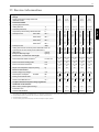
11 Device Information
Type and order code
WI 9TE
2
Design
2.1
Degree of protection according to EN 60 529
2.2
Installation Location
3
Performance data
3.1
Operating temperature limits:
WI 18TE
WI 22TE
WI 27TE
IP 20
IP 20
IP 20
IP 20
IP20
Indoors
Indoors
Indoors
Indoors
Indoors
Heating water flow
°C
Up to 58
Up to 58
Up to 58
Up to 58
Up to 58
Cold water (heat source)
°C
+7 to +25
+7 to +25
+7 to +25
+7 to +25
+7 to +25
3.2
Temperature spread of heating waterat W10 / W35
3.3
1
3.4
WI 14TE
Heat output / COP
K
9.5
kW / ---
6.9 /
2.5
12.2 /
2.5
14.9 /
3.0
19.0 /
3.2
24.6 /
3.2
at W10 / W50 1
kW / ---
7.7 /
3.2
13.4 /
3.6
16.3 /
3.7
20.8 /
3.8
26.4 /
3.8
at W10 / W45 1
kW / ---
at W10 / W35 1
kW / ---
at W7 / W55
Sound power level
5.0
8.8
5.0
7.6 /
3.5
8.3 /
5.1
dB(A)
8.2 /
4.9
9.2
5.0
13.2 /
3.8
9.6
5.0
16.1 /
4.0
9.4
5.0
20.5 /
4.0
26.0 /
4.1
13.6 / 13.5 / 17.1 / 16.9 / 21.5 / 21.3 / 26.4 / 26.1 /
5.2
5.0
5.3
5.2
5.5
5.3
5.1
4.9
53
55
55
3.5
Heating water flow with an internal pressure differential of m³/h / Pa
0.75 / 1.4 / 1.3 / 2.3 / 1.6 /
7000 24000 7000 22000 2600
3.6
Cold water flow rate at an internal pressure differential of
(heat source)
m³/h / Pa
2.0 /
6200
type / kg
R407C / 1.7
58
2.8 /
7600
59
2.0 / 3.7 / 2.4 / 4.5 /
8000 24300 12500 36000
1.9 / 3.3 / 3.2 / 4.0 / 3.6 / 5.0 / 4.8 / 7.0 / 6.7 /
5600 19000 13000 12000 9500 20000 17900 16000 14900
3.7
Refrigerant; total filling weight
4
Dimensions, connections and weight
4.1
Device dimensions without connections 2
H x W x L mm
1445 x 650 x 1445 x 650 x 1445 x 650 x 1445 x 650 x 1445 x 650 x
575
575
575
575
575
4.2
Device connections to heating system
Inch
G 1¼" exter- G 1¼" exter- G 1¼" exter- G 1¼" exter- G 1¼" external
nal
nal
nal
nal
4.3
Device connections to heat source
Inch
G 1¼" exter- G 1¼" exter- G 1½" exter- G 1½" exter- G 1½" external
nal
nal
nal
nal
4.4
Weight of the transportable unit(s) incl. packing
kg
5
Electrical Connection
5.1
Nominal voltage; fuse protection
5.2
Nominal power consumption
1
V/A
W10 W35
189
259
400 / 16
400 / 16
400 / 16
400 / 20
400 / 20
kW
1.62
1.68
A
5.4
Nominal current W10 W35 / cos ϕ
A / ---
2.9 /
0.8
6
Complies with the European safety regulations
Additional model features
7.2
Performance levels
7.3
Controller internal/external
R407C / 4.5
187
Starting current with soft starter
Water in device protected against freezing 4
R407C / 3.2
168
5.3
7.1
R407C / 3.5
156
30 (without
SS)
7
R407C / 1.6
3.03 /
0.8
2.64
2.72
3.21
26
4.8 /
0.8
4.91 /
0.8
3.27
28
5.8 /
0.8
5.90 /
0.8
3.93
4.02
5.15
27
7.0 / 7.25 /
0.8
0.8
5.29
29
9.4 /
0.8
9.54 /
0.8
3
3
3
3
3
Yes
Yes
Yes
Yes
Yes
1
1
1
1
1
Internal
Internal
Internal
Internal
Internal
1. This data indicates the size and capacity of the system. For an analysis of the economic and energy efficiency of the system, both the bivalence point and the regulation should
also be taken into consideration. The specified values, e.g. W10 / W55, have the following meaning: Heat source temperature 10 °C and heating water flow temperature 55 °C.
2. Note that additional space is required for pipe connections, operation and maintenance.
3. See CE declaration of conformity
4. The heat circulating pump and the heat pump controller must always be ready for operation.
www.dimplex.de
E-7
English
1
Anhang / Appendix / Annexes
1
Maßbild / Dimension Drawing / Schéma coté ............................................................................ A-II
2
Diagramme / Diagrams / Diagrammes ....................................................................................... A-III
2.1
2.2
2.3
2.4
2.5
Stromlaufpläne / Circuit Diagrams / Schémas électriques.................................................... A-VIII
3.1 Steuerung / Control / Commande WI 9TE - WI 22TE..........................................................................A-VIII
3.2 Last / Load / Charge WI 9TE - WI 22TE ................................................................................................A-IX
3.3 Klemmenanschlussplan / Terminal Connection Plan / Schéma de connexion des bornes WI 9TE WI 22TE..................................................................................................................................................A-X
3.4 Legende / Legend / Légende WI 9TE - WI 22TE...................................................................................A-XI
3.5 Steuerung / Control / Commande WI 27TE ..........................................................................................A-XII
3.6 Last / Load / Charge WI 27TE .............................................................................................................A-XIII
3.7 Klemmenanschlussplan / Terminal Connection Plan / Schéma de connexion des bornes WI 27TE . A-XIV
3.8 Legende / Legend / Légende WI 27TE................................................................................................ A-XV
4
Hydraulisches Prinzipschema / Hydraulic Plumbing Diagram / Schéma hydraulique .......A-XVI
4.1 Darstellung / Schematic View / Représentation.................................................................................. A-XVI
4.2 Legende / Legend / Légende............................................................................................................. A-XVII
5
Konformitätserklärung / Declaration of Conformity / Déclaration de conformité .............A-XVIII
www.dimplex.de
A-I
Anhang · Appendix · Annexes
3
Kennlinien / Characteristic Curves / Courbes caractéristiques WI 9TE................................................. A-III
Kennlinien / Characteristic Curves / Courbes caractéristiques WI 14TE...............................................A-IV
Kennlinien / Characteristic Curves / Courbes caractéristiques WI 18TE................................................A-V
Kennlinien / Characteristic Curves / Courbes caractéristiques WI 22TE...............................................A-VI
Kennlinien / Characteristic Curves / Courbes caractéristiques WI 27TE..............................................A-VII
A-II
FD$SSUR[HQY FD$SSUR[HQY 5DFFRUGVF{WpVRXUFHGHFKDOHXU
:,7(
)LOHWDJHH[WpULHXU³)LOWUHjHDXDYHFILOHWDJHH[W´
:,7(
)LOHWDJHH[WpULHXU³)LOWUHjHDXDYHFILOHWDJHH[W´
5DFFRUGVF{WpFKDXIIDJH
:,7(
)LOHWDJHH[WpULHXU³
&RQQHFWLRQVRQWKHKHDWVRXUFHVLGH
:,7(
³H[WHUQDOWKUHDG:DWHUILOWHUZLWK³H[WHUQDOWKUHDG
:,7(
³H[WHUQDOWKUHDG:DWHUILOWHUZLWK³H[WHUQDOWKUHDG
&RQQHFWLRQVRQWKHKHDWLQJVLGH
:,7(
³H[WHUQDOWKUHDG
:lUPHTXHOOHQVHLWLJH$QVFKOVVH
:,7(
³$XHQJHZLQGH :DVVHUILOWHUPLW
$XHQJHZLQGH
:,&6
³$XHQJHZLQGH :DVVHUILOWHUPLW
$XHQJHZLQGH
+HL]XQJVVHLWLJH$QVFKOVVH
:,7(
³$XHQJHZLQGH
IU:,7(
)RU:,7(
SRXU:,7(
Anhang · Appendix · Annexes
PLWPRQWLHUWHP:DVVHUILOWHU
:LWKPRXQWHGZDWHUILOWHU
DYHFILOWUHjHDXSUpPRQWp
5HWRXUHDXGHFKDXIIDJH
HQWUpHGDQVOD3$&
+HDWLQJZDWHUUHWXUQIORZ
+HDWSXPSLQOHW
+HL]XQJ5FNODXI
(LQJDQJLQ:lUPHSXPSH
6RUWLHVRXUFHGHFKDOHXU
+HDWVRXUFHIORZ
+HDWSXPSRXWOHW
:lUPHTXHOOH9RUODXI
$XVJDQJDXV:lUPHSXPSH
(QWUpHVRXUFHGHFKDOHXU
+HDWVRXUFHUHWXUQIORZ
+HDWSXPSLQOHW
:lUPHTXHOOH5FNODXI
(LQJDQJLQ:lUPHSXPSH
$OOHUHDXGHFKDXIIDJH
VRUWLHGHOD3$&
+HDWLQJZDWHUIORZ
+HDWSXPSRXWOHW
+HL]XQJ9RUODXI
$XVJDQJDXV:lUPHSXPSH
1
1 Maßbild / Dimension Drawing / Schéma coté
2.1
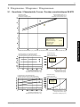
2 Diagramme / Diagrams / Diagrammes
2.1
Kennlinien / Characteristic Curves / Courbes caractéristiques WI 9TE
+HL]OHLVWXQJLQ>N:@
+HDWLQJFDSDFLW\LQ>N:@
3XLVVDQFHGHFKDXIIDJHHQ>N:@
:DVVHUDXVWULWWVWHPSHUDWXULQ>&@
:DWHURXWOHWWHPSHUDWXUHLQ>&@
7HPSpUDWXUHGHVRUWLHGHO
HDXHQ>&@
%HGLQJXQJHQÂ&RQGLWLRQVÂ&RQGLWLRQV
.DOWZDVVHUGXUFKVDW]
&ROGZDWHUIORZUDWH
'pELWG
HDXIURLGH
PK
Anhang · Appendix · Annexes
+HL]ZDVVHUGXUFKVDW]
+HDWLQJZDWHUIORZUDWH
'pELWG
HDXGHFKDXIIDJH
PK
.DOWZDVVHUHLQWULWWVWHPSHUDWXULQ>&@Â&ROGZDWHULQOHWWHPSHUDWXUHLQ>&@Â7HPSpUDWXUHG
HQWUpHG
HDXIURLGHHQ>&@
/HLVWXQJVDXIQDKPHLQFO3XPSHQOHLVWXQJVDQWHLO
3RZHUFRQVXPSWLRQLQFOSRZHULQSXWWRSXPS
&RQVRPPDWLRQGHSXLVVDQFH\FRPSULVSDUWGHFRQVRPPDWLRQGHODSRPSH
'UXFNYHUOXVWLQ>3D@
3UHVVXUHORVVLQ>3D@
3HUWHGHSUHVVLRQHQ>3D@
9HUGDPSIHU
(YDSRUDWRU
(YDSRUDWHXU
.DOWZDVVHUHLQWULWWVWHPSHUDWXULQ>&@
&ROGZDWHULQOHWWHPSHUDWXUHLQ>&@
7HPSpUDWXUHG
HQWUpHG
HDXIURLGHHQ>&@
/HLVWXQJV]DKOLQFO3XPSHQOHLVWXQJVDQWHLO
&RHIILFLHQWRISHUIRUPDQFHLQFOSRZHULQSXWWRSXPS
&RHIILFLHQWGHSHUIRUPDQFH\FRPSULVSDUWGHFRQVRPPDWLRQGHODSRPSH
.DOWZDVVHUGXUFKIOXVVLQ>PK@
&ROGZDWHUIORZUDWHLQ>PK@
'pELWG
HDXIURLGHHQ>PK@
'UXFNYHUOXVWLQ>3D@
3UHVVXUHORVVLQ>3D@
3HUWHGHSUHVVLRQHQ>3D@
9HUIOVVLJHU
&RQGHQVHU
&RQGHQVHXU
.DOWZDVVHUHLQWULWWVWHPSHUDWXULQ>&@
&ROGZDWHULQOHWWHPSHUDWXUHLQ>&@
7HPSpUDWXUHG
HQWUpHG
HDXIURLGHHQ>&@
www.dimplex.de
+HL]ZDVVHUGXUFKIOXVVLQ>PK@
+HDWLQJZDWHUIORZUDWHLQ>PK@
'pELWG
HDXGHFKDXIIDJHHQ>PK@
A-III
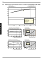
2.2
2.2
Kennlinien / Characteristic Curves / Courbes caractéristiques WI 14TE
+HL]OHLVWXQJLQ>N:@
+HDWLQJFDSDFLW\LQ>N:@
3XLVVDQFHGHFKDXIIDJHHQ>N:@
:DVVHUDXVWULWWVWHPSHUDWXULQ>&@
:DWHURXWOHWWHPSHUDWXUHLQ>&@
7HPSpUDWXUHGHVRUWLHGHO
HDXHQ>&@
%HGLQJXQJHQÂ&RQGLWLRQVÂ&RQGLWLRQV
+HL]ZDVVHUGXUFKVDW]
+HDWLQJZDWHUIORZUDWH
'pELWG
HDXGHFKDXIIDJH
PK
.DOWZDVVHUGXUFKVDW]
&ROGZDWHUIORZUDWH
'pELWG
HDXIURLGH
PK
Anhang · Appendix · Annexes
.DOWZDVVHUHLQWULWWVWHPSHUDWXULQ>&@Â&ROGZDWHULQOHWWHPSHUDWXUHLQ>&@Â7HPSpUDWXUHG
HQWUpHG
HDXIURLGHHQ>&@
/HLVWXQJVDXIQDKPHLQFO3XPSHQOHLVWXQJVDQWHLO
3RZHUFRQVXPSWLRQLQFOSRZHULQSXWWRSXPS
&RQVRPPDWLRQGHSXLVVDQFH\FRPSULVSDUWGHFRQVRPPDWLRQGHODSRPSH
'UXFNYHUOXVWLQ>3D@
3UHVVXUHORVVLQ>3D@
3HUWHGHSUHVVLRQHQ>3D@
9HUGDPSIHU
(YDSRUDWRU
(YDSRUDWHXU
.DOWZDVVHUHLQWULWWVWHPSHUDWXULQ>&@
&ROGZDWHULQOHWWHPSHUDWXUHLQ>&@
7HPSpUDWXUHG
HQWUpHG
HDXIURLGHHQ>&@
/HLVWXQJV]DKOLQFO3XPSHQOHLVWXQJVDQWHLO
&RHIILFLHQWRISHUIRUPDQFHLQFOSRZHULQSXWWRSXPS
&RHIILFLHQWGHSHUIRUPDQFH\FRPSULVSDUWGHFRQVRPPDWLRQGHODSRPSH
.DOWZDVVHUGXUFKIOXVVLQ>PK@
&ROGZDWHUIORZUDWHLQ>PK@
'pELWG
HDXIURLGHHQ>PK@
'UXFNYHUOXVWLQ>3D@
3UHVVXUHORVVLQ>3D@
3HUWHGHSUHVVLRQHQ>3D@
9HUIOVVLJHU
&RQGHQVHU
&RQGHQVHXU
.DOWZDVVHUHLQWULWWVWHPSHUDWXULQ>&@
&ROGZDWHULQOHWWHPSHUDWXUHLQ>&@
7HPSpUDWXUHG
HQWUpHG
HDXIURLGHHQ>&@
A-IV
+HL]ZDVVHUGXUFKIOXVVLQ>PK@
+HDWLQJZDWHUIORZUDWHLQ>PK@
'pELWG
HDXGHFKDXIIDJHHQ>PK@
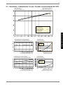
2.3
2.3
Kennlinien / Characteristic Curves / Courbes caractéristiques WI 18TE
+HL]OHLVWXQJLQ>N:@
+HDWLQJFDSDFLW\LQ>N:@
3XLVVDQFHGHFKDXIIDJHHQ>N:@
:DVVHUDXVWULWWVWHPSHUDWXULQ>&@
:DWHURXWOHWWHPSHUDWXUHLQ>&@
7HPSpUDWXUHGHVRUWLHGHO
HDXHQ>&@
+HL]ZDVVHUGXUFKVDW]
+HDWLQJZDWHUIORZUDWH
'pELWG
HDXGHFKDXIIDJH
PK
.DOWZDVVHUGXUFKVDW]
&ROGZDWHUIORZUDWH
'pELWG
HDXIURLGH
PK
Anhang · Appendix · Annexes
%HGLQJXQJHQÂ&RQGLWLRQVÂ&RQGLWLRQV
.DOWZDVVHUHLQWULWWVWHPSHUDWXULQ>&@Â&ROGZDWHULQOHWWHPSHUDWXUHLQ>&@Â7HPSpUDWXUHG
HQWUpHG
HDXIURLGHHQ>&@
/HLVWXQJVDXIQDKPHLQFO3XPSHQOHLVWXQJVDQWHLO
3RZHUFRQVXPSWLRQLQFOSRZHULQSXWWRSXPS
&RQVRPPDWLRQGHSXLVVDQFH\FRPSULVSDUWGHFRQVRPPDWLRQGHODSRPSH
'UXFNYHUOXVWLQ>3D@
3UHVVXUHORVVLQ>3D@
3HUWHGHSUHVVLRQHQ>3D@
9HUGDPSIHU
(YDSRUDWRU
(YDSRUDWHXU
.DOWZDVVHUHLQWULWWVWHPSHUDWXULQ>&@
&ROGZDWHULQOHWWHPSHUDWXUHLQ>&@
7HPSpUDWXUHG
HQWUpHG
HDXIURLGHHQ>&@
/HLVWXQJV]DKOLQFO3XPSHQOHLVWXQJVDQWHLO
&RHIILFLHQWRISHUIRUPDQFHLQFOSRZHULQSXWWRSXPS
&RHIILFLHQWGHSHUIRUPDQFH\FRPSULVSDUWGHFRQVRPPDWLRQGHODSRPSH
.DOWZDVVHUGXUFKIOXVVLQ>PK@
&ROGZDWHUIORZUDWHLQ>PK@
'pELWG
HDXIURLGHHQ>PK@
'UXFNYHUOXVWLQ>3D@
3UHVVXUHORVVLQ>3D@
3HUWHGHSUHVVLRQHQ>3D@
9HUIOVVLJHU
&RQGHQVHU
&RQGHQVHXU
.DOWZDVVHUHLQWULWWVWHPSHUDWXULQ>&@
&ROGZDWHULQOHWWHPSHUDWXUHLQ>&@
7HPSpUDWXUHG
HQWUpHG
HDXIURLGHHQ>&@
www.dimplex.de
+HL]ZDVVHUGXUFKIOXVVLQ>PK@
+HDWLQJZDWHUIORZUDWHLQ>PK@
'pELWG
HDXGHFKDXIIDJHHQ>PK@
A-V
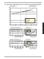
2.4
2.4
Kennlinien / Characteristic Curves / Courbes caractéristiques WI 22TE
+HL]OHLVWXQJLQ>N:@
+HDWLQJFDSDFLW\LQ>N:@
3XLVVDQFHGHFKDXIIDJHHQ>N:@
:DVVHUDXVWULWWVWHPSHUDWXULQ>&@
:DWHURXWOHWWHPSHUDWXUHLQ>&@
7HPSpUDWXUHGHVRUWLHGHO
HDXHQ>&@
%HGLQJXQJHQÂ&RQGLWLRQVÂ&RQGLWLRQV
+HL]ZDVVHUGXUFKVDW]
+HDWLQJZDWHUIORZUDWH
'pELWG
HDXGHFKDXIIDJH
PK
.DOWZDVVHUGXUFKVDW]
&ROGZDWHUIORZUDWH
'pELWG
HDXIURLGH
PK
Anhang · Appendix · Annexes
.DOWZDVVHUHLQWULWWVWHPSHUDWXULQ>&@Â&ROGZDWHULQOHWWHPSHUDWXUHLQ>&@Â7HPSpUDWXUHG
HQWUpHG
HDXIURLGHHQ>&@
/HLVWXQJVDXIQDKPHLQFO3XPSHQOHLVWXQJVDQWHLO
3RZHUFRQVXPSWLRQLQFOSRZHULQSXWWRSXPS
&RQVRPPDWLRQGHSXLVVDQFH\FRPSULVSDUWGHFRQVRPPDWLRQGHODSRPSH
'UXFNYHUOXVWLQ>3D@
3UHVVXUHORVVLQ>3D@
3HUWHGHSUHVVLRQHQ>3D@
9HUGDPSIHU
(YDSRUDWRU
(YDSRUDWHXU
.DOWZDVVHUHLQWULWWVWHPSHUDWXULQ>&@
&ROGZDWHULQOHWWHPSHUDWXUHLQ>&@
7HPSpUDWXUHG
HQWUpHG
HDXIURLGHHQ>&@
/HLVWXQJV]DKOLQFO3XPSHQOHLVWXQJVDQWHLO
&RHIILFLHQWRISHUIRUPDQFHLQFOSRZHULQSXWWRSXPS
&RHIILFLHQWGHSHUIRUPDQFH\FRPSULVSDUWGHFRQVRPPDWLRQGHODSRPSH
.DOWZDVVHUGXUFKIOXVVLQ>PK@
&ROGZDWHUIORZUDWHLQ>PK@
'pELWG
HDXIURLGHHQ>PK@
'UXFNYHUOXVWLQ>3D@
3UHVVXUHORVVLQ>3D@
3HUWHGHSUHVVLRQHQ>3D@
9HUIOVVLJHU
&RQGHQVHU
&RQGHQVHXU
.DOWZDVVHUHLQWULWWVWHPSHUDWXULQ>&@
&ROGZDWHULQOHWWHPSHUDWXUHLQ>&@
7HPSpUDWXUHG
HQWUpHG
HDXIURLGHHQ>&@
A-VI
+HL]ZDVVHUGXUFKIOXVVLQ>PK@
+HDWLQJZDWHUIORZUDWHLQ>PK@
'pELWG
HDXGHFKDXIIDJHHQ>PK@
2.5
2.5
Kennlinien / Characteristic Curves / Courbes caractéristiques WI 27TE
+HL]OHLVWXQJLQ>N:@
+HDWLQJFDSDFLW\LQ>N:@
3XLVVDQFHGHFKDXIIDJHHQ>N:@
:DVVHUDXVWULWWVWHPSHUDWXULQ>&@
:DWHURXWOHWWHPSHUDWXUHLQ>&@
7HPSpUDWXUHGHVRUWLHGHO
HDXHQ>&@
+HL]ZDVVHUGXUFKVDW]
+HDWLQJZDWHUIORZUDWH
'pELWG
HDXGHFKDXIIDJH
PK
.DOWZDVVHUGXUFKVDW]
&ROGZDWHUIORZUDWH
'pELWG
HDXIURLGH
PK
Anhang · Appendix · Annexes
%HGLQJXQJHQÂ&RQGLWLRQVÂ&RQGLWLRQV
.DOWZDVVHUHLQWULWWVWHPSHUDWXULQ>&@Â&ROGZDWHULQOHWWHPSHUDWXUHLQ>&@Â7HPSpUDWXUHG
HQWUpHG
HDXIURLGHHQ>&@
/HLVWXQJVDXIQDKPHLQFO3XPSHQOHLVWXQJVDQWHLO
3RZHUFRQVXPSWLRQLQFOSRZHULQSXWWRSXPS
&RQVRPPDWLRQGHSXLVVDQFH\FRPSULVSDUWGHFRQVRPPDWLRQGHODSRPSH
'UXFNYHUOXVWLQ>3D@
3UHVVXUHORVVLQ>3D@
3HUWHGHSUHVVLRQHQ>3D@
9HUGDPSIHU
(YDSRUDWRU
(YDSRUDWHXU
.DOWZDVVHUHLQWULWWVWHPSHUDWXULQ>&@
&ROGZDWHULQOHWWHPSHUDWXUHLQ>&@
7HPSpUDWXUHG
HQWUpHG
HDXIURLGHHQ>&@
/HLVWXQJV]DKOLQFO3XPSHQOHLVWXQJVDQWHLO
&RHIILFLHQWRISHUIRUPDQFHLQFOSRZHULQSXWWRSXPS
&RHIILFLHQWGHSHUIRUPDQFH\FRPSULVSDUWGHFRQVRPPDWLRQGHODSRPSH
.DOWZDVVHUGXUFKIOXVVLQ>PK@
&ROGZDWHUIORZUDWHLQ>PK@
'pELWG
HDXIURLGHHQ>PK@
'UXFNYHUOXVWLQ>3D@
3UHVVXUHORVVLQ>3D@
3HUWHGHSUHVVLRQHQ>3D@
9HUIOVVLJHU
&RQGHQVHU
&RQGHQVHXU
.DOWZDVVHUHLQWULWWVWHPSHUDWXULQ>&@
&ROGZDWHULQOHWWHPSHUDWXUHLQ>&@
7HPSpUDWXUHG
HQWUpHG
HDXIURLGHHQ>&@
www.dimplex.de
+HL]ZDVVHUGXUFKIOXVVLQ>PK@
+HDWLQJZDWHUIORZUDWHLQ>PK@
'pELWG
HDXGHFKDXIIDJHHQ>PK@
A-VII
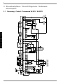
3
3 Stromlaufpläne / Circuit Diagrams / Schémas
électriques
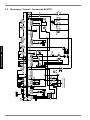
3.1
Steuerung / Control / Commande WI 9TE - WI 22TE
1HW]Â0DLQVÂ5pVHDX
Anhang · Appendix · Annexes
A-VIII
www.dimplex.de
(LQVSHLVXQJ9HUGLFKWHUEHU(986SHUUVFKW]
&RPSUHVVRULQIHHGYLDXWLOLW\EORFNLQJFRQWDFWRU
DOLPHQWDWLRQFRPSUHVVHXUYLDOHFRQWDFWHXUGH
EORFDJHVRFLpWpGLVWULEXWULFHG
pOHFWULFLWp
1HW]Â0DLQVÂ5pVHDX
Anhang · Appendix · Annexes
QLFKWLQ:,7(
QRWLQ:,7(
QHFRQFHUQHSDV:,7(
0RGLILHUOHFkEODJH
O¶DOLPHQWDWLRQGLUHFWHGHODSRPSH
GHSXLWVQ¶HVWSDVREOLJDWRLUHPHQW
QpFHVVDLUHSRXUOHVLQVWDOODWLRQV
VDQVFRQWDFWHXUGHEORFDJHGHOD
VRFLpWpGLVWULEXWULFHG
pOHFWULFLWp
&KDQJHZLULQJ
6\VWHPVZLWKRXWXWLOLW\EORFN
GRQRWUHTXLUHDGLUHFWLQIHHG
IRUWKHZHOOSXPS
9HUGUDKWXQJlQGHUQ
,Q$QODJHQRKQH(986SHUUH
NDQQGLHGLUHNWH(LQVSHLVXQJ
IUGLH%UXQQHQSXPSHHQWIDOOHQ
3XPSHQ7\S 1HQQVWURP
3XPSW\SH 1RPLQDOFXUUHQW
7\SHGHSRPSH &RXUDQWQRPLQDO
+HUVWHOOHUÂ0DQXIDFWXUHUÂ)DEULFDQW*UXQGIRV
$ :,7(±:,7(
$ :,7(
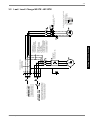
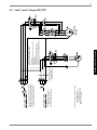
3.2
(LQVSHLVXQJ%UXQQHQSXPSHGLUHNW
'LUHFWZHOOSXPSLQIHHG
DOLPHQWDWLRQGLUHFWHSRPSHGHSXLWV
1HW]Â0DLQVÂ5pVHDX
9HUGUDKWXQJEHL$XVOLHIHUXQJ
:LULQJRQGHOLYHU\
&kEODJHjODOLYUDLVRQ
3.2
Last / Load / Charge WI 9TE - WI 22TE
A-IX
RGHUÂRUÂRX
A-X
3RVVLELOLWpGHVpOHFWLRQHHU
ODIRQFWLRQGH(
7KHIXQFWLRQRI(FDQ
EHVHOHFWHG
'LH)XQNWLRQYRQ(LVWZlKOEDU
.RQWDNWRIIHQ :3JHVSHUUW
&RQWDFWRSHQ +3GLVDEOHG
&RQWDFWRXYHUW 3$&EORTXpH
qPHHQWUpHHGHFRXSXUH
&RQWDFWRXYHUW 3$&EORTXpH
5HWLUHUOHSRQW$VLQpFHVVDLUH
QGGLVDEOHLQSXW
&RQWDFWRSHQ +3GLVDEOHG
%ULGJH$FDQEHUHPRYHGDFFRUGLQJWRQHHG
WHU6SHUUHLQJDQJ
.RQWDNWRIIHQ :3JHVSHUUW
%UFNH$EHL%HGDUIHQWIHUQHQ
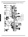
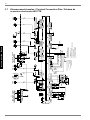
3.3
0LVFKHU+DXSWNUHLV
0L[HUIRUPDLQFLUFXLW
0pODQJHXUFLUFXLWSULQFLSDO
1HW]Â0DLQVÂ5pVHDX
Anhang · Appendix · Annexes
1HW]Â0DLQVÂ5pVHDX
3.3
Klemmenanschlussplan / Terminal Connection Plan / Schéma de
connexion des bornes WI 9TE - WI 22TE
+HL]VWDEÂ,PPHUVLRQKHDWHUÂ7KHUPRSORQJHXU
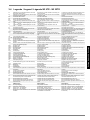
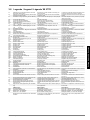
3.4
A1
Legende / Legend / Légende WI 9TE - WI 22TE
Drahtbrücke, muss eingelegt werden, wenn kein
Sperrschütz benötigt wird
Drahtbrücke, muss bei Verwendung des 2ten Sperreinganges entfernt werden
Thermostat Warmwasser
Thermostat Schwimmbadwasser
Elektr. Tauchheizkörper Warmwasser
2. Wärmeerzeuger (Heizkessel oder elekt. Heizstab)
Lastsicherung für N1-Relaisausgänge an J12 und
J13
4,0 ATr
Lastsicherung für N1-Relaisausgänge an J15 bis
J18
4,0 ATr
Pressostat Hochdruck
Pressostat Niederdruck (ab WI 22TE ist F5 ein
Begrenzer mit Handrückstellung)
Wire jumper, must be inserted if no blocking contactor is required
Wire jumper, must be removed if the 2nd disable
contactor is used
Hot water thermostat
Swimming pool water thermostat
Electric immersion heater hot water
2nd heat generator (boiler or electric heating element)
Load fuse for N1 relay outputs at J12 and J13
4.0 slow-acting
Load fuse for N1 relay outputs at J15 to J18
4.0 slow-acting
High-pressure switch
Low-pressure switch (F5 is a limiter with manual
reset as of the WI 22TE series)
F10
F15
Durchflussschalter
Überlastrelais für M11 / Das Überlastrelais ist für
die im Solepaket enthaltene Pumpe ausgelegt
H5*
J1...J18
K1
K5
K11*
Leuchte Störfernanzeige
Klemmensteckverbinder an N1
Schütz Verdichter
Schütz Primärpumpe
Elektron. Relais Störfernanzeige (auf Relaisbaugruppe)
Elektron. Relais für Schwimmbadwasserumwälzpumpe (auf Relaisbaugruppe)
Schütz für E10
Schütz für E9
EVU-Sperrschütz
SPR-Hilfsrelais
Verdichter
Primärpumpe
Heizungsumwälzpumpe
2. Heizkreisumwälzpumpe
Zusatzumwälzpumpe
Warmwasserumwälzpumpe
Schwimmbadwasserumwälzpumpe
Mischer Hauptkreis
Mischer 2. Heizkreis
Wärmepumpenregler
Sanftanlaufsteuerung (nicht in WI 9TE Geräten)
Flow rate switch
Overload relay for M11 / The overload relay is
designed for the pump contained in the brine package
Remote fault indicator lamp
Terminal connector at N1
Contactor for compressor
Contactor for primary pump
Electronic remote fault indicator relay (relay module)
Electronic relay for swimming pool water circulating
pump (on relay module)
Contactor for E10
Contactor for E9
Utility blocking contactor
SPR auxiliary relay
Compressor
Primary pump
Heat circulating pump
2. Heating circuit circulating pump
Auxiliary circulating pump
Hot water circulating pump
Swimming pool water circulating pump
Mixer for main circuit
Mixer for heating circuit 2
Heat pump controller
Soft start control (not in WI 9TE)
Relaisbaugruppe
Bedienteil
Außenfühler
Rücklauffühler
Warmwasserfühler (alternativ zum Warmwasserthermostat)
Fühler für 2ten Heizkreis
Eingefrierschutzfühler
Kodierwiderstand 49k9
Sicherheitstrenntransformator 230/24V AC-28VA
Relay module
Operating element
External sensor
Return flow sensor
Hot water sensor (as an alternative to the hot water
thermostat)
Sensor for heating circuit 2
Flow temperature limit sensor
Coding resistor 49k9
Safety isolating transformer 230/24 V AC-28 VA
Klemmenleiste Netz-Steuerung L/N/PE-230V AC50 Hz/Sicherungen/N- und PE-Verteiler
Klemmenleiste 24V AC-Verteiler
Klemmenleiste GND-Verteiler für Sensoren
Klemmenleiste Leistungseinspeisung 3L/PE400V AC-50 Hz
Terminal strip mains control L/N/PE-230V AC50 Hz/fuses/N and PE terminal blocks
Terminal strip 24V AC terminal block
Terminal strip for GND terminal block
Terminal strip for power supply 3L/PE-400V AC50 Hz
Le cavalier à fil doit être inséré en absence de disjoncteur de blocage du fournisseur d'énergie
Cavalier à fil à retirer si la 2e entrée de coupure est
utilisée
Thermostat eau chaude
Thermostat eau de piscine
Thermoplongeur élect. eau chaude
2e générateur de chaleur (chaudière ou cartouche
chauffante électr.)
Coupe-circuit de charge pour sorties de relais en
J12 et J13
4,0 ATr
Coupe-circuit de charge pour sorties de relais en
J15 jusqu’à J18
4,0 ATr
Pressostat haute pression
Pressostat basse pression (sur les appareils d'une
version ultérieure à WI 22TE, F5 est un limiteur
avec réinitialisation manuelle)
Commutateur de débit
Relais de surcharge pour M11 / le relais de surcharge est disponible dans le kit eau glycolée de la
pompe
Témoin de télédétection de pannes
Connecteur à bornes sur N1
Contacteur compresseur
Contacteur pompe primaire (PUP)
Relais électronique pour télédétection de pannes
(sur boîtier de relais)
Relais électronique pour circulateur eau de piscine
(sur module relais)
Contacteur pour E10
Contacteur pour E9
Contacteur de coupure du fournisseur d'énergie
Relais auxiliaire SPR
Compresseur
Pompe primaire
Circulateur de chauffage
2e circulateur circuit de chauffage
Circulateur supplémentaire
Circulateur d’eau chaude
Circulateur d’eau de piscine
Mélangeur circuit principal
Mélangeur 2e circuit de chauffage
Régulateur de pompe à chaleur
Commande de démarrage progressif (ne concerne
pas les appareils WI 9TE)
Module de relais
Commande
Sonde extérieure
Sonde de retour
Sonde d’eau chaude (alternative au thermostat eau
chaude)
Sonde pour 2e circuit de chauffage
Sonde antigel
Résistance de codage 49k9
Transformateur sectionneur de sécurité 230/24 V
AC-28 V A
Bornier commande réseau L/N/PE-230 V AC-50
Hz/fusibles/distributeur N et PE
Bornier distributeur pour 24 V AC
Bornier distributeur GND pour capteurs
Bornier alimentation puissance 3L/PE-400 V AC50 Hz
Abkürzungen:
EVU-Sperreingang
Zusätzlicher Sperreingang
Mischer AUF - 1ter Heizkreis
Mischer ZU - 1ter Heizkreis
Bauteile sind extern beizustellen, bzw. als Zubehör
erhältlich
Abbreviations:
Utility disable contactor
Supplementary disable contactor
Mixer OPEN - heating circuit 1
Mixer CLOSED - heating circuit 1
Components must be supplied by the customer or
are available as accessories
Abréviations :
Entrée de coupure fournisseur d'énergie
Entrée de « coupure courant » complémentaire
Mélangeur OUVERT - 1er circuit de chauffage
Mélangeur FERME - 1er circuit de chauffage
Pièces à fournir par le client (disponibles comme
accessoires)
A2
B3*
B4*
E9*
E10*
F2
F3
F4
F5
K12*
K20*
K21*
K22*
K23*
M1
M11*
M13*
M15*
M16*
M18*
M19*
M21*
M22*
N1
N7
N11*
N14
R1
R2
R3
R5
R6
R7
T1
X1
X2
X3
X5
EVS
SPR
MA*
MZ
*
www.dimplex.de
A-XI
Anhang · Appendix · Annexes
3.4
3.5
3.5
Steuerung / Control / Commande WI 27TE
1HW]Â0DLQVÂ5pVHDX
Anhang · Appendix · Annexes
A-XII
www.dimplex.de
3XPSHQ7\S 1HQQVWURP
3XPSW\SH 1RPLQDOFXUUHQW
7\SHGHSRPSH &RXUDQWQRPLQDO
+HUVWHOOHUÂ0DQXIDFWXUHUÂ)DEULFDQW*UXQGIRV
(LQVSHLVXQJ%UXQQHQSXPSHGLUHNW
'LUHFWZHOOSXPSLQIHHG
DOLPHQWDWLRQGLUHFWHSRPSHGHSXLWV
1HW]Â0DLQVÂ5pVHDX
Anhang · Appendix · Annexes
9HUGUDKWXQJEHL$XVOLHIHUXQJ
:LULQJRQGHOLYHU\
&kEODJHjODOLYUDLVRQ
9HUGUDKWXQJlQGHUQ
,Q$QODJHQRKQH(986SHUUHNDQQGLHGLUHNWH
(LQVSHLVXQJIUGLH%UXQQHQSXPSHHQWIDOOHQ
&KDQJHZLULQJ
6\VWHPVZLWKRXWXWLOLW\EORFNGRQRWUHTXLUHDGLUHFWLQIHHG
IRUWKHZHOOSXPS
0RGLILHUOHFkEODJH
O¶DOLPHQWDWLRQGLUHFWHGHODSRPSHGHSXLWVQ¶HVWSDV
REOLJDWRLUHPHQWQpFHVVDLUHSRXUOHVLQVWDOODWLRQVVDQV
FRQWDFWHXUGHEORFDJHGHODVRFLpWpGLVWULEXWULFHG
pOHFWULFLWp
3.6
(LQVSHLVXQJ9HUGLFKWHUEHU(986SHUUVFKW]
&RPSUHVVRULQIHHGYLDXWLOLW\EORFNLQJFRQWDFWRU
DOLPHQWDWLRQFRPSUHVVHXUYLDOHFRQWDFWHXUGH
EORFDJHVRFLpWpGLVWULEXWULFHG
pOHFWULFLWp
1HW]Â0DLQVÂ5pVHDX
3.6
Last / Load / Charge WI 27TE
A-XIII
RGHUÂRUÂRX
A-XIV
3RVVLELOLWpGHVpOHFWLRQHHU
ODIRQFWLRQGH(
7KHIXQFWLRQRI(FDQ
EHVHOHFWHG
qPHHQWUpHHGHFRXSXUH
&RQWDFWRXYHUW 3$&EORTXpH
5HWLUHUOHSRQW$VLQpFHVVDLUH
QGGLVDEOHLQSXW
&RQWDFWRSHQ +3GLVDEOHG
%ULGJH$FDQEHUHPRYHGDFFRUGLQJWRQHHG
WHU6SHUUHLQJDQJ
.RQWDNWRIIHQ :3JHVSHUUW
%UFNH$EHL%HGDUIHQWIHUQHQ
3.7
'LH)XQNWLRQYRQ(LVWZlKOEDU
1HW]Â0DLQVÂ5pVHDX
Anhang · Appendix · Annexes
[
1HW]Â0DLQVÂ5pVHDX
3.7
Klemmenanschlussplan / Terminal Connection Plan / Schéma de
connexion des bornes WI 27TE
+HL]VWDEÂ,PPHUVLRQKHDWHUÂ
7KHUPRSORQJHXU
3.8
A1
A2
B1
B3*
B4*
E9*
E10*
F2
F3
F4
F5
F10
F12
F14
H5*
J1...J18
K1
K1.1
K1.2
K5
K11*
K12*
K20*
K21*
K22*
K23*
M1
M11*
M13*
M15*
M16*
M18*
M19*
M21*
M22*
N1
N7
N11*
N14
Q1
Q2
R1
R2
R3*
R5
R6
R7
R9
T1
X1
X2
X3
X5
Y4
EVS
SPR
MA*
MZ
*
Legende / Legend / Légende WI 27TE
Drahtbrücke, muss eingelegt werden, wenn kein
Sperrschütz benötigt wird
Drahtbrücke, muss bei Verwendung des 2ten Sperreinganges entfernt werden
Pressostat Leistungsanpassung bei WW-Bereitung
Klemmenleiste Netz-Steuerung L/N/PE-230V AC50 Hz/Sicherungen/N- und PE-Verteiler
Klemmenleiste 24V AC-Verteiler
Klemmenleiste GND-Verteiler für Sensoren
Klemmenleiste Leistungseinspeisung 3L/PE400V AC-50 Hz
Magnetventil-Leistungsanpassung bei WW-Bereitung
Terminal strip mains control L/N/PE-230V AC50 Hz/fuses/N and PE terminal blocks
Terminal strip 24V AC terminal block
Terminal strip for GND terminal block for sensors
Terminal strip for power supply 3L/PE-400V AC50 Hz
Solenoid valve pressure switch, flexible capacity for
DHW preparation
Le cavalier à fil doit être inséré en absence de disjoncteur de blocage du fournisseur d'énergie
Cavalier à fil à retirer si la 2e entrée de coupure est
utilisée
Pressostat adaptation de la puissance pour préparation d’eau chaude
Thermostat eau chaude
Thermostat eau de piscine
Thermoplongeur élect. eau chaude
2e générateur de chaleur
Coupe-circuit de charge pour sorties de relais en
J12 et J13
4,0 ATr
Coupe-circuit de charge pour sorties de relais en
J15 jusqu’à J18
4,0 ATr
Pressostat haute pression
Pressostat basse pression - limiteur avec réinitialisation manuelle
Commutateur de débit
Contrôleur de température N7
Protection moteur électronique compresseur 1
Témoin de télédétection de pannes
Connecteur à bornes sur N1
Contacteur pour M1
Contacteur limitation du courant de démarrage M1
Relais temporisé retard K1
Contacteur pour M11
Relais électronique pour H5
Relais électronique pour M19
Contacteur pour E10
Contacteur pour E9
Contacteur de coupure du fournisseur d'énergie
Relais auxiliaire SPR
Compresseur
Pompe primaire
Circulateur de chauffage
2e circulateur circuit de chauffage
Circulateur supplémentaire
Circulateur d’eau chaude
Circulateur d’eau de piscine
Mélangeur circuit principal
Mélangeur 2e circuit de chauffage
Régulateur de pompe à chaleur
Carte de démarrage progressif
Module de relais
Commande
Disjoncteur pompe de puits
Disjoncteur compresseur
Sonde extérieure
Sonde de retour
Sonde d’eau chaude (alternative au thermostat eau
chaude)
Sonde pour 2e circuit de chauffage
Sonde antigel
Résistance de codage 49k9
Sonde aller
Transformateur sectionneur de sécurité 230/24 V
AC-28 V A
Bornier commande réseau L/N/PE-230 V AC-50
Hz/fusibles/distributeur N et PE
Bornier distributeur pour 24 V AC
Bornier distributeur GND pour capteurs
Bornier alimentation puissance 3L/PE-400 V AC50 Hz
Electrovanne - adaptation du rendement pour production ECS
Abkürzungen:
EVU-Sperreingang
Zusätzlicher Sperreingang
Mischer AUF - 1ter Heizkreis
Mischer ZU - 1ter Heizkreis
Bauteile sind extern beizustellen, bzw. als Zubehör
erhältlich
Abbreviations:
Utility disable contactor
Supplementary disable contactor
Mixer OPEN - heating circuit 1
Mixer CLOSED - heating circuit 1
Components must be supplied by the customer or
are available as accessories
Abréviations :
Entrée de coupure fournisseur d'énergie
Entrée de « coupure courant » complémentaire
Mélangeur OUVERT - 1er circuit de chauffage
Mélangeur FERME - 1er circuit de chauffage
Pièces à fournir par le client (disponibles comme
accessoires)
Thermostat Warmwasser
Thermostat Schwimmbadwasser
Elektr. Tauchheizkörper Warmwasser
2. Wärmeerzeuger
Lastsicherung für N1-Relaisausgänge an J12 und
J13
4,0 ATr
Lastsicherung für N1-Relaisausgänge an J15 bis
J18
4,0 ATr
Pressostat Hochdruck
Pressostat Niederdruck – Begrenzer mit Handrückstellung
Durchflussschalter
Temperaturwächter N7
Elektronischer Motorschutz Verdichter 1
Leuchte Störfernanzeige
Klemmensteckverbinder an N1
Schütz für M1
Schütz Anzugstrombegrenzung von M1
Zeitrelais Verzög. K1
Schütz für M11
Elektron. Relais für H5
Elektron. Relais für M19
Schütz für E10
Schütz für E9
EVU-Sperrschütz
SPR-Hilfsrelais
Verdichter
Primärpumpe
Heizungsumwälzpumpe
2. Heizkreisumwälzpumpe
Zusatzumwälzpumpe
Warmwasserumwälzpumpe
Schwimmbadwasserumwälzpumpe
Mischer Hauptkreis
Mischer 2. Heizkreis
Wärmepumpenregler
Sanftanlaufplatine
Relaisbaugruppe
Bedienteil
Leistungsschutzschalter Brunnenpumpe
Leistungsschutzschalter Verdichter
Außenfühler
Rücklauffühler
Warmwasserfühler (alternativ zum Warmwasserthermostat)
Fühler für 2ten Heizkreis
Eingefrierschutzfühler
Kodierwiderstand 49k9
Vorlauffühler
Sicherheitstrenntransformator 230/24V AC-28VA
www.dimplex.de
Wire jumper, must be inserted if no blocking contactor is required
Wire jumper, must be removed if the 2nd disable
contactor is used
Pressure switch, flexible capacity for DHW preparation
Hot water thermostat
Swimming pool water thermostat
Electric immersion heater hot water
2nd heat generator
Load fuse for N1 relay outputs at J12 and J13
4.0 slow-acting
Load fuse for N1 relay outputs at J15 to J18
4.0 slow-acting
High-pressure switch
Low-pressure switch - limiter with manual reset
Flow rate switch
Temperature monitor N7
Electronic motor protection for compressor 1
Remote fault indicator lamp
Terminal connector at N1
Contactor for M1
Contactor for pick-up current limiting from M1
Time relay delay K1
Contactor for M11
Electronic relay for H5
Electronic relay for M19
Contactor for E10
Contactor for E9
Utility blocking contactor
SPR auxiliary relay
Compressor
Primary pump
Heat circulating pump
2nd heating circuit circulating pump
Auxiliary circulating pump
Hot water circulating pump
Swimming pool water circulating pump
Mixer for main circuit
Mixer for heating circuit 2
Heat pump controller
Soft starter PCB
Relay module
Operating element
Miniature circuit breaker for well pump
Miniature circuit breaker for compressor
External sensor
Return flow sensor
Hot water sensor (as an alternative to the hot water
thermostat)
Sensor for heating circuit 2
Flow temperature limit sensor
Coding resistor 49k9
Flow sensor
Safety isolating transformer 230/24 V AC-28 VA
A-XV
Anhang · Appendix · Annexes
3.8
4
4 Hydraulisches Prinzipschema / Hydraulic Plumbing
Diagram / Schéma hydraulique
4.1
Anhang · Appendix · Annexes
A-XVI
Darstellung / Schematic View / Représentation
4.2
Legende / Legend / Légende
Absperrventil
Shutoff valve
Robinet d’arrêt
Absperrventil mit Entleerung
Shutoff valve with drainage
Robinet d’arrêt avec purge
Überstromventil
Overflow valve
Vanne de trop-plein
Sicherheitsventil
Safety valve
Vanne de sécurité
Umwälzpumpe
Circulating pump
Circulateur
Ausdehnungsgefäß
Expansion vessel
Vase d´expansion
Raumtemperaturgesteuertes Ventil
Room temperature-controlled valve
Vanne commandée par température
Rückschlagventil
Check valve
Clapet anti-retour
Absperrventil mit Rückschlagventil
Shutoff valve with check valve
Robinet d’arrêt avec clapet anti-retour
Wärmeverbraucher
Heat consumer
Consommateur de chaleur
Schmutzfänger
Dirt trap
Collecteur d'impuretés
Temperaturfühler
Temperature sensor
Sonde de température
Flexibler Anschlussschlauch
Flexible connection hose
Tuyau de raccord flexible
Wärmepumpe
Heat pump
Pompe à chaleur
Pufferspeicher
Buffer tank
Réservoir tampon
Wärmepumpenregler
Heat pump controller
Régulateur de pompe à chaleur
Elektroverteilung
Electrical distribution system
Distributeur courant électrique
Warmwasserspeicher
Hot water cylinder
Réservoir d’eau chaude
Fließrichtung Grundwasser
Direction of flow, ground water
Sens du flux eau de la nappe phréatique
Saugbrunnen
Suction well
Puits d’extraction
Schluckbrunnen
Absorption well
Puits d’absorption
M11
Brunnenumwälzpumpe
Well circulating pump
Circulateur de puits
M13
Heizungsumwälzpumpe
Heat circulating pump
Circulateur de chauffage
M18
Warmwasserumwälzpumpe
Hot water circulating pump
Circulateur d’eau chaude
R1
Außenwandfühler
External wall sensor
Sonde de paroi extérieure
R2
Rücklauffühler
Return flow sensor
Sonde de retour
R3
Warmwasserfühler
Hot water sensor
Sonde d’eau chaude
R9
Vorlauffühler
Flow sensor
Sonde aller
KW
Kaltwasser
Cold water
Eau froide
WW
Warmwasser
Domestic hot water
Eau chaude
www.dimplex.de
A-XVII
Anhang · Appendix · Annexes
4.2
5
5 Konformitätserklärung / Declaration of Conformity /
Déclaration de conformité
Anhang · Appendix · Annexes
A-XVIII
Glen Dimplex Deutschland GmbH
Geschäftsbereich Dimplex
Am Goldenen Feld 18
D-95326 Kulmbach
Irrtümer und Änderungen vorbehalten.
Subject to alterations and errors.
Sous réserve d’erreurs et modifications.
+49 (0) 9221 709 565
www.dimplex.de