1
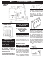
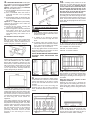
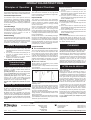
FXL(N) FAN STORAGE HEATER RANGE MODELS: FXL18N - 2.6kW / 18kWh STORAGE & 1.5kW BOOST FXL24N - 3.4kW / 24kWh STORAGE & 1.5kW BOOST INSTALLATION AND OPERATING INSTRUCTIONS IMPORTANT PLEASE READ THIS LEAFLET CAREFULLY AND RETAIN FOR FURTHER USE. NOTE ALSO THE INFORMATION GIVEN ON THE HEATER Ê The Installation must be carried out by trained personnel. Ê A means for disconnection must be incorporated in the fixed wiring by a double pole switch with a contact separation of a minimum of 3mm and in accordance with the current IEE Wiring Regulations. Ê The heater must not be installed immediately below a fixed socket outlet. Ê The heater is not suitable for connection to a 30A ring circuit. Ê Do not position the heater under windows where curtains can contact the heater casing. Ê WARNING - THE SURFACES ON THIS HEATER CAN BE HOT. Ê This heater meets EN60335 safety requirements. However, any heater type becomes hot in normal operation. Care must be taken to ensure that prolonged skin contact with the heater does not occur. Ê WHERE YOUNG CHILDREN, INFIRM PERSONS, OR THE AGED ARE PRESENT THIS APPLIANCE MUST BE ADEQUATELY GUARDED. Contact your installer or the manufacturer for further advice. Ê This appliance is very heavy and must be securely fixed to a wall. DO NOT UNDER ANY CIRCUMSTANCES ATTEMPT TO MOVE OR REPOSITION THIS HEATER WITHOUT SEEKING EXPERT ADVICE. Ê To maintain stability, it is essential that the heater is placed on a level surface. Ê This heater must be installed where it is impossible for switches and other controls to be touched by a person using a bath or shower. Ê IMPORTANT - Due to the newness of materials the heater will produce a slight smell for the first few days of operation. ROOMS MUST BE WELL VENTILATED AND YOUNG CHILDREN, CAGED BIRDS, OR PERSONS WITH RESPIRATORY COMPLAINTS MUST NOT REMAIN IN CLOSE PROXIMITY TO THE HEATER DURING THE FIRST 48 HOURS OF THE COMMISSIONING PERIOD. Ê IF, DURING ANY REASSEMBLY OF THE HEATER, A PART OF THE THERMAL INSULATION SHOWS DAMAGE OR DETERIORATION WHICH MAY IMPAIR SAFETY, IT SHOULD BE REPLACED BY AN IDENTICAL PART. INSTALLATION INSTRUCTIONS FAN/BOOST CIRCUIT 2. Remove the inner front panel by unscrewing the screws along its top and sides. As the front insulation is attached care must be taken when lifting this panel from the heater and placing it to one side. Remove the three inner guards by removing the screws along their bottom edges and sliding the guards up and off the base tray. Please note the location of each guard. STORAGE CIRCUIT WARNING - This appliance must be earthed Only heat resisting cable (min. rating T85) should be used. The wires in the mains cable will be coloured as follows:GREEN & YELLOW - EARTH BLUE - NEUTRAL BROWN - LIVE SUGGESTED FIXINGS PREPARATION The heater will arrive separately from its storage bricks, the following bricks will be required. FXL18N - 12 bricks FXL24N - 16 bricks IMPORTANT DURING NORMAL OPERATION ENSURE BOTH SUPPLIES ARE SWITCHED ON AT THE WALL. Two supplies are required for the operation of this heater - a restricted Off Peak or Economy 7 supply for the storage circuit, and an unrestricted supply for the fan boost element circuit. Thermostatic fan / boost control is provided on the heater, however the fan / boost operation may be customised by the introduction of an external timer to the heater (see section 3). SOLID BRICK/BLOCK No. 10 Rawlplug fibre inserts, 5.5mm drill bit. Drill hole 10mm deeper than rawlplug length. PLASTERBOARD If possible locate studding and use No. 10 woodscrews directly into the wood, otherwise M5 rawlplug intersets are suitable. NOTE: FOR OTHER WALL TYPES (e.g. timberframe and hollow concrete) SEEK SPECIALIST ADVICE. INSTALLATION 1. ENSURE THAT FIXING KIT HAS BEEN LOCATED BEFORE DISPOSING OF PACKAGING. Remove the front panel by removing the three screws along its bottom edge. With hands positioned on each side of the panel, lift upwards to unhook the top edge whilst pressing down on the top panel with your thumbs. The panel can now be lifted clear and set to one side. Remove the packing pieces from the slots on the inner front (3 on the FXL18N and 4 on the FXL24N). 3. CONNECTION OF THE MAINS CABLE - Connect the restricted (E7) supply to the terminal block, marked “Storage Circuit”, having first passed the cable through a front cable clamp in the base. Connect the unrestricted (Peak) supply to the terminal block, marked “Fan/Boost Circuit”, having passed this cable through another cable clamp in the base. At this point, if desired, an external fan/boost timer may be fitted to the heater by passing the two wires from the timer through the remaining cable clamp, and connecting them across the terminal block, marked “Timer”, having already removed the link fitted across this block at the factory. Connect the EARTH lead from both supplies to the terminal marked with the symbol 10. 4. FAN SPEED SELECTION - At this point the installer must choose between Normal/ High Fan or permanent High Fan option. Option 1 - The heater is factory set at Normal Fan. The fan will therefore:(a) Run at NORMAL when the boost option is not selected. (b) Run at NORMAL when the boost is selected and the core is partially depleted. (c) Automatically switch to HIGH when the boost is selected and the core is almost fully depleted. Option 2 - If a High Fan is permanently required the installer must make the following adjustment. (a) Loosen the two screws securing the wires to the resistor block. (b) Move the right wire to the left of the block and tighten both wires in the left connection point of the resistor block effectively taking the resistor out of circuit. See Fan/Boost Circuit Diagram 5. Ensure that any slack is pulled back through each clamp and tighten the clamping screws. Secure cables to base of heater using ties provided in fixing kit. Carefully fit the bottom row of the back layer of bricks placing the two end bricks into position first. Ensure that the recess in the bricks is toward the rear of the heater with the narrow end to the bottom. Repeat this with the top row of the back layer of bricks but the narrow end of the recess must be to the top. Refit the element which had been removed by feeding the tails down through the hole in the base insulation and into the connector block. Ensure the element is fully pushed home, then securely tighten the two screws in the block. 8. THE FOLLOWING MUST BE APPLIED WHEN FIXING THE HEATER TO THE WALL BRACKET. i) If no skirting board is present secure the heater through the wall bracket slots closest to the wall. ii) If 100mm (4 in.) skirting is present secure the heater through the outer slots. iii) If skirting taller that 150mm (6in.) is present this must be reduced to 150mm (6 in.) over the entire width of the heater plus 25mm (1 in.) at each end. Do not fully tighten these screws until the bricks are loaded into the heater as some settling of the heater may occur. 6. Place the heater on its feet, and in the desired position against the wall - DO NOT LIFT THE HEATER BY ITS TOP PANEL! Ensure that the heater is based on a firm level surface, at least 100mm from any end wall, and at least 100mm below any shelf or similar projection. Cut away the gripper rod or carpet which would prevent the heater sitting firmly on the floor. NOTE: NEVER REMOVE THESE SCREWS WITHOUT FIRST UNLOADING THE HEATER. 12. 9. Remove one element to allow access 7. Mark the position of the two outside corners of the wall bracket with the heater pushed tight against the wall. Remove the wall bracket from the heater by removing the screw at each end. Place the heater to one side and reposition the bracket against the wall using the corner marks for alignment. Four fixing positions must be chosen for the FXL24N and three for the FXL18N. Mark the positions for the fixing holes - two at the extreme ends and others spaced evenly between them. Remove the bracket from the wall, drill the holes in the positions marked, and insert suitable fixings previously described. Secure the wall bracket to the wall using the correct fasteners. 11. Fit the front layer of bricks with the recess toward the front of the heater. The complete core will comprise: FXL18N : 3 x 4 brick columns FXL24N : 4 x 4 brick columns for the back rows of bricks. On the FXL24N remove the element to the right of centre and on the FXL18N remove the central element. Loosen the two screws securing the element tails in the ceramic connector block, and lift the element up and out of the heater. Replace the inner front, complete with insulation, by locating its bottom edge behind the front lip of the chassis and inserting the retaining screws along the top and sides. Refit the three inner guards in their respective locations. Replace the outer front by hooking the upper grille into its retaining slot on the top panel, lower into position and replace the three self tapping screws along the bottom edge. 13. Finally, tighten the screws at each end of the wall bracket. Ensure that all screws have been tightened as this is essential to maintain earth continuity. OPERATING INSTRUCTIONS Principles of Operation Option 1 Control Functions Heat Retention Setting the Controls This storage heater takes in energy when electricity tariffs are low, and retains it in the insulated core. The controls are located at the top right hand corner of the heater, both under the hinged flap, and on the side panel. Automatic Input Control An automatic input control system varies the charge taken in response to weather conditions, taking into account the amount of energy already stored in the heater. It therefore provides an economic heating system requiring no adjustment by the user. Core Discharge A thermostatically controlled fan draws air through the hot core, releasing the stored heat as and when required, providing a level of room temperature control superior to that of conventional storage heaters. Boost Heating A supplementary direct acting element provides additional boost heating when required. Although this may function outside reduced tariff periods, the boost will only operate when the more economical ‘stored energy’ is exhausted. Safety Instructions 1. Ventilate rooms well during commissioning. 2. Do not move the heater in any way once installed without the services of a competent electrician. 3. Do not cover the heater with clothing etc. at any time, or position furniture close to, or against, the heater. 4. Ensure clearances of at least 150mm between the heater and curtains. ALSO REFER TO COVER PAGE Commissioning (first 48 hours of use) Due to the newness of materials, the heater will produce a slight smell for the first few days of operation. In order to dispel these odours as quickly as possible: (i) During the day set the input room temperature control to MAXIMUM and the boost switch to OFF, allowing the fan to run as often as possible. (ii) During the night, ensure that the boost switch is set to OFF, and reduce the room temperature control setting to MINIMUM to enable the core to accept its full charge. Ensure both supplies are switched on at the wall. Normal Use (after the first 48 hours) i) Keep both supplies switched on at the wall. ii) When only background heat is required (eg. when the room is unoccupied) set the temperature control to minimum. iii) When more heat is required in the room (eg. when the room is occupied) turn the temperature control to 5 or 6 to set the required room temperature. iv) At night time, set the temperature control back to MINIMUM, to allow the heater to accept its full charge. Input Controls This heater is fitted with a user adjustable automatic input control which varies the charge taken in response to weather conditions taking into account the amount of energy already stored in the heater. Set at 6 the heater takes a maximum charge and at 1 the heater takes a minimum charge at any room temperature. The casing of the heater, particularly in late evening, may feel cool, this is quite normal. The input control may require a few days experimentation before your comfort level is established. Initially set the control to 4, the following evening if the room is too warm reduce to 3 or if it is too cool increase to 5. On subsequent evenings adjust by half divisions until your comfort level is achieved. Having established the setting the input will automatically vary the amount of heat stored to compensate for weather conditions. Output Controls ROOM TEMPERATURE CONTROL The room temperature control will allow the fan to run until the desired room temperature has been achieved. Once this has been reached the fan will automatically cycle ON and OFF to maintain this temperature. If the room feels too warm the room temperature control should be adjusted anticlockwise; conversely if the room feels too cool it should be adjusted clockwise. BOOST OPTION Boost selection is controlled by a two position illuminated rocker switch. The boost option is only available when the fan is in operation. When the Boost is switched ON, the direct acting element will be automatically activated (in 2 stages) to supplement the heat output from a depleting core. The switch will be illuminated whenever the fan is running, although safety devices within the heater will prevent the first stage of the direct acting element (half boost) being activated until the core is partially depleted. When the core is almost fully depleted, the direct acting element will automatically switch to full power (full boost). Dependent on the option the installer has chosen (see installation instructions point 4) the fan and boost will operate as follows: (two stage fan recommended for domestic installations) If boost option is not selected Normal Fan will operate. If boost option is selected, the fan will automatically operate at Normal speed when half boost conditions apply. If boost option is selected, the fan will automatically operate at High speed when full boost conditions apply. Option 2 (single stage fan - recommended for commercial installations) If boost option is not selected High fan will operate. If the boost option is selected, the fan will automatically operate at High speed when half boost conditions apply. If the boost option is selected, the fan will automatically operate at High speed when full boost conditions apply. IMPORTANT It is recommended that the boost function be switched OFF when the heater is not in use, especially overnight when the heater is charging. During very warm weather, the fan alone may be used to circulate cool air. CLEANING To maintain the appearance of the heater, wipe occasionally with a dry cloth when the heater is cool. Do not use abrasive powders or furniture polish. Discolouration of wall finishes can sometimes occur immediately above a storage heater due to the properties of some paints and decorating materials or the presence of environmental impurities in the air (such as soot or incense generated from the burning of candles, etc). A suitable shelf (available from Dimplex) may be fitted to limit the extent of any wall discolouration. AFTER SALES SERVICE Your product is guaranteed for two years from date of purchase. Within this period, we undertake to repair or exchange this product free of charge (subject to availability) provided it has been installed and operated in accordance with these instructions. Your rights under this guarantee are additional to your statutory rights, which in turn are not affected by this guarantee. Should you require after sales service you should contact our customer services help desk on 0870 727 0101. It would assist us if you can quote the model number, series, date of purchase, and nature of the fault at the time of your call. The customer services help desk will also be able to advise you should you need to purchase any spares. Please do not return a faulty product to us in the first instance as this may result in loss or damage and delay in providing you with a satisfactory service. Please retain your receipt as proof of purchase. This appliance complies with the European Standards EN 60 335-1, EN 60 335-2-61, EN 61000-3-2, EN 61000-3-3, EN 55014 and EN55104 for Safety & Electromagnetic Compatibility. These standards cover the requirements of the EMC Directives 89/336 & 73/23. Glen Dimplex UK Limited 86926 Issue 1 : June 2006 © Glen Dimplex UK Limited. Millbrook House Grange Drive Hedge End Southampton SO30 2DF Customer Help Line Product Sales Head Office 0870 7270 101 0870 7270 103 0870 0777 117 e-mail [email protected] All rights reserved. Material contained in this publication may not be reproduced in whole or part, without prior permission in writing from Glen Dimplex UK Limited.