1
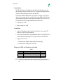
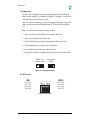
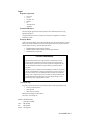
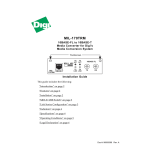
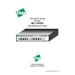
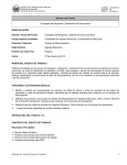
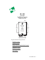
MIL-190C
Fast•Twist
Fast Ethernet Converter
Single-mode Fiber
Power
Connector
5VDC
1 Amp
FAST•TWIST
Model MIL•190
100BaseFX
to
100BaseTX
Phillips-head
Screws
Phillips-head
Screws
Fast Ethernet
CONVERTER
Single Mode Fiber
Ethernet / IEEE 802.3
POWER
FX ACTIVE
TX
TX ACTIVE
RX
SC-Type
Connector
LEDs
RJ-45
Connector
Installation Guide
This guide includes the following information:
“Introduction” on page 2
“Installation” on page 2
“Diagnostic LEDs and Conditions Indicated” on page 2
“Configuration” on page 3
“RJ-45 Pinouts” on page 3
“Legal” on page 4
Doc #: 90000072 Rev. A
Install Guide
In tro d u ctio n
The MIL-190C supports Fast Ethernet in both half- and full-duplex mode. For
network budget constraint, the MIL-190C uses 150 nanoseconds (approximately
30 meters of cable) during conversion in each direction.
To maximize the fiber cable distance, use one meter of category 5 (CAT 5) UTP
cable when connecting directly to a node (subject to fiber budget of 16 dBm and
collision domain restrictions). In full-duplex environments, up to 100 m of CAT 5
UTP and 15Km of 1300 nm single-mode fiber cable can be used:
• Launch power: -15dB
• Receive sensitivity: -31dB.
In stalla tio n
1. Attach a UTP cable from the network to the RJ-45 port. (Use screened UTP
cabling for CISPR 22 class B installation.)
2. Cross-connect the fiber cables: Attach both fiber cables TX to RX and RX to TX
from the fiber network cabling to the SC-type connector on the MIL-190C.
3. Apply power to the unit:
a. Insert the power adapter's receptacle into the power plug.
b. Insert the power adapter into a wall outlet.
D iag n o stic LEDs and Condit ions Indicat ed
Table 1:
LED
TX Active
Power
RX Active
Note:
Model: MIL-190
Condition
Color
Device is active on the 100BASE-TX UTP Yellow
Device is receiving power
Green
Device is active on the 100BASE-FX UTP Yellow
The “Active” lines indicate that a valid receive signal is sensed. Check the devices
connected to each end of the MIL-190C to ensure that Link is present at those points as
well.
2
Install Guide
C o n fi g u ra tion
The MIL-190 is configured to support auto-negotiation between half- and fullduplex modes. Jumper JP1 is configured with pins 2-3 “jumpered,” which allows
auto-negotiation between these two modes.
However, if you are connecting to a device that supports half-duplex only (or fullduplex only), then you should disable jumper JP1. Do the following to disable
JP1:
Note:
Turn off power “before” attempting to configure the device.
1. Locate and remove the four phillips screws located on the side.
2. Separate the bottom unit from the top unit.
3. Locate the JP1 Jumper and remove the jumper block from pins 2 and 3.
4. Place the jumper block onto pins 1 and 2 (See Figure 3).
5. Re-assemble the bottom back onto to the top portion.
6. Secure the unit with the four phillips-head screws that were removed earlier.
Default: Autonegotiation enabled
1
2
3
Auto-negotiation
Disabled
1
2
3
Figure 1.JP1 Configuration Options
R J-45 P in o ut s
MDI
Pin 1=TX+
Pin 2=TXPin 3=RX+
Pin 6=RX-
3 4
1 2
5 6 7 8
MDI-X
Pin 1=RX+
Pin 2=RXPin 3=TX+
Pin 6=TX-
Figure 2.RJ-45 Pinouts
Model: MIL-190
3
L eg al
Regulator y Approvals
•
•
•
•
•
FCC Class A
UL 1950
CSA 22 No. 950
EN60950
CE
– EN55022 Class B
– EN50082-1
Canadian EMI Notice
This Class A digital apparatus meets all the requirements of the Canadian Interference-Causing
Equipment Regulations.
Cet appareil numérique de la classe A respecte toutes les exigences du Règlement sur le matériel
brouilleur du Canada.
European Notice
Products with the CE Marking comply with both the EMC Directive (89/336/EEC) and the Low Voltage
Directive (73/23/EEC) issued by the commission of the European Community. Compliance with these
directives implies conformity to the following European Norms:
•
•
•
EN55022 (CISPR 22) - Radio Frequency Interference
EN50082-1 (IEC801-2, IEC801-3, IEC801-4) - Electromagnetic Immunity
EN60950 (IEC950) - Product Safety
Five-Year Limited Warranty
Digi International warrants to the original consumer or purchaser that each of its
products, and all components thereof, will be free from defects in material and/or
workmanship for a period of five years from the original factory shipment date. Any
warranty hereunder is extended to the original consumer or purchaser and is not
assignable.
Digi makes no express or implied warranties including, but not limited to, any implied
warranty of merchantability or fitness for a particular purpose, except as expressly set
forth in this warranty. In no event shall Digi be liable for incidental or consequential
damages, costs, or expenses arising out of or in connection with the performance of the
product delivered hereunder. Digi will in no case cover damages arising out of the
product being used in a negligent fashion or manner.
To Contact Digi
For prompt response when calling for service information, have the following information ready:
•
•
•
Product serial number and rev.
Date of purchase
Vendor or place of purchase
Reach Digi Technical Support at 408/744-2751
Or E-mail at “[email protected]”
Address: 1299 Orleans Drive
Sunnyvale, CA 94089
Voice:
408/744-2775
Fax:
408/744-2793
E-mail: [email protected]
Doc #: 90000072 Rev. A