1
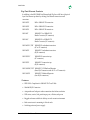
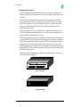
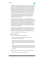
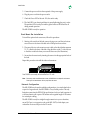
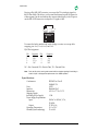
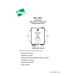
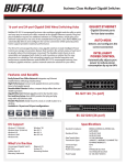
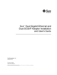
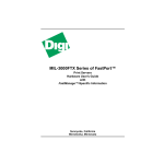
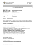
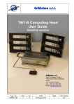
The User's Guide
for the
MIL-5008H
Fast Ethernet TX Hub
Ethernet TX Hub
1
2
3
4
MIL•5008H
II
5
Link/Rx
6
7
8
Link/Rx Power
open 2.34 x .535
Partition
Partition Collision
Digi International
Sunnyvale, California
Doc. Number: P/N 75415 Rev. C
Install Guide
Table of Contents
1. Introduction ................................................................................3
1.1 About This Guide......................................................................3
1.2 Package Contents ......................................................................3
1.3 Digi Fast Ethernet Products.....................................................4
1.4 Features.......................................................................................4
1.5 Hardware Description..............................................................4
2. Theory of Operation ..................................................................5
3. Hardware Installation ...............................................................7
3.1 Rack Mount Ear Installation....................................................7
3.2 Network Configuration............................................................8
4. Specifications ..............................................................................9
Model: MIL-5008H Fast Ethernet TX Hub
2
Install Guide
I n t ro d u c tio n
This guide describes the installation of the MIL-5008H hub and its integration into
a network. It covers unpacking the product, connection of power, cabling
requirements and connection to the RJ-45 ports, and installing the optional feet
and rack mount ears. In addition, this guide describes the meaning of the LEDs,
provides trouble shooting suggestions, and a theory of operation of the MIL5008H.
The MIL-5008H complies with the IEEE 802.3u standard for 100BASE-TX class II
hubs supporting half duplex, 100Mbps bandwidth. Each port supports auto
partitioning with reconnection after fault correction.
The LEDs easily update the user on the status of the hub. This includes collision
and power status, link integrity, data reception, and port partitioning.
A b o u t T h is Guide
This guide describes the installation of the Digi MIL-5008H Fast Ethernet
100BASE-TX hub. The guide covers the following topics:
• Description of hardware and features
• Theory of Operation
• Hardware installation procedures
• Warranty and Technical Support
Pa ck ag e Cont ent s
Carefully unpack the contents of the package and check them against the
following list:
• MIL-5008H Hub
• Power Supply
• Four rubber feet and rack mount ears
• Warranty registration card
Contact your dealer if any of the above is missing or damaged. Retain the original
shipping carton and material in the event the unit needs to be returned or
repaired.
Remember to read the enclosed warranty and return the registration card within
10 days of purchase to validate the warranty. This also entitles you to technical
support.
Model: MIL-5008H Fast Ethernet TX Hub
3
Install Guide
D ig i Fas t Et hernet Product s
In addition to the MIL-5008H Fast Ethernet hub, Digi has a full line of physical
layer Fast Ethernet products by offering Fast Ethernet transceivers and
converters.
MIL-100TX
MII to 100BASE-TX transceiver
MIL-100FX
MII to 100BASE-FX transceiver
MIL-100T4
MII to 100BASE-T4 transceiver
MIL-180T
100BASE-TX to 100BASE-FX
Media Converter (ST connector)
MIL-190C
100BASE-FX to 100BASE-TX
Media Converter (SC connector)
MIL-240FXC/FXT 100BASE-FX redundant transceiver
(SC or ST connector)
MIL-240TX
100BASE-TX redundant transceiver
(RJ-45 connector)
MIL-250FXC
100BASE-FX transceiver tap
(SC connector)
MIL-250TX
100BASE-TX transceiver tap
(RJ-45 connector)
MIL-5040FXC/FXT 100BASE-TX/FX Buffered Repeater
(three RJ-45 connectors and on SC or ST connector)
MIL-5040TX
100BASE-TX Buffered Repeater
(four RJ-45 connectors)
F e a tu re s
• IEEE 802.3u Compliant for 100BASE-TX Class II Hub
• Shielded RJ-45 Connectors
• Autopartition of bad ports and reconnection after failure resolution
• LED status, receive, link, partition per port, collision, and power
• Rugged enclosure suitable for desktop or rack mount environments
• Rack mount ears for mounting in 19 inch racks
• Switching universal power supply
Model: MIL-5008H Fast Ethernet TX Hub
4
Install Guide
H ardw are Descript ion
The MIL-5008H series hub ships with the hub, an external power supply, four
rubber feet (shipped loose) that the user may attach, and rack mount ears are also
included.
The RJ-45 connectors and LEDs are located on the front panel of the hub. The
power supply input (5VDC) is located on the rear panel. The hub is cooled by a
fan. The air intake vent is located on the left with the fan outlet located on the
right side of the unit. Care should be taken not to block these vents when
installing the MIL-5008H.
The power supply consists of a capture 5VDC, 4A cable which connects to the
hub, and a receptacle for a detached power cord. The power cord shipped with
the unit depends on the destination country.
The LEDs give status information for the hub. The Link/Receive LED has three
states, solid ON for link active and no data being received on that port, Blinking
for link active and receiving data on that port, OFF for link not detected and no
data being received. The partition LED is OFF when the port is active and ON
when the port has been partitioned. The collision light is ON when collisions are
happening, OFF when no collisions are sensed. The power LED ON indicates that
the unit is receiving power.
The RJ-45 ports are configured for connection to end node devices. Use a swap
cable to connect to another hub.
Ethernet TX Hub II
1
2
3
4
MIL•5008H
5
6
7
8
Link/Rx
Link/Rx Power
Partition
Partition Collision
open 2.34 x .535
Figure 1.Front View
Figure 2.Rear View
Model: MIL-5008H Fast Ethernet TX Hub
5
Install Guide
T h e o r y o f Operat ion
The 5008H series of hubs are 100BASE-TX, half-duplex, Class II IEEE 802.3u
compliant.
Fast Ethernet, 100BASE-X, supports three media types, fiber optics, four pair
twisted pair, and two pair twisted pair. These are known as 100BASE-FX,
100BASE-T4 and 100BASE-TX. The timing budget for 100Mbit network is 10 times
smaller than a 10Mbit network. This limits the number of Class II hubs to two and
Class I hubs to one for a single collision domain. Digi’s 5008H qualify as a class II
repeater. This means one can cascade up to two 5008H hubs to drive a total of 14
ports in a single collision domain (two ports are lost in the cascading process.
The 100BASE-TX differs from standard, 802.3 10BASE-T Ethernet in five ways:
• It communicates at 100 Mbps versus 10 Mbps.
• The collision domain span is limited to only one Class I or two Class II
repeaters, versus four repeaters for 10BASE-T.
• It requires CAT 5 two pair wiring versus CAT 3 wiring for 10BASE-T.
• It uses a new encoding mechanism known as 4B5B in MLT-3 format versus
manchester encoding.
• It uses a new attachment interface known as Media Independent Interface
(MII) versus AUI.
With the exception of a dramatic improvement in throughput, the addition of
100BASE-TX to your network is transparent to your user.
The frame format and the CSMA/CD protocol are identical between 100BASE-TX
and 10BASE-T. The ten fold improvement in bandwidth is attained by scaling the
bit rate (the rate which data is sent) by ten times. This allows you to use your
existing network software. It is up to the new hardware to take the data link
information and transmit or receive it at the 100 Mbps rate.
The ten fold increase causes a ten fold decrease in the amount of time required to
get data through the network. This decrease in time also reduces the turn around
time for sensing collisions by ten. This causes the decrease in the physical span of
the network and the limitation on the number of repeaters allowed.
The increase in speed also has the impact of requiring higher grade data cabling.
Requiring CAT 5 wiring ensures that the data will get to the other end with
minimal outside interference. For recent and new installations, this is a mute
point in that CAT 5 is a general requirement for most building codes. This
becomes an issue for older installations with CAT 3 cabling. These installations
require changing to the higher grade cabling to ensure compatibility with the
IEEE 802.3u standard.
Model: MIL-5008H Fast Ethernet TX Hub
6
Install Guide
The 4B5B encoding scheme takes four bits of data, a nibble, and maps it to a five
bit format before sending it through the network. The valid data is converted back
to 4 bits, or the control code is acted upon and removed from the stream prior to
passing the information to the receiving end. This allows for control codes to be
interspersed with data nibbles, enhancing the power of Fast Ethernet. Frames
now have begin-of-frame and end-of-frame control codes attached to them. This
will allow for future expansion when specific control codes are standardized
(except the invalid data code and the framing code). Some networking products
were developed prior to the firming up of the IEEE 100MB standard. These
devices did the 4B5B transformation prior to sending out the MII port to the
transceiver. For this reason, the Digi transceivers have the option built-in to
disable 4B5B encoding and decoding.
The new MII interface adds a tremendous amount of flexibility to the Fast
Ethernet standard. The interface allows connection of both 10Mbps and 100Mbps
technology. It also allows for multiple transceivers to be attached to one port. By
allowing up to 32 transceivers to be linked on one MII cable attached to one port,
less space is used on the workstation or network node. The Digi transceivers
come defaulted as the first transceiver, but they have dip switches which allow for
changing the address. The transceivers may be directly connected to the MII port
or may be cascaded on an MII cable.
Fast Ethernet adds more than just an improvement in speed and bandwidth to
your network. It adds future flexibility for growth. The MII port allows for adding
100Mbps devices with 10Mbps support to your existing network for future
growth. The new data encoding scheme allows for future enhancements which
will make your Ethernet network even more powerful.
H ardw are Inst allat ion
This section describes the installation of the MIL-5008H.
1. Select an appropriate location. It should be centrally located in a clean
environment with sufficient ventilation.
2. If the unit is not being rack mounted, attach the rubber feet to the bottom of
the hub, one foot approximately one half inch in from each corner. Peel the
cover of each foot to expose the adhesive backing and attach them to the MIL5008H.
3. Insert the twisted pair cables into the RJ-45 connectors. The cables should be
no longer than 100 meters with the total network span being no more than 205
meters. Digi suggests using shielded or screened Category 5, two pair, twisted
pair cabling.
Warning: Do not plug in a phone jack connector to the RJ-45 port. This may damage the hub
4. Plug the 5VDC power connector into the rear of the hub.
Model: MIL-5008H Fast Ethernet TX Hub
7
Install Guide
5. Connect the power cord into the receptacle of the power supply.
6. Plug the power cord into the power outlet.
7. Check the Power LED of the unit. If lit, the unit is ready.
8. The Link LED is on when signal detect is sensed indicating the port is active.
The partition LED for each port and the global collision LED should be off
during normal operation.
The MIL-5008H is ready for operation.
R ack Mo u nt Ear Inst allat ion
To install the optional rack mount ears, follow this procedure:
1. Starting with one side of the hub, remove the top screw, and the two bottom
screws closest to the front of the hub with a Phillips head screwdriver
2. Place one of the two rack mount ears next to hub so that the side that measures
5 1/2” is flush to the front of the hub. Align the holes on the 3” side of the ear
to the holes on the hub where you removed the screws (See Illustration).
3. Secure the rack mount ear by inserting the screws into the appropriate holes of
the hub.
Repeat this procedure to install the other rack mount ear.
Ethernet TX Hub II
1
2
3
4
MIL•5008H
5
6
7
8
Link/Rx
Link/Rx Power
Partition
Partition Collision
open 2.34 x .535
Your 5008H is now ready to be installed in a 19” rack.
Note:
Since many racks use different size screws, the 5008H does not ship with rack screws.
Check your rack manufacturer for the proper size rack screw.
N etwo rk Configurat ion
The MIL-5008H may be used in multiple configurations. As a stand alone hub or
as part of a larger network, the MIL-5008H is a very flexible product. The only
limitation comes from the IEEE 802.3u specification of only two hubs/repeaters in
a collision domain with a span of 205 meters and a segment length of 100 meters
for twisted pair cabling.
The MIL-5008H is ready for straight through connection to your workstation,
server RJ-45 port, or a transceiver such as the MIL-100TX, which adapts your
workstation or servers MII port to the TX media.
Model: MIL-5008H Fast Ethernet TX Hub
8
Install Guide
By using a Digi MIL-180T converter, you convert the TX twisted pair signals to
the FX fiber media. This allows you to extend the distance beyond 100 meters for
a fiber segment. On the workstation side, connect either directly to the FX port or
use the MIL-100FX transceiver to adapt the FX signals to MII.
3 4
1 2
5 6 7 8
To connect the hub to another hub, switch, bridge or router, use a swap cable
swapping pins 1 to 3, 2 to 6, 6 to 2, and 3 to 1.
RJ-45 Pin Assignment
Pin
1
2
3
4
Function
RX +
RX TX +
NC
Pin
5
6
7
8
Function
NC
TX NC
NC
NC = Not Connected, RX = Receive Data, TX = Transmit Data
Note:
Don’t use NC pins for covering other network traffic or telephone signaling if the building is
wired for 8 pins. It will degrade the performance of the 100MB operation.
S p ec ifi ca tions
Conformance
Ports
Interface
Dimensions
Shipping Weight
(including Power Supply)
Power Supply Requirements
Input
Output
Operating Temperature
Humidity (noncondensing)
Model: MIL-5008H Fast Ethernet TX Hub
IEEE 802.3u Class-II
100BASE-TX
8 UTP
Shielded RJ-45
8.4" W x 1.7" H x 5.1" D
1.5 lb.
100VAC to 240VAC, 0.7A,
50/60Hz
5V DC, 4.0A
0° C to 50° C
5% to 90%
9
L eg al
Regulator y Approvals
•
•
•
•
•
FCC Class A
UL 1950
CSA 22 No. 950
EN60950
CE
– EN55022 Class B
– EN50082-1
Canadian EMI Notice
This Class A digital apparatus meets all the requirements of the Canadian Interference-Causing
Equipment Regulations.
Cet appareil numérique de la classe A respecte toutes les exigences du Règlement sur le matériel
brouilleur du Canada.
European Notice
Products with the CE Marking comply with both the EMC Directive (89/336/EEC) and the Low Voltage
Directive (73/23/EEC) issued by the commission of the European Community. Compliance with these
directives implies conformity to the following European Norms:
•
•
•
EN55022 (CISPR 22) - Radio Frequency Interference
EN50082-1 (IEC801-2, IEC801-3, IEC801-4) - Electromagnetic Immunity
EN60950 (IEC950) - Product Safety
Five-Year Limited Warranty
Digi International warrants to the original consumer or purchaser that each of its
products, and all components thereof, will be free from defects in material and/or
workmanship for a period of five years from the original factory shipment date. Any
warranty hereunder is extended to the original consumer or purchaser and is not
assignable.
Digi makes no express or implied warranties including, but not limited to, any implied
warranty of merchantability or fitness for a particular purpose, except as expressly set
forth in this warranty. In no event shall Digi be liable for incidental or consequential
damages, costs, or expenses arising out of or in connection with the performance of the
product delivered hereunder. Digi will in no case cover damages arising out of the
product being used in a negligent fashion or manner.
To Contact Digi
For prompt response when calling for service information, have the following information ready:
•
•
•
Product serial number and rev.
Date of purchase
Vendor or place of purchase
Reach Digi Technical Support at 408/744-2751
Or E-mail at “[email protected]”
Address: 1299 Orleans Drive
Sunnyvale, CA 94089
Voice:
408/744-2775
Fax:
408/744-2793
E-mail: [email protected]
Doc. Number: P/N 75415 Rev. C