1
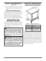
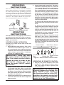
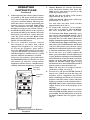
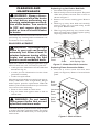
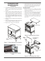
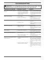
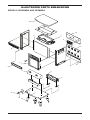
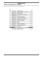
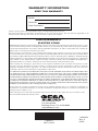
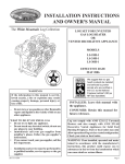
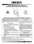
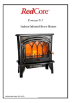
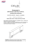
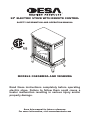
20" ELECTRIC STOVE WITH REMOTE CONTROL
SAFETY INFORMATION AND OPERATION MANUAL
Models CGESBMRA AND VESBMRA
Read these instructions completely before operating
electric stove. Failure to follow them could cause a
heater malfunction resulting in serious injury and/or
property damage.
Save this manual for future reference.
For more information, visit www.desatech.com
Table of Contents
Safety Information................................................ 2
Listing Approvals.................................................. 3
Unpacking and Testing the Unit............................ 3
Product Dimensions & Specifications................... 3
Grounding instructions......................................... 4
Operating Instructions.......................................... 4
Cleaning and Maintenance................................... 6
Technical Service................................................. 8
Replacement Parts............................................... 8
Troubleshooting.................................................... 9
Illustrated Parts Breakdown and Parts List........ 10
Warranty Information............................Back Cover
Safety Information
WARNING: Improper installation, adjustment, alteration, service or maintenance can cause
injury or property damage. Refer
to this manual. For assistance or
additional information, consult
a qualified installer.
WARNING: Risk of fire. Keep
combustible material away from
the front of the heater. Keep electrical cords, drapery and other
furnishings at least 3 feet from the
front and sides of electric stove.
WARNING: Servicing should
be done only while the heater
is disconnected from the power
supply circuit.
CAUTION: For lower lamps
(ember bed) and flame generation
lamps, replace only with lamp type
GX6.35 rated 120V, 35W max. For
upper lamps (top contrasting light)
replace only with lamp type GX6.35,
rated 120V , 20W max.
Your electric stove is classified as an electric
heater. As with any electrical appliance and particularly with electric heaters, basic precautions
must be followed in order to reduce the risk of
fire, burns, electrical shocks and/or other serious
injuries or death.
1. Read all instructions before using this heater.
2. The unit can become hot when in use. To avoid
accidental burns, do not allow skin to come into
contact with the hot surfaces of the unit. Keep
children and pets away from unit when in use.
3. Keep combustible materials, such as furniture,
pillows, bedding, papers, clothes and curtains
at least 3 feet from heater. Do not use this unit
in areas where gasoline, paint or other flammable liquids or vapors may be present.
4. Do not use this unit for drying wet clothes.
5. Do not operate unit if it is damaged or has malfunctioned. If you suspect the unit is damaged,
return it to an authorized service facility for
examination, electrical or mechanical adjustment or repair.
6. Do not use this unit outdoors.
7. Do not use or install this unit in areas prone to
dampness or where it may come into contact
with water. This heater is not intended for use
in bathrooms, laundry areas or other locations
where water may be present.
8. To reduce the risk of fire, do not place or
install this unit in areas where the ventilation
or circulation ducts may become blocked.
9. Do not insert or allow foreign objects to enter
any of the ventilation or circulation ducts as
this may cause electric shock, fire or otherwise
damage the unit.
10. The unit's power supply cord must be connected to a properly grounded and protected,
120-volt electrical outlet. Always use ground
fault protection where required by the electrical code. To reduce the risk of fire, avoid running power supply cord under rugs, carpets,
etc. Keep the power supply cord away from
high traffic area where it may pose a tripping
hazard.
11. Avoid the use of an extension cord because
the extension cord may overheat and cause
a risk of fire. However, if you have to use an
extension cord, the cord should be No. 14
AWG minimum size with a grounding plug
and rated not less than 1875 WATTS.
12. Always disconnect the unit from the power
supply before performing any cleaning, light
bulb replacement, maintenance, relocating the
heater or when the unit is not in use for long
periods of time.
www.desatech.com
119668-01A
SAFETY INFORMATION
Continued
13. When transporting or storing the unit, keep
it in a dry location, free from dust, excessive
vibration or other factors, which may damage
the unit.
Product Dimensions
and Specifications
12.5"
20"
Listing Approvals
This heater has been tested in accordance with the
CSA Standards for fixed and location-dedicated
electric room heaters in the United States. All
components are UL or CSA safety certified.
If you need assistance during installation, please contact your local dealer or the DESA Heating Products
Technical Services Department at 1-866-672-6040.
25.25"
Unpacking and
Testing the Unit
Carefully remove the unit from the box. Prior to
permanently installing the unit, test to make sure
the unit operates properly by plugging the power
supply cord into a conveniently located 120-volt
grounded outlet.
CAUTION: The unit's power
supply cord must be connected
to a properly grounded and protected 120-volt outlet. Always
use ground fault protection
where required by the electrical code.
WARNING: Do not operate
the unit if it is damaged or has
malfunctioned. If you suspect the
unit is damaged, return the unit
to an authorized service facility
for examination, electrical or mechanical adjustment or repair.
119668-01A
Figure 1 - Heater Dimensions
Frequency
Heater Power
Heater Output
Power Supply
60 Hz
1500 W
5000 BTUs
120V; 15 Amp
Grounded, Circuit
Note: A dedicated power supply circuit is recommended for the unit but not required. Additional
electrical appliances on the same circuit may exceed the current (amperage) rating for that circuit.
If after the installation of your unit, the circuit
breaker trips or the fuse fails on a repeated basis,
then a dedicated circuit will likely be required. Any
new wiring must be done in compliance with local
and national codes and other applicable regulations in order to reduce the risk of fire, electric
shock or other injuries. Therefore, it is strongly
recommended that you hire a licensed electrician
to complete any such work.
www.desatech.com
Grounding
instructions
This stove is for use on 120 volts. The cord has a
plug as shown in Figure 2. An adapter is available
for connecting three-blade grounding-type plugs
to two-slot receptacles. The green grounding plug
extending from the adapter must be connected to
a permanent ground such as a properly grounded
outlet box. The adapter should not be used if a
three-slot grounded receptacle is available.
Adapter
Grounding Pin
Figure 2 - Grounding Methods
Operating
Instructions
Once the unit has been properly connected to a
ground electrical outlet, it is ready to operate.
Note: Ensure the circuit breakers for power
supply are turned on.
Control Panel Operation
Controls are located on the back of the unit
(see Figure 3).
1. Main ON/OFF Power Switch: This switch
is located at the furthest right corner on
the control panel when looking at the back
of the unit. Turn the switch to ON and unit
will be ready to operate. The "|" indicates
ON and "O" indicates OFF.
IMPORTANT: Once you turn
the main switch to the ON position, the remote control can no
longer be used. In order to use
the remote control, you must
keep the main ON/OFF switch
in the OFF.
2. Ember Control Dial: There is a divided
circle under this dial. After you turn the
Main Power switch to the ON position, turn
the Ember Control Dial to desired setting.
This dial controls the intensity of the lighting under the ember bed.
3. Flame Control Dial: There is a flame picture
under this dial. Turn this dial to adjust the
flame intensity.
4. Heater Switch and Control Dial: The heater
switch has a sun directly below it. To turn the
heater on, flip Heater Switch to ON position
( "|" indicates ON and "O" indicates OFF).
The Control Dial has a thermometer below it.
Turn dial clockwise past the number 8. You
should hear a small clicking sound indicating the heater has started and heat will emit
through vents located at the top of unit. To turn
off heater, turn the temperature dial counter
clockwise past number 1 and flip Heater
Switch to OFF position.
To increase the desired temperature, turn
temperature dial clockwise towards Number 8.
To decrease desired temperature, turn
temperature dial counter clockwise towards
number 1. The heater has a built-in thermostat so it will shut off automatically once set
temperature is reached. It will also turn on
automatically if room temperature drops
below the set temperature on dial.
Note: When the heater is turned on for the
first time, it may release a slight, harmless
odor. This odor is a normal occurrence caused
by the initial heating of the internal heating
elements and should not occur again. (Some
odor may occur when dust settles on the unit
and is burned off).
Heater Switch
Main Power Switch
Flame
Ember Control
Control Dial Dial
Figure 3 - Electric Stove Control Panel
Heat Control
Dial
Operating by remote control
1. Plug in your electric fireplace and it will
beep once. This means you have power
and your remote is ready to operate your
electric fireplace.
IMPORTANT: To control the
electric fireplace by remote, the
Main ON/OFF power switch on
the fireplace must be in the OFF
position; the remote control will
NOT work if the manual ON/OFF
switch is in the ON position.
www.desatech.com
119668-01A
Operating
Instructions
Continued
2. When operating the remote control, it must
be pointed at the logset inside the electric
stove and a beep must be heard each time
you press a function button. The beep confirms the remote control is performing the
function you have requested. Note: Make
sure your batteries are fully charged and
installed correctly in your remote control.
3. POWER ON/OFF button at the top left is
the main ON/OFF power button. Pressing
this button you will hear a beep; this activates the power to the unit. Note: If the
flame does not come immediately, press the
DISPLAY ON/OFF button.
4. The two LOGSET buttons control
the brightness of ember bed, which
changes the brightness of your logset.
To increase the brightness, press and release the BRIGHTER button. Each time
you press this button you will hear a beep,
and the brightness will increase by a small
amount, until the maximum is reached.
To decrease the brightness, press and release
the DIMMER button. Each time you press
this button you will hear a beep and the
brightness will decrease by a small amount,
until the minimum brightness is reached.
Infrared
Ray Exit
POWER
Indicator
Light
ON/OFF
DISPLAY
Dimmer
ON/OFF
Brighter
EMBERS/
LOGSET
HEATER
ON/OFF
TEMP. CONTROL
HIGH
MED
FLAME
LOWER
LOW
HIGHER
5. Heater Button: To activate the heater,
press the heater button, then press HI,
MED or LO. The heater is pre-set to the
following temperatures:
HIGH will shut off when room reaches
approximately 86° F (30° C)
MED will shut off when room reaches approximately 75° F (24° C)
LO will shut off when room reaches
approximately 64° F (18° C)
6. To adjust the intensity of the flame,
press the two buttons labeled HIGHER and LOWER under FLAME.
To increase the flame intensity, press
and release the HIGHER button. Each
time you press the button you will hear a
beep and the size of the flame will increase
slightly until the maximum setting is reached.
To decrease the flame intensity, press
and release the LOWER button. Each time
you press this button you will hear a beep
and the size of the flame will decrease slightly until the minimum setting is reached.
7. To use the stove as a heater without the
flame, press the DISPLAY ON/OFF button
to turn the flame off and press the HEATER
ON/OFF button to turn the heater on (if the
heater was in the OFF position). Press the
DISPLAY ON/OFF button again to turn
the flame back on. Press HEATER ON/OFF
button again to turn the heater off.
Note: You may have to readjust your desired flame setting (see step 6).
8. To turn stove off, press POWER ON/OFF
button once. When you hear the beep, the
fireplace will be completely off and the
flame will disappear. When you restart the
fireplace with the remote control, all of the
features you had set will remain in effect.
NOTICE: This remote control must remain
within 26 feet (8 m) of the fireplace to be
effective.
IMPORTANT: If flame does not activate
after POWER ON/OFF button is pressed,
press DISPLAY ON/OFF button to activate
the flame. If flame does not appear, repeat
step 4.
Figure 4 - Remote Control For Electric
Fireplace
119668-01A
www.desatech.com
Cleaning and
Maintenance
WARNING: Always disconnect power and allow the heater
to cool before performing any
cleaning, maintenance or relocation of this heater. Turn controls
to OFF and remove plug from
outlet or turn off circuit breaker
to heater.
Turn off heater and circuit breaker to heater before
performing any cleaning and/or maintenance. Allow heater to cool completely.
Bulb Replacement
WARNING: The halogen light
bulbs in your unit can become
extremely hot. Allow at least 10
minutes between turning off the
heater and removing the light
bulbs to avoid accidental burns.
There are a total of 5 ( halogen light bulbs (type
GX6.35 rated 120 volts, 35 watts) in your unit.
• 1 bulb provides illumination for the ember bed
beneath the log set
• 2 bulbs provide illumination for the flame
generation assembly
• 2 bulbs for replacement
Most halogen light bulbs are rated to last approximately 1800 hours. Like all light bulbs, halogen
bulbs require periodic replacement. When the
bulbs in your unit have burned out you will notice
one or more of the following:
• Flame is dim or dark in certain areas
• Log set ember bed appears dim or dark in
certain areas
WARNING: Do not install
replacement bulbs that exceed
specified maximum watts.
Replacing Log Set Ember Bed Bulb
1. Turn knob and open door of stove.
2. Push in and up on lower front panel. The panel
slides into notches on front sides of stove as
shown in Figure 5.
3. Remove two screws securing grate. Remove
grate.
4. Hold log up away from bulb and carefully
remove spring clip over bulb using needle
nose pliers. Remove bulb.
5. With log being held up away from socket,
insert new bulb and carefully replace spring
clip using needle nose pliers.
Log
Lower Front
Panel
Grate
Figure 5 - Ember Bed Bulb Location
Replacing Flame Generation Bulbs
1. Unscrew 4 screws from louvered back
panel (see Figure 6). Remove louvered back
panel.
Back
Control
Panel
Louvered
Back
Panel
Lower
Back
Panel
Your unit must be opened from the back in order
to replace the flame generation bulbs. To replace
the bulb under the ember bed you will open the
unit in front.
Bulb in Socket
with Spring Clip
www.desatech.com
Figure 6 - Back of Stove
119668-01A
Cleaning and
Maintenance
Continued
2. Locate flame generation cylindrical drum (see
Figure 7). It is constructed of two removable
halves; either of which can be removed from
the unit.
3. Squeeze half of drum cylinder until it's top
edge clears the top drum track (see Figure 8).
Remove bottom edge of cylinder drum from
bottom drum track. This will give you access
to the light bulbs. Note: Do not exert excessive pressure on drum cylinder as this may
cause damage.
4. Remove spring clip. Hold socket and pull out
old bulb.
5. Hold socket and push in new bulb (DO NOT
exceed wattage). Replace spring clip.
6. Repeat steps 3 and 4 for second bulb.
7. Insert bottom edge of removed cylinder half into
bottom drum track. Gently squeeze drum cylinder until it's top edge fits into top drum rack.
8. Replace louvered back panel.
Replacing Glass
1. Remove top of stove by sliding top toward
the back (see Figure 9). Top fits into slots and
should slide off easily.
2. Remove four screws securing back control panel
(see Figure 10). DO NOT STRESS WIRES.
3. Remove four screws securing heater/blower
assembly to stove assembly (see Figure 10).
Assembly must be held securely while removing screws.
Top of Stove
Figure 9 - Removing Top of Stove
Glass
Panel
Flame Cylinder
Drum
Heater/Blower
Assembly
Figure 7 - Flame Cylinder Drum Location
Flame
Cylinder Drum
Back Control
Panel
Figure 8 - Flame Generation Cylinder
Drum
Figure 10 - Removing Glass Panel
119668-01A
www.desatech.com
Cleaning and
Maintenance
Continued
4. Slide heater assembly out back of stove and
set aside (see Figure 10, page 7).
5. Slide glass up through top of stove.
6. Slide new glass into place between glass
retainers.
7. Replace heater/blower assembly using screws
removed in step 3, page 7.
8. Replace back control panel using screws
removed in step 2, page 7.
9. Slide top of stove back into slots.
Replacing Log
1. Follow steps 1 through 4 under Replacing
Glass, page 7, to allow access to log.
2. Carefully pull up on log to remove from stove
cavity.
3. Place replacement log into stove.
4. Follow steps 5 through 8 under Replacing
Glass to complete this procedure.
Cleaning Front panel glass
WARNING: When cleaning
unit, the power supply should
be disconnected and the unit
should be cool.
Over time the front glass panel may become dirty or
dusty. Dust can be removed by lightly rubbing the
glass surface with a clean, lint free cloth or paper
towel. To remove fingerprints or other marks, use
a damp cloth with a good quality household glass
cleaner. The front glass panel should be completely
dried with a clean, lint free cloth or paper towel.
CAUTION: Do not use abrasive cleaners on glass panel. Do
not spray liquids directly onto
any surface of the unit.
Storage
When not in use, unplug the unit from the power
supply and store in dry, dust free location.
Technical Service
You may have further questions about your electric stove. If so, contact DESA Heating Products’
Technical Service Department at 1-866-672-6040.
When calling please have your model and serial
numbers of your heater ready.
You can also visit DESA Heating Products’ technical services web site at www.desatech.com.
Replacement Parts
Note: Use only original replacement parts. This
will protect your warranty coverage for parts
replaced under warranty.
Parts Under Warranty
Contact authorized dealers of this product. If
they can’t supply original replacement part(s),
call DESA Heating Products’ Technical Service
Department at 1-866-672-6040.
When calling DESA Heating Products, have ready
• your name
• your address
• model and serial numbers of your heater
• how heater was malfunctioning
• purchase date
Usually, we will ask you to return the part to the
factory.
Parts Not Under Warranty
Contact authorized dealers of this product. If they
can’t supply original replacement part(s), call
DESA Heating Products at 1-866-672-6040 for
referral information.
When calling DESA Heating Products, have ready
• model number of your heater
• the replacement part number
WARNING: An authorized
service representative should
perform any other servicing.
www.desatech.com
119668-01A
Troubleshooting
WARNING: Turn off appliance and let cool before servicing. Only
a qualified service person should service and repair heater.
OBSERVED PROBLEM
POSSIBLE CAUSE
REMEDY
Stove turns off and will not
turn on
1. Stove has overheated and safety devise has cause thermal
switch to disconnect, home
circuit breaker has opened or
fuse has blown
1. Reset switch by turning main
power switch off and waiting
5 minutes then turning it back
on, reset home circuit breaker
or replace fuse
Flame is not moving
1. Loose wiring
1. Inspect wiring for loose connections
2. Call a qualified service technician to replace flame motor
2. Flame motor defective
Dim or poorly visible flame
1. Bulb(s) are burnt out
2. Wiring is loose
1. Inspect bulbs and replace if
necessary
2. Inspect wiring for loose connections and repair or replace
if necessary
Ember is not glowing
1. Bulb is burnt out
2. Wiring is loose
1. Replace bulb
2. Inspect wiring for loose connections and repair or replace
if necessary
Flame sputters
1. Flame motor is defective
1. Call a qualified service technician to replace flame motor
Remote control does not work
1. Low batteries
1. Replace AA batteries in remote control
2. Turn off main power switch
(see Figure 3, page 4)
2. Unit switch and/or wall
switch in ON position
Heater does not provide heat
when turned on
1. Thermal switch has been
tripped
2. Circuit breaker has been
tripped or fuse has blown
119668-01A
www.desatech.com
1. Turn unit off and unplug
unit for 5 minutes. Plug back
in and turn unit on. If plug
cannot be reached, follow
directions for tripped circuit
breaker
2. Turn off circuit breaker that
supplies electricity to unit.
Wait 5 minutes then flip circuit
breaker back on or replace
fuse
Illustrated Parts Breakdown
Models CGESBMRA AND VESBMRA
16
13
6
1
2
14
8
7
15
9
5
3
4
11
10
12
10
www.desatech.com
119668-01A
PARTS LIST
Models CGESBMRA AND VESBMRA
This list contains replaceable parts used in your fireplace. When ordering parts, follow the instructions
listed under Replacement Parts on page 8 of this manual.
KEY
NO.
PART NO.
DESCRIPTION
1
2
3
4
5
6
7
8
9
10
11
12
13
14
15
16
117708-01
119672-01
117697-01
117696-01
117690-01
117704-01
119663-01
119666-01
119665-01
117754-01
117695-01
117706-01
119669-01
119670-01
119671-01
117705-01
Blower and Heater Assembly
Control Board
Flame Motor
Flame Cylinder Assembly
Log
Rear Glass (Mirror)
Front Door Assembly
Heater Vent Front Panel
Bottom Front Panel
Light Bulb Sockets
Bulb
Legs
Back Control Panel
Back Louvered Panel
Lower Back Panel
Stove Top
QTY.
1
1
1
1
1
1
1
1
1
2
3
4
1
1
1
1
PARTS AVAILABLE — NOT SHOWN
117732-01
111401-01
119668-01A
Remote Control
Batteries (AA)
www.desatech.com
1
2
11
Warranty Information
KEEP THIS WARRANTY
Model
Serial No.
Date Purchased
Always specify model and serial numbers when communicating with the factory.
We reserve the right to amend these specifications at any time without notice. The only warranty applicable is our
standard written warranty. We make no other warranty, expressed or implied.
LIMITED WARRANTY
ELECTRIC STOVE
DESA Heating Products warrants this product to be free from defects in materials and components for one (1) year
from the date of first purchase (excluding bulbs and fuses), provided that the product has been properly installed,
operated and maintained in accordance with all applicable instructions. To make a claim under this warranty the
Bill of Sale or cancelled check must be presented.
This warranty is extended only to the original retail purchaser. This warranty covers the cost of part(s) required
to restore this heater to proper operating condition (excluding bulbs and fuses) and an allowance for labor when
provided by a DESA Heating Products Authorized Service Center. Warranty part(s) MUST be obtained through
authorized dealers of this product and/or DESA Heating Products who will provide original factory replacement
parts. Failure to use original factory replacement parts voids this warranty. The heater MUST be installed by a
qualified installer in accordance with all local codes and instructions furnished with the unit.
This warranty does not apply to parts that are not in original condition because of normal wear and tear or parts
that fail or become damaged as a result of misuse, accidents, lack of proper maintenance or defects caused by
improper installation. Travel, diagnostic cost, labor, transportation and any and all such other costs related to
repairing a defective heater will be the responsibility of the owner.
TO THE FULL EXTENT ALLOWED BY THE LAW OF THE JURISDICTION THAT GOVERNS THE SALE
OF THE PRODUCT; THIS EXPRESS WARRANTY EXCLUDES ANY AND ALL OTHER EXPRESSED
WARRANTIES AND LIMITS THE DURATION OF ANY AND ALL IMPLIED WARRANTIES, INCLUDING
WARRANTIES OF MERCHANTABILITY AND FITNESS FOR A PARTICULAR PURPOSE TO ONE (1) YEAR
ON ALL COMPONENTS FROM THE DATE OF FIRST PURCHASE; AND DESA HEATING PRODUCTS’
LIABILITY IS HEREBY LIMITED TO THE PURCHASE PRICE OF THE PRODUCT AND DESA Heating Products SHALL NOT BE LIABLE FOR ANY OTHER DAMAGES WHATSOEVER INCLUDING
INDIRECT, INCIDENTAL OR CONSEQUENTIAL DAMAGES.
Some states do not allow a limitation on how long an implied warranty lasts or an exclusion or limitation of
incidental or consequential damages, so the above limitation on implied warranties or exclusion or limitation on
damages may not apply to you.
This warranty gives you specific legal rights and you may also have other rights that vary from state to state.
For information about this warranty write:
2701 Industrial Drive
P.O. Box 90004
Bowling Green, KY 42102-9004
www.desatech.com
119668 01
NOT A UPC
119668-01
Rev. A
06/06