1
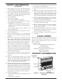
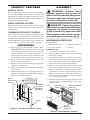
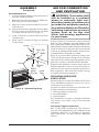
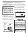
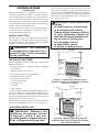
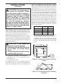
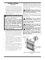
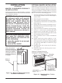
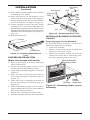
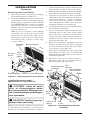
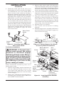
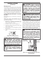
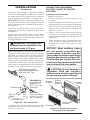
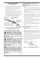
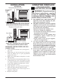
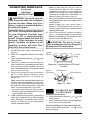
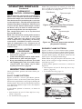
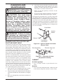
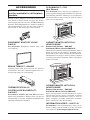
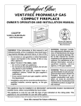
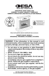
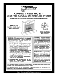
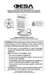
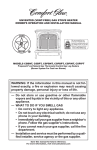
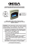
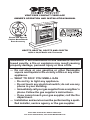
VENT-FREE COMPACT FIREPLACE
OWNER’S OPERATION AND INSTALLATION MANUAL
Shown with Optional
Cabinet Mantel/Hearth
Base Accessory
HDCFTP, HDCFTN, CGCFTP AND CGCFTN
14,000 to 26,000 Btu/Hr with Thermostat
WARNING: If the information in this manual is not followed exactly, a fire or explosion may result causing
property damage, personal injury or loss of life.
— Do not store or use gasoline or other flammable
vapors and liquids in the vicinity of this or any other
appliance.
— WHAT TO DO IF YOU SMELL GAS
• Do not try to light any appliance.
• Do not touch any electrical switch; do not use any
phone in your building.
• Immediately call your gas supplier from a neighbor’s
phone. Follow the gas supplier’s instructions.
• If you cannot reach your gas supplier, call the fire
department.
— Installation and service must be performed by a qualified installer, service agency or the gas supplier.
Save this manual for future reference.
For more information, visit www.desatech.com
WARNING: Improper installation, adjustment, alteration, service or maintenance can cause injury or property damage. Refer to this manual for correct installation
and operational procedures. For assistance or additional information consult a qualified installer, service
agency or the gas supplier.
WARNING: This is an unvented gas-fired heater. It uses
air (oxygen) from the room in which it is installed. Provisions for adequate combustion and ventilation air must
be provided. Refer to Air for Combustion and Ventilation
section on page 6 of this manual.
This appliance may be installed in an aftermarket,* permanently located, manufactured (mobile) home, where
not prohibited by local codes.
This appliance is only for use with the type of gas indicated on the rating plate. This appliance is not convertible for use with other gases.
* Aftermarket: Completion of sale, not for purpose of resale, from the manufacturer
State of Massachusetts: The installation must be made by a licensed plumber or gas fitter in the
Commonwealth of Massachusetts.
Sellers of unvented propane or natural gas-fired supplemental room heaters shall provide to each
purchaser a copy of 527 CMR 30 upon sale of the unit.
Vent-free gas products are prohibited for bedroom and bathroom installation in the Commonwealth of Massachusetts.
TABLE OF CONTENTS
Safety Information ............................................... 3
Local Codes ........................................................ 4
Product Information ............................................. 4
Product Features ................................................. 5
Unpacking ........................................................... 5
Assembly ............................................................. 5
Air For Combustion and Ventilation ..................... 6
Installation ........................................................... 8
Operating Fireplace ........................................... 19
Inspecting Burner .............................................. 21
2
Cleaning and Maintenance ................................ 22
Troubleshooting ................................................. 23
Specifications .................................................... 27
Replacement Parts ............................................ 27
Service Hints ..................................................... 27
Technical Service .............................................. 27
Illustrated Parts Breakdown and Parts List ....... 28
Accessories ....................................................... 30
Parts Centrals .................................................... 31
Warranty Information ............................ Back Page
www.desatech.com
111044-01F
SAFETY INFORMATION
WARNING: This product contains and/or generates chemicals
known to the state of California
to cause cancer or birth defects
or other reproductive harm.
IMPORTANT: Read this owner’s
manual carefully and completely
before trying to assemble, operate or service this fireplace.
Improper use of this fireplace
can cause serious injury or
death from burns, fire, explosion, electrical shock and carbon
monoxide poisoning.
DANGER: Carbon monoxide
poisoning may lead to death!
Carbon Monoxide Poisoning: Early signs of carbon
monoxide poisoning resemble the flu, with headaches, dizziness or nausea. If you have these signs,
the heater may not be working properly. Get fresh
air at once! Have fireplace serviced. Some people
are more affected by carbon monoxide than others.
These include pregnant women, people with heart
or lung disease or anemia, those under the influence
of alcohol and those at high altitudes.
Natural and Propane/LP Gas: Natural and propane/LP gases are odorless. An odor-making agent
is added to the gas. The odor helps you detect a gas
leak. However, the odor added to the gas can fade.
Gas may be present even though no odor exists.
Make certain you read and understand all warnings.
Keep this manual for reference. It is your guide to
safe and proper operation of this fireplace.
WARNING: Any change to
this fireplace or its controls can
be dangerous.
WARNING: Do not use a blower insert, heat exchanger insert
or other accessory not approved
for use with this fireplace.
Due to high temperatures, the
appliance should be located out
of traffic and away from furniture
and draperies.
Do not place clothing or other
flammable material on or near
the appliance. Never place any
objects on the heater.
Fireplace front and screen becomes very hot when running
fireplace. Keep children and
adults away from hot surfaces to
avoid burns or clothing ignition.
Fireplace will remain hot for a
time after shutdown. Allow surfaces to cool before touching.
Carefully supervise young children when they are in the room
with fireplace.
You must operate this fireplace with the fireplace screen
in place. Make sure fireplace
screen is closed before running
fireplace.
Keep the appliance area clear
and free from combustible materials, gasoline and other flammable vapors and liquids.
WARNING: Do not allow fans
to blow directly into the fireplace.
Avoid any drafts that alter burner
flame patterns. Ceiling fans can
create drafts that alter burner
flame patterns. Altered burner
patterns can cause sooting.
111044-01F
www.desatech.com
3
SAFETY INFORMATION
Continued
1. This appliance is only for use with the type of
gas indicated on the rating plate. This appliance
is not convertible for use with other gases.
2. Do not place propane/LP supply tank(s) inside
any structure. Locate propane/LP supply tank(s)
outdoors (propane/LP units only).
3. If you smell gas
• shut off gas supply
• do not try to light any appliance
• do not touch any electrical switch; do not use
any phone in your building
• immediately call your gas supplier from a
neighborʼs phone. Follow the gas supplierʼs
instructions
• if you cannot reach your gas supplier, call
the fire department
4. This fireplace shall not be installed in a bedroom or bathroom.
5. Do not use this fireplace as a wood-burning
fireplace. Use only the logs provided with the
fireplace.
6. Do not add extra logs or ornaments such as
pine cones, vermiculite or rock wool. Using
these added items can cause sooting. Do not
add lava rock around base. Rock and debris
could fall into the control area of fireplace.
7. This fireplace is designed to be smokeless. If
logs ever appear to smoke, turn off fireplace
and call a qualified service person. Note:
During initial operation, slight smoking could
occur due to log curing and fireplace burning
manufacturing residues.
8. To prevent the creation of soot, follow the
instructions in Cleaning and Maintenance,
page 22.
9. Before using furniture polish, wax, carpet
cleaner or similar products, turn heater off. If
heated, the vapors from these products may
create a white powder residue within burner
box or on adjacent walls or furniture.
10. This fireplace needs fresh air ventilation to run
properly. This fireplace has an Oxygen Depletion Sensing (ODS) safety shutoff system. The
ODS shuts down the fireplace if not enough
fresh air is available. See Air for Combustion
and Ventilation, page 6. If fireplace keeps
shutting off, see Troubleshooting, page 23.
11. Do not run fireplace
• where flammable liquids or vapors are used
or stored.
• under dusty conditions.
4
12. Do not use this fireplace to cook food or
burn paper or other objects.
13. Never place any objects in the fireplace or on
logs.
14. Do not use fireplace if any part has been under
water. Immediately call a qualified service
technician to inspect the room fireplace and
to replace any part of the control system and
any gas control which has been under water.
15. Turn off and unplug fireplace and let cool before servicing. Only a qualified service person
should service and repair fireplace.
16. Operating fireplace above elevations of 4,500
feet could cause pilot outage.
17. Do not operate fireplace if any log is broken.
Do not operate fireplace if a log is chipped
(dime-sized or larger).
18. To prevent performance problems, do not use
propane/LP fuel tank of less than 100 lbs.
capacity (propane/LP units only).
19. Provide adequate clearances around air
openings.
LOCAL CODES
Install and use fireplace with care. Follow all local
codes. In the absence of local codes, use the latest
edition of The National Fuel Gas Code ANSI
Z223.1/NFPA 54*.
*Available from:
American National Standards Institute, Inc.
1430 Broadway
New York, NY 10018
National Fire Protection Association, Inc.
Batterymarch Park
Quincy, MA 02269
PRODUCT INFORMATION
Fireplace
Cabinet
Screen
Log Set
Control
Knob
Ignitor
Button
Figure 1 - Vent-Free Gas Compact
Fireplace
www.desatech.com
111044-01F
ASSEMBLY
PRODUCT FEATURES
SAFETY PILOT
This fireplace has a pilot with an Oxygen Depletion Sensing (ODS) safety shutoff system. The
ODS/pilot is a required feature for vent-free room
fireplaces. The ODS/pilot shuts off the fireplace if
there is not enough fresh air.
PIEZO IGNITION SYSTEM
This fireplace has a piezo ignitor. This system
requires no matches, batteries or other sources to
light fireplace.
THERMOSTATIC HEAT CONTROL
This fireplace has a thermostat sensing bulb and a
control valve. The thermostat will automatically
modulate the heat output to maintain a consistent
room temperature. This results in greater fireplace
comfort. This can also result in lower gas bills.
UNPACKING
1. Remove log box and fireplace from carton.
IMPORTANT: The fireplace hood is inside
the cardboard protective end wrap on the left
side of fireplace (as viewed from front). A
decal is on the outside of the cardboard end
wrap stating hood is enclosed (see Figure 2).
2. Remove hood from cardboard protective end
wrap as shown in Figure 2.
3. Remove all protective packaging applied to
fireplace for shipment.
4. Make sure your fireplace includes one hardware packet.
5. Check fireplace for any shipping damage. If
fireplace is damaged, promptly inform dealer
where you bought fireplace.
Hood
Enclosed
Decal
IMPORTANT:
THIS PACKAGE CONTAINS A
FIREPLACE HOOD. UNWRAP
CARTON AND REMOVE HOOD
BEFORE DISCARDING
PROTECTIVE PACKAGING.
Cardboard
Protective
Fireplace
End Wrap
WARNING: Always have
branch support and screen in
place before operating fireplace.
This prevents excessive temperatures on fireplace surfaces.
WARNING: Failure to position
the parts in accordance with these
diagrams or failure to use only
parts specifically approved with
this fireplace may result in property damage or personal injury.
ASSEMBLING FIREPLACE
Tools Required:
• Phillips screwdriver
• 5/16" hex wrench
• slotted screwdriver
• scissors
Installing Log
1. Lift screen up and pull out to remove.
2. Cut two plastic straps to remove the log from
the firebox cavity.
3. An optional blower is available for models
CGCFTP and CGCFTN. See Accessories, page
30. Install optional blower now. Follow installation instructions provided with blower.
4. Remove log packaging material and discard
packaging. Gently place log set on burner
support (see Figure 3). The log should fit flat
against top of burner support and log locator
tabs fit into the slots under the log. Do not
allow log to contact flame. If flame contacts
log, soot will be created.
5. Reattach screen by placing the notches in the
screen frame over the shoulder screws and
pushing down.
Shoulder
Screw
Log
Burner Support
with Log
Locator Tabs
2
Screen
1
Hood
Branch
Support
Figure 2 - Removing Fireplace Hood
Figure 3 - Assembling Fireplace
111044-01F
www.desatech.com
5
ASSEMBLY
AIR FOR COMBUSTION
AND VENTILATION
Continued
Assembling Hood
1. Locate four black phillips sheet metal screws
from the hardware packet.
2. Rotate hood as shown in Figure 4. Make sure
hood tabs point toward fireplace.
3. Insert hood tabs between baffle and louvers
(see Figure 4).
4. Gently rotate hood to upright position. Make
sure hood tabs are behind louvers and hood
is resting on firebox top (see Figure 4).
5. Align screw holes on hood with screw holes
on firebox top.
6. Insert screws as shown in Figure 4. Tighten
screws firmly.
Louver
Hood Tab
Baffle
Hood
Firebox
Top
Sheet
Metal
Hood
Screws Tabs
WARNING: This heater shall
not be installed in a confined
space or unusually tight construction unless provisions are
provided for adequate combustion and ventilation air. Read the
following instructions to insure
proper fresh air for this and
other fuel-burning appliances
in your home.
Todayʼs homes are built more energy efficient
than ever. New materials, increased insulation and
new construction methods help reduce heat loss in
homes. Home owners weather strip and caulk around
windows and doors to keep the cold air out and the
warm air in. During heating months, home owners
want their homes as airtight as possible.
While it is good to make your home energy efficient, your home needs to breathe. Fresh air must
enter your home. All fuel-burning appliances need
fresh air for proper combustion and ventilation.
Exhaust fans, fireplaces, clothes dryers and fuel
burning appliances draw air from the house to
operate. You must provide adequate fresh air for
these appliances. This will insure proper venting
of vented fuel-burning appliances.
PROVIDING ADEQUATE
VENTILATION
Figure 4 - Assembling Hood
The following are excerpts from National Fuel Gas
Code, ANSI Z223.1/NFPA 54, Section 5.3, Air for
Combustion and Ventilation.
All spaces in homes fall into one of the three following ventilation classifications:
1. Unusually Tight Construction
2. Unconfined Space
3. Confined Space
The information on pages 6 through 8 will help
you classify your space and provide adequate
ventilation.
Unusually Tight Construction
The air that leaks around doors and windows
may provide enough fresh air for combustion and
ventilation. However, in buildings of unusually
tight construction, you must provide additional
fresh air.
6
www.desatech.com
111044-01F
AIR FOR COMBUSTION
AND VENTILATION
Continued
Unusually tight construction is defined as
construction where:
a. walls and ceilings exposed to the outside atmosphere have a continuous
water vapor retarder with a rating of
one perm (6 x 10-11 kg per pa-sec-m2)
or less with openings gasketed or
sealed and
b. weather stripping has been added on
openable windows and doors and
c. caulking or sealants are applied to
areas such as joints around window
and door frames, between sole plates
and floors, between wall-ceiling joints,
between wall panels, at penetrations
for plumbing, electrical and gas lines
and at other openings.
If your home meets all of the three criteria
above, you must provide additional fresh air.
See Ventilation Air From Outdoors, page 8.
If your home does not meet all of the three
criteria above, proceed to Determining
Fresh-Air Flow For Fireplace Location.
Confined and Unconfined Space
The National Fuel Gas Code, ANSI Z223.1/NFPA
54 defines a confined space as a space whose volume is less than 50 cubic feet per 1,000 Btu per hour
(4.8 m3 per kw) of the aggregate input rating of all
appliances installed in that space and an unconfined
space as a space whose volume is not less than 50
cubic feet per 1,000 Btu per hour (4.8 m3 per kw) of
the aggregate input rating of all appliances installed
in that space. Rooms communicating directly with
the space in which the appliances are installed*,
through openings not furnished with doors, are
considered a part of the unconfined space.
* Adjoining rooms are communicating only if
there are doorless passageways or ventilation grills
between them.
DETERMINING FRESH-AIR FLOW
FOR HEATER LOCATION
Determining if You Have a Confined or
Unconfined Space
Use this work sheet to determine if you have a
confined or unconfined space.
Space: Includes the room in which you will
install heater plus any adjoining rooms with doorless passageways or ventilation grills between
the rooms.
111044-01F
1.
Determine the volume of the space (length x
width x height).
Length x Width x Height =__________cu. ft.
(volume of space)
Example: Space size 20 ft. (length) x 16 ft.
(width) x 8 ft. (ceiling height) = 2560 cu. ft.
(volume of space)
If additional ventilation to adjoining room is
supplied with grills or openings, add the volume
of these rooms to the total volume of the space.
2. Multiply the space volume by 20 to determine
the maximum Btu/Hr the space can support.
__________ (volume of space) x 20 = (Maximum Btu/Hr the space can support)
Example: 2560 cu. ft. (volume of space) x 20 =
51,200 (maximum Btu/Hr the space can support)
3. Add the Btu/Hr of all fuel burning appliances in
the space.
Vent-free heater
___________ Btu/Hr
Gas water heater*
___________ Btu/Hr
Gas furnace
___________ Btu/Hr
Vented gas heater
___________ Btu/Hr
Gas fireplace logs
___________ Btu/Hr
Other gas appliances* + ___________ Btu/Hr
Total
= ___________ Btu/Hr
* Do not include direct-vent gas appliances. Direct-vent draws combustion air from the outdoors
and vents to the outdoors.
Example:
30,000 Btu/Hr
Gas water heater
__________
26,000 Btu/Hr
Vent-free heater
+ ________
56,000 Btu/Hr
Total
= ________
4. Compare the maximum Btu/Hr the space can
support with the actual amount of Btu/Hr used.
_________Btu/Hr (maximum the space can support)
_________Btu/Hr (actual amount of Btu/Hr used)
Example: 51,200 Btu/Hr (maximum the space
can support)
56,000 Btu/Hr (actual amount of
Btu/Hr used)
The space in the above example is a confined space
because the actual Btu/Hr used is more than the maximum Btu/Hr the space can support. You must provide
additional fresh air. Your options are as follows:
A. Rework worksheet, adding the space of an adjoining room. If the extra space provides an unconfined
space, remove door to adjoining room or add
ventilation grills between rooms. See Ventilation
Air From Inside Building, page 8.
B. Vent room directly to the outdoors. See Ventilation Air From Outdoors, page 8.
C. Install a lower Btu/Hr fireplace, if lower Btu/Hr
size makes room unconfined.
www.desatech.com
7
AIR FOR COMBUSTION
AND VENTILATION
Continued
If the actual Btu/Hr used is less than the maximum
Btu/Hr the space can support, the space is an unconfined space. You will need no additional
WARNING: If the area in
which the heater may be operated is smaller than that defined
as an unconfined space or if the
building is of unusually tight
construction, provide adequate
combustion and ventilation air
by one of the methods described
in the National Fuel Gas Code,
ANSI Z223.1/NFPA 54 Section 5.3
or applicable local codes.
VENTILATION AIR
Ventilation Air From Inside Building
This fresh air would come from an adjoining unconfined space. When ventilating to an adjoining
unconfined space, you must provide two permanent openings: one within 12" of the ceiling and
one within 12" of the floor on the wall connecting
the two spaces (see options 1 and 2, Figure 5). You
can also remove door into adjoining room (see
option 3, Figure 5). Follow the National Fuel Gas
Code, ANSI Z223.1/NFPA 54, Section 5.3, Air for
Combustion and Ventilation for required size of
ventilation grills or ducts.
12"
Ventilation
Grills
into Adjoining
Room,
Option 1
Ventilation Grills
Into Adjoining Room,
Option 2
Or
Remove
Door into
Adjoining
Room,
Option 3
12"
Figure 5 - Ventilation Air from Inside
Building Shown with Optional Mantel
8
Ventilation Air From Outdoors
Provide extra fresh air by using ventilation grills or
ducts. You must provide two permanent openings:
one within 12" of the ceiling and one within 12"
of the floor. Connect these items directly to the
outdoors or spaces open to the outdoors. These
spaces include attics and crawl spaces. Follow the
National Fuel Gas Code, ANSI Z223.1/NFPA 54,
Section 5.3, Air for Combustion and Ventilation for
required size of ventilation grills or ducts.
IMPORTANT: Do not provide openings for inlet
or outlet air into attic if attic has a thermostatcontrolled power vent. Heated air entering the attic
will activate the power vent.
Outlet
Air
Ventilated
Attic
Outlet
Air
To Attic
To
Crawl
Space
Inlet
Air
Inlet Air
Ventilated
Crawl Space
Figure 6 - Ventilation Air from Outdoors
Shown with Optional Mantel
INSTALLATION
NOTICE: This heater is intended
for use as supplemental heat.
Use this heater along with your
primary heating system. Do not
install this heater as your primary heat source. If you have a
central heating system, you may
run system’s circulating blower
while using heater. This will help
circulate the heat throughout the
house. In the event of a power
outage, you can use this heater
as your primary heat source.
WARNING: A qualified service person must install fireplace. Follow all local codes.
www.desatech.com
111044-01F
INSTALLATION
Continued
Note: Your fireplace is designed to be used in zero
clearance installations. Wall or framing material
can be placed directly against any exterior surface
of your fireplace, except where standoff spacers are
integrally attached. If standoff spacers are attached
to your fireplace, these spacers can be placed directly
against wall or framing materials.
Use the dimensions shown for rough openings to
create the easiest installation (see Built-In Fireplace Installation, page 10).
CHECK GAS TYPE
Use the correct gas type (natural or propane/LP)
for your unit. If your gas supply is not correct, do
not install fireplace. Call dealer where you bought
fireplace for proper type fireplace.
WARNING: This appliance
is equipped for (natural or propane/LP) gas. Field conversion
is not permitted.
You can recess firebox into the wall. You can
also position fireplace in the optional cabinet or
corner mantels. IMPORTANT: Only use optional
cabinet or corner mantels specified in this manual.
Purchase the optional mantel from your dealer (see
Accessories, page 30).
WARNING: Never install the
fireplace
• in a bedroom or a bathroom
• in a recreational vehicle
• where curtains, furniture, clothing
or other flammable objects are
less than 36 inches from the front,
top or sides of the fireplace
• as a fireplace insert
• in high traffic areas
• in windy or drafty areas
CEILING
36" Minimum
INSTALLATION ITEMS
Before installing fireplace, make sure you have the
items listed below.
• external regulator - propane/LP only (supplied
by installer)
• piping (check local codes)
• sealant (resistant to propane/LP gas)
• equipment shutoff valve *
• test gauge connection *
• ground joint union
• sediment trap
• tee joint
• pipe wrench
* A CSA design-certified equipment shutoff valve
with 1/8" NPT tap is an acceptable alternative to
test gauge connection. Purchase the optional CSA
design-certified equipment shutoff valve from your
dealer. See Accessories, page 30.
Note: If desired, purchase a four-sided brass trim kit
for built-in installations. See Accessories, page 30.
LOCATING FIREPLACE
WARNING: Maintain the
minimum clearances shown
in Figures 7 and 8. If you can,
provide greater clearances from
floor, ceiling and joining wall.
111044-01F
6"
Minimum
From
Sides Of
Fireplace
Left
Side
Right
Side
FLOOR
Figure 7 - Mounting Clearances As
Viewed From Front of Fireplace Shown
Built In The Wall
CEILING
Top Of
Mantel Can
Be Flush
With Wall
Left
Side
36"
Minimum
Right
Side
Figure 8 - Mounting Clearances As
Viewed From Front of Fireplace Shown
with Optional Mantel
www.desatech.com
9
INSTALLATION
BUILT-IN FIREPLACE INSTALLATION
Continued
CAUTION: This fireplace creates warm air currents. These
currents move heat to wall surfaces next to fireplace. Installing
fireplace next to vinyl or cloth
wall coverings or operating
fireplace where impurities (such
as, but not limited to, tobacco
smoke, aromatic candles, cleaning fluids, oil or kerosene lamps,
etc.) in the air exist, may discolor
walls or cause odors.
IMPORTANT: Vent-free fireplaces add moisture
to the air. Although this is beneficial, installing fireplace in rooms without enough ventilation air may
cause mildew to form from too much moisture. See
Air for Combustion and Ventilation, page 6.
Note: When installing fireplace directly on carpeting, tile or other combustible material, other than
wood flooring, the fireplace shall be installed on a
metal or wood panel extending the full width and
depth of the fireplace.
CAUTION: If you install the
fireplace in a home garage
• fireplace pilot and burner must
be at least 18 inches above
floor.
• locate fireplace where moving
vehicle will not hit it.
For convenience and efficiency, install fireplace
• where there is easy access for operation, inspection and service.
• in coldest part of room
An optional blower kit is available from your
dealer. See Accessories, page 30. If planning to use
blower, locate fireplace near an electrical outlet.
Built-in installation of this fireplace involves
installing fireplace into a framed-in enclosure.
This makes the front of fireplace flush with wall.
An optional brass trim kit accessory is available
(see Accessories, page 30). Brass trim will extend
past sides of fireplace approximately 1/2 inch. This
will cover the rough edges of the wall opening. If
installing a built-in mantel above the fireplace, you
must follow the clearances shown in Figure 12,
page 12. Follow the instructions below to install
the fireplace in this manner. Note: Your fireplace is
designed to be used in zero clearance installations.
Wall or framing material can be placed directly
against any exterior surface on the rear, sides or
top of your fireplace.
Actual
26"
26 3/4"
9 1/2"
3/4"
Height
Front Width
Depth
Bottom
Framing
26 7/8"
26 7/8"
10 1/2"
3/4"
1. Frame in rough opening. Use dimensions
shown in Figure 9 for the rough opening.
If installing in a corner, use dimensions shown
in Figure 10 for the rough opening. The height
is 26 7/8" which is the same as the wall opening
above.
10 1/2"
26 /8"
7
26 /8"
7
3/4" Off
The Floor
Minimum
Figure 9 - Rough Opening for Installing
in Wall
365/8"
257/8"
267/8"
513/4"
Figure 10 - Rough Opening for Installing
in Corner
10
www.desatech.com
111044-01F
INSTALLATION
Continued
2. If installing GA3450T blower accessory, do
so at this time. Follow instructions included
with blower accessory. Note: If not installing
blower accessory, you may wish to run electrical wiring to your fireplace for future blower
installation (see Accessories, page 30). Use
only approved three-wire electrical wiring.
Note: A qualified installer should make all
electrical connections.
WARNING: If pre-wiring, do
not connect wiring to any electrical source at this time.
Install fireplace electrical outlet
and connect wiring to outlet
before connecting to electrical
source. The fireplace electrical outlet is included with the
GA3450T blower accessory.
Only use the fireplace electrical
outlet supplied with the GA3450T
blower accessory.
3. Install gas piping to fireplace location. This
installation includes an approved flexible gas
line (if allowed by local codes) after the equipment shutoff valve. The flexible gas line must
be the last item installed on the gas piping.
4. If you have not assembled firebox, follow
instructions on page 5.
5. Carefully set fireplace in front of rough opening
with back of fireplace inside wall opening.
6. Attach flexible gas line to fireplace gas regulator. See Connecting to Gas Supply, page 16.
7. Bend four nailing flanges on outer casing with
pliers (see Figure 11).
8. Attach fireplace to wall studs using nails or
wood screws through holes in nailing flange.
9. Check all gas connections for leaks. See
Checking Gas Connections, page 18.
10. If using optional brass trim kit, install the trim
after final finishing and/or painting of wall.
See instructions included with brass trim accessory for attaching brass trim.
IMPORTANT: When finishing your firebox,
combustible materials such as wall board, gypsum
board, sheet rock, drywall, plywood, etc. may be
butted up next to the sides and top of the firebox.
Combustible materials should never overlap the
firebox front facing.
WARNING: Do not allow any
combustible materials to overlap
the firebox front facing.
IMPORTANT: Noncombustible materials such
as brick, tile, etc. may overlap the front facing,
but should never cover any necessary openings
like louvered slots.
WARNING: Do not allow
noncombustible materials to
cover any necessary openings
like louvered slots.
WARNING: Never modify or
cover the louvered slots on the
front of the firebox.
WARNING: Use only noncombustible mortar or adhesives when overlapping the front
facing with noncombustible
facing material.
Nails or Wood
Screws
Nailing
Flanges
Figure 11 - Attaching Fireplace to Wall
Studs
111044-01F
www.desatech.com
11
INSTALLATION
OPTIONAL MANTEL INSTALLATION
Continued
MANTEL CLEARANCES FOR BUILTIN INSTALLATION
If placing mantel above built-in fireplace, you must
meet minimum clearance between mantel shelf and
top of fireplace opening.
NOTICE: Surface temperatures
of adjacent walls and mantels
become hot during operation.
Walls and mantels above the
firebox may become hot to
the touch. If installed properly,
these temperatures meet the
requirement of the national
product standard. Follow all
minimum clearances shown in
this manual.
NOTICE: If your installation does
not meet the minimum clearances shown, you must do one
of the following:
• raise the mantel to an acceptable height
• remove the mantel
Mantel Shelf
Note: All vertical
Note:
measurements
are
vertical
All of
from top
fireplace
measurements
opening
to bottom
are from
of mantel
shelf.top
Allof
fireplace
measurements
are
opening to
in inches.
bottom of
10"
8"
Note: Refer to instructions provided with the mantel for assembly instructions. Refer to instructions
below for system installation. Refer to instructions
on page 4 for firebox assembly. Blower accessory
should be installed if it is being used (see Installing
Blower Accessory GA3450T, page 13).
1. Unscrew four brass screws that attach top louver to fireplace. Remove louver from fireplace
and set aside.
2. Place fireplace on wood base.
3. Place mantel around fireplace/base assembly.
4. Assemble brass trim kit. See Assembling Brass
Trim, page 13.
5. Firmly snap brass trim kit on shoulder screws.
Shoulder screws are located on fireplace cabinet (see Figure 13).
6. Align brass trim kit for flush fit around opening.
7. Use two 3" wood screws provided and attach
fireplace base to wooden base (see Figure 13).
8. Remove brass trim kit and mantel. Be careful
not to damage wall or mantel.
9. Place wood base next to wall at installation
location.
10. Attach wood base to floor with two 1 3/4"
black screws provided (see Figure 14, page
13). If the floor is concrete use anchor method
(see Attaching Wood Base to Solid Floor, page
14, page 13).
11. Install gas line. See Connecting To Gas Supply, page 16.
12. Check for leaks. See Checking Gas Connections, page 18.
Hole for 3" Wood Screw for
Attaching Fireplace to Mantel
6"
2 1/2"
Shoulder
Screws
21"
19"
13"
Firebox
16"
mantel shelf. All
measurements
Side ofare in inches.
Figure 12 - Minimum Mantel Clearances
for Built-In Installation
12
Assembled
Brass Trim
Hole for 3"
Wood Screw
for Attaching
Fireplace to
Wooden Base
Figure 13 - Attaching Brass Trim to
Fireplace
www.desatech.com
111044-01F
INSTALLATION
Continued
Set Screws
13. Place mantel around fireplace. Be careful not
to damage wall or mantel.
14. Place brass trim kit on the shoulder screws
located on the side and top of the fireplace.
Firmly snap the brass trim over the shoulder
screws on fireplace (see Figure 13, page 12).
15. Adjust assembly to remove any gaps. Attach
remaining two 3" wood screws from hardware
pack through openings inside of fireplace sides
into the mantel. The openings are located at top
behind the area for the louvers (see Figure 13,
page 12).
16. Reinstall top louvers.
1 / " Screw
3 4
Wood Base
Figure 14 - Attaching Wood Base to
Floor
ASSEMBLING BRASS TRIM
(Brass trim shipped with mantel)
1. Remove packaging from three remaining
pieces of brass trim.
2. Locate two adjusting plates with set screws
and two shims in the hardware packet.
3. Align shim under adjusting plate as shown in
Figure 15.
4. Slide one end of adjusting plate/shim in
slot on mitered edge of top brass trim (see
Figure 15).
5. Slide other end of adjusting plate/shim in
slot on mitered edge of side brass trim (see
Figure 15).
6. While firmly holding edges of brass trim together, tighten both set screws on the adjusting
plate with slotted screwdriver.
7. Repeat steps 1 through 6 for other corner.
8. Set brass assembly aside for later installation.
111044-01F
Slot
Top Brass
Trim
Adjusting
Plate
Side
Mitered Brass
Edge
Trim
Shim
Slot
Figure 15 - Assembling Brass Trim
INSTALLING BLOWER ACCESSORY
GA3450T
Removing Upper Louver Assembly
To install the blower accessory, you must first
remove the upper louver assembly.
1. Lift screen off heater.
2. Remove 4 screws from louver assembly (see
Figure 16). Save these screws.
3. Pull louver assembly straight out from the
cabinet. Be careful not to scratch the paint.
Set louver assembly and screws aside.
Blower Bracket
Mounting Holes
Upper
Louver
Assembly
Figure 16 - Removing Upper Louver
Assembly
www.desatech.com
Screws
13
INSTALLATION
Continued
Removing Valve Cover Shield
1. Open bottom louver assembly by swinging
the assembly down (see Figure 17).
2. Using short Phillips screwdriver, remove the
screw under the center of the branch support.
Rotate valve cover shield clockwise and slide
out. IMPORTANT: Do not remove shoulder
screw on the left side of valve cover shield.
Slide the valve cover shield off of the shoulder
screw (see Figure 17).
Note: If you do not have a short Phillips
screwdriver, the screen, log set and branch
support must be removed so a longer screwdriver may be used. See Connecting Equipment Shutoff Valve to Heater Control, page
17, steps 1 and 2.
Shoulder
Screw
Remove
Screw
Branch Support
Valve
Cover
Shield
1. Install snap bushings found in hardware kit
into both holes in rear of valve cover shield.
2. Make sure the wire harness is firmly connected to
the terminals on the blower bracket assembly.
3. Note the wire locations on back of AUTO/
OFF/ON switch. The terminals on back of
switch are numbered 1, 2 and 3. Carefully
remove red wire from terminal 1 and blue
wire from terminal 3. Black wire can remain
on middle terminal 2 (see Figure 18).
4. Carefully disconnect green and white wires at
their insulated connectors.
5. In top of the heater cabinet, locate the four
mounting holes on the outer casing. Align
these four holes with those on the blower
bracket assembly. Attach blower bracket assembly to the outer casing with 4 #10 screws
provided (see Figure 18).
6. Route the wire harness through the hole in
left side of baffle. Pull wire harness through
lower opening above where the valve shield
was removed. (see Figure 18).
7. Insert the 4 wire harness into one of the round
holes in the rear of the valve cover shield and
through the rectangular hole in the front of
shield (see Figure 18).
8. Reconnect red wire to switch position 3.
Reconnect blue wire to switch position 1.
Reconnect green and white wires.
Blower Bracket Wire
Harness
Assembly
Wiring Routing
Screw
Hole in Baffle
Snap Bushings
Baffle
Bottom Louver Assembly
Figure 17 - Removing Valve Cover Shield
Switch
Installing Blower Assembly
(Models CGCFTP and CGCFTN)
CAUTION: Label all wires
prior to disconnection when
servicing controls. Wiring errors
can cause improper and dangerous operation.
CAUTION: Verify proper operation after servicing.
Note: If you are using a mantel with your heater,
use the following instructions. If your heater is
built-in, see For Built-In Installation on page 15.
14
Switch
Plate
Blue
Power
Cord
Red
Wire
Harness
Box
Cover
Figure 18 - Installing Blower Bracket
Assembly
Valve Cover
Shield
www.desatech.com
111044-01F
INSTALLATION
Continued
9. Install the switch plate on the valve cover
shield with 2 #10 screws provided (see Figure
19). Reinstall the valve cover shield. Route
power cord out of the cabinet by inserting it
through the bushing on the outer casing (see
Figure 18, page 14). Plug fan kit into 120-Volt
grounded power supply and test operation.
Note: When switch is in the AUTO position,
the fan will start after the heater has run for
a few moments. The fan will continue to run
for several moments after the heater has been
turned off. When switch is in the ON position,
the fan will run until turned to OFF. Reinstall
upper louver assembly and hood if previously
removed, (see Figure 16, page 13). Close
lower louver door.
Valve Cover
Shield
3. Remove black plastic strain relief and power
cord from switch plate. The power cord supplied
will not be used in built-in installations. Pop in
the plastic snap bushing found in hardware kit
into the hole left by supply cord/strain relief.
4. A licensed electrician must follow the wiring
diagram to connect incoming electrical supply
to fan kit wiring harness (see Figure 20).
5. Plug power cord to the outlet receptacle (not
provided) as shown in Figure 21. Wind the
extra cable in power cord and tie it up with
the plastic wire strap (see Figure 21). Set the
cable bundle between the burner bracket and
outer casing, away from the burner.
6. Reinstall valve cover shield.
7. Test to make sure the blower is working
properly.
8. Reinstall upper louver assembly and hood if
previously removed, (see Figure 16, page 13).
Close lower louver door.
Fan Switch
(Auto/Off/On)
Auto
1
Off
2
3
On
WARNING: A licensed electrician must connect the wiring
harness to electrical supply
following all local codes. Electrician must provide a clamp on the
box cover to secure the wiring.
Wiring should be routed through
the bushing in the hole on the
outer casing of heater.
Follow instructions in Removing Valve Cover
Shield, page 14, then
1. Install a snap bushing found in hardware kit
into one of the holes found on rear of valve
cover shield. The other hole is for a strain
relief clamp (not supplied) to secure incoming
electrical supply.
2. Follow steps 2 through 6 in Installing Blower
Assembly, page 14. Also remove black wire
from middle switch terminal 2.
111044-01F
Thermostat
Switch
(N.O.)
Blue
110/115
V.A.C.
Switch
Screw
Plate
Figure 19 - Installing Switch Plate to
Valve Cover Shield
For Built-In Installation
Blue
Red
Black
White
Green
Red
White
Green
Blower
Motor
Figure 20 - Wiring Diagram For Blower
Accessory Built-In Installation
Screw
Blower Bracket
Assembly
Switch
Switch
Plate
Blue
Red
Plastic Wire
Strap
Valve Cover
Shield
Wire
Harness
Power
Cord
Outlet
Receptacle
Box
Cover
Wire
Clamp Harness
Connector
(not included)
Figure 21 - Installing Blower Bracket
Assembly
www.desatech.com
15
INSTALLATION
Continued
Extension Cord
Use extension cord if needed. The cord must have
a three-prong, grounding plug and a three-hole
receptacle. Make sure cord is in good shape. It must
be heavy enough to carry the current needed. An undersized cord will cause a drop in line voltage. This
will result in loss of power and overheating. Use a
No. 16 AWG cord for lengths less than 50 feet.
ATTACHING WOOD BASE TO SOLID
FLOOR
For attaching base to solid floors (concrete or
masonry)
Note: Floor anchors and mounting screws are
in hardware package. The hardware package is
provided with fireplace.
1. Drill holes at marked locations using 5/16"
drill bit. For solid floors (concrete or masonry), drill at least 1" deep.
2. Fold floor anchor as shown in Figure 22.
3. Insert floor anchor (wings first) into hole. Tap
anchor flush to floor.
4. Insert mounting screws through base and into
floor anchors.
5. Tighten screws until base is firmly fastened to
floor.
Figure 22 - Folding Anchor
CONNECTING TO GAS SUPPLY
WARNING: This appliance
requires a 45° male flare fitting
5/8"-18 UNF (Unified National
Fine Thread) inlet connection and
the flexible gas line provided.
CAUTION: Never connect
propane/LP fireplace directly
to the propane/LP supply. This
fireplace requires an external
regulator (not supplied). Install
the external regulator between
the fireplace and propane/LP
supply.
WARNING: Never connect
natural gas fireplace to private
(non-utility) gas wells. This
gas is commonly known as
wellhead gas.
For propane/LP units, installer must supply an
external regulator. The external regulator will
reduce incoming gas pressure. You must reduce
incoming gas pressure to between 11 and 14
inches of water. If you do not reduce incoming gas
pressure, fireplace regulator damage could occur.
Install external regulator with the vent pointing
down as shown in Figure 23. Pointing the vent
down protects it from freezing rain or sleet.
CAUTION: Use only new,
black iron or steel pipe. Internally-tinned copper tubing may
be used in certain areas. Check
your local codes. Use pipe of
1/2" or greater diameter to allow
proper gas volume to fireplace.
If pipe is too small, undue loss
of volume will occur.
Propane/LP
Supply Tank
External
Regulator
WARNING: A qualified service
person must connect fireplace
to gas supply. Follow all local
codes.
Vent Pointing Down
Figure 23 - External Regulator with Vent
Pointing Down
16
www.desatech.com
111044-01F
INSTALLATION
Continued
Installation must include an equipment shutoff
valve, union and plugged 1/8" NPT tap. Locate NPT
tap within reach for test gauge hook up. NPT tap
must be upstream from fireplace (see Figure 24).
IMPORTANT: Install an equipment shutoff valve
in an accessible location. The equipment shutoff
valve is for turning on and shutting off the gas to
the appliance.
Check your building codes for any special requirements for locating equipment shutoff valve
to fireplaces.
Apply pipe joint sealant lightly to male NPT
threads. This will prevent excess sealant from
going into pipe. Excess sealant in pipe could result
in clogged fireplace valves.
WARNING: Use pipe joint
sealant that is resistant to liquid petroleum (LP) gas.
We recommend that you install a sediment trap in
supply line as shown in Figure 24. Locate sediment
trap where it is within reach for cleaning. Install in
piping system between fuel supply and fireplace.
Locate sediment trap where trapped matter is not
likely to freeze. A sediment trap traps moisture and
contaminants. This keeps them from going into fireplace controls. If sediment trap is not installed or is
installed wrong, fireplace may not run properly.
CSA Design-Certified
Equipment Shutoff Valve
With 1/8" NPT Tap*
PROPANE/LP
From External
Regulator (11"
W.C. to 14" W.C.
Pressure)
3" Minimum
Pipe
Nipple
Cap
Tee
Joint
CONNECTING EQUIPMENT
SHUTOFF VALVE TO HEATER
CONTROL
Installation Items Needed
• Phillips screwdriver
• sealant (resistant to propane/LP gas, not
provided)
1. Remove fireplace screen. Remove two screws
that hold fireplace screen in place for shipping.
These screws are located near top of screen.
Discard screws. Lift fireplace screen up and
pull out to remove.
2. Remove screws that attach branch support
to fireplace (see Figure 25). Carefully lift up
branch support and remove from fireplace (see
Figure 25).
3. Route flexible gas line, included, from fireplace control to equipment shutoff valve
through side or rear access holes in outer
casing.
NOTICE: Most building codes
do not permit concealed gas
connections. A flexible gas line
is provided to allow accessibility
from the fireplace (see Figure 25).
The flexible gas supply line connection to the equipment shutoff
valve should be accessible.
CAUTION: Avoid damage to
regulator. Hold gas regulator
with wrench when connecting it
to gas piping and/or fittings.
Branch
Support
Screen
Shipping
Screw
Shoulder
Screw
NATURAL
From Gas Meter
(5" W.C. to 10.5"
W.C. Pressure)
Sediment Trap
Flexible
Gas Line
Figure 24 - Gas Connection
* Purchase the optional CSA design-certified
equipment shutoff valve from your dealer. See
Accessories, page 30.
111044-01F
Screen
Figure 25 - Removing Log Base
Assembly From Fireplace
www.desatech.com
17
INSTALLATION
PRESSURE TESTING GAS SUPPLY
PIPING SYSTEM
Continued
Test Pressures In Excess Of 1/2 PSIG
(3.5 kPa)
1. Disconnect appliance with its appliance main
gas valve (control valve) and equipment
shutoff valve from gas supply piping system.
Pressures in excess of 1/2 psig will damage
heater regulator.
2. Cap off open end of gas pipe where equipment
shutoff valve was connected.
3. Pressurize supply piping system by either
opening propane/LP supply tank valve for
propane/LP gas or opening main gas valve
To Fireplace
Equipment Shutoff
located on or near gas meter for natural gas
Gas Regulator Valve Provided by
or using compressed air.
Installer
4. Check all joints of gas supply piping system.
Apply a noncorrosive leak detection fluid to
PROPANE/LP
gas joints. Bubbles forming show a leak.
To External
5. Correct all leaks at once.
Regulator
6. Reconnect heater and equipment shutoff valve
Flexible Gas Line from
to gas supply. Check reconnected fittings for
Fireplace Gas Regulator
leaks.
Provided with Fireplace
NATURAL
Test Pressures Equal To or Less Than
To Gas Supply
1/2 PSIG (3.5 kPa)
Figure 26 - Attaching Flexible Gas Line
1. Close equipment shutoff valve (see Figto Equipment Shutoff Valve
ure 27).
2. Pressurize supply piping system by either
CHECKING GAS CONNECTIONS
opening propane/LP supply tank valve for
propane/LP gas or opening main gas valve
WARNING: Test all gas piping
located on or near gas meter for natural gas
or using compressed air.
and connections, internal and
3. Check all joints from gas meter for natural
external to unit, for leaks after
or propane/LP supply to equipment shutoff
installing or servicing. Correct
valve (see Figures 28 and 29, page 19). Apall leaks at once.
ply a noncorrosive leak detection fluid to gas
joints. Bubbles forming show a leak.
WARNING: Never use an
4. Correct all leaks at once.
4. Apply pipe joint sealant lightly to male threads
of gas connector attached to flexible gas line/
equipment shutoff valve (see Figure 26).
5. Check all gas connections for leaks. See
Checking Gas Connections.
6. Replace branch support back into fireplace.
Feed flexible gas line into fireplace base area
while replacing branch support. Make sure
the entire flexible gas line is in fireplace base
area. Reattach branch support to fireplace with
screws removed in step 2 on page 17.
open flame to check for a leak.
Apply a noncorrosive leak detection fluid to all joints. Bubbles
forming show a leak. Correct all
leaks at once.
Equipment
Shutoff
Valve
Open
Closed
CAUTION: Make sure external regulator has been installed
between propane/LP supply and
fireplace. See guidelines under
Connecting to Gas Supply,
page 16.
18
Figure 27 - Equipment Shutoff Valve
www.desatech.com
111044-01F
INSTALLATION
OPERATING FIREPLACE
Continued
FOR YOUR SAFETY
READ BEFORE LIGHTING
Equipment Shutoff Valve
Propane/LP
Supply
Tank
WARNING: If you do not follow these instructions exactly,
a fire or explosion may result
causing property damage, personal injury or loss of life.
Figure 28 - Checking Gas Joints Shown
with Optional Mantel (Propane/LP Gas)
Equipment Shutoff Valve
Gas Meter
Figure 29 - Checking Gas Joints Shown
with Optional Mantel (Natural Gas)
PRESSURE TESTING FIREPLACE GAS
CONNECTIONS
1. Open equipment shutoff valve (see Figure 27,
page 18).
2. Open main gas valve located on or near gas
meter for natural gas or open propane/LP
supply tank valve.
3. Make sure control knob of fireplace is in the
OFF position.
4. Check all joints from equipment shutoff valve
to thermostat gas valve (see Figures 28 and
29). Apply a noncorrosive leak detection fluid
to gas joints. Bubbles forming show a leak.
5. Correct all leaks at once.
6. Light fireplace (see Operating Fireplace).
Check all other internal joints for leaks.
7. Turn off fireplace (see To Turn Off Gas to
Appliance, page 20).
8. Replace front panel.
111044-01F
A. This appliance has a pilot which must be
lighted by hand. When lighting the pilot,
follow these instructions exactly.
B. BEFORE LIGHTING smell all around the
appliance area for gas. Be sure to smell next
to the floor because some gas is heavier than
air and will settle on the floor.
WHAT TO DO IF YOU SMELL GAS
• Do not try to light any appliance.
• Do not touch any electric switch; do not use
any phone in your building.
• Immediately call your gas supplier from
a neighborʼs phone. Follow the gas
supplierʼs instructions.
• If you cannot reach your gas supplier,
call the fire department.
C. Use only your hand to push in or turn the
gas control knob. Never use tools. If the
knob will not push in or turn by hand, donʼt
try to repair it, call a qualified service technician or gas supplier. Force or attempted
repair may result in a fire or explosion.
D. Do not use this appliance if any part has
been under water. Immediately call a
qualified service technician to inspect the
appliance and to replace any part of the
control system and any gas control which
has been under water.
www.desatech.com
19
OPERATING FIREPLACE
Continued
LIGHTING
INSTRUCTIONS
WARNING: You must operate
this fireplace with the fireplace
screen in place. Make sure fireplace screen is installed before
running fireplace.
NOTICE: During initial operation
of new fireplace, burning logs
will give off a paper-burning
smell. Orange flame will also be
present. Open window to vent
smell. Operate fireplace on HI
position to burn off odor. This
will only last a few hours.
1. STOP! Read the safety information on
page 19.
2. Make sure equipment shutoff valve is fully
open.
to the
3. Turn control knob clockwise
OFF position.
4. Wait five (5) minutes to clear out any gas.
Then smell for gas, including near the floor.
If you smell gas, STOP! Follow “B” in the
safety information above. If you donʼt smell
gas, go to the next step.
5. Turn control knob counterclockwise
to the PILOT position. Press
in control knob for five (5) seconds (see
Figure 30).
Note: You may be running this fireplace for
the first time after hooking up to gas supply. If so, the control knob may need to be
pressed in for 30 seconds or more. This will
allow air to bleed from the gas system.
• If control knob does not pop up when
released, contact a qualified service person
or gas supplier for repairs.
6. With control knob pressed in, push down
and release ignitor button. This will light
pilot. The pilot is attached to the front of
burner. If needed, keep pressing ignitor
button until pilot lights.
Note: If pilot does not stay lit, refer to
Troubleshooting, page 23. Also contact a
qualified service person or gas supplier for
repairs. Until repairs are made, light pilot
with match. To light pilot with match, see
Manual Lighting Procedure, page 21.
7. Keep control knob pressed in for 30 seconds
after lighting pilot. After 30 seconds, release
control knob.
Note: If pilot goes out, repeat steps 3
through 7. This fireplace has a safety interlock system. Wait one (1) minute before
lighting pilot again.
8. Turn control knob counterclockwise
to desired heating level. The main
burner should light. Set control knob to any
heat level between HI and LO.
CAUTION: Do not try to adjust heating levels by using the
equipment shutoff valve.
Ignitor
Button
Control
Knob
Figure 30 - Control Knob In The OFF
Position
Ignitor
Electrode
Pilot Burner
Thermocouple
Figure 31 - Pilot
TO TURN OFF GAS
TO APPLIANCE
Shutting Off Fireplace
to the
1. Turn control knob clockwise
OFF position.
2. Turn off all electric power to the appliance
if service is to be performed.
Shutting Off Burner Only (pilot stays lit)
to the
Turn control knob clockwise
PILOT position.
20
www.desatech.com
111044-01F
OPERATING FIREPLACE
Continued
THERMOSTAT
CONTROL OPERATION
The thermostatic control used on this fireplace
differs from standard thermostats. Standard
thermostats simply turn on and off the burner.
The thermostat used on this fireplace senses the
room temperature. The thermostat adjusts the
amount of gas flow to the burner. This increases
or decreases the burner flame height. At times
the heater will cycle back on when room temperature drops below the set temperature.
The control knob can be set to any heat level
between HI and LO.
Note: The thermostat sensing bulb measures
the temperature of air near the fireplace
cabinet. This may not always agree with
room temperature (depending on housing
construction, installation location, room size,
open air temperatures, etc.). Frequent use of
your fireplace will let you determine your own
comfort levels.
MANUAL LIGHTING
PROCEDURE
1. Follow steps 1 through 5 under Lighting
Instructions, page 20.
2. With control knob pressed in, strike match.
Hold match to pilot until pilot lights.
3. Keep control knob pressed in for 30 seconds
after lighting pilot. After 30 seconds, release
control knob. Now follow step 8 under
Lighting Instructions, page 20.
INSPECTING BURNER
Check pilot flame pattern and burner flame pattern often.
Note: The pilot flame on natural gas units will
have a slight curve, but flame should be blue and
have no yellow or orange color.
Pilot Burner
Thermocouple
Figure 32 - Correct Pilot Flame Pattern
(Propane/LP Shown)
Pilot Burner
Thermocouple
Figure 33 - Incorrect Pilot Flame Pattern
(Propane/LP Shown)
BURNER FLAME PATTERN
Figure 34 shows a correct burner flame pattern.
Figure 35 shows an incorrect burner flame pattern.
The incorrect burner flame pattern shows sporadic,
irregular flame tipping. The flame should not be
dark or have an orange/reddish tinge.
Note: When using the fireplace the first time, the
flame will be orange for approximately one hour
until the log cures.
If burner flame pattern is incorrect, as shown in
Figure 35
• turn fireplace off (see To Turn Off Gas to Appliance, page 20)
• see Troubleshooting, page 23
PILOT FLAME PATTERN
Figure 32 shows a correct pilot flame pattern.
Figure 33 shows an incorrect pilot flame pattern.
The incorrect pilot flame is not properly heating the
thermocouple. This will cause the thermocouple to
cool. When the thermocouple cools, the fireplace
will shut down.
If pilot flame pattern is incorrect, as shown in
Figure 33
• turn fireplace off (see To Turn Off Gas to Appliance, page 20)
• see Troubleshooting, page 23
111044-01F
Figure 34 - Correct Burner Flame Pattern
Figure 35 - Incorrect Burner Flame
Pattern
www.desatech.com
21
CLEANING AND
MAINTENANCE
WARNING: Turn off fireplace
and let cool before cleaning.
CAUTION: You must keep
control areas, burner and circulating air passageways of
fireplace clean. Inspect these
areas of fireplace before each
use. Have fireplace inspected
yearly by a qualified service
person. Fireplace may need
more frequent cleaning due to
excessive lint from carpeting,
bedding material, pet hair, etc.
WARNING: Failure to keep
the primary air opening(s) of
the burner(s) clean may result in
sooting and property damage.
BURNER INJECTOR HOLDER AND
PILOT AIR INLET HOLE
The primary air inlet holes allow the proper amount
of air to mix with the gas. This provides a clean
burning flame. Keep these holes clear of dust, dirt,
lint and pet hair. Clean these air inlet holes prior to
each heating season. Blocked air holes will create
soot. We recommend that you clean the unit every
three months during operation and have heater
inspected yearly by a qualified service person.
We also recommend that you keep the burner
tube and pilot assembly clean and free of dust and
dirt. To clean these parts we recommend using
compressed air no greater than 30 PSI. Your local
computer store, hardware store or home center
may carry compressed air in a can. You can use a
vacuum cleaner in the blow position. If using compressed air in a can, please follow the directions on
the can. If you don't follow directions on the can,
you could damage the pilot assembly.
1. Shut off the unit, including the pilot. Allow
the unit to cool for at least thirty minutes.
2. Inspect burner, pilot and primary air inlet holes
on injector holder for dust and dirt (see Figure
36).
3. Blow air through the ports/slots and holes in
the burner.
22
4. Check the injector holder located at the end
of the burner tube again. Remove any large
particles of dust, dirt, lint or pet hair with a
soft cloth or vacuum cleaner nozzle.
5. Blow air into the primary air holes on the
injector holder.
6. In case any large clumps of dust have now been
pushed into the burner repeat steps 3 and 4.
Clean the pilot assembly also. A yellow tip on the
pilot flame indicates dust and dirt in the pilot assembly. There is a small pilot air inlet hole about
two inches from where the pilot flame comes out
of the pilot assembly (see Figure 37). With the unit
off, lightly blow air through the air inlet hole. You
may blow through a drinking straw if compressed
air is not available.
Ports/Slots
Injector
Holder
Burner Tube
Primary Air
Inlet Holes
Figure 36 - Injector Holder On Outlet
Burner Tube
Pilot Assembly
Pilot Air Inlet Hole
Figure 37 - Pilot Inlet Air Hole
(Propane/LP Shown)
CABINET
Air Passageways
• Use a vacuum cleaner or pressurized air to
clean.
Exterior
• Use a soft cloth dampened with a mild soap and
water mixture. Wipe the cabinet to remove dust.
www.desatech.com
111044-01F
TROUBLESHOOTING
WARNING: Turn off and unplug fireplace and let cool before servicing.
Only a qualified service person should service and repair fireplace.
CAUTION: Never use a wire, needle or similar object to clean
ODS/pilot. This can damage ODS/pilot unit.
Note: All troubleshooting items are listed in order of operation.
OBSERVED PROBLEM
POSSIBLE CAUSE
REMEDY
When ignitor button is pressed, 1. Ignitor cable pinched or wet
there is no spark at ODS/pilot
2.
3.
4.
5.
6.
1. Free ignitor cable if pinched
by any metal or tubing. Keep
ignitor cable dry
Ignitor electrode not connected 2. Reconnect ignitor cable
to ignitor cable
3. Replace ignitor cable
Broken ignitor cable
4. Replace piezo ignitor
Bad piezo ignitor
5. Replace pilot assembly
Ignitor electrode broken
Ignitor electrode positioned 6. Replace pilot assembly
wrong
1. Turn on gas supply or open
equipment shutoff valve
2. Turn control knob to PILOT
position
3. Press in control knob while in
PILOT position
4. Continue holding down control knob. Repeat igniting operation until air is removed
5. Depleted gas supply (propane/ 5. Contact local propane/LP gas
LP only)
company
6. Clean ODS/pilot (see Cleaning
6. ODS/pilot is clogged
and Maintenance, page 22) or
replace ODS/pilot assembly
7. Gas regulator setting is not 7. Replace gas regulator
correct
When ignitor button is pressed, 1. Gas supply turned off or equipthere is spark at ODS/pilot but
ment shutoff valve closed
no ignition
2. Control knob not in PILOT
position
3. Control knob not pressed in
while in PILOT position
4. Air in gas lines when installed
111044-01F
www.desatech.com
23
TROUBLESHOOTING
Continued
OBSERVED PROBLEM
POSSIBLE CAUSE
REMEDY
ODS/pilot lights but flame goes 1. Control knob not fully pressed 1. Press in control knob fully
in
out when control knob is re2. After ODS/pilot lights, keep
2. Control knob not pressed in
leased
control knob pressed in 30
long enough
seconds
3. Safety interlock system has been 3. Wait one minute for safety intriggered
terlock system to reset. Repeat
ignition operation
4. Equipment shutoff valve not 4. Fully open equipment shutoff
fully open
valve
5. Thermocouple connection 5. Hand tighten until snug, then
loose at control valve
tighten 1/4 turn more
6. Pilot flame not touching ther- 6. A) Contact local propane/LP or
mocouple, which allows thernatural gas company
mocouple to cool, causing
pilot flame to go out. This
B) Clean ODS/pilot (see
problem could be caused by
Cleaning and Maintenance,
one or both of the following:
page 22) or replace ODS/pilot
A) Low gas pressure
assembly
B) Dirty or partially clogged
ODS/pilot
7. Thermocouple damaged
7. Replace pilot assembly
8. Control valve damaged
8. Replace control valve
Burner does not light after ODS/ 1. Burner orifice is clogged
pilot is lit
2. Inlet gas pressure is too low
Delayed ignition of burner
1. Manifold pressure is too low
2. Burner orifice is clogged
1. Clean burner (see Cleaning
and Maintenance, page 22)
or replace burner orifice
2. Contact local propane/LP or
natural gas company
1. Contact local propane/LP or
natural gas company
2. Clean burner (see Cleaning
and Maintenance, page 22)
or replace burner orifice
Burner backfiring during com- 1. Burner orifice is clogged or 1. Clean burner (see Cleaning
damaged
and Maintenance, page 22)
bustion
or replace burner orifice
2. Burner damaged
2. Replace burner pressure
3. Low inlet gas pressure
3. Contact local propane/LP or
natural gas company
4. Gas regulator defective
4. Replace gas regulator
24
www.desatech.com
111044-01F
TROUBLESHOOTING
Continued
OBSERVED PROBLEM
POSSIBLE CAUSE
Yellow flame during burner 1. Not enough air
combustion
2. Gas regulator defective
REMEDY
1. Check burner for dirt and
debris. If found, clean burner
(see Cleaning and Maintenance, page 22)
2. Replace gas regulator
Slight smoke or odor during initial 1. Residues from manufacturing 1. Problem will stop after a few
processes
hours of operation
operation
Fireplace produces a whistling 1. Turning control knob to HI 1. Turn control knob to LO
position when burner is cold
position and let warm up for
noise when burner is lit
a minute
2. Air in gas line
2. Operate burner until air is
removed from line. Have gas
line checked by local propane/
3. Air passageways on fireplace
LP gas company
blocked
3. Observe minimum installation
clearances (see Figures 7 and
4. Dirty or partially clogged
8, page 9)
burner orifice
4. Clean burner (see Cleaning
and Maintenance, page 22)
or replace burner orifice
White powder residue forming 1. When heated, vapors from 1. Turn heater off when using
furniture polish, wax, carpet
within burner box or on adjacent
furniture polish, wax, carpet
cleaners, etc. may turn into
walls or furniture
cleaners or similar products
white powder residue
111044-01F
www.desatech.com
25
TROUBLESHOOTING
Continued
WARNING: If you smell gas
• Shut off gas supply.
• Do not try to light any appliance.
• Do not touch any electrical switch; do not use any phone in your
building.
• Immediately call your gas supplier from a neighbor’s phone. Follow the gas supplier’s instructions.
• If you cannot reach your gas supplier, call the fire department.
IMPORTANT: Operating fireplace where impurities in air exist may create odors. Cleaning supplies,
paint, paint remover, cigarette smoke, cements and glues, new carpet or textiles, etc., create fumes.
These fumes may mix with combustion air and create odors.
OBSERVED PROBLEM
POSSIBLE CAUSE
REMEDY
Fireplace produces a clicking/ 1. Metal expanding while heating 1. This is common with most
ticking noise just after burner is
fireplaces. If noise is excessive,
or contracting while cooling
lit or shut off
contact qualified service person
Fireplace produces unwanted 1. Fireplace burning vapors from 1. Ventilate room. Stop using
odors
odor causing products while
paint, hair spray, glues, etc.
(see IMPORTANT statement
fireplace is running
above)
2. Refill supply tank
2. Low fuel supply
3. Gas leak. See Warning 3. Locate and correct all leaks
(see Checking Gas Connecstatement at top of page
tions, page 18)
Fireplace shuts off in use (ODS 1. Not enough fresh air is avail- 1. Open window and/or door for
ventilation
operates)
able
2. Contact local propane/LP or
2. Low line pressure
natural gas company
3. O D S / p i l o t i s p a r t i a l l y 3. Clean ODS/pilot (see Cleaning
clogged
and Maintenance, page 22)
Gas odor even when control knob 1. Gas leak. See Warning 1. Locate and correct all leaks
(see Checking Gas Connecis in OFF position
statement at top of page
tions, page 18)
2. Control valve defective
2. Replace control valve
Gas odor during combustion
1. Foreign matter between con- 1. Take apart gas tubing and
trol valve and burner
remove foreign matter
2. Gas leak. See Warning 2. Locate and correct all leaks
statement at top of page
(see Checking Gas Connections, page 18)
Moisture/condensation noticed 1. Not enough combustion/ven- 1. Refer to Air for Combustion
and Ventilation requirements
on windows
tilation air
(page 6)
26
www.desatech.com
111044-01F
SPECIFICATIONS
HDCFTP
CGCFTP
14,000/26,000
Propane/LP Only
Piezo
8" W.C.
HDCFTN
CGCFTN
14,000/26,000
Natural Only
Piezo
3" W.C.
Btu (Variable)
Type Gas
Ignition
Pressure Regulator Setting
Inlet Gas Pressure (in. of water)*
Maximum
14"
Minimum
11"
Dimensions, Inches (H x W x D)
Fireplace
25 7/8 x 26 13/16 x 9 3/8
Carton
32 5/8 x 27 3/16 x 11 5/8
Weight, pounds
Fireplace
44 1/2 lbs.
Shipping
48 lbs.
* For purposes of input adjustment
10.5"
5"
25 7/8 x 26 13/16 x 9 3/8
32 5/8 x 27 3/16 x 11 5/8
44 1/2 lbs.
48 lbs.
REPLACEMENT PARTS
SERVICE HINTS
Note: Use only original replacement parts. This
will protect your warranty coverage for parts
replaced under warranty.
When Gas Pressure Is Too Low
• pilot will not stay lit
• burner will have delayed ignition
• fireplace will not produce specified heat
• propane/LP gas supply may be low (propane/LP
only)
You may feel your gas pressure is too low. If
so, contact your local propane/LP or natural gas
supplier.
PARTS UNDER WARRANTY
Contact authorized dealers of this product. If
they canʼt supply original replacement part(s)
call DESA Heating Productsʼ Technical Service
Department at 1-866-672-6040 for referral information.
When calling DESA Heating Products, have
ready
• your name
• your address
• model and serial numbers of your fireplace
• how fireplace was malfunctioning
• type of gas used (propane/LP or natural gas)
• purchase date
Usually, we will ask you to return the part to the
factory.
TECHNICAL SERVICE
You may have further questions about installation,
operation or troubleshooting. If so, contact DESA
Heating Productsʼ Technical Service Department at
1-866-672-6040. When calling, please have your
model and serial numbers of your heater ready.
You can also visit DESA Heating Productsʼ technical service web site at www.desatech.com.
PARTS NOT UNDER WARRANTY
Contact authorized dealers of this product or Parts
Central (see page 31). If they canʼt supply original
replacement part(s) call DESA Heating Products at
1-866-672-6040 for referral information.
When calling DESA Heating Products, have
ready:
• model number of your fireplace
• the replacement part number
111044-01F
www.desatech.com
27
ILLUSTRATED PARTS BREAKDOWN
MODELS CGCFTP, CGCFTN, HDCFTP AND HDCFTN
45
42
3
9
1
7
4
17
8
8
30
7
10
3
8
4
2
33
20
11
4
14
23
35
24
25
12-1
8
13
34
29
32
14
37
39
19
41
12
25
38
5 6
43
28
26
24
15
18
39
44 27
16
36
22
21
40
31
28
www.desatech.com
111044-01F
PARTS LIST
This list contains replaceable parts used in your fireplace. When ordering parts, follow the instructions
listed under Replacement Parts on page 27 of this manual.
KEY
NO.
1
2
3
4
5
6
7
8
9
10
11
12
13
14
15
16
17
18
19
20
21
22
23
24
25
26
27
28
29
30
31
32
33
34
35
36
37
38
39
40
41
42
43
44
45
PART NUMBER
HDCFTP
HDCFTN
CGCFTP
CGCFTN
102633-02
102633-02
102624-02
102624-02
099230-02
099230-02
098304-01
098304-01
109824-05
109824-05
103209-01
103209-01
102635-02
102635-02
M11084-26
M11084-26
103209-05
103209-05
104281-02BR 104281-02BR
102638-01
102638-01
104286-01
104285-01
**
**
099211-01
099211-01
103963-01
103963-01
102834-01
102834-01
101629-02
101629-02
098303-02
098303-02
**
**
102649-02
102649-02
099415-09
099415-10
102875-01
102875-01
101381-01
101381-01
099387-11
099387-11
098271-06
098271-06
107186-01
107186-02
101629-01
101629-01
098249-01
098249-01
098522-26
098522-23
102639-01
102639-01
101628-01
101628-01
102869-01
102869-01
102731-01
102731-01
103295-03CK 103295-03CK
107154-01
107154-01
104313-01
104313-01
104313-02
104313-02
M10908-2
M10908-2
103734-01
103734-01
097809-03
097809-03
101006-02
101006-02
098304-03
098304-03
___
107634-02
M10908-75
M10908-75
113901-01
113901-01
DESCRIPTION
Outer Casing Top
Outer Casing
Shoulder Screw
Screw, #10 x 3/8"
Burner
Louvered Door
Left and Right Side Front
Hex Head Screw, #10 x 3/8"
Top Louver
Firebox Hood
Firebox Top
ODS/Pilot Assembly
Firebox Wrapper
Control Bracket Screw
Inlet Tube
Outlet Tube
Bushing
Regulator Screw
Outer Shell Base
Branch Support
Gas Regulator
Regulator Bracket
Valve Cover and Piezo
Pilot Tube
Ignitor Cable
Injector
Bushing
Nut, M5
Gas Valve
Baffle
Flexible Connector
Control Bracket
Control Shield
Screen Assembly
Log Set
Hinge, Right
Hinge, Left
Hinge Screws
Burner Support
3/8" NPT x 3/8" Flare Brass Fitting
Bracket, Pilot
Screw, #8 x 3/8"
NG Conversion Plate
Hex wsr head tapping screw
T-stat Blower Kit (HDC Models Only)
QTY.
1
1
14
16
1
1
2
28
1
1
1
1
1
2
1
1
1
2
1
1
1
1
1
1
1
1
1
2
1
1
1
1
1
1
1
1
1
4
2
1
1
4
1
1
1
PARTS AVAILABLE - NOT SHOWN
101054-01
100563-01
103470-01
111044-01F
101054-01
100563-01
103470-01
Lighting Instructions Plate
Warning Plate
Hardware Package
www.desatech.com
1
1
1
29
ACCESSORIES
NOTICE: All accessories may
not be available for all fireplace
models.
Purchase these fireplace accessories from your
local dealer or Parts Central (see page 26). If they
cannot supply these accessories call DESA Heating
Productsʼ Sales Department at 1-866-672-6040 for
referral information. You can also write to the address listed on the back page of this manual.
EQUIPMENT SHUTOFF VALVE
GA5010
For all models. Equipment shutoff valve with
1/8" NPT tap.
CLEANING KIT - CCK
(Not Shown)
For all models. Your vent-free gas appliance requires regular cleaning and maintenance to prevent
performance problems. This kit gives you the tools
and instructions to make it easy to clean all critical
areas of your appliance.
CABINET MANTEL WITH FULL
HEARTH BASE
Stained Oak Veneer - GMC60F
Unfinished Birch Veneer GMC61U
The hardwood mantel and full hearth base feature
fluted legs and crown molding. Available in medium stained oak, white lacquer finish and unfinished hardwood, ready to stain or paint. Complete
assembly instructions included. Three-sided brass
trim kit included.
BRASS TRIM KIT - GA6095
Optional four-sided brass trim kit for built-in
installations. Provides a finished appearance covering rough edges of wall opening.
THERMOSTATICALLYCONTROLLED BLOWER KIT GA3450T
For models CTCFTD and CGCFTN. Provides
better heat distribution. Blower turns off and on
automatically, as needed. Complete installation and
operating instructions included.
CORNER MANTEL WITH FULL
HEARTH BASE
Stained Oak Veneer - GMC64F
Unfinished Birch Veneer GMC63U
Space-saving mantel and full hearth base corner
design offers classic styling. Available in stained
oak or unfinished hardwood, ready to stain or
paint. Complete assembly instructions included.
Three-sided brass trim kit included.
INFORMATION VIDEO - 108917-01
For all models. A care and maintenance video is available by calling 1-866-672-6040. You may also email
your request to [email protected].
30
www.desatech.com
111044-01F
PARTS CENTRALS
These Parts Centrals are privately owned businesses. They have agreed to support our customerʼs needs
by providing original replacement parts and accessories.
Tools & Equipment Co.
5 Manila Ave
Hamden, CT 06514-0322
1-800-397-7553
203-248-7553
Portable Heater Parts
342 N. County Rd. 400 East
Valparaiso, IN 46383-9704
All States
219-462-7441
1-800-362-6951
Parts Department
[email protected]
[email protected]
FBD
1349 Adams St.
Bowling Green, KY 42103-3413
270-846-1199
1-800-654-8534
Fax: 1-800-846-0090
[email protected]
Master Parts Distributors
1251 Mound Ave. NW
Grand Rapids, MI 49504-2672
616-791-0505
1-800-446-1446
Fax: 616-791-8270
www.nbmc.com
East Coast Energy
707 Broadway
W. Long Branch, NJ 07764-1542
732-870-8809
1-800-755-8809
www.njplaza.com/ecep
21st Century
2950 Fretz Valley Road
Perkasie, PA 18944-4034
215-795-0400
800-325-4828
Laportes Parts & Service
2444 N. 5th Street
Hartsville, SC 29550-7704
803-332-0191
Parts Department
Cans Unlimited, Inc.
P.O. Box 645
Taylor, SC 29687-0013
All States
803-879-3009
1-800-845-5301
[email protected]
Washer Equipment Co.
1715 Main Street
Kansas City, MO 64108-2195
KS, MO, AR
816-842-3911
www.washerparts.com
111044-01F
www.desatech.com
31
WARRANTY INFORMATION
KEEP THIS WARRANTY
Model
Serial No.
Date Purchased
Always specify model and serial numbers when communicating with the factory.
We reserve the right to amend these specifications at any time without notice. The only warranty applicable is our
standard written warranty. We make no other warranty, expressed or implied.
LIMITED WARRANTY
VENT-FREE COMPACT FIREPLACE
DESA Heating Products warrants this product to be free from defects in materials and components for two (2)
years from the date of first purchase, provided that the product has been properly installed, operated and maintained
in accordance with all applicable instructions. To make a claim under this warranty the Bill of Sale or cancelled
check must be presented.
This warranty is extended only to the original retail purchaser. This warranty covers the cost of part(s) required to
restore this fireplace to proper operating condition and an allowance for labor when provided by a DESA Heating
Products Authorized Service Center. Warranty part(s) MUST be obtained through authorized dealers of this product
and/or DESA Heating Products who will provide original factory replacement parts. Failure to use original factory
replacement parts voids this warranty. The fireplace MUST be installed by a qualified installer in accordance with
all local codes and instructions furnished with the unit.
This warranty does not apply to parts that are not in original condition because of normal wear and tear or parts that
fail or become damaged as a result of misuse, accidents, lack of proper maintenance or defects caused by improper
installation. Travel, diagnostic cost, labor, transportation and any and all such other costs related to repairing a defective
fireplace will be the responsibility of the owner.
TO THE FULL EXTENT ALLOWED BY THE LAW OF THE JURISDICTION THAT GOVERNS THE SALE
OF THE PRODUCT; THIS EXPRESS WARRANTY EXCLUDES ANY AND ALL OTHER EXPRESSED
WARRANTIES AND LIMITS THE DURATION OF ANY AND ALL IMPLIED WARRANTIES, INCLUDING WARRANTIES OF MERCHANTABILITY AND FITNESS FOR A PARTICULAR PURPOSE TO TWO
(2) YEARS ON ALL COMPONENTS FROM THE DATE OF FIRST PURCHASE; AND DESA HEATING
PRODUCTSʼ LIABILITY IS HEREBY LIMITED TO THE PURCHASE PRICE OF THE PRODUCT AND
DESA HEATING PRODUCTS SHALL NOT BE LIABLE FOR ANY OTHER DAMAGES WHATSOEVER
INCLUDING INDIRECT, INCIDENTAL OR CONSEQUENTIAL DAMAGES.
Some states do not allow a limitation on how long an implied warranty lasts or an exclusion or limitation of
incidental or consequential damages, so the above limitation on implied warranties or exclusion or limitation on
damages may not apply to you.
This warranty gives you specific legal rights and you may also have other rights that vary from state to state.
For information about this warranty write:
2701 Industrial Drive
P.O. Box 90004
Bowling Green, KY 42102-9004
www.desatech.com
111044 01
NOT A UPC
111044-01
Rev. F
08/04