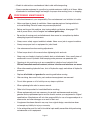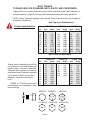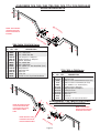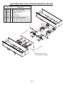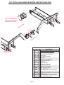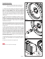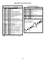
1
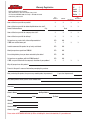
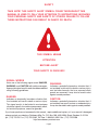
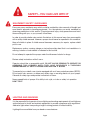
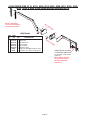
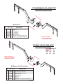
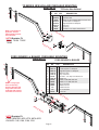
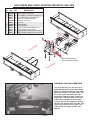
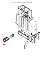
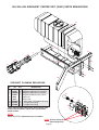
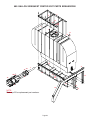
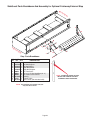
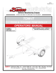
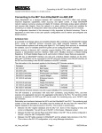
04/06 Rev.5
AC20037
U.S. Patent No. 6,286,870
Page 1
Thank you for purchasing Demco’s SIDEQUEST. We feel you have made a wise choice and hope
you are completely satisfied with your SIDEQUEST. If you have any questions regarding the applications
of certain solutions or chemicals, contact your chemical supplier and follow chemical manufacturer
recommendations as well as all licensing and use restrictions or regulations.
WARNING:
TO AVOID PERSONAL INJURY OR PROPERTY DAMAGE, OBSERVE
FOLLOWING INSTRUCTIONS:
Chemicals are dangerous. Know exactly what you're going to do and what is
going to happen before attempting to work with these products. Improper
selection or use can injure people, animals, plants and soil.
Always wear protective clothing such as coveralls, goggles and gloves when
working with chemicals or sprayer.
Be sure to dispose of all unused chemicals or solutions in a proper and
ecologically sound manner.
GENERAL INFORMATION
1. Unless otherwise specified, high-strength (grade5)
(3 radial-line head markings) hex head bolts are
used throughout assembly of this sprayer.
3. When placing a parts order, refer to this manual for
proper part numbers and place order by PART NO.
and DESCRIPTION.
2. Whenever terms "LEFT" and "RIGHT" are used in
this manual it means from a position behind sprayer
and facing forward.
Table of Contents
General information ............................................................................................................. 2
Warranty Registration ........................................................................................................ 3-4
Safty Information ............................................................................................................. 5-12
Safety Sign Locations ......................................................................................................... 7
Bolt Torque ......................................................................................................................... 13
Mounting Brackets Part Breakdowns .............................................................................. 14-20
Assembly Instructions ....................................................................................................... 21
Parts Breakdown ............................................................................................................ 21-22
Plumbing Breakdown ...................................................................................................... 23-26
Optional Jackstands Breakdown ........................................................................................ 27
Optional External Step Parts Breakdown and List .............................................................. 28
Optional Light Kit Parts Breakdown and List ...................................................................... 29
Sprayer Checklist .............................................................................................................. 31
Page 2
Warranty Registration
Dethmers Manufacturing Company
4010 320th Street • Box 189 • Boyden, Iowa 51234
Toll Free 800-54DEMCO (800-543-3626) • FAX 800-845-6420
www.demco-products.com
❍
❍
❍
❍
❍
Ag
RV
Rental
Brakes
Marine
Very
Satisfied
Satisfied
Dissatisfied
Very
Dissatisfied
How satisfied are you with our product?
❍
❍
❍
❍
How satisfied are you with the dealership/distributor sales staff?
Dealer/Distributor Name
City
❍
❍
❍
❍
How satisfied are you with the company sales staff?
❍
❍
❍
❍
How satisfied are you with the delivery?
❍
❍
❍
❍
Did you have any contact with a Demco Representative?
If YES, how satisfied were you?
YES
❍
NO
❍
❍
❍
I would recommend this product to my family and friends.
YES
NO
Would you purchase again from DEMCO?
YES
NO
Since taking delivery, have you been contacted by the dealer?
YES
NO
Did you have any problems with this DEMCO product?
If YES, are you satisfied with the company’s resolution of your problem?
YES
❍
NO
❍
❍
❍
State
Why did you purchase this product?
Please list the specific source of information prompting this purchase.
After purchasing this product, do you see any needed product improvement?
If yes, what improvement?
What other products would you like to see DEMCO offer?
Comments
Owner’s Name:
City:
Mailing Address:
State:
Zip Code:
Model#:
Serial #:
Purchase Date:
Owner’s Signature:
Please return to DETHMERS MFG. CO. By FAX or tri-folding this form to the backside, it is pre-addressed.
Page 3
Postage
Dethmers Manufacturing Company
4010 320th Street, Box 189
Boyden, Iowa 51234
Page 4
SAFETY
TAKE NOTE! THIS SAFETY ALERT SYMBOL FOUND THROUGHOUT THIS
MANUAL IS USED TO CALL YOUR ATTENTION TO INSTRUCTIONS INVOLVING
YOUR PERSONAL SAFETY AND SAFETY OF OTHERS. FAILURE TO FOLLOW
THESE INSTRUCTIONS CAN RESULT IN INJURY OR DEATH.
THIS SYMBOL MEANS
ATTENTION
BECOME ALERT
YOUR SAFETY IS INVOLVED!
SIGNAL WORDS
Note: use of the following signal words DANGER,
WARNING, and CAUTION with safety messages.
Appropriate signal word for each has been selected
using following guidelines:
DANGER:
Indicates an imminently hazardous situation that,
if not avoided, will result in death or serious injury.
This signal word is to be limited to most extreme
situations typically for machine components which,
for functional purposes, cannot be guarded.
WARNING:
Indicates a potentially hazardous situation that, if
not avoided, could result in death or serious injury,
and includes hazards that are exposed when
guards are removed. It may also be used to alert
against unsafe practices.
CAUTION:
Indicates a potentially hazardous situation that, if
not avoided, may result in minor or moderate injury.
It may also be used to alert against unsafe practices.
If you have questions not answered in this manual , require additional copies, or if your manual is damaged,
please contact your dealer or Dethmers Mfg. Co., P.O. Box 189, 4010 320th Street, Boyden, IA 51234
ph: (712) 725-2311 or (712) 725-2302 Toll Free: 1-800-543-3626 Fax: (712) 725-2380
http://www.demco-products.com
Page 5
SAFETY...YOU CAN LIVE WITH IT
EQUIPMENT SAFETY GUIDELINES
Every year many accidents occur which could be avoided by a few seconds of thought and
more careful approach to handling equipment. You, the operator, can avoid accidents by
observing precautions in this section. To avoid personal injury, study precautions and insist
those working with you, or you yourself, follow them.
In order to provide a better view, certain illustrations in this manual may show an assembly
with a safety shield removed. However, sprayer should never be operated in this condition.
Keep all shields in place. If shield removal becomes necessary for repairs, replace shield
prior to use.
Replace any caution, warning, danger or instruction safety decal that is not readable or is
missing. Location of such decals is indicated in this booklet.
Do not attempt to operate this sprayer under the influence of alcohol or drugs.
Review safety instructions with all users.
Operator should be a responsible adult. DO NOT ALLOW PERSONS TO OPERATE OR
ASSEMBLE THIS SPRAYER UNTIL THEY HAVE DEVELOPED A THOROUGH
UNDERSTANDING OF SAFETY PRECAUTIONS AND HOW IT WORKS.
To prevent injury or death, use a tractor equipped with a roll over protective system (ROPS).
Do not paint over, remove, or deface any safety signs or warning decals on your sprayer.
Observe all safety signs and practice instructions on them.
Never exceed limits of sprayer. If its ability to do a job, or to do so safely is in question
DON'T TRY IT.
LIGHTING AND MARKING
It is the responsibility of operator to know lighting and marking requirements of local highway
authorities and to install and maintain equipment to provide compliance with regulations.
Add extra lights when transporting at night or during periods of limited visibility.
Lighting kits are available from your dealer or manufacturer.
Page 6
SAFETY SIGN LOCATIONS
Part# 10328 Red
(on back side of tank)
WARNING
To prevent serious injury or death
• Refer to chemical supplier and manufacturer recommendations and all
licensing restrictions or regulations.
• Always wear recommended protective clothing when working with chemicals or
sprayer.
• Dispose of all unused chemicals or solutions in proper and ecologically
sound manner. Improper use can injure people, animals, plants and soil.
REV 1
AB21014
AB21014
WARNING
To prevent serious injury or
death.
Do not ride or stand on sprayer
while any part of sprayer is
moving.
Keep riders off at all times.
REV 1
AB21001
AB21001
WARNING
To prevent serious injury or death
• Store sprayer on hard level surface.
• Store empty.
REV 1
AB21002
Part# 10327 Amber
Page 7
AB21002
SAFETY SIGN CARE
• Keep safety signs clean and legible at all times.
• Replace safety signs that are missing or have become illegible.
• Replacement parts that displayed a safety sign should also display current sign.
• Safety signs are available from your distributor, dealer parts department, or manufacturer.
How to install safety signs:
• Be sure installation area is clean and dry.
• Decide on exact position before you remove backing paper.
• Remove smallest portion of split backing paper.
• Align decal over specified area and carefully press small portion with
exposed sticky backing in place.
• Slowly peel back remaining paper and carefully smooth remaining portion of
decal into place.
• Small air pockets can be pierced with a pin and smoothed out using piece of decal
backing paper.
TIRE SAFETY
• Failure to follow proper procedures when mounting tire on rim can produce an
explosion resulting in serious injury or death.
• Do not attempt to mount tire unless you have proper equipment and experience.
• Inflating or servicing tires can be dangerous. Whenever possible, trained personnel
should be called to service or mount tires.
• Always order and install tires and wheels with appropriate type and load capacity to
meet or exceed anticipated weight to be placed on sprayer.
REMEMBER
Your best assurance against accidents is a careful and responsible operator. If there is any
portion of this manual or function you do not understand, contact your local authorized dealer
or manufacturer.
BEFORE OPERATION:
• Carefully study and understand this manual.
• Do not wear loose-fitting clothing which may catch in moving parts.
• Always wear protective clothing and substantial shoes.
• It is recommended that suitable hearing and eye protection be worn.
• Operator may come in contact with certain materials which may require specific safety
equipment relative to handling of such materials. (Examples: extremely dusty, molds,
fungus, bulk fertilizers, etc.)
Page 8
• Keep wheel and lug nuts tightened to specified torque.
• Assure that agricultural implement tires are inflated evenly.
• Give sprayer a visual inspection for any loose bolts, worn parts, or cracked welds, and make
necessary repairs. Follow maintenance safety instructions included in this manual.
• Be sure there are no tools lying on or in equipment.
• Do not use the sprayer until you are sure that area is clear, especially around children and
animals.
• Don't hurry learning process or take sprayer for granted. Ease into it and become familiar
with your new equipment.
• Practice operation of your sprayer and its attachments. Completely familiarize yourself
and other operators with its operation before using.
• Use a tractor equipped with Roll Over Protection System (ROPS) and fasten your seat belt
prior to starting engine.
• Manufacturer does not recommend usage of tractor with ROPS removed.
• Move tractor wheels to widest recommended settings to increase stability.
• Do not allow anyone to stand between tongue or hitch and towing unit when backing
up to equipment.
DURING OPERATION
• Beware of bystanders, PARTICULARLY CHILDREN! Always look around to make sure it is
safe to start engine of towing unit or move sprayer. This is particularly important with higher noise
levels and quiet cabs, as you may not hear people shouting.
• NO PASSENGERS ALLOWED- Do not carry passengers anywhere on or in the tractor or
sprayer.
• Keep hands and clothing clear of moving parts.
• Do not clean, lubricate, or adjust your sprayer while it is moving.
• When halting operation, even periodically, set tractor or towing unit brakes, disengage
PTO, shut off engine, and remove ignition key.
• Be especially observant of operating area and terrain- watch for holes, rocks, or other hidden
hazards. Always inspect area prior to operation.
-
DO NOT operate near edge of drop-offs or banks.
-
DO NOT operate on steep slopes as overturn may result.
-
Operate up and down (not across) intermediate slopes. Avoid sudden starts and stops.
Page 9
• Pick the most level possible route when transporting across fields. Avoid edges of ditches,
gullies, and steep hillsides.
• Be extra careful when working on inclines.
• Periodically clear equipment of brush, twigs, or other materials to prevent buildup of dry
combustible materials.
• Maneuver tractor or towing unit at safe speeds.
• Avoid overhead wires or other obstacles. Contact with overhead lines could cause serious injury
or death.
• Avoid loose gravel, rocks, and holes; they can be dangerous for equipment operation or movement.
• Allow for sprayer length when making turns.
• Do not walk or work under raised components or attachments unless securely positioned and
blocked.
• Keep all bystanders, pets, and livestock clear of work area.
• Operate towing unit from operators seat only.
• Never stand alongside of unit with engine running or attempt to start engine and/or operate machine
while standing alongside of unit.
• Never leave running equipment attachments unattended.
• As a precaution, always recheck hardware on equipment following every 100 hours of operation.
Correct all problems. Follow maintenance safety procedures.
FOLLOWING OPERATION
• Following operation, or when unhitching, stop tractor or towing unit, set brakes, disengage
PTO and all power drives, shut off engine and remove ignition key.
• Store sprayer in an area away from human activity.
• Do not park sprayer where it will be exposed to livestock for long periods of time. Damage and
livestock injury could result.
• Do not permit children to play on or around the stored sprayer.
• Make sure all parked machines are on a hard, level surface and engage all safety devices.
• Wheel chocks may be needed to prevent unit from rolling.
Page 10
HIGHWAY AND TRANSPORT OPERATIONS
• SAFETY CHAINS: If equipment is going to be transported on a public highway, always
follow state and local regulations regarding safety chains and auxiliary lighting. Be sure to
check with local law enforcement agencies for your own particular regulations. If required
safety chains should be obtained and installed. Only safety chains (not elastic or nylon/plastic
tow straps) should be used to retain connection between towing and towed machines in event
of separation of primary attaching system. Use a high strength, appropriately sized hitch pin
with a mechanical retainer and attach safety chains. Criss cross chains under tongue and
secure to draw bar cage, mounting loops, or bumper frame.
• Adopt safe driving practices:
-
Keep brake pedals latched together at all times. NEVER USE INDEPENDENT BRAKING
WITH SPRAYER IN TOW. LOSS OF CONTROL OR UPSET MAY RESULT.
- Always drive at a safe speed relative to local conditions and ensure that your speed is low
enough for an emergency stop. Keep speed to a minimum.
- Reduce speed prior to turns to avoid risk of overturning.
- Always keep tractor or towing unit in gear to provide engine braking when going
downhill. Do not coast.
- Do not drink and drive!
• Comply with state and local laws governing highway safety and movement of farm machinery on
public roads.
• Use approved accessory lighting flags and necessary warning devices to protect operators of
other vehicles on highway during transport. Various safety lights and devices are available
from your dealer.
• Use of flashing amber lights is acceptable in most localities. However, some localities prohibit
their use. Local laws should be checked for all highway lighting and marking requirements.
• When driving tractor and sprayer under 20 mph (40 kph) day or night, use flashing amber warning
lights and a slow moving vehicle (SMV) identification emblem.
• Plan your route to avoid heavy traffic.
• Be a safe and courteous driver. Always yield to oncoming traffic in all situations, including narrow
bridges, intersections, etc.
• Be observant of bridge load ratings. Do not cross bridges rated lower than gross weight of unit
you are operating.
Page 11
• Watch for obstructions overhead and side to side while transporting.
• Always operate equipment in a position to provide maximum visibility at all times. Make
allowances for increased length and weight of sprayer when making turns, or stopping.
PERFORMING MAINTENANCE
•
Good maintenance is your responsibility. Poor maintenance is an invitation to trouble.
•
Make sure there is plenty of ventilation. Never operate engine of towing vehicle in
a closed building. Exhaust fumes may cause asphyxiation.
•
Before working on this machine, stop towing vehicle, set brakes, disengage PTO
and all power drives, shut off engine and remove ignition key.
•
Be certain all moving parts and attachments have come to a complete stop before
attempting to perform maintenance.
•
Always use a safety support and block wheels. Never use a jack to support machine.
•
Always use proper tools or equipment for job at hand.
•
Use extreme caution when making adjustments.
•
Follow torque chart in this manual when tightening bolts and nuts.
•
Never use your hands to locate a hydraulic leak on attachments. Use a small piece of
cardboard or wood. Hydraulic fluid escaping under pressure can penetrate skin.
•
Openings in skin and minor cuts are susceptible to infection from hydraulic fluid.
Without immediate medical treatment, serious infection and reactions can occur.
•
When disconnecting hydraulic lines, shut off hydraulic supply and relieve all hydraulic
pressure.
•
Replace all shields and guards after servicing and before moving.
•
After servicing, be sure all tools, parts and service equipment are removed.
•
Do not allow grease or oil to build up on any steps or platform.
•
When replacing bolts refer to owners manual.
•
Refer to bolt torque chart for head identification marking.
•
Where replacement parts are necessary for periodic maintenance and servicing,
genuine factory replacement parts must be used to restore your equipment to original
specifications. Manufacturer will not claim responsibility for use of unapproved parts or
accessories and other damages as a result of their use.
•
If equipment has been altered in any way from original design, manufacturer does
not accept any liability for injury or warranty.
•
A fire extinguisher and first aid kit should be kept readily accessible while performing
maintenance on this equipment
Page 12
BOLT TORQUE
TORQUE DATA FOR STANDARD NUTS, BOLTS, AND CAPSCREWS.
Tighten all bolts to torques specified in chart unless otherwise noted. Check tightness of
bolts periodically, using bolt chart as guide. Replace hardware with same grade bolt.
NOTE: Unless otherwise specified, high-strength Grade 5 hex bolts are used throughout
assembly of equipment.
Bolt Torque for Standard bolts *
Torque Specifications
“A”
1/4”
5/16”
3/8”
7/16”
1/2”
9/16”
5/8”
3/4”
7/8”
1”
GRADE 2
lb-ft (N.m)
GRADE 5
lb-ft (N.m)
GRADE 8
lb-ft (N.m)
6
10
20
30
45
70
95
165
170
225
9
18
30
50
75
115
150
290
420
630
12
25
45
80
115
165
225
400
650
970
(8)
(13)
(27)
(40)
(60)
(95)
(130)
(225)
(230)
(300)
(12)
(25)
(40)
(70)
(100)
(155)
(200)
(390)
(570)
(850)
(16)
(35)
(60)
(110)
(155)
(220)
(300)
(540)
(880)
(1310)
Bolt Torque for Metric bolts *
“A”
Torque figures indicated are valid for
non-greased or non-oiled threads and
heads unless otherwise specified.
Therefore, do not grease or oil bolts or
capscrews unless otherwise specified
in this manual. When using locking
elements, increase torque values
by 5%.
* GRADE or CLASS value for bolts
and capscrews are identified by their
head markings.
6
7
8
10
12
14
16
18
20
22
24
CLASS 8.8
lb-ft
(N.m)
CLASS 9.8
lb-ft
(N.m)
CLASS 10.9
lb-ft
(N.m)
9
15
23
45
78
125
194
268
378
516
654
10
18
25
50
88
140
216
-----
13
21
31
61
106
170
263
364
515
702
890
GRADE-2
CLASS 8.8
8.8
Page 13
(13)
(21)
(31)
(61)
(106)
(169)
(263)
(363)
(513)
(699)
(886)
GRADE-5
CLASS 9.8
9.8
(14)
(24)
(34)
(68)
(118)
(189)
(293)
-----
GRADE-8
CLASS 10.9
10.9
(17)
(29)
(42)
(83)
(144)
(230)
(357)
(493)
(689)
(952)
(1206)
JOHN DEERE 7510, 7520, 7600, 7700, 7800, 7610, 7710, 7810 OVER-HEAD
MOUNTING BRACKETS
14
14
10
10
11
Re
NOTE: Front fenders
need to be removed
before installation of
brackets.
7 8
ar
5
13
tor
3
9
6
2
11
7600-7800 & 7610-7810 Series
REF. PART
DESCRIPTION
NO. NO. QTY.
1. 00482
8 1/2”-13UNC x 1 3/4” Hex Hd Bolt (Gr.5)
2. 00084
8 1/2” Lockwasher
3. 00083
8 1/2”-13UNC Hex Nut
4. 11660-35 1 Left Baseplate for Sidequest
5. 11661-35 1 Right Baseplate for Sidequest
6. 10166-35 1 Spacer Assembly
7. 00254 10 3/4”-10UNC Nut
8. 00253 10 3/4” Lockwasher
9. 01235 10 3/4”-10UNC x 2” Hex Head Bolt (Gr.5)
10. 11442-35 4 Drop Channel
11. 11644-35 2 Extension Arm
12. 11651-95 2 Upper Pin
13. 02397
4 Lynch Pin
14. 06102
4 1/2”NC X 1.25” Cup Point Set Screw
4
2 3
10
10
7720, 7820, & 7920 Series
REF. PART
NO. NO. QTY.
1.
2.
3.
4.
5.
6.
7.
8.
9.
10.
11.
12.
1
12
1
2
3
7
8
7
Fro
1
nt
of
Tra
13
cto
r
12
NOTE: Bracket #8 and #9
must be installed to the
tractor frame first using
three 20mm x 50mm
bolts.
Tra
c
9
12
12
of
DESCRIPTION
11442-35 4 Drop Channels
11644-35 2 Extension Arm
03840
12 20mm x 2.5mm X 50mm Metric Bolt (Gr. 10.9)
11745
4 20mm X 2.5mm x 75mm Metric (Gr. 10.9)
04052
6 3/4”-10UNC x 1-1/2” Hex Bolt (Gr.5)
11739-35 1 Left Baseplate for Sidequest
11740-35 1 Right baseplate for Sidequest
11741-35 1 Left Spacer Plate
11742-35 1 Right Spacer Plate
11651-95 2 Upper Pin
02397
4 Lynch Pin
06102
4 1/2” NC x 1.25” Cup Point Set Screw
JOHN DEERE 7720, 7820, & 7920 OVERHEAD MOUNTING BRACKETS
ar
Re
11
of
Tra
c
NOTE: Front fenders
must be removed before
installation of brackets.
tor
10
3
11
NOTE: Bolt #5 is only
installed in these three
holes on both brackets.
6
8
9
3
2
3
10
Fro
nt
of
Tra
cto
r
Page 14
7
5
5
4
1
1
JOHN DEERE 8100, 8110, 8120, 8200, 8210, 8220, 8300, 8310, 8320, 8400,
8410, 8420, & 8520 OVER-HEAD MOUNTING BRACKETS
8
3
8
3
6
NOTE: Front fenders
must be removed before
installation of brackets.
Re
ar
7
7
1
8000 Series
of
5
Tra
c
tor
7
4
2
REF. PART
NO.
NO. QTY.
DESCRIPTION
1.
02397
4 Lynch Pins
2. 11651-95 2 Upper Pins
3. 11442-35 4 Drop Channels
4. 11645-35 1 Lt. Baseplate
5. 11646-35 1 Rt. Baseplate
6. 11644-35 2 Extension Arms
7.
03840
8 20mm X 2.5mm Metric Bolt (Gr. 10.9)
8.
06102
4 1/2”NC x 1-1/4” Cup Point Set Screw
7
1
6
2
Fro
nt
of
Tra
cto
r
3
3
Adapter Spacer Kit (5839)
is needed for 8420 & 8520
& 30 series with power
shift only.
Please order replacement parts by PART NO. and DESCRIPTION
NOTE: Adapter may also
be required for tractors
with independent link
suspension.
8
JOHN DEERE 8420, 8520, & 30’s w/ Power Shift
OVER-HEAD MOUNTING BRACKETS
8
3
3
6
Re
ar
7
of
5
Tra
c
tor
7
1
4
2
7
7
1
JOHN DEERE 8420, 8520, & 30’s w/ Power Shift
REF. PART
NO.
NO. QTY.
DESCRIPTION
1.
02397
4 Lynch Pins
2. 11651-95 2 Upper Pins
3. 11442-35 4 Drop Channels
4. 12318-35 1 Lt. Baseplate
5. 12319-35 1 Rt. Baseplate
6. 11644-35 2 Extension Arms
7.
03840
8 20mm X 2.5mm Metric Bolt (Gr. 10.9)
8.
06102
4 1/2”NC x 1-1/4” Cup Point Set Screw
Fro
2
nt
of
Tra
cto
r
7
7
7
6
8
3
8
3
NOTE: Front fenders
must be removed before
installation of brackets.
Please order replacement parts by PART NO. and DESCRIPTION
Page 15
8
JOHN DEERE 30’S IVT OVER-HEAD
MOUNTING BRACKETS
8
3
6
3
Re
ar
of
Tra
cto
5
r
7
7
1
4
7
7
2
1
30 Series IVT
REF. PART
NO.
NO.
1.
02397
2. 11651-95
3. 11442-35
4. 12333-35
5. 12332-35
6. 11644-35
7.
03840
8.
06102
QTY.
DESCRIPTION
4 Lynch Pins
2 Upper Pins
4 Drop Channels
1 Lt. Baseplate
1 Rt. Baseplate
2 Extension Arms
8 20mm X 2.5mm Metric Bolt (Gr. 10.9)
4 1/2”NC x 1-1/4” Cup Point Set Screw
7
7
Fro
2
nt
of
Tra
cto
r
6
7
8
8
3
3
NOTE: Front fenders
must be removed before
installation of brackets.
Please order replacement parts by PART NO. and DESCRIPTION
8
MX MAG. 180-270 OVER-HEAD
MOUNTING BRACKETS
8
4
4
NOTE:Brackets Fit
180 200 210
230 220 240
255 270 285
5
1
NOTE: Front fenders
must be removed before
installation of brackets.
1
1
7
Re
ar
of
Tra
cto
r
3
6
MX Magnum Parts
7
Fro
nt
of
6
Tra
cto
r
Breakdown
REF. PART
DESCRIPTION
NO. NO. QTY.
1. 03840
6 20mm x 2.5 x 50mm Hex Bolt (Gr. 10.9)
2. 11440-35 1 Left Mounting Baseplate
3. 11441-35 1 Right Mounting Baseplate
4. 11442-35 4 Drop Channel
5. 11644-35 2 Extension Arm
6. 11651-95 2 Upper Pin
7. 02397
4 Lynch Pin
8. 06102
4 1/2”NC X 1.25” Cup Point Set Screw
Page 16
2
1
1
5
4
4
TG SERIES NEW HOLLAND OVER-HEAD MOUNTING
BRACKETS
TG Series New Holland
REF. PART
NO. NO. QTY.
8
8
1
1.
2.
3.
4.
5.
6.
7.
8.
1
NOTE: Front fenders, if
applicable, must be
removed before installation of brackets.
2
11442-35
11644-35
03840
11647-35
11648-35
11651-95
02397
06102
Re
3
3
ar
of
5
3
6
Drop Channels
Extension Arm
20mm x 2.5mm X 50mm Metric Bolt (Gr. 10.9)
Left Baseplate for Sidequest
Right baseplate for Sidequest
Upper Pin
Lynch Pin
1/2” NC x 1.25” Cup Point Set Screw
Tra
c
7
NOTE:Brackets Fit
TG210 TG230 TG255
TG285
DESCRIPTION
4
2
8
1
1
2
4
4
3
tor
4
Fro
nt
of
Tra
cto
r
7
3
6
2
FORD GENESIS & BUHLER OVER-HEAD MOUNTING
BRACKETS
1
FORD GENESIS & BUHLER
REF. PART
NO. NO. QTY.
5
6
1.
2.
3.
4.
5.
6.
7.
8.
9.
10.
11.
12.
13.
14.
5
6
NOTE: If using upper
holes on mounting
brackets. Brackets will
hang below tank frame.
It will NOT void warranty
if brackets are cut flush.
4
8
10052-35
12059-35
12060-35
11644-35
11442-35
06102
11651-95
02389
00482
00084
00083
00
00
02397
1
1
1
2
4
4
2
8
8
8
8
8
8
4
8
13
14
9
9
7
Fro
nt
of
Tra
cto
r
12
10 11
DESCRIPTION
Spacer Assembly
Left Baseplate for Sidequest
Right Baseplate for Sidequest
Extension Arm
Drop Channels
1/2” NC x 1.25” Cup Point Set Screw
Upper Pin
.75NC X 5.00 GR5 Hex Bolt
.50NC X 1.75 GR5 Hex Bolt
.50 Lockwasher
.50NC Hex Nut
.75NC Hex Nut
.75 Lockwasher
Lynch Pin
Re
12
1
ar
of
Tra
c
13
tor
3
8
1
8
14
7
NOTE:Brackets Fit
FORD GENESIS: 8670, 8770, 8870, 8970
BUHLER: 2145, 2160, 2180, 2210
4
2
9
9
5
Page 17
5
JOHN DEERE 8000 TRACK MOUNTING BRACKETS AND SKID
REF. PART
DESCRIPTION
NO. NO. QTY.
1. 12315-35 1 Right Baseplate for Sidequest
2. 12316-35 1 Left Baseplate for Sidequest
3. 02851
8 3/4”-10UNC x 8.50 Hex Head Bolt (Gr. 5)
4. 02961
8 3/4”-10UNC Nylon Insert Lock Nut
5. 12317 12 20mm-2.5 x 250mm Hex Bolt
6. 12186-95 4 Top Pin 1.25 x 10.25
7. 02397
8 Lynch Pin
8. 12185-35 4 Extension Arm
9. 00085 24 1/2” Flat Washer
10. 01254 24 1/2”NC x 1.50 Hex Head Bolt (Gr. 5)
11. 02178 24 1/2”NC Nylon Insert Lock Nut
12. 35631
2 350gal. Skid Assembly (tank not shown)
35632
2 500gal. Skid Assembly (tank not shown)
12
11
11
9
10
9
7
7
5
10
5
6
9
4
tor
ac
r
T
of
ar
e
R
10
9
10
8
4
4
2
7
4
8
7
6
3
1
3
3
Use existing 6 washers
From removed track bolts
3
tor
c
a
f Tr
to
n
Fro
12
Installation John Deere 8000 Track
Use any three holes in a row of the five
holes depending on the track width. When
position is determined remove every other
bolt of the six bolts in the track mount, that
will match up with the three bolts (#5) in
the bracket. Repeat for other side of track
mounting. On the row of bolts to the front
of the tractor, hold bolts in bracket up to
just short of flush of the bottom of bracket,
secure in that position with vice grips. Also
adjust track so bolts will miss lugs. Then
slide in place and tighten all bolts. See
diagram.
Page 18
JOHN DEERE 9000 TRACK MOUNTING BRACKETS AND SKID
REF. PART
DESCRIPTION
NO. NO. QTY.
1. 12183-35 2 Right Baseplate for Sidequest
2. 12184-35 2 Left Baseplate for Sidequest
3. 03840 32 20mm-2.5 x 50mm Hex Bolt
6. 12186-95 4 Top Pin 1.25 x 10.25
7. 02397
8 Lynch Pin
8. 12185-35 4 Extension Arm
9. 00085 24 1/2” Flat Washer
10. 01254 24 1/2”NC x 1.50 Hex Head Bolt (Gr. 5)
11. 02178 24 1/2”NC Nylon Insert Lock Nut
12. 35631
2 350gal. Skid Assembly (tank not shown)
35632
2 500gal. Skid Assembly (tank not shown)
12
11
11
9
10
9
7
10
7
10
6
tor
ac
r
T
of
ar
Re
2
9
3
8
3
3
7
8
3
7
6
1
3
2
3
10
1
3
r
cto
a
r
fT
to
n
o
Fr
3
Simulation of track mount
( not a component of bracket)
12
Page 19
9
CAT MT765 CHALLENGER MOUNTING BRACKETS AND SKID
6
1
7
5
6
17
12
*Note: For installing Hub
Spacer remove every other
bolt from hub on tractor.
15
18
10
r
cto
a
r
T
of
ar
e
R
15
16
16
15
16
19
20
19
16
15
13
18
2
3
4
9
4
8
9
10
17
tor
ac
r
T
of
nt
o
r
F
8
18
13
15
14
18
15
15
11 15 16 14
15
16
16
16
16
REF. PART
DESCRIPTION
NO. NO. QTY.
1. 5619-35 2 Spindle Assembly (details on p.21 view B
& view C & Breakdown on p.22
2. 12334-30 1 Right Baseplate for Sidequest
3. 12335-30 1 Left Baseplate for Sidequest
4. 12379-30 2 Back Plate
5. 12378-35 2 Hub Spacer Assembly
6. 12331-95 18 Bushings
7. 12385 18 24mm-3 x 50mm Hex Bolt
8. 11651-95 2 Top Pin 1.25 x 10.25
9. 02397
4 Lynch Pin
10. 11644-35 2 Extension Arm
11. 12382-35 1 Spacer Channel, Right
12. 12383-35 1 Spacer Channel, Left
13. 12384-35 2 Spacer Channel, Center
14. 00083 18 1/2”-UNC Hex Hd. Nut
15. 00084 18 1/2” Lockwasher
16. 00482 18 1/2”-UNC x 1 3/4” Gr.5 Hex Hd. Bolt
17. 35631W 2 350gal Skid Assembly w (tank not shown)
- 35632W 2 500gal Skid Assembly w (tank not shown)
18. 11442-35 4 Drop Channels
19. 09114 10 7/8”-UNC x 3.50” GR.5 Hex Hd. Bolt
20. 10678 10 7/8”-UNC Nylon Lock nut
Please order replacement parts by PART NO. and DESCRIPTION
Page 20
Assembly Instructions
Preparation: Remove any loader brackets from the tractor. The
tractors duals must be set to 120” wheel spacing.
1. Remove every other lug bolt on the tractor’s dual, and replace
them with the special spacer Stud Bolts included with the SideQuest
hardware as shown in VIEW A. (Note: Only when replacing stud
bolts on a JD 7000 Series Tractor, the existing washers MUST be
used). After all of the removed lug bolts are replaced, remove the
rest of the tractor’s lug bolts and replace them with the SideQuest
stud bolts. Torque the SideQuest stud bolts to tractor manufacturer’s
specifications.
2. Bolt the Hub Spacer to the SideQuest stud bolts as shown in
VIEW B. Use ten 7/8”-UNF x 2” hex head bolts and ten 7/8” lockwashers.
Then bolt the Hub/Spindle Assembly to the Hub Spacer. Use eight 5/
8”-UNF x 2” hex head bolts and lockwashers to bolt the Hub/Spindle
Assembly to the Hub Spacer. Torque all bolts to the specifications
found earlier in the manual.
13
VIEW A
3. Mount the Left and Right Base Plates to the tractor’s frame. All Base
Plates will mount between the tractors cab and front wheels to existing
holes in the tractors frame. All tractors’ mounting brackets can be viewed
on pages 14-16.
4. Mount the Tank Holder with Tank, and Tank Hold Downs. Before
mounting, decide which height setting is desirable. There are two height
settings. Slide the Tank holder over the spindle as shown in VIEW C.
Make sure the arrow on the end of the spindle is always pointing up as
shown. Use the bottom hole for a higher height setting, and use the
top hole for a lower height setting. Slide the tank holder in until there is
a spacing of approximately 2” between the tire and the Tank Holder.
Use four 1/2”-UNC x 1 1/4” set screws to hold the spindle in place.
Turn the set screws into the threaded inserts on the outside of the tube
the spindle has been placed in.
5. Next bolt the Mounting Extension Arm to the Tank Holder. Use four 1/
2”-UNC x 1 3/4” hex head bolts, four 1/2” lockwashers, and four 1/2”
hex nuts.
4
24
22
1
17
19
VIEW B
6. Repeat same instructions for the opposite side.
NOTE:
View A, B, & C use parts list on next page.
1
23
VIEW C
Page 21
23
SIDEQUEST PARTS BREAKDOWN
5502 Hub Breakdown
REF.
NO.
PART
NO.
QTY.
DESCRIPTION
1.
2.
3.
4.
5.
6.
7.
8.
9.
10.
11.
12.
13.
--.
--.
--.
5619-35
5502-35
10155-35
10066-35
10214-35
10215-35
10924-35
10923-35
10918-35
11644-35
11442-35
10219-35
10064-90
10248-90
10247-90
10261-90
2
2
2
2
16
2
12
3
2
1
2
2
20
20
20
20
14.
15.
16.
17.
18.
19.
20.
21.
22.
23.
24.
25.
26.
10245
00083
00084
00248
00482
00965
01254
02592
10284
06102
10360
01253
00085
8
8
14
16
8
16
14
16
20
12
20
6
20
Hub & Spindle Assembly
Hub Assembly (#608 non-braking)
Spindle
Hub Spacer
Tank Hold Down (350 gal. ONLY)
Tank Hold Down (500 gal. ONLY)
Tank Support Tube (500 gal. ONLY)
Support Crossbar (500 gal. ONLY)
Top Angle Support (500 gal. ONLY)
Mounting Extension Arm
Hanger Bracket
Tank carrier
Stud Spacer Bolts John Deere
Stud Spacer Bolts Ford Genesis
Stud Spacer Bolts Case IH 71, 72, & 89
Stud Spacer Bolts Case IH MX Magnum
and T G New Holland
Cable Assembly
1/2”-UNC Hex Hd. Nut
1/2” Lockwasher
5/8” Lockwasher
1/2”-UNC x 1 3/4” Gr.5 Hex Hd. Bolt
5/8”-UNF x 2” Gr.5 Hex Hd. Bolt
1/2”-UNC x 1 1/2” Gr.5 Hex Hd. Bolt
3/8”-UNC Nylon Insert Locknut
7/8”-UNF x 2” Gr.5 Hex Hd. Bolt
Set Screw 1/2” x 1.25 Cup Point
7/8” Lockwasher
1/2”-UNC x 2” Gr. 5 Hex Head Bolt
1/2” Flatwasher
REF.
NO.
PART
NO.
QTY.
--.
A.
B.
C.
D.
E.
F.
G.
*H.
*I.
*J.
5502
01944
01942
01943
09304
01938
01937
01933
01936
01934
00191
2
1
1
1
1
1
1
1
1
1
1
DESCRIPTION
Hub Assembly (#608 non-braking)
Oil Seal
Inner Cone Bearing
Inner Cup
Hub
Outer Cup
Outer Cone Bearing
Dust Cap
2 1/4” x 1 1/32” Hardened Washer
Castle Nut
3/16” x 1 1/2” Cotter Pin
*Items H,I, and J are
shown for reference only
and are not included in
hub assembly 5502
NOTE:
Refer to this parts list for parts shown on pages 17-20.
Page 22
E
F
H
G
I
J
A
B
D
C
350 GALLON SIDEQUEST PARTS BREAKDOWN
1
21
14
1
51
23
10
17
4
19
5
12
11
32
1
12
22
8
24
7
26
1
23
13
9
23
10
116
120
15
46
16
10
11
18
SIDEQUEST PLUMBING BREAKDOWN
REF.
NO.
PART
NO.
QTY.
DESCRIPTION
--. P350WA 2 350 gallon SideQuest Tank (white)
--. P350A
2 350 gallon SideQuest Tank (yellow)
--. P500WA 2 500 gallon SideQuest Tank (white)
--. P500A
2 500 gallon SideQuest Tank (yellow)
P1. 09941
1 Agitator Jet
P2. 10267
1 Siphon Tube
P3. BRB1034 1 1” MPT to 3/4” FPT Reducer Bushing
P4. FTF100
1 1” Flanged Tank Fitting
P5. FTF200
1 2” Flanged Tank Fitting
P6. LL100
1 1” FPT Elbow
P7. PP180
-- 1” Polypropylene Pipe
* When ordering replacement tanks, please specify if the
tank you need is either a right or left or center and/or
yellow or white.
NOTE: All units will attach straight
fittings here except for the overhead units. Those brackets will use
elbows here.
Page 23
1
P1
P3
1
1
P6
P7
1
P4
1
1
P2
1P5
500 GALLON SIDEQUEST PARTS BREAKDOWN
9
8
25
16
16
7
20
26
7
7
12
14
21
12
6
12
23
9
17
3
6
24
4
19
11
11
31
12
12
7
22
16
12
12
20
22
13
8
23
9
12
26
15
45
10
10
NOTE:
Refer to p.22 for replacement part numbers.
Page 24
16
18
350 GALLON SIDEQUEST CENTER EXIT (35631) PARTS BREAKDOWN
21
14
5
23
9
11
17
19
3
12
22
24
26
2
13
23
16
20
15
4
16
18
10
SIDEQUEST PLUMBING BREAKDOWN
REF.
NO.
PART
NO.
QTY.
--.
--.
--.
--.
P1.
P2.
P3.
P4.
P5.
P350WA
P350A
P500WA
P500A
09941
10267
BRB1034
FTF100
FTF200
2
2
2
2
1
1
1
1
1
DESCRIPTION
350 gallon SideQuest Tank (white)
350 gallon SideQuest Tank (yellow)
500 gallon SideQuest Tank (white)
500 gallon SideQuest Tank (yellow)
Agitator Jet
Siphon Tube
1” MPT to 3/4” FPT Reducer Bushing
1” Flanged Tank Fitting
2” Flanged Tank Fitting
* When ordering replacement tanks, please specify if the
tank you need is either a right or left or center and/or
yellow or white.
NOTE:
Refer to p.22 for replacement part numbers.
P1
P3
P4
P2
P5
NOTE: All units will attach
elbow fittings here.
Page 25
500 GALLON SIDEQUEST CENTER EXIT PARTS BREAKDOWN
9
8
25
16
16
7
20
26
7
7
14
15
21
15
6
15
23
9
17
3
6
24
4
19
11
11
31
15
12
7
22
923
16
15
15
20
22
13
8
15
26
15
45
16
10
10
NOTE:
Refer to p.22 for replacement part numbers.
Page 26
18
OPTIONAL SIDEQUEST JACKSTANDS BREAKDOWN
Notes:
Adjustable jack may be used in two locations.
On the outside of the Stand Mount Bracket
as well as in the rear of the Tank holder.
REF.
NO.
PART
NO.
QTY.
1.
2.
3.
4.
5.
6.
7.
8.
9.
10.
11.
12.
13.
14.
07551-35
10199-35
10243
10244-35
00182
00477
00489
01718-95
02496
02587
04445
00060
00061
00907
4
2
2
2
2
8
4
4
4
4
4
6
6
6
DESCRIPTION
Wheel Stand
Stand Mounting Bracket
Caster Wheel Assembly
Adjustable Jack Assembly
Hair Pin, 7 gauge
5/8” Flatwasher
5/8”-UNC Jam Nut
Lock pin
5/8”-UNC x 4” Hex Hd Bolt Gr.5
5/8”-UNC Nylon Insert Locknut
6” x 2” Black Wheel with bushing
3/8” Lockwasher
3/8”-UNC Hex Hd. Nut
3/8”-UNC x 1” Hex Hd. Bolt Gr.5
12
1
8
2
13
14
5
10
6 11
6
7
9
4
3
Page 27
SideQuest Parts Breakdown And Assembly for Optional Fold-away External Step
Re
ar
of
Tra
c
tor
4
5
8
7
Fro
nt
of
Tra
cto
r
7
6
11
7
3
9
6
8
1
7
2
8
Step Parts Breakdown
7
REF. PART
DESCRIPTION
NO. NO. QTY.
1. 11446-35 2 External Step
2. 11447-35 2 Left Step Support
3. 11448-35 2 Left Step Mount
4. 11449-35 2 Right Step Mount
5. 11450-35 2 Right Step Support
6. 00059 20 3/8” Flatwasher
7. 00523 16 3/8” x 1-1/4” Hex Head Bolt (Gr. 5)
8. 02592 16 3/8” Nylon Insert Locknut
9. 07919-95 8 Bushing
10. 11451
4 Support Cable
11. 10219-35 1 Tank Carrier (Not Included w/Kit)
Please order replacement parts by PART NO. and DESCRIPTION.
NOTE: Part quantities are for both sides, but
only one side is shown.
Page 28
8
8
10
7
6
6
9
3
NOTE: TO ADJUST ANGLE OF STEP
ADJUST THE CABLES TOP BOLT
TO ONE OF 3 HOLE POSITIONS.
10
OPTIONAL SIDEQUEST LIGHT KIT PARTS BREAKDOWN
PARTS LIST
REF. PART
NO.
NO. QTY.
DESCRIPTION
1.
00214
8 .25” Flat Washer
2.
02772
8 .25” UNC Nylon Insert Lock Nut
3.
04055
8 .25” x 1.00” UNC Bolt, Grade 5
4.
07416
1 Male Connector Plug
5.
09058
1 Wire Harness (90’ X-Fold Clearance Lights)
--.
10032
1 Left Dual Ag Light
7.
10033
1 Right Dual Ag Light
8. 10329-35 1 Light Mounting Bracket
Please order replacement parts by PART NO. and DESCRIPTION
7
2
2
4
5
2
8
1
1
1
3
1
3
3
Page 29
3
NOTES:
Page 30
SPRAYER CHECKLIST:
Downtime caused by field breakdowns is costly and time consuming. Many breakdowns can be
eliminated by periodic equipment maintenance. By spending time reviewing this checklist before
seasonal spraying application time and following proper after season care, you can save time and
money later.
!
WARNING: To Prevent Serious Injury Or Death
•
Keep hands, feet, and loose clothing away from rotating parts.
•
Wear protective clothing recommended by your chemical and
fertilizer manufacturer when working with chemicals.
Check Before Going To The Field :
After Season Care:
1.
NOTE: It is important to wear proper safety equipment
when cleaning the SIDEQUEST . See your
chemical or fertilizer package for this information.
NOZZLES
Check tip for excessive wear by checking for grooves in
or near tip opening. Check nozzle spacing by starting at
center and working outwards. Check boom for proper
height.
1.
After spraying chemicals, run water mixed with cleaners
through tank, pump and all hose hookups. If wettable
powder dries out in the system, it is very difficult to put
back into suspension and can cause malfunction,
damage or injury.
2.
When cleaned, tank should have all openings closed or
covered to keep dirt from entering.
3.
Pump should be flushed with soluble oil and pump ports
plugged to keep out moisture and air.
4.
Disassemble tips and rinse with water or cleaning
solution. (Appropriate for chemical sprayed).
5.
PUMP
Check to be sure pump turns freely.
Clean tip opening with a wooden toothpick. Never use
wire or hard object that could distort opening.
6.
FRAME
Be sure all bolts are tightened.
Dispose of all unused chemicals or solutions in a proper
and ecologically sound manner.
6.
Water rinse and dry tips before storing.
2.
HOSES
Check all hoses for worn or soft spots. Be sure all hose
clamps are tightened and hoses are not kinked or pinched.
Check for leakage in any lines.
3.
TANK
Remove and clean agitator orifices. Check orifices for
excessive wear by checking for grooves in or near orifice
opening. Inspect fitting and grommets to insure they are
in good condition.
4.
5.
6.
7.
CONTROLS
Check for leakage, plugging, or wear on all valves,
fittings, etc. Clean off any build up of foreign material.
REPLACEMENT PARTS
Replace all worn or damaged parts.
NOTE: DETHMERS MANUFACTURING COMPANY
does not and will not make any recommendations
concerning application of various chemicals or
solutions. These recommendations relate to either
amount or procedure of materials applied. If you
have any questions regarding application of certain
chemicals or solutions, contact your chemical
supplier and follow chemical manufacturer
recommendations.
Page 31
DETHMERS MFG. COMPANY
P.O. BOX 189
4010 320th St., BOYDEN, IA. 51234
PH: (712) 725-2311 FAX: (712) 725-2380
TOLL FREE: 1-800-54DEMCO (1-800-543-3626)
www.demco-products.com
Page 32