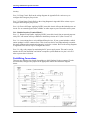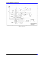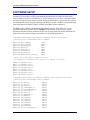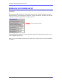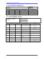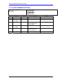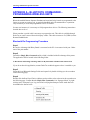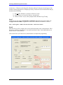
1
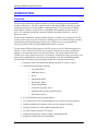
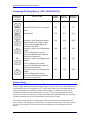
^ USER MANUAL
1
^2 Advantage 900
Remote Operator Pendant
^3 Handheld Machine Control Device
^4 3AO-ROPEND-363
^5 April 10, 2008
Single Source Machine Control
Power // Flexibility // Ease of Use
21314 Lassen Street Chatsworth, CA 91311 // Tel. (818) 998-2095 Fax. (818) 998-7807 // www.deltatau.com
Copyright Information
© 2008 Delta Tau Data Systems, Inc. All rights reserved.
This document is furnished for the customers of Delta Tau Data Systems, Inc. Other uses
are unauthorized without written permission of Delta Tau Data Systems, Inc.
Information contained in this manual may be updated from time-to-time due to product
improvements, etc., and may not conform in every respect to former issues.
To report errors or inconsistencies, call or email:
Delta Tau Data Systems, Inc. Technical Support
Phone: (818) 717-5656
Fax: (818) 998-7807
Email: [email protected]
Website: http://www.deltatau.com
Operating Conditions
All Delta Tau Data Systems, Inc. motion controller products, accessories, and amplifiers
contain static sensitive components that can be damaged by incorrect handling. When
installing or handling Delta Tau Data Systems, Inc. products, avoid contact with highly
insulated materials. Only qualified personnel should be allowed to handle this
equipment.
In the case of industrial applications, we expect our products to be protected from hazardous or
conductive materials and/or environments that could cause harm to the controller by damaging
components or causing electrical shorts. When our products are used in an industrial
environment, install them into an industrial electrical cabinet or industrial PC to protect them
from excessive or corrosive moisture, abnormal ambient temperatures, and conductive materials.
If Delta Tau Data Systems, Inc. products are exposed to hazardous or conductive materials and/or
environments, we cannot guarantee their operation.
REVISION HISTORY
REV.
DESCRIPTION
DATE
CHG
APPVD
1
PRELIMINARY MANUAL CREATION
01/28/08
Cp
V. BUROKAS
1
UPGRADE TO FULL RELEASE STATUS
04/09/08
CP
V. BUROKAS
Advantage 900 Remote Operator Pendant
Table of Contents
INTRODUCTION .......................................................................................................................................................3
Overview.......................................................................................................................................................................3
Part Numbering ...........................................................................................................................................................4
Compatibility ...............................................................................................................................................................4
Communication Interface ...........................................................................................................................................5
Specifications................................................................................................................................................................5
HARDWARE SETUP .................................................................................................................................................7
Jumper Configuration.................................................................................................................................................7
Advantage 900 Remote Pendant – (P/N: 300-603812-10x) ......................................................................................7
Advantage 900 Relay Board – (P/N: 300-603826-10x) ............................................................................................8
Connections ..................................................................................................................................................................8
Advantage 900 Remote Operator Pendant ................................................................................................................8
Advantage 900 Relay Board......................................................................................................................................9
Field-Wiring Connections .......................................................................................................................................10
Wired diagram.........................................................................................................................................................11
SOFTWARE SETUP ................................................................................................................................................13
WIRELESS SOFTWARE SETUP...........................................................................................................................15
MOUNTING AND INSTALLATION .....................................................................................................................17
Mechanical Drawing..................................................................................................................................................18
Advantage 900 Relay Board Mechanical Layout....................................................................................................20
Advantage 900 Pendant Board Mechanical Layout ...............................................................................................21
CONNECTOR DESCRIPTIONS – 900 REMOTE PENDANT............................................................................23
J1: KEYPAD INPUT CONNECTION ....................................................................................................................23
J1 KEYPAD INPUT CONNECTION (10-PIN SOCKET) .................................................................................23
J2: USB CONNECTION............................................................................................................................................23
J3: HANDWHEEL CONNECTION..........................................................................................................................24
J4: KEYPAD LED CONNECTION...........................................................................................................................24
J5: ON/OFF SWITCH CONNECTION ...................................................................................................................25
J6: ESTOP INDICATION CONNECTION .............................................................................................................25
J7: BATTERY CHARGE CONNECTION ................................................................................................................25
J8: RS-232 CONNECTION .......................................................................................................................................26
Table of Contents
i
Advantage 900 Remote Operator Pendant
J9: BATTERY CONNECTION..................................................................................................................................26
CONNECTOR DESCRIPTIONS – 900 RELAY BOARD ....................................................................................27
J4: PC POWER CONNECTION ...............................................................................................................................27
J7: RS-232 CONNECTION .......................................................................................................................................27
J8: POWER ON PUSHBUTTON CONNECTION...................................................................................................27
J9: E-STOP SWITCH CONNECTION .....................................................................................................................28
J13: (10-PIN TERMINAL BLOCK)........................................................................................................................28
J14: (6-PIN TERMINAL BLOCK) ............................................................................................................................29
APPENDIX A - BLUETOOTH COMMANDER – PROGRAMMING WIRELESS UNITS ............................31
Bluetooth Re-Programming Procedure ...................................................................................................................31
APPENDIX B - SELECTED SCHEMATICS.........................................................................................................35
APPENDIX C – CONNECTOR PART NUMBERS ..............................................................................................36
Table of Contents
ii
Advantage 900 Remote Operator Pendant
INTRODUCTION
Overview
The Advantage 900 Remote Operator Pendant is a compact and highly functional handheld
machine control device. The unit is supplied with the Advantage 900 Basic Package or can be
purchased separately for custom machine control applications. The unit interfaces to PMAC
and/or UMAC controls via a special driver embedded in the Pcommserver Software device
driver. The Advantage 900 Remote Operator Pendant is optionally available in a wireless
Bluetooth version.
The Advantage 900 Remote Operator Pendant includes a secondary relay interface board. This
board provides a convenient way to interface a latching power-on circuit for machines, includes
provisions for interfacing Emergency Stop circuitry, and also serves to accommodate the
transceiver hardware when the optional Bluetooth hardware is present.
The Advantage 900 Relay Board requires a 24VDC always-on circuit if the latching power-on
features are to be utilized. This 24VDC power-supply is intended to be always on unless the
machine is disconnected from the main power disconnect. The current requirements of the
24VDC power supply depend on the user’s circuit design. Utilizing the always-on circuitry of the
relay board is optional and does not affect the functionality of the remote handheld pendant.
The Advantage 900 Remote Operator Pendant includes the following control features:
•
Emergency Stop Twist and Release Button (stop only for wireless version)
•
Dedicated Function buttons including:
o
Auto Mode Select*
o
MDI Mode Select*
o
Reset*
o
Single Block Mode*
o
Block Delete Mode*
o
Optional Stop Mode*
o
Continuous Jog Mode Select*
o
Handwheel/Incremental Jog Mode Select*
o
Home Mode Select*
•
Six User Definable and Legendable Buttons*
•
ATC Forward or Reverse Function Buttons (can be used for alternate functions)
•
Spindle Forward/Reverse Buttons (can be used for alternate functions)
•
Analog Overrides for Feedrate, Rapid, and Spindle Speed
•
Axis Select Rotary Switch (X/Y/Z/A/B/C)
•
Jog Speed Select Rotary Switch (Lo/Med Lo/Med/Med Hi/Hi)
•
Separate Feed Hold and Cycle Start Buttons
INTRODUCTION
3
Advantage 900 Remote Operator Pendant
•
Jog Plus and Minus Buttons
•
Machine Tool Style Detented Manual Pulse Generator
* - Includes Illuminated Indicator LED
Part Numbering
The Advantage 900 Remote Operator Pendant is available with only one option, wireless
Bluetooth functionality. When the unit is purchased individually, the part numbers are as follows:
Standard Unit – A900-00000-S0
Wireless Unit – A900-00000-W0
When purchased as part of an Advantage 900 system, the zeros in the above part numbers will be
replaced by characters indicating system options.
Example: Advantage 900 Basic Package – A909-1VAP0-S1
The Wireless version (Option 1) provides wireless operation via Bluetooth Class 1(100m, 2.4 ~
2.4835GHz Freq.). Please note when the wireless option is ordered, the yellow Emergency Stop
label at the top of the unit is replaced with a red Stop label per safety regulations (IEC 204-1,
Section 9.2.7.3).
Compatibility
The Advantage 900 Remote Operator Pendant is compatible with any Delta Tau system using the
Pcommserver Pro2 device driver and a Turbo CPU based PMAC or UMAC which includes the
Dual Ported Ram option. In most cases the Advantage 900 Remote Operator Pendant will be
used with the PMAC-NC Pro2 Software. The PMAC-NC Pro2 software is compatible with
Windows XP based operating systems only. When used with the PMAC-NC Pro2 environment,
the Advantage 900 Remote Operator Pendant software setup is automatic.
Note:
Only Turbo CPUs with Dual Ported Ram are supported.
Alternatively the Advantage 900 Remote Operator Pendant can be used in custom software
applications which utilize the Pcommserver Pro2 as the communications device driver. When
using the Advantage 900 Remote Operator Pendant in custom applications with the Pcommserver
device driver, data transfer is automatically performed. The user must build all software logic
related to the Remote Pendants I/O per the I/O map discussed in the Custom Software Setup
section of this manual.
A host PC is required with a free USB2.0 port or RS232 serial port when using the optional
wireless version.
Note
Use only primary back panel USB2.0 ports when connecting any
Advantage 900 Remote Pendant or UMAC controller. Do not use auxiliary
USB2.0 ports.
INTRODUCTION
4
Advantage 900 Remote Operator Pendant
Communication Interface
The Advantage 900 Remote Operator Pendant communicates to the PMAC/UMAC through the
Pcommserver device driver. The Pcommserver device driver is initialized when any Delta Tau
Pro2 based software is started. During the initialization sequence the device driver will
automatically detect when the Advantage 900 Remote Operator Pendant is present and begin
transferring data to the PMAC/UMAC via Dual Ported Ram memory addresses (see the Software
Setup section of this manual for more information).
The Advantage 900 Remote Operator Pendant connects directly to a PC via either a USB2.0 port
or RS232 Serial Port (when using the wireless option). The Pcommserver transfers the
information to the PMAC via the device driver. The Advantage 900 Remote Operator Pendant
does not connect directly to the PMAC.
When the optional wireless version is used, the connection to the PC is via the RS232 port located
on the Advantage 900 Relay Board, not directly from the handheld unit.
Specifications
Advantage 900 Remote Operator Pendant
Model
Power
Requirements
Battery
USB2.0 Cabled Pendant
(P/N: A90x-xxxxx-Sx)
+5VDC, 500mA
(Through USB2.0 Cable)
N/A
Wireless Bluetooth Pendant
(P/N: A90x-xxxxx-Wx)
+5VDC, 1.5A
(Through Charge Cable)
Lithium Ion, +3.7VDC
Advantage 900 Relay Board
Power
Requirements
INTRODUCTION
+5VDC, +12VDC
(Through Small Disk Drive
Connector)
+5VDC, +12VDC
(Through Small Disk Drive
Connector)
5
Advantage 900 Remote Operator Pendant
INTRODUCTION
6
Advantage 900 Remote Operator Pendant
HARDWARE SETUP
The Advantage 900 Remote Operator Pendant and Relay Board communication jumper settings
are configured at the factory depending on the communication format (USB2.0 or Bluetooth).
The Remote Operator Pendant jumpers should be left in their factory-supplied state and should
not require modification. They are described here for reference and troubleshooting purposes
only.
The behavior of the Emergency Stop circuitry on the Relay Board may be modified depending on
the settings of Relay Board jumpers E3, E4, E5, and E6. Refer to the example wiring diagrams in
Appendix B for more information.
Jumper Configuration
Advantage 900 Remote Pendant – (P/N: 300-603812-10x)
E POINT & PHYSICAL
LAYOUT
DESCRIPTION
Cabled
USB2.0
Wireless
BlueTooth
E1
Factory Programming.
ON
ON
E2
Supplies +5VDC power
through USB cable when
present.
ON
OFF
E3
Supplies +5VDC power
through factory programming
cable.
OFF
OFF
E4
Voltage monitor disable
jumper. When removed a
battery voltage drop below
+3VDC will cause the pendant
to shut down. Must be present
for cabled version.
ON
OFF
E5
Factory troubleshooting
jumper. Bluetooth signal
detection.
ON
ON
E6
Factory troubleshooting
jumper. +5VDC bypass.
OFF
OFF
HARDWARE SETUP
7
Advantage 900 Remote Operator Pendant
Advantage 900 Relay Board – (P/N: 300-603826-10x)
E POINT &
PHYSICAL
LAYOUT
DESCRIPTION
Cabled
USB2.0
Wireless 1
Bluetooth
Wireless 2
Bluetooth
E1A1
Enables RS-232 Receiver Outputs.
OFF
2-3
2-3
E1B1
Runs RS-232 Transceiver in normal
mode.
OFF
2-3
2-3
E1C1
Not Installed.
N/A
N/A
N/A
Emergency Stop Status loop enable.
Must be present for cabled version.
Can be used to disable Bluetooth
watchdog relay K5B.
Emergency Stop Loop configuration
jumper.
Can be configured for various
functions when Bluetooth option is
present (see schematics).
Emergency Stop Loop configuration
jumper.
Can be configured for various
functions when Bluetooth option is
present (see schematics).
Emergency Stop Loop configuration
jumper.
Can be configured for various
functions when Bluetooth option is
present (see schematics).
ON
ON
OFF
ON
OFF
ON
ON
OFF
ON
OFF
ON
OFF
E3
E4
E5
E6
Connections
Advantage 900 Remote Operator Pendant
The Advantage 900 Remote Operator Pendant requires very few connections. The USB2.0 cabled
version simply needs to be plugged into a PC’s back panel USB2.0 port and earth grounded for
safety (a grounding wire is included with the cable assembly). An Emergency Stop Loop is
included to interface with the machines safety circuitry. This loop passes through a normally
closed set of contacts in the Emergency Stop switch housed in the handheld unit. The Advantage
900 Relay board provides a convenient method to interface this circuitry.
The wireless version includes a charging cable which connects directly to a standard PC disk
drive connector. The Emergency Stop circuitry is not present on the wireless unit and is replaced
by a Stop circuit which is electronically sensed and distributed at the Advantage 900 Relay
Board.
HARDWARE SETUP
8
Advantage 900 Remote Operator Pendant
No other connections are required for the handheld portion of the device.
Advantage 900 Relay Board
The Advantage 900 Relay Board provides a convenient way to interface a latching power-on
circuit for machines, includes various hooks for interfacing Emergency Stop circuitry, and also
serves to accommodate the transceiver hardware when the optional Bluetooth hardware is
present.
The Advantage 900 Relay Board requires a 24VDC always-on circuit if the latching power-on
features are to be utilized. This 24VDC power-supply is intended to be always on unless the
machine is disconnected from the main power disconnect. The current requirements of the
24VDC power supply depend on the user’s circuit design.
The following is a description of the connections when using the Advantage 900 Relay Board.
See the Connector Description section for complete details of these connectors.
J4 – PC Power Connector
J4 connects to a standard PC floppy drive power connector. The +12VDC controls the state of the
PC-Power relay for both versions. The +5VDC is used by the Bluetooth circuitry in the wireless
version.
J5 – Wireless Antennae Connector (Wireless Version Only)
J5 connects to the antennae for the wireless Bluetooth version only.
J7 – RS-232 Port (Wireless Version Only)
J7 connects to an RS-232 port on the PC. This is only required for wireless Bluetooth versions
only.
J8 – Machine Power On Button
J8 connects to a momentary switch which controls the latching power-on circuitry built into the
Advantage 900 Relay board. This is connected to the green power button on the front of the
Advantage 900 console units when complete systems are purchased.
J9 – Estop Switch
J9 usually connects to the Emergency Stop switch located on the front of Advantage 900 console
units. Pins 1-2 are part of the Estop Loop and must be connected to complete the circuit between
pins 5-6 on terminal block J13. Pins 3-4 are part of the Estop Status Loop and must be connected
to complete the circuit between pins 7-8 on terminal block J13.
See the wiring diagrams in Appendix B for example of how these circuits can be used.
J13 – Machine Interface Terminal Block 1
Pins 1-2: Latching Power-On circuit actuated via a momentary contact switch attached to
connector J8 (the Green button on Advantage 900 Console units). Once this circuit is energized it
latches the relay contacts through pins 3-4 of the same connector.
Pins 3-4: Power-On relay contacts. Use this circuit to enable or turn on anything you wish after
the power-on latch is activated. Usually this is used to turn on a larger magnetic contactor inside
the main electrical cabinet. Through this circuit you can control the entire machine power on/off
HARDWARE SETUP
9
Advantage 900 Remote Operator Pendant
circuitry.
Pins 5-6: Estop Circuit. Refer to the wiring diagrams in Appendix B for various ways to
configure this Emergency Stop circuit.
Pins 7-8: Estop Status Circuit. Refer to the wiring diagrams in Appendix B for various ways to
configure this Emergency Stop circuit.
Pins 9-10: Power-Off input. Applying 24VDC across this circuit will open the latched power-on
circuit. Use an external signal such as a PMAC or other output to power down the entire system.
J14 – Machine Interface Terminal Block 2
Pins 1-2: Remote Estop Enable. Applying 24VDC across this circuit from an external output or
safety PLC will actuate an Estop condition in both Estop circuits on J13 (Pins 5-6 and 7-8).
Pins 3-4: A convenient place to wire additional Estop devices. If your system includes a cabled
remote pendant it will be connected here. This circuit can also be used independently to monitor
the status of Bluetooth communication integrity in wireless versions. Refer to the wiring diagrams
in Appendix B for various ways to configure this circuit.
Pins 5-6: A dry relay contact for monitoring the PC power supply status. This can be used to
monitor the PC from the PMAC and initiate a complete system shutdown via pins 9-10 of J13
when a power-down is desired.
Field-Wiring Connections
There are two different relay boards, depending on which Pendant is being connected. For the
wired Pendant, configure the jumpers in the appropriate manner and follow the diagram
below.
HARDWARE SETUP
10
Advantage 900 Remote Operator Pendant
Wired diagram
For the wireless Pendant, there are two configurations. In Wireless version 1, a loss of Bluetooth
communication does not cause ESTOP; in Wireless version 2, Bluetooth loss does cause ESTOP.
Both diagrams follow. In either case, the wireless relay board needs to be connected to the serial
port via the included cable.
Wireless version 1
HARDWARE SETUP
11
Advantage 900 Remote Operator Pendant
Wireless Version 2
HARDWARE SETUP
12
Advantage 900 Remote Operator Pendant
SOFTWARE SETUP
The Advantage 900 Remote Operator Pendant communicates to the PMAC/UMAC through the
Pcommserver device driver which is automatically installed with any Delta Tau Pro2-based
software (PMAC-NC Pro2 or PEWIN Pro2). The Pcommserver device driver is initialized when
any Delta Tau Pro2 based software is started. During the initialization sequence the device driver
will automatically detect when the Advantage 900 Remote Operator Pendant is present and begin
transferring data to the PMAC/UMAC via Dual Ported Ram memory addresses.
The DPR memory addresses are automatically defined by the NC Setup utility for a given
application and can be found in the file Adv900.h. If the Pendant is to be used in a custom
application, the same memory locations can be used. The appropriate M-variable definitions are
shown below for reference purposes and can be used for custom applications:
//Example Advantage 900 Remote Pendant Button M-Variable.
//Definitions and Example Macro Names.
#define
#define
#define
#define
#define
#define
#define
#define
KEY_DOWN_M
KEY_CODE_M
FEEDRATE_M
RAPID_M
AXISSEL_M
SPINDLE_M
JOGRATE_M
HANDLE900_COUNT_M
M800
M801
M802
M803
M804
M805
M806
M807
//Dual Port Ram Memory Map Locations.
//PcommServer Automatically writes to these locations.
M800->Y:$60FD2,0,8,U
M801->Y:$60FD2,8,8,U
M802->Y:$60FD3,0,16,U
M803->X:$60FD0,0,16,U
M804->Y:$60FD0,4,4,U
M805->Y:$60FD4,0,16,U
M806->Y:$60FD0,0,4,U
M807->X:$60FD1,0,16,U
//Example Advantage 900 Remote Pendant LED Output M-Variable.
//Definitions and Example Macro Names.
#define
#define
#define
#define
#define
#define
#define
#define
#define
#define
#define
#define
#define
#define
#define
#define
LT_AUTO_M
LT_MDI_M
LT_RESET_M
LT_SINGBLOCK_M
LT_BLOCKDELETE_M
LT_OPTSTOP_M
LT_CONT_M
LT_HANDINC_M
LT_HOME_M
LT_USER1_M
LT_USER2_M
LT_USER3_M
LT_USER4_M
LT_USER5_M
LT_USER6_M
LT_CYCLE_START_M
SOFTWARE SETUP
M2000
M2001
M2002
M2003
M2004
M2005
M2006
M2007
M2008
M2009
M2010
M2011
M2012
M2013
M2014
M2015
13
Advantage 900 Remote Operator Pendant
#define LT_FEED_HOLD_M
#define E_STOP_IN_M
M2016
M2017
//Dual Port Ram Memory Map Locations.
//PcommServer Automatically writes to these locations.
M2000->Y:$60FD8,0,1
M2001->Y:$60FD8,1,1
M2002->Y:$60FD8,2,1
M2003->Y:$60FD8,3,1
M2004->Y:$60FD8,4,1
M2005->Y:$60FD8,5,1
M2006->Y:$60FD8,6,1
M2007->Y:$60FD8,7,1
M2008->Y:$60FD8,8,1
M2009->Y:$60FD8,9,1
M2010->Y:$60FD8,10,1
M2011->Y:$60FD8,11,1
M2012->Y:$60FD8,12,1
M2013->Y:$60FD8,13,1
M2014->Y:$60FD8,14,1
M2015->X:$60FD8,0,1
M2016->X:$60FD8,1,1
M2017->Y:$60FD0,8,1
SOFTWARE SETUP
14
Advantage 900 Remote Operator Pendant
WIRELESS SOFTWARE SETUP
When the Bluetooth option is present, the user must set the switch to enable file transfer through
this method.
This is done through either the NC Setup application or directly through the Windows Registry.
When using the NC Setup application, enable the “Wireless Pendant On” checkbox and enter the
COM port to which the relay board is actually connected.
Wireless Bluetooth Enable
The actual Windows registry key can be found in the following location and only needs to be set
to the COM port connected to:
HKEY_LOCAL_MACHINE\SYSTEM\CurrentControlSet\Services\PMAC\Device0\Nc0\SYSTEM\Wirel
esCOMPort
SOFTWARE SETUP
15
Advantage 900 Remote Operator Pendant
SOFTWARE SETUP
16
Advantage 900 Remote Operator Pendant
MOUNTING AND INSTALLATION
When the Advantage 900 Remote Operator Pendant is supplied with any Advantage 900 System
that includes an Advantage 900 Console, no separate mounting of the handheld unit is required.
If the unit is purchased as a stand-alone accessory, it will be necessary to mount both the Remote
Operator Pendant and the associated Relay Board. The handheld unit is supplied with a dualdovetail sliding mechanism and hardware to facilitate easy on/off removal and replacement.
See the following mechanical drawings included for dimensions and screw locations.
CONNECTOR DESCRIPTIONS
17
Advantage 900 Remote Operator Pendant
Mechanical Drawing
Mounting Brackets
CONNECTOR DESCRIPTIONS
18
Advantage 900 Remote Operator Pendant
Pendant
CONNECTOR DESCRIPTIONS
19
Advantage 900 Remote Operator Pendant
Advantage 900 Relay Board Mechanical Layout
Relay Board
CONNECTOR DESCRIPTIONS
20
Advantage 900 Remote Operator Pendant
Advantage 900 Pendant Board Mechanical Layout
CONNECTOR DESCRIPTIONS
21
Advantage 900 Remote Operator Pendant
CONNECTOR DESCRIPTIONS
22
Advantage 900 Remote Operator Pendant
CONNECTOR DESCRIPTIONS – 900 REMOTE PENDANT
J1: KEYPAD INPUT CONNECTION
J1 KEYPAD INPUT
CONNECTION
(10-PIN SOCKET)
Front View
PIN #
SYMBOL
FUNCTION
1
KBDY6
INPUT
2
KBDY5
INPUT
3
KBDY4
INPUT
4
KBDX4
5
KBDY3
INPUT
6
KBDX3
INPUT
7
KBDY2
INPUT
8
KBDX2
INPUT
9
KBDY1
INPUT
10
KBDX1
INPUT
INPUT
DESCRIPTION
NOTES
ROW 6 OF KEYPAD
MATRIX
ROW 5 OF KEYPAD
MATRIX
ROW 4 OF KEYPAD
MATRIX
COLUMN 4 OF
KEYPAD MATRIX
ROW 3 OF KEYPAD
MATRIX
COLUMN 3 OF
KEYPAD MATRIX
ROW 2 OF KEYPAD
MATRIX
COLUMN 2 OF
KEYPAD MATRIX
ROW 1 OF KEYPAD
MATRIX
COLUMN 1 OF
KEYPAD MATRIX
J2: USB CONNECTION
J2 USB
CONNECTION
(5-PIN HEADER)
Front View
PIN #
SYMBOL
FUNCTION
1
2
3
4
5
+5V
USBDM
USBDP
GND
CHGND
INPUT
INPUT
INPUT
COMMON
COMMON
CONNECTOR DESCRIPTIONS
DESCRIPTION
NOTES
+5V POWER
DATA MINUS
DATA PLUS
DIGITAL COMMON
CHASIS COMMON
23
Advantage 900 Remote Operator Pendant
J3: HANDWHEEL CONNECTION
J3 HANDWHEEL
CONNECTION
(6-PIN HEADER)
Front View
PIN #
SYMBOL
FUNCTION
1
2
3
4
5
6
HWCHA+
HWCHAHWCHB+
HWCHB+5V
GND
INPUT
INPUT
INPUT
INPUT
INPUT
COMMON
DESCRIPTION
NOTES
HANDWHEEL CHA+
HANDWHEEL CHAHANDWHEEL CHB+
HANDWHEEL CHB+5V POWER
DIGITAL COMMON
J4: KEYPAD LED CONNECTION
J4 KEYPAD LED
CONNECTION
(32-PIN SOCKET)
PIN #
1
2
3
4
5
6
7
8
9
10
11
12
13
14
15
16
17
18
19
20
21
22
23
24
25
26
27
28
29
30
31
32
Front View
SYMBOL
FUNCTION
LED27
+3P3V_USB
LED26
LED25
LED24
LED23
LED22
LED21
LED20
LED19
LED18
LED17
LED16
+3P3V_USB
LED15
LED14
LED13
LED12
LED11
LED10
LED9
LED8
LED7
LED6
LED5
LED4
LED3
LED2
LED1
+3P3V_USB
NOT USED
NOT USED
INPUT
INPUT
INPUT
INPUT
INPUT
INPUT
INPUT
INPUT
INPUT
INPUT
INPUT
INPUT
INPUT
INPUT
INPUT
INPUT
INPUT
INPUT
INPUT
INPUT
INPUT
INPUT
INPUT
INPUT
INPUT
INPUT
INPUT
INPUT
INPUT
INPUT
CONNECTOR DESCRIPTIONS
DESCRIPTION
NOTES
24
Advantage 900 Remote Operator Pendant
J5: ON/OFF SWITCH CONNECTION
J5 ON/OFF
SWITCH
CONNECTION
(2-PIN HEADER)
Front View
PIN #
SYMBOL
FUNCTION
1
ON
INPUT
DESCRIPTION
NOTES
ON/OFF SWITCH
CONNECTS TO NC STOP
BUTTON
2
OFF
INPUT
ON/OFF SWITCH
CONNECTS TO NC STOP
BUTTON
This connector is only used in the wireless version to prevent the battery from draining when the Pendant is
not in use.
J6: ESTOP INDICATION CONNECTION
J6 ESTOP
INDICATION
CONNECTION
(2-PIN HEADER)
Front View
PIN #
SYMBOL
FUNCTION
1
IND
INPUT
DESCRIPTION
NOTES
CONNECTS TO NC ESTOP
BUTTON
2
GND
COMMON
CONNECTS TO NC ESTOP
BUTTON
This connector is only used in the wired version to sense if the ESTOP button has been depressed.
J7: BATTERY CHARGE CONNECTION
J7 ON/OFF
SWITCH
CONNECTION
(2-PIN
TERMINAL
BLOCK)
Front View
PIN #
SYMBOL
FUNCTION
1
+
+5V
2
-
COMMON
DESCRIPTION
POWER FROM
CHARGING CABLE
NOTES
CONNECT THROUGH NC
ESTOP BUTTON
CONNECT TO COMMON
FROM CHARGING CABLE
This connector is only used in the wireless version to charge the battery.
CONNECTOR DESCRIPTIONS
25
Advantage 900 Remote Operator Pendant
J8: RS-232 CONNECTION
J8 RS-232
CONNECTION
(4-PIN HEADER)
Front View
PIN #
SYMBOL
FUNCTION
1
2
3
4
+5V
R2IN
T1OUT
GND
INPUT
INPUT
OUTPUT
COMMON
DESCRIPTION
NOTES
+5V POWER
RECEIVE DATA
TRANSMIT DATA
DIGITAL COMMON
J9: BATTERY CONNECTION
J9 BATTERY
CONNECTION
(2-PIN HEADER)
PIN #
Front View
SYMBOL
FUNCTION
DESCRIPTION
NOTES
1
VBATT
+3P3V
2
GND
COMMON
This connector is only used in the wireless version to connect the battery.
CONNECTOR DESCRIPTIONS
26
Advantage 900 Remote Operator Pendant
CONNECTOR DESCRIPTIONS – 900 RELAY BOARD
J4: PC POWER CONNECTION
J4 PC POWER
CONNECTION
(4-PIN HEADER)
Front View
PIN #
SYMBOL
FUNCTION
1
2
3
4
+5V
GND
GND
+12v
INPUT
COMMON
COMMON
INPUT
DESCRIPTION
NOTES
+5V POWER
DIGITAL COMMON
DIGITAL COMMON
+12V POWER
J7: RS-232 CONNECTION
J7 RS-232
CONNECTION
(4-PIN HEADER)
Front View
PIN #
SYMBOL
FUNCTION
1
2
3
4
5
6
7
8
9
10
NC
NC
PC_RXD
PC_RTS
PC_TXD
PC_CTS
NC
NC
GND
NC
NC
NC
OUTPUT
INPUT
INPUT
OUTPUT
NC
NC
COMMON
NC
DESCRIPTION
NOTES
NOT CONNECTED
NOT CONNECTED
RECEIVE DATA
TRANSMIT DATA
TRANSMIT DATA
RECEIVE DATA
NOT CONNECTED
NOT CONNECTED
DIGITAL GROUND
NOT CONNECTED
J8: POWER ON PUSHBUTTON CONNECTION
J8 POWER
SWITCH
CONNECTION
(2-PIN HEADER)
PIN #
Front View
SYMBOL
FUNCTION
1
INPUT
2
INPUT
DESCRIPTION
PC ON/OFF SWITCH
PC ON/OFF SWITCH
NOTES
CONNECTS TO PC
ON/OFF BUTTON
CONNECTS TO PC
ON/OFF BUTTON
Use normally open pushbutton.
CONNECTOR DESCRIPTIONS
27
Advantage 900 Remote Operator Pendant
J9: E-STOP SWITCH CONNECTION
J9 E-STOP SWITCH CONNECTION (4-PIN
HEADER)
PIN #
SYMBOL
Front View
FUNCTION
DESCRIPTION
NOTES
INPUT
INPUT
INPUT
INPUT
ESTOP LOOP 1-2
ESTOP LOOP 1-2
ESTOP LOOP 3-4
ESTOP LOOP 3-4
See Connection Diagrams
See Connection Diagrams
See Connection Diagrams
See Connection Diagrams
1
2
3
4
J13: (10-PIN TERMINAL BLOCK)
J13 (10-PIN TERMINAL
BLOCK)
Front View
PIN #
SYMBOL
FUNCTION
DESCRIPTION
NOTES
1
+24VDC
INPUT
USER SUPPLIED +24VDC
ALWAYS ON POWER.
FOR LATCHING POWER-ON
CIRCUIT.
2
GND
COMMON
+24V GROUND
3
PWR ON
OUTPUT
FOR LATCHING POWER-ON
CIRCUIT.
e.g. CABINET PWR RLY
4
5
PWR ON RET
ESTOP LOOP
COMMON
INPUT
6
ESTOP LOOP
RET
ESTOP STATUS
COMMON
COMMON
9
ESTOP STATUS
RET
PWR OFF
10
PWR OFF RET
COMMON
7
8
CONNECTOR DESCRIPTIONS
OUTPUT
INPUT
USED TO PWR ON
EXTERNAL DEVICES
+24V GROUND
WIRE TO ESTOP CNTRL
RLY
+24V GROUND
MONITOR ESTOP
STATUS
DIGITAL GND
+24V
WIRE TO PMAC INPUT
CONNECT TO PMAC
OUTPUT
+24V GROUND
28
Advantage 900 Remote Operator Pendant
J14: (6-PIN TERMINAL BLOCK)
J13 (6-PIN TERMINAL
BLOCK)
Front View
PIN #
SYMBOL
FUNCTION
1
2
ESTOP ENA
ESTOP ENA
RET
REM ESTOP
INPUT
COMMON
COMMON
5
REM ESTOP
RET
PCPWR
6
PCPWR RET
COMMON
3
4
CONNECTOR DESCRIPTIONS
INPUT
INPUT
DESCRIPTION
NOTES
+24V
+24V GROUND
CABLED PENDANT
AND ADDITIONAL
ESTOP HERE
GROUND
DRY CONTACT TO
MONITOR PC PWR
SUPLY STATUS
GROUND
29
Advantage 900 Remote Operator Pendant
CONNECTOR DESCRIPTIONS
30
Advantage 900 Remote Operator Pendant
APPENDIX A - BLUETOOTH COMMANDER –
PROGRAMMING WIRELESS UNITS
Bluetooth-enabled Remote Operator Pendants and associated relay boards are programmed at the
factory to operate as a unique pair. A particular handheld unit will communicate to a particular
relay board only if it has been programmed to do so in advance.
In some rare instances, it is necessary to field program these devices. The following instructions
describe how to do so.
Please note that a special cable is necessary to program the unit. This cable is available through
Delta Tau or can be sourced from a third-party vendor. This cable connects to J2 (USB2.0) on the
Remote Handheld unit.
Bluetooth Re-Programming Procedure
Step 1
Be sure the Advantage 900 Relay Board is connected to the PC via an unused serial port. Make
note of the port number.
Step 2
Launch the Simply Blue Commander utility which is included with all Advantage 900 systems.
The application will be located in the following folder:
C:\Documents and Settings\Advantage 900 User\My Documents\Adv900 Comm Software\Util
If you do not have this application, contact Delta Tau technical support to have it emailed to you.
Step 3
Select the Local Bluetooth Settings Folder and expand it by double-clicking (see the screenshot
on the following page).
Step 4
Double-click the Read Local Device Address and record the value as shown in the screenshot on
the following page. Confirm that the Simply Blue Commander is in “Interpret Mode” by rightclicking in the Transport Layer Log screen and verifying that Interpret Traffic mode has been
checkmarked as shown below.
CONNECTOR DESCRIPTIONS
31
Advantage 900 Remote Operator Pendant
Step 5
Convert the values from hexadecimal to decimal using a scientific calculator such as that included
with Microsoft Windows (see screenshots below). Record these values for future use.
Example: 0E 02 2D 17 00 08
Converts to: 14 2 45 23 0 8
Step 6
Connect the Advantage 900 Remote Handheld unit to the PC using the special USB2.0 cable (J2
on the Advantage 900 Pendant Board). You must open the remote handheld unit by removing the
six faceplate attaching screws to do this.
CONNECTOR DESCRIPTIONS
32
Advantage 900 Remote Operator Pendant
At this time, a “Welcome to the Found New Hardware Wizard” dialog box should appear if the
unit has not been plugged in to a USB port previously. Follow the on-screen instructions and pay
attention to the following:
1) Do not allow Windows to connect to Windows Update.
2) Allow Windows to Install the Software Automatically.
3) Choose Continue Anyway when prompted about Windows Logo Testing.
Step 7
At this time you may close the Simply Blue Commander application and open the Delta Tau
Configure Ethernet 100Base T application located in the Windows Start Menu as follows:
Start -> All Programs -> PMAC Executive Pro2 Suite -> Delta Tau Common
Step 8
Enter the Gateway IP by using the first 4 converted hexadecimal values as shown below. Enter
the Gateway Mask by using the last 2 converted hexadecimal values. Set the third address to 0
and the last to 1 as shown below.
Click on the Gateway IP and Gateway Mask buttons to complete the programming.
CONNECTOR DESCRIPTIONS
33
Advantage 900 Remote Operator Pendant
CONNECTOR DESCRIPTIONS
34
Advantage 900 Remote Operator Pendant
APPENDIX B - SELECTED SCHEMATICS
PENDANT SCHEMATIC
RELAY SCHEMATIC
INSERT 900_RelayBoard_Schematic_2.pdf HERE
SELECTED SCHEMATICS
35
Advantage 900 Remote Operator Pendant
APPENDIX C – CONNECTOR PART NUMBERS
Molex - ????
SELECTED SCHEMATICS
36
Advantage 900 Remote Operator Pendant
SELECTED SCHEMATICS
37