1
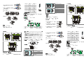
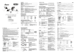
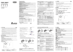
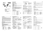
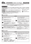
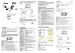
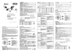
5
Unit: mm
8
3 4 5
Unit: mm
DeviceNet/CANopen sub cable connector
6
Termination resistance setup switch
7
121Ω termination resistance
8
DIN rail
1
DeviceNet/CANopen main cable connector
2
DeviceNet/CANopen main cable connector
3
DeviceNet/CANopen sub cable connector
4
DeviceNet/CANopen sub cable connector
5
DeviceNet/CANopen sub cable connector
6
Termination resistance setup switch
7
121Ω termination resistance
8
DIN rail
Thick Cable
V+
H
H
S
S
L
L
V-
V-
V-
L
S
H
Thick Cable
TB1
V+
L
V-
S
TB2
H
V-
V+
V+
L
S
H
V+
V+
V+
V+
H
H
H
S
S
S
L
L
L
V-
V-
V-
TB3
TB4
TB3
TB5
產品簡介
銘牌說明
Thin Cable
Thin Cable
Thin Cable
Specifications
產品型號
TAP-CN03
管理條碼序號
Electrical Specifications
V+
TB1
T hick Cable
Storage: -25ºC ~ 70ºC (temperature), 5 ~ 95% (humidity)
H
S
L
L
V-
V-
VX.XXXX
MADE IN XXXXXX
序號說明
CN0X000 0 W 7 25 0001
App rox. 3 0mm
8 76 5 4 3 2 1
8 76 5 43 2 1
8 76 5 4 3 2 1
for approx. 30mm. DO NOT damage the shielded
cable while peeling.
產品外觀及各部介紹
Shielded cable
② Peel off the metallic shielded net and foil and you
TB4
TB 3
will see 2 power cables (in red and black), 2 signal
cables (in blue and white) and 1 shielded cable.
Thin Cable
TB5
Thin Cable
66. 50[2.62]
Thin Cable
1
Black (V-)
Blue (CAN_L)
Shielded cable (CAN_SHLD)
holes in the connector in correct order.
Switch off the power before wiring.
This instruction only provides introductory information on electrical specifications, functions, wiring,
trouble-shooting and peripherals for TAP-CN01/02/03.
TAP-CN01/02/03 is an OPEN-TYPE device and therefore should be installed in an enclosure free of airborne dust,
humidity, electric shock and vibration. The enclosure should prevent non-maintenance staff from operating the
device (e.g. key or specific tools are required to open the enclosure) in case danger and damage on the device may
occur.
In order not to damage it, only qualified professional staff familiar with the structure and operation of
Red (V+)
White (CAN_H)
the wiring again before switching on the power and DO NOT touch any terminal when the power is switched on.
Introduction
⑤
Tighten the screws on the connector by a slotted
screwdriver, and fix the communication cables in
the holes in the connector.
Screw by a slotted screwdriver.
⑥
⑦ Mount TAP-CN01/CN02/CN03 onto the DIN rail.
Use standard 35mm DIN rail.
Thank you very much for choosing Delta TAP-CN01/02/03 distribution box. TAP-CN01/02/03 is the distribution
box for the connection of main cable and sub cable in DeviceNet or CANopen. TB1 and TB2 are for connecting
main cables, and TB3 ~ TB5 are for connecting sub cables. TAP-CN01/02/03 formulates a termination
resistance, which is switched by the setup switch.
TAP-C N02
TAP-C N01
TAP -CN0 3
OF F
OF F
Version
Barcode, Serial No.
VX.XXXX
Description
V-
0V DC
L
CAN_L
SignalShielded cable
S
SHIELD
H
CAN_H
Signal+
V+
V+
24V DC
PIN
Signal
Description
1
CAN_H
Signal+
2
CAN_L
Signal-
3
CAN_GND
0V DC
4
RESE_1
Reserved
5
RESE_2
Reserved
6
CAN_SHLD
Shielded cable
7
CAN_GND
0V DC
8
CAN_V+
24V DC
ON
O FF
2
6
1
7
87654321
The termination resistance switch is used for determining whether the resistance is valid.
ON = valid; OFF = invalid.
Connection Example
5
3
8 7.0 0 [3 .4 3 ]
Termination resistance setup switch
5
121Ω termination resistance
6
DIN rail
4
DeviceNet/CANopen
DeviceNet/CANopen
4
功能規格
環境規格
7
8
電壓規格:11 ~ 25V DC(由網路中的電源線提供)
安裝說明
TAP-CN03
② 剝開外層的金屬遮蔽網和鋁箔,你會看到 2 根電源線(紅
色和黑色)、2 根信號線(藍色和白色)、1 根遮蔽線。
Insert the connector into
TAP-CN03 terminal.
Notes:
1. Use only wires specifically designed for DeviceNet/CANopen for wiring.
2. The terminal screws shall be tightened to 5.18 kg-cm (4.5 in-lbs).
3. DO NOT place the signal cable and power cable in the same wiring circuit.
Unit: mm
Main cable
Sub cable
DeviceNet/CANopen sub cable connector
4
TAP-CN01
Sub cable
DeviceNet/CANopen main cable connector
3
Sub cable
Sub cable
Sub cable
2
8
DeviceNet/CANopen
3
① 請使用專業工具將通訊電纜剝開大約 30mm,在剝線過程
中注意不要損壞遮蔽線。
TAP-CN02
Main cable
Main cable
6
6
電氣規格
Establishing a network through TAP-CN01/CN02/CN03:
Sub cable
2
7
主幹線通訊連接器
主幹線通訊連接器
分支線通訊連接器
DeviceNet/CANopen 分支線通訊連接器
DeviceNet/CANopen 分支線通訊連接器
終端電阻設置開關
121Ω終端電阻
DIN 軌槽
1
2
0ºC ~ 55ºC(溫度)、50 ~ 95%(濕度)、污染等級 2
操作/儲存環境 操作:
儲存:-25ºC ~ 70ºC(溫度)、5 ~ 95%(濕度)
Model name
1
2
DeviceNet
Insert the connector into
TAP-CN02 terminal.
Product Profile & Outline
DeviceNet/CANopen main cable connector
8
6
Version No.
1
1
尺寸單位:mm
TAP-CN01/CN02/CN03 formulates a 121Ω termination resistance.
6 6 .5 0 [2 .62 ]
尺寸單位:mm
5
CN0X000 0 W 7 25 0001
Production plant (W: Wujiang T: Taoyuan)
DeviceNet/CANopen
7
5
3 4 5
Serial No. Explanation
Insert the connector into
TAP-CN01 terminal.
DeviceNet/CANopen
3
8 4
66.50[ 2.62]
Production year (2007)
DeviceNet/CANopen
2
5
4
主幹線通訊連接器
主幹線通訊連接器
分支線通訊連接器
DeviceNet/CANopen 分支線通訊連接器
DeviceNet/CANopen 分支線通訊連接器
終端電阻設置開關
121Ω終端電阻
DIN 軌槽
1
6
MADE IN XXXXXX
Production No.
Production week
3
6
96.50[ 3.80]
V+
H
S
L
V-
Termination Resistance
⑧ Insert the connectors into TAP-CN01/CN02/CN03.
R T U D E N T0 0T7 200 001
CN010000W7250001
Signal
V-
DeviceNet/CANopen
5
Termination Resistance Setup Switch
OF F
Nameplate Explanation
Model name
PIN
DeviceNet/CANopen
2
4
尺寸單位:mm
主幹線通訊連接器
主幹線通訊連接器
DeviceNet/CANopen 分支線通訊連接器
終端電阻設置開關
121 Ω終端電阻
DIN 軌槽
1
4
3
TAP-CN01/02/03 can install, operate, wire and repair it.
DO NOT connect input AC power supply to any of the I/O terminals; otherwise serious damage may occur. Check all
3
To connect with the DeviceNet/CANopen network, use the connector enclosed with TAP-CN01/02/03 or any
connectors you can buy in the store for wiring.
ENGLISH
prevent damages on the device or injuries to staff.
6
5
DeviceNet/CANopen Connector
the plastic cover of the power cable and signal cable
in proper length.
④ Insert the peeled communication cables into the
2
Components
③ Peel off the exterior metallic shielded net, foil and
Warning
87.00[3.43]
① Use efficient tool to peel the communication cable
Please read this instruction sheet carefully before use and follow the sheet to operate TAP-CN01//02/03 in order to
製造序號
生產週次
生產年份(2007年)
製造工廠(W: 吳江廠 T:桃園廠)
版本序號
生產機種
121¿
How to Install
版本
UDENT0
200
0 0 11
CNRT
010
000W0T7
725
000
97.00[3.43]
Operation/Storage
Operation: 0ºC ~ 55ºC (temperature), 50 ~ 95% (humidity), pollution degree 2
V+
H
S
TB2
Voltage: 11 ~ 25V DC (supplied by the power cable in the network)
Environment
T hick Cable
DeviceNet
繁體中文
請務必在使用之前仔細閱讀本使用手冊,並按照本手冊指示進行操作,以免造成產品受損,或導致人員受傷。
實施配線,務必關閉電源。
本使用說明書僅提供電氣規格、功能規格、安裝配線、故障排除及周邊裝置部分說明。
本機為開放型 (OPEN TYPE) 機殼,因此使用者使用本機時,必須安裝於具防塵、防潮及免於電擊/衝擊意外
的外殼配線箱內。另必須具備保護措施 (如:特殊的工具或鑰匙才可打開) ,防止非維護人員操作或意外衝擊
本體,造成危險及損壞。請勿在上電時觸摸任何端子。
為避免損壞本產品,只有合格且熟悉本產品結構及操作的專業人員才可進行本產品的安裝、操作、配線及維
護。
交流輸入電源不可連接於輸入/輸出信號端,否則可能造成嚴重損壞。請在上電前再次確認電源配線,且請勿
在上電時觸摸任何端子。本體上的接地端子。
謝謝您使用台達 TAP-CN01/CN02/CN03 分接盒。TAP-CN01/CN02/CN03 定義為 DeviceNet 和 CANopen 分接盒,
用於 DeviceNet 或者 CANopen 主幹線與分支線的連接,TB1 與 TB2 用於連接主幹線,TB3 ~ TB5 用於連接分支
線。TAP-CN01/CN02/CN03 集成一個 121 歐姆的終端電阻,並通過 SW 開關來切換是否有效。
TAP-CN02
66.50[2.62]
6
66.50[2.62]
2
7
DeviceNet/CANopen sub cable connector
5
TAP-CN01
121¿
1
4
注意事項
Electrical Circuit
121¿
66.50[ 2.62]
DeviceNet/CANopen sub cable connector
TB2
4
DeviceNet/CANopen main cable connector
3
Thick Cable
3
8
DeviceNet/CANopen main cable connector
2
TB1
7
1
Thick Cable
2
6
97.00[3.43]
96.50[ 3.80]
1
① To install TAP-CN01/CN02/CN03 in the starting point or end of the network, you have to switch ON the
termination resistance. To install TAP-CN01/CN02/CN03 in the middle of the network, you have to switch
OFF the termination resistance.
② When using TAP-CN01/CN02/CN03 to establish a DeviceNet/CANopen network, the sub cable cannot be
longer than 6m.
③ 去除外層的金屬遮蔽網和鋁箔,然後剝去電源線以及信號
線的塑膠表皮,剝開的長度要適當。
大約 30mm
遮蔽線
腳位
信號
敘述
1
CAN_H
Signal+
2
CAN_L
Signal-
5
6
3
4
7
5
尺寸单位:mm
8
1
OF
F
3
CAN_GND
4
RESE_1
5
RESE_2
6
CAN_SHLD
7
CAN_GND
0V DC
8
CAN_V+
24V DC
ON
O FF
保留
保留
遮蔽線
終端電阻設置開關
終端電阻設置開關
OF
F
⑧ 將通訊連接器插入 TAP-CN01/CN02/CN03。
0V DC
2
1
87654321
6
3 4 5
終端電阻設置開關 SW 用於切換終端電阻是否有效。當 SW 撥至”ON”位置時,終端電阻有效;
當 SW 撥至”OFF”位置時,終端電阻無效。
終端電阻
DeviceNet
集成一個 121Ω終端電阻。
TAP-CN01 主幹線
分
支
線
將通訊連接器插入
TAP-CN03 端子座
主干线通讯连接器
DeviceNet/CANopen 主干线通讯连接器
DeviceNet/CANopen 分支线通讯连接器
DeviceNet/CANopen 分支线通讯连接器
DeviceNet/CANopen 分支线通讯连接器
终端电阻设置开关
121Ω终端电阻
DIN 轨槽
分
支
線
分
支
線
電氣回路
注意事項
TAP-CN01
TAP-CN02
T hic k C ab le
T B1
L
L
V-
V-
TB2
H
S
Thick Ca ble
TB1
T B2
V+
H
V-
L
S
H
V+
V-
V+
121¿
V-
L
S
H
L
S
H
V+
1 21 ¿
Thick Ca ble
V+
S
V+
TB3
V+
V+
H
H
H
S
S
S
L
L
L
V-
V-
V-
T B3
T B4
T B5
T hin C a ble
T hin C a ble
Thin Cable
H
S
S
L
L
V-
V-
安裝說明
8 76 5 43 2 1
TB3
TB4
TB5
Thin Cable
Thin Cable
通訊連接器
产品外观及各部介绍
與 DeviceNet/CANopen 網路連接,可使用 TAP-CN01/CN02/CN03 隨機附帶的連接器或市售的連接器進行配線。
6 6 .5 0 [2 .6 2 ]
2
1
2
5
3
V+
4
尺寸单位:mm
3
6
4
5
6
L
S
H
V+
V+
V+
V+
H
H
H
S
S
S
L
L
V-
V-
T B4
T B5
T hin C a ble
T hin C a ble
V+
H
H
S
S
L
L
V-
V-
8765 43 21
TB3
TB4
TB5
Thin Cable
Thin Cable
Thin Cable
通讯连接器
与 DeviceNet/CANopen 网络连接,可使用 TAP-CN01/CN02/CN03 随机附带的连接器或市售的连接器进行配线。
蓝色( CAN_L)
屏蔽线( CAN_SHLD)
TAP-CN02
脚位
黑色( V- )
使用标准的一字起子旋紧
TAP-CN03
将通讯连接器插入
TAP-CN02 端子座
将通讯连接器插入
TAP-CN01 端子座
0V DC
CAN_L
Signal-
S
SHIELD
H
CAN_H
Signal+
V+
V+
24V DC
信号
叙述
1
CAN_H
Signal+
2
CAN_L
Signal-
3
CAN_GND
0V DC
4
RESE_1
5
RESE_2
6
CAN_SHLD
7
CAN_GND
0V DC
8
CAN_V+
24V DC
保留
保留
屏蔽线
终端电阻设置开关
终端电阻设置开关
8 7 6 54 321
终端电阻设置开关 SW 用于切换终端电阻是否有效。当 SW 拨至”ON”位置时,终端电阻有效;
当 SW 拨至”OFF”位置时,终端电阻无效。
终端电阻
集成一个 121Ω终端电阻。
連接範例
下图是通过 TAP-CN01/CN02/CN03 组建的一个网络。
分支线
将通讯连接器插入
TAP-CN03 端子座
V+
H
S
L
V-
屏蔽线
脚位
主干线
DeviceNet/CANopen
叙述
V-
L
ON
O FF
信号
V-
OF F
OF F
注意事项:
配线请使用 DeviceNet/CANopen 专用线材。
配线端子镙丝扭力为 5.18 kg-cm (4.5 Ib-in)。
3. 在配线时请勿将信号线与电源动力线置于同一线糟内。
8765 432 1
各部分元件介紹
DeviceNet/CANopen
⑧ 将通讯连接器插入 TAP-CN01/CN02/CN03。
主干线通讯连接器
DeviceNet/CANopen 主干线通讯连接器
DeviceNet/CANopen 分支线通讯连接器
终端电阻设置开关
121Ω终端电阻
DIN 轨槽
V-
V+
V-
TAP-CN01/CN02/CN03
8 7.0 0 [3 .4 3 ]
各部分元件介紹
DeviceNet/CANopen
TAP-CN01
制造序号
生产周次
生产年份( 2007年)
制造工厂( W:吴江厂 T:桃园厂)
版本序号
生产机种
1
CN0X000 0 W 7 25 0001
8 76 5 43 2 1
Thin Cable
H
屏蔽线
MADE IN XXXXXX
1 21¿
8 76 5 43 2 1
S
8 76 5 4 3 2 1
序号说明
L
大约 30mm
⑥ 请使用 35mm 的标准 DIN 轨。
⑦ 将 TAP-CN01/CN02/CN03 固定在 DIN 轨上,如下图所示。
UDENT0
200
0 0 11
CNRT
010
000W0T7
725
000
H
Thin Cable
⑤ 使用标准的一字起子旋紧通讯连接器的螺丝,将通讯电缆
固定于通讯连接器的线孔内。
版本
产品型号
TB2
S
L
红色( V+)
白色( CAN_H)
VX.X XXX
V-
L
T B3
OF F
管理条码序号
TB2
V+
H
Thick Cable
TB1
Thick Cable
V+
L
V-
V-
V+
④ 将剥开的通讯电缆按照正确的顺序嵌入通讯连接器的线
孔内,如下图所示。
產品簡介
铭牌说明
L
电压规格:11 ~ 25V DC(由网络中的电源线提供)
简体中文
请务必在使用之前仔细阅读本使用手册,并按照本手册指示进行操作,以免造成产品受损,或导致人员受伤。
实施配线,务必关闭电源。
本使用说明书仅提供电气规格、功能规格、安装配线、故障排除及周边装置部分说明。
本机为开放型 (OPEN TYPE) 机壳,因此使用者使用本机时,必须安装于具防尘、防潮及免于电击/冲击意外
的外壳配线箱内。另必须具备保护措施 (如:特殊的工具或钥匙才可打开) ,防止非维护人员操作或意外冲击
本体,造成危险及损坏。请勿在上电时触摸任何端子。
为避免损坏本产品,只有合格且熟悉本产品结构及操作的专业人员才可进行本产品的安装、操作、配线及维
护。
交流输入电源不可连接于输入/输出信号端,否则可能造成严重损坏。请在上电前再次确认电源配线,且请勿
在上电时触摸任何端子。本体上的接地端子。
谢谢您使用台达 TAP-CN01/CN02/CN03 分接盒。TAP-CN01/CN02/CN03 定义为 DeviceNet 和 CANopen 分接盒,
用于 DeviceNet 或者 CANopen 主干线与分支线的连接,TB1 与 TB2 用于连接主干线,TB3 ~ TB5 用于连接分支
线。 TAP-CN01/CN02/CN03 集成一个 121 欧姆的终端电阻,并通过 SW 开关来切换是否有效。
TAP-CN03
S
TB3
③ 去除外层的金属屏蔽网和铝箔,然后剥去电源线以及信号
线的塑料表皮,剥开的长度要适当。
T hic k C ab le
H
TAP-CN03
② 剥开外层的金属屏蔽网和铝箔,你会看到 2 根电源线(红
色和黑色)、2 根信号线(蓝色和白色)、1 根屏蔽线。
① 如果將 TAP-CN01/CN02/CN03 分接盒安裝在網路的起點或者終點,必須接通終端電阻(將開關設置為”ON”);
如果將 TAP-CN01/CN02/CN03 分接盒安裝在網路的中間位置,需要關閉終端電阻(將開關設置為”OFF”)。
② 如果選用 TAP-CN01/CN02/CN03 分接盒用來組建 DeviceNet/CANopen 網路,所接出的分支線長度不能超過 6m。
2.
H
S
V-
1.
V+
DeviceNet/CANopen
① 请使用专业工具将通讯电缆剥开大约 30mm,在剥线过程
中注意不要损坏屏蔽线。
TAP-CN03
T hic k C ab le
T B1
V+
121¿
分支線 分支線
环境规格
TAP-CN02
T hic k C ab le
0ºC ~ 55ºC(温度)、50 ~ 95%(湿度)、污染等级 2
操作/储存环境 操作:
储存:-25ºC ~ 70ºC(温度)、5 ~ 95%(湿度)
連接範例
分支線
7
8
功能規格
电气规格
主幹線 TAP-CN02 主幹線
4
5
下圖是通過 TAP-CN01/CN02/CN03 組建立一個網路。
注意事項:
注意事項:
配線請使用 DeviceNet/CANopen 專用線材。
配線端子鏍絲扭力為 5.18 kg-cm (4.5 Ib-in)。
3. 在配線時請勿將信號線與電源動力線置於同一線糟內。
6
7
3
8
尺寸单位:mm
TAP-CN01/CN02/CN03
將通訊連接器插入
TAP-CN02 端子座
2
TAP-CN01
TB2
24V DC
4
電氣回路
Thick Cable
Signal+
V+
DeviceNet/CANopen
TB2
CAN_H
8
DeviceNet/CANopen
3
Thick Cable
H
V+
7
DeviceNet/CANopen
2
TB1
TAP-CN03
OF
F
將通訊連接器插入
TAP-CN01 端子座
遮蔽線
主干线通讯连接器
主干线通讯连接器
分支线通讯连接器
DeviceNet/CANopen 分支线通讯连接器
DeviceNet/CANopen 分支线通讯连接器
终端电阻设置开关
121Ω终端电阻
DIN 轨槽
1
Thick Cable
SHIELD
2
6
1
TB1
S
V+
H
S
L
V-
1 21¿
TAP-CN02
TAP-CN01
Signal-
66.50[2.6 2]
使用標準的一字起子旋緊
⑥ 請使用 35mm 的標準 DIN 軌。
⑦ 將 TAP-CN01/CN02/CN03 固定在 DIN 軌上,如下圖所示。
96.50[3.80]
0V DC
CAN_L
121¿
⑤ 使用標準的一字起子旋緊通訊連接器的螺絲,將通訊電纜
固定於通訊連接器的線孔內。
敍述
V-
L
Thick Cable
紅色(V+)
白色(CAN_H)
信號
V-
97.00[ 3.43]
腳位
黑色(V-)
66.5 0[2.62]
藍色(CAN_L)
遮蔽線(CAN_SHLD)
④ 將剝開的通訊電纜按照正確的順序嵌入通訊連接器的線孔
內,如圖所示。
TAP-CN02
主干线
分支线 分支线
TAP-CN01
分
支
线
主干线
TAP-CN03
分
支
线
分
支
线
1.
2.
① 如果将 TAP-CN01/CN02/CN03 分接盒安装在网络的起点或者终点,必须接通终端电阻(将开关设置为”ON”);
如果将 TAP-CN01/CN02/CN03 分接盒安装在网络的中间位置,需要关闭终端电阻(将开关设置为”OFF”)。
② 如果选用 TAP-CN01/CN02/CN03 分接盒用来组建 DeviceNet/CANopen 网络,所接出的分支线长度不能超过 6m。