1
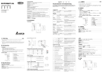
Y Specifications after the communication parameters are set. Parameter Function Setting up source of frequency P00-20 command Setting up source of operation P00-21 command DeviceNet Connector 5-PIN open removable connector. Of 5.08mm PIN interval Transmission method CAN Transmission cable Shielded twisted pair cable (with 2 power cables) P09-30 Decoding method for communication 0 Transmission speed 125kbps, 250kbps, 500kbps and extendable serial transmission speed mode P09-70 User defined Network protocol DeviceNet protocol P09-71 Node address of communication card Serial transmission speed of communication card Setting up mode for P09-71 User defined P09-72 Interface 50 PIN communication terminal Transmission method SPI communication Terminal function 1. Communicating with AC motor drive 2. Transmitting power supply from AC motor drive Communication protocol Delta HSSP protocol P09-70 is changed, please shut down C2000 and re-power it to make the parameter valid. Power consumption 1W Weight 23g Builder software to configure the DeviceNet network. ESD (IEC 61800-5-1,IEC 6100-4-2) EFT (IEC 61800-5-1,IEC 6100-4-4) Surge Test (IEC 61800-5-1,IEC 6100-4-5) Conducted Susceptibility Test (IEC 61800-5-1,IEC 6100-4-6) Noise immunity Shock / vibration Z Installation DeviceNet Connector Signal Color AO Definition 1 V+ Red DC24V 2 CAN_H White Signal+ 1 3 S - Earth 4 CAN_L Blue Signal- 5 5 V- Black 0V How to Install X Introduction Thank you for choosing Delta CMC-DN01 network communication card. CMC-DN01 is a DeviceNet network communication card for connecting Delta C2000 series, CH2000 series, CP2000 series, CT2000 series, and AFE2000 series AC motor drives to DeviceNet network. Functions Shielded cable ② Peel off the metallic shielded net and foil and you will (in blue and white) and 1 shielded cable. Setting value 52 52 52 22 22 Address 2600h 2640h 2660h 2661h 2662h 26A0h 26A1h Number Bit 0 Bit 1 Bit 2 I/O on the FWD REV MI1 control panel EMC-D611A EMC-D42A - 產品外觀 R/W R RW R R R RW RW Address length b15~b0 b15~b0 b15~b0 b15~b0 b15~b0 b15~b0 b15~b0 Description Digital inputs b15~b0 Digital outputs b15~b0 Percentage of AVI analog input signals Percentage of ACI analog input signals Percentage of AUI analog input signals Percentage of AFM1 analog output signals Percentage of AFM2 analog output signals Bit 3 Bit 4 Bit 5 Bit 6 Bit 7 Bit 8 Bit 9 Bit 10 Bit 11 Bit 12 Bit 13 Bit 14 Bit15 MI2 MI3 MI4 MI5 MI6 MI7 MI8 - - - - - - - - - - - - - MI10 MI11 MI12 MI13 MI14 MI15 MI10 MI11 MI12 MI13 [圖 1] proper length. Blue (CAN_L) Black (V-) Shielded cable (CAN_SHLD) in the connector in correct order. [Figure 5] Red (V+) White (CAN_H) ⑤ Tighten the screws on the connector by a slotted screwdriver, and fix the communication cables in the holes in the connector. [Figure 6] [Figure 7] [ LED Indicator & Troubleshooting Screw by a slotted screwdriver ⑥ Install CMC-DN01 on C2000: 2. Open the cover on top of C2000. positioning pin. Press the pin to clip the holes with the PCB (see Figure 2). 4. Screw up at torque 6~8 kg-cm (5.21~6.94 in-lbs) after the PCB is clipped with the holes (see Figure 3). Indication 5. DeviceNet connection port 6. Screw fixing hole 7. Fool-proof groove 8. AC motor drive connection port Power supply in abnormal status. Check the power supply of CMC-DN01. Off Power supply in normal status -- NS LED LED status Red light on When C2000 is connected to DeviceNet, please set up the communication parameters for it according to the table below. The DeviceNet master is only able to read/write the frequency word and control word of C2000 Y 功能規格 DeviceNet 連接埠 接頭 5 針開放式可插拔連接頭,腳位間隔 5.08mm 傳輸方式 CAN 傳輸電纜 遮罩式雙絞線(帶兩條電源線) 傳輸速率 125kbps、250kbps、500kbps 及擴展串列傳輸速率模式 網路協議 DeviceNet 協議 交流馬達驅動器連接埠 50 PIN 通訊端子 接頭 Indication No power supply or CMC-DN01 has not completed MAC ID test yet. CMC-DN01 is on-line but has not established connection to the master. CMC-DN01 is on-line and is normally connected to the master CMC-DN01 is on-line, but I/O connection is timed-out. 1. 2. 3. 4. The communication is down. MAC ID test failure. No network power supply. CMC-DN01 is off-line. How to correct 1. Check the power of CMC-DN01 and see if the connection is normal. 2. Make sure at least one or more nodes are on the bus. 3. Check if the serial transmission speed of CMC-DN01 is the same as that of other nodes. 1. Configure CMC-DN01 to the scan list of the master. 2. Re-download the configured data to the master. 1. Check if the network connection is normal. 2. Check if the master operates normally. 1. Make sure all the MAC IDs on the network are not repeated. 2. Check if the network installation is normal. 3. Check if the baud rate of CMC-DN01 is consistent with that of other nodes. 4. Check if the node address of CMC-DN01 is illegal. 5. Check if the network power supply is normal. 台達 HSSP 協議 電源電壓 5VDC(由交流馬達驅動器提供) 絕緣電壓 500VDC 通訊線電力消耗 0.85W 電力消耗 1W 重量 23g 環境規格 雜訊免疫力 ESD (IEC 61800-5-1,IEC 6100-4-2) EFT (IEC 61800-5-1,IEC 6100-4-4) Surge Teat(IEC 61800-5-1,IEC 6100-4-5) Conducted Susceptibility Test(IEC 61800-5-1,IEC 6100-4-6) 操作∕儲存環境 操作:-10°C ~ 50°C(溫度),90%(濕度) 儲存:-25°C ~ 70°C(溫度),95%(濕度) 耐震動∕衝擊 國際標準規範 IEC61131-2, IEC68-2-6 (TEST Fc) / IEC61131-2 & IEC 68-2-27(TEST Ea) Z 安裝 Indication How to correct No power supply or being off-line Check the power supply of CMC-DN01 and see of the connection is normal. Green light flashes Waiting for I/O data Switch the master PLC to RUN status Green light on I/O data are normal -- Red light flashes 1. Reconfigure CMC-DN01 2. Re-power AC motor drive 1. See the error code displayed on AC motor drive. Hardware error 2. Send back to the factory for repair if necessary. If the flashing lasts for a long time, check if CMC-DN01 CMC-DN01 is establishing connection with and AC motor drive are correctly installed and normally AC motor drive. connected to each other. Orange light flashes 2. 交流馬達驅動器通過該介面給通訊卡提供電源 電氣規格 -- Off Red light on SPI 通訊 1. 通訊卡通過該介面與交流馬達驅動器通訊 How to correct On LED status 4. Positioning hole 6. 螺絲固定孔 8. 交流馬達驅動器連接埠 通訊協議 MS LED 3. POWER indicator 5. DeviceNet 連接埠 7. 通訊卡防呆溝槽 POWER LED Green light on Communication Parameters for C2000 Connected to DeviceNet 4. 通訊卡定位孔 端子功能 Green light flashes [Figure 4] 3. POWER 指示燈 LED are dual-color LED, displaying the connection status of the communication and error messages. Off Figure4) 2. MS 指示燈 There are 3 LED indicators on CMC-DN01. POWER LED displays the status of power supply. MS LED and NS LED status 1. Switch off the power supply of C2000. 1. NS 指示燈 傳輸方式 [Figure 2] [Figure 3] ⑦ Connect to DeviceNet connector: Insert the connector to the connection port on CMC-DN01 (see 2. MS indicator 功能特色 6. 通訊站號和串列傳輸速率可直接在交流馬達驅動器上設定 Disconnecting CMC-DN01 from C2000 Red light flashes 1. NS indicator X 產品簡介! 7. 通訊卡可自動從交流馬達驅動器獲得工作電源 plastic cover of the power cable and signal cable in Product Profile [Figure 1] 務必正確的接地,以提高產品抗干擾能力。 5. 支援 DeviceNet 匯流排的所有通訊速率:125kbps、250kbps、500kbps 及擴充串列傳輸速率模式。 ③ Peel off the exterior metallic shielded net, foil and the 3. Place the insulation spacer into the positioning pin, and aim the two holes on the PCB at the 1. Based on the high-speed communication interface of Delta HSSP protocol, able to conduct immediate control to AC motor drive. 2. Supports Group 2 only connection and polling I/O data exchange. 3. For I/O mapping, supports Max. 32 words of input and 32 words of output. 4. Supports EDS file configuration in DeviceNet configuration software. 5. Supports all baud rates on DeviceNet bus: 125kbps, 250kbps, 500kbps and extendable serial transmission speed mode. 6. Node address and serial transmission speed can be set up on AC motor drive. 7. Power supplied from AC motor drive. 勿在上電時觸摸任何端子。本體上的接地端子 4. 支援在 DeviceNet 配置工具軟體裡使用 EDS 檔進行配置 Parameter 02-13~02-15 02-16~02-17 02-36~02-41 03-20 03-23 After C2000 is shut down, remove the two screws (as Figure 5) to twist open the card clip (as Figure 6). Insert the slot type screwdriver to the hollow and prize the PCB off the card clip. Twist open the other card clip (as Figure 7) to remove the PCB. see 2 power cables (in red and black), 2 signal cables ④ Insert the peeled communication cables into the holes 交流輸入電源不可連接於輸入∕輸出信號端,否則可能造成嚴重損壞。請在上電前再次確認電源配線,且請 Number Bit 0 Bit 1 Bit 2 Bit 3 Bit 4 Bit 5 Bit 6 Bit 7 Bit 8 Bit 9 Bit 10 Bit 11 Bit 12 Bit 13 Bit 14 Bit15 I/O on the control RY1 RY2 MO1 MO2 panel EMC-D42A - MO10 MO11 EMC-R6AA RY10 RY11 RY12 RY13 RY14 RY15 - while peeling. EN a CMC-DN01 is an OPEN-TYPE device. It should be installed in a control cabinet free of airborne dust, humidity, electric shock and vibration. To prevent non-maintenance staff from operating CMC-DN01, or to prevent an accident from damaging CMC-DN01, the control cabinet in which CMC-DN01 is installed should be equipped with a safeguard. For example, the control cabinet in which CMC-DN01 is installed can be unlocked with a special tool or key. EN a DO NOT connect AC power to any of I/O terminals, otherwise serious damage may occur. Please check all wiring again before CMC-DN01 is powered up. After CMC-DN01 is disconnected, Do NOT touch any terminals in a on CMC-DN01 is correctly grounded in order to prevent minute. Make sure that the ground terminal electromagnetic interference. FR a CMC-DN01 est un module OUVERT. Il doit être installé que dans une enceinte protectrice (boitier, armoire, etc.) saine, dépourvue de poussière, d’humidité, de vibrations et hors d’atteinte des chocs électriques. La protection doit éviter que les personnes non habilitées à la maintenance puissent accéder à l’appareil (par exemple, une clé ou un outil doivent être nécessaire pour ouvrir a protection). FR a Ne pas appliquer la tension secteur sur les bornes d’entrées/Sorties, ou l’appareil CMC-DN01 pourra être endommagé. Merci de vérifier encore une fois le câblage avant la mise sous tension du CMC-DN01. Lors de la déconnection de l’appareil, ne pas toucher les connecteurs dans la minute suivante. Vérifier que la terre est bien afin d’éviter toute interférence électromagnétique. reliée au connecteur de terre 輸入電源切斷後,一分鐘之內,請勿觸摸內部電路。 Correspondence for the address 2640: Approx. 30mm approx. 30mm. DO NOT damage the shielded cable ENGLISH 3 3 Correspondence for the address 2600: 2 3 4 ① Use efficient tool to peel the communication cable for Terminal DI DO AI Note: The contents below are about installing CMC-DN01 on C2000. PIN 衝擊意外之外殼配線箱內。另必須具備保護措施(如:特殊之工具或鑰匙才可打開),防止非維護人員操作 或意外衝擊本體,造成危險及損壞。 2. Control addresses International standards: IEC61131-2, IEC68-2-6 (TEST Fc)/IEC61131-2 & IEC 68-2-27 (TEST Ea) resistance 本機為開放型 (OPEN TYPE) 機殼,因此使用者使用本機時,必須將之安裝於具防塵、防潮及免於電擊∕ 3. I/O 映射最 大支持 32 字輸入,32 字輸出。 *Relay3 is for CP2000. MO1~MO2 are for C2000/CH2000. Operation: -10ºC ~ 50ºC (temperature), 90% (humidity), pollution degree 2 Storage: -25ºC ~ 70ºC (temperature), 95% (humidity, non-condensing) Operation /storage 配線時請務必關閉電源,請勿在上電時觸摸任何端子。 2. 支援 Group 2 only 連接方式,支援輪詢 I/O 資料交換。 1. Controlling the setting by a control card Multi-function output terminal Relay1~Relay3* MO1~MO2 MO10~MO15(RY10~RY15) AFM1 AFM2 此安裝手冊只提供電氣規格、一般規格、安裝及配線等。 1. 基於台達 HSSP 協定的高速通訊介面,可對交流馬達驅動器進行即時控制。 Controlling and Using the I/O on an AC Motor Drive by a Communication Card Environment 3 3 3 繁体中文 CH2000、CP2000、CT2000 及 AFE2000 系列交流馬達 驅動器接入 DeviceNet 網路。 DVPDNET-SL is the DeviceNet master, and CMC-DN01 and C2000 construct DeviceNet slave. Use DeviceNet 0.85W power consumption 注意事項 感謝您使用台達 CMC-DN01 網路通 訊卡。CMC-DN01 定義為 DeviceNet 網路通訊卡,用於將台達 C2000、 Constructing DeviceNet Network 500VDC Communication wire User defined C2000 during configuration. Changing the value in P09-70 when C2000 is working will be invalid. After the value in 5VDC (supplied by AC motor drive) Insulation voltage 5 Note: The value of P09-70 is the address of C2000 in DeviceNet. The address has to be consistent with the address of Electrical Specification Power supply voltage Explanation The frequency command is controlled by the communication card. The operation command is controlled by the communication card. The old decoding method for the Delta AC motor drive Node address of C2000 in DeviceNet. Serial transmission speed of C2000 in DeviceNet. When P09-72 = 0, P09-71 will enter standard mode. When P09-72 = 1, P09-71 will enter extension mode. 8 Interface AC Motor Drive Connection Port Warning Set value Mapping error 註:以下內容僅以 C2000 示意。 DeviceNet 連接埠腳位定義 腳 位 訊 號 顏 色 敘 述 1 V+ 紅色 DC24V 1 2 CAN_H 白色 正信號線 2 3 4 5 3 S - 接地線 4 CAN_L 藍色 負信號線 5 V- 黑色 0V [ LED 燈指示說明及故障排除 安裝連接說明 大約 30m m ① 請使用專業工具將通訊電纜剝開大約 30mm,在剝線過程中 注意不要損壞遮蔽線。 是雙色 LED,用來顯示通訊卡的通訊連接狀態及錯誤資訊。 遮蔽線 ② 剝開外層的金屬遮蔽網和鋁箔,你會看到 2 根電源線(紅色 和黑色)、2 根信號線(藍色和白色)、1 根遮蔽線。 POWER LED 燈顯示說明 LED 燈狀態 ③ 去除外層的金屬遮蔽網和鋁箔,然後剝去電源線以及信號線 的塑膠表皮,剝開的長度要適當。 黑色 ( V-) 藍色 ( C A N _L ) 遮蔽線 ( C AN _S H L D ) ④ 將剝開的通訊電纜按照正確的順序嵌入通訊連接器的線孔 內,如圖所示。 顯示說明 工作電源不正常 檢查 CMC-DN01 工作電源是否正常 綠燈亮 工作電源正常 無需處理 LED 燈狀態 ⑤ 使用標準的一字起子旋緊通訊連接器的螺絲,將通訊電纜固 定於通訊連接器的線孔內。 顯示說明 處理方法 1. 檢查 CMC-DN01 的電源,檢查線路是否連接正常。 2. 確認匯流排上存在一個以上的節點設備 3. 檢查 CMC-DN01 的串列傳輸速率是否與其他節點設 備一致 綠燈閃爍 綠燈亮 CMC-DN01 已經在線上,並且與主站的連接 正常。 無需處理 紅燈閃爍 CMC-DN01 已經在線上,但 I/O 連接超時。 1. 檢查網路連接是否正常 2. 檢查主站是否正常運行 [圖 4] 传输方式 CAN ࿅఼ੈΙଠֹטϡតᐛጡ I/O 传输电缆 屏蔽式双绞线(带两条电源线) 1. 提供控制卡控制设定 传输速率 125kbps、250kbps、500kbps 及扩展波特率模式 网络协议 DeviceNet 协议 LED 燈狀態 主站才可以對台達 C2000 Driver 的頻率字元組和控制字元組進行讀寫操作。 燈滅 參數設定值 顯示說明 處理方法 等待 I/O 數據 將主站 PLC 切換至 RUN 狀態 綠燈亮 I/O 資料正常 無需處理 紅燈閃爍 映射出錯 1. 重置 CMC-DN01 2. 交流馬達驅動器重新上電 P00-20 頻率指令來源設定 8 P00-21 運轉指令來源設定 5 運轉命令由通訊卡控制 P09-30 通訊解碼方式 0 台達交流馬達驅動器舊的解碼方式 P09-70 通訊卡節點位址 自行設定 交流馬達驅動器在 DeviceNet 中的節點地址 P09-71 通訊卡串列傳輸速率 自行設定 交流馬達驅動器在 DeviceNet 中的串列傳輸速率 紅燈亮 硬體錯誤 P09-72 設置 P9-71 的模式 自行設定 當 P9-72 的值為 0,P9-71 進入標準模式; 當 P9-72 的值為 1,P9-71 進入擴展模式。 1. 參考交流馬達驅動器顯示的錯誤碼,找出錯誤原因。 2. 如有必要,請送回工廠維修。 橙色閃爍 CMC-DN01 正在與交流馬達驅動器建立連接 如長時間閃爍橙色燈,請斷電檢查 CMC-DN01 與交流 馬達驅動器是否正確安裝,連接是否正常。 22 端子功能 1. 通讯卡通过该接口与交流电机驱动器通讯 *Relay3 for CP2000;MO1~MO2 for C2000/CH2000 2. 交流电机驱动器通过该接口给通讯卡提供电源 2. 控制地址 台达 HSSP 协议 通讯协议 5VDC(由交流电机驱动器提供) 绝缘电压 500VDC 通讯线电力消耗 0.85W 电力消耗 1W 重量 23g 操作:-10°C ~ 50°C(温度),90%(湿度) 储存:-25°C ~ 70°C(温度),95%(湿度) 国际标准规范 IEC61131-2, IEC68-2-6 (TEST Fc) / IEC61131-2 & IEC 68-2-27(TEST Ea) CAN_H 白色 正信号线 2 3 4 5 組建 DeviceNet 網路 Relay1~Relay3* 02-13~ 02-15 MO1~MO2 02-16~02-17 MO10~MO15(RY10~RY15) 02-36~02-41 AFM1 03-20 AFM2 03-23 *Relay3 for CP2000;MO1~MO2 for C2000/CH2000 2. 控制位址 端子 位址 位址長度 外冲击本体,造成危险及损坏。 3 交流输入电源不可连接于输入/输出信号端,否则可能造成严重损坏。请在上电前再次确认电源配线,且请 务必正确的接地,以提高产品抗干扰能力。 X யݡᖎ̬ R b15~b0 數位輸入 b15~b0 RW b15~b0 數位輸出 b15~b0 2660h R b15~b0 類比輸入訊號 AVI 百分比 感谢您使用台达 CMC-DN01 网络通讯卡。CMC-DN01 通讯卡定义为 DeviceNet 网络通讯卡,用于将台达 C2000、 CH2000、CP2000、CT2000 及 AFE2000 系列交流电机 驱动器接入 DeviceNet 网络。 AO b15~b0 類比輸入訊號 ACI 百分比 R b15~b0 類比輸入訊號 AUI 百分比 26A0h RW b15~b0 類比輸出訊號 AFM1 百分比 26A1h RW b15~b0 類比輸出訊號 AFM2 百分比 Bit 0 Bit 1 Bit 2 Bit 3 Bit 4 Bit 5 Bit 6 Bit 7 Bit 8 Bit 9 REV MI1 MI2 MI3 MI4 MI5 MI6 MI7 MI8 - - - - - - Bit 10 Bit 11 Bit 12 Bit 13 Bit 14 Bit15 EMC-D611A - - - - - - - - - - MI10 MI11 MI12 MI13 MI14 MI15 EMC-D42A - - - - - - - - - - MI10 MI11 MI12 MI13 - - 位址 2640 對應關係如下: 編號 Bit 0 Bit 1 Bit 2 Bit 3 Bit 4 Bit 5 Bit 6 Bit 7 Bit 8 Bit 9 控制板 I/O RY1 RY2 - MO1 MO2 - - - - - - - - - - - EMC-D42A - - - - - MO10 MO11 - - - - - - - - - EMC-R6AA - - - - - RY10 RY11 RY12 RY13 RY14 RY15 - - - - - V- 黑色 0V Bit 10 Bit 11 Bit 12 Bit 13 Bit 14 Bit15 R b15~b0 模拟输入讯号 ACI 百分比 2662h R b15~b0 模拟输入讯号 AUI 百分比 26A0h RW b15~b0 模拟输出讯号 AFM1 百分比 26A1h RW b15~b0 模拟输出讯号 AFM2 百分比 Bit 0 Bit 1 Bit 2 Bit 3 Bit 4 Bit 5 Bit 6 Bit 7 Bit 8 Bit 9 REV MI1 MI2 MI3 MI4 MI5 MI6 MI7 MI8 Bit 10 Bit 11 Bit 12 Bit 13 Bit 14 Bit15 - - - - - - EMC-D611A - - - - - - - - - - MI10 MI11 MI12 MI13 MI14 MI15 EMC-D42A - - - - - - - - - - MI10 MI11 MI12 MI13 - - 编号 Bit 0 Bit 1 Bit 2 Bit 3 Bit 4 Bit 5 Bit 6 Bit 7 Bit 8 Bit 9 控制板 I/O RY1 RY2 - MO1 MO2 - - - - - - - - - - - EMC-D42A - - - - - MO10 MO11 - - - - - - - - - EMC-R6AA - - - - - RY10 RY11 RY12 RY13 RY14 RY15 - - - - - Bit 10 Bit 11 Bit 12 Bit 13 Bit 14 Bit15 凹陷处,将 PCB 撬开脱离卡勾,最后如[图 7]所示将另一卡勾扳开后,将 PCB 取出。 大約 30m m 遮蔽線 ② 剥开外层的金属屏蔽网和铝箔, 你会看到 2 根电源线(红 色和黑色)、2 根信号线(蓝色和白色)、1 根屏蔽线。 [图 5] [图 6] [图 7] [ LED ፶ϯᄲ߇̈́ځᅪଵੵ 黑色 ( V- ) 藍色 ( C A N _L ) ④ 将剥开的通讯电缆按照正确的顺序嵌入通讯连接器的线孔 遮蔽線 ( C AN _S H L D ) CMC-DN01 通讯 卡有三个 LED 指示灯。POWER LED 用来显示通讯卡的工作电源是否正常;MS LED、NS LED 内,如图所示。 是双色 LED,用来显示 CMC-DN01 的通讯连接状态及错误信息。 LED 灯状态 固定于通讯连接器的线孔内。 1. 关闭交流电机驱动器电源。 显示说明 工作电源不正常 检查 CMC-DN01 工作电源是否正常 绿灯亮 工作电源正常 无需处理 NS LED ፶ពϯᄲځ 1. 基于台达 HSSP 协议的高速通讯接口,可对交流电机驱动器进行实时控制。 3. 将绝缘片放入定位柱,再将 PCB 上两个圆孔对准定位柱后下压,让两个卡勾卡住 PCB,如[图 2]所示。 2. 支持 Group 2 only 连接方式,支持轮询 I/O 数据交换。 4. PCB 上两个卡勾卡住 PCB 后,将螺丝锁上,扭力为 6~8 kg-cm (5.21~6.94 in-lbs),如[图 3]所示。 3. I/O 映射最 大支持 32 字输入,32 字输出。 LED 灯状态 显示说明 5. 支持 DeviceNet 总线的所有通讯速率:125kbps、250kbps、500kbps 及扩展波特 率模式。 6. 通讯站号和波特率直接在交流电机驱动器上设定。 7. 自动从交流电机驱动器获得工作电源。 [图 2] [图 3] [图 4] 灯灭 没有工作电源或 MAC ID 检测不通过 绿灯闪烁 CMC-DN01 已经在线,但没有与主站建立连接。 1. 将 CMC-DN01 配置到主站扫描列表 2. 重新下载配置数据至主站 绿灯亮 CMC-DN01 已经在线,并且与主站的连接正常。 无需处理 红灯闪烁 CMC-DN01 已经在线,但 I/O 连接超时。 1. 检查网络连接是否正常 2. 检查主站是否正常运行 红灯亮 通讯中断; MAC ID 检测失败; 无网络电源; CMC-DN01 离线。 1. 2. 3. 4. 5. ⑦ 连接 DeviceNet 通讯连接器:将通讯连接器按 [图 4] 箭头所示的 方向插入 CMC-DN01 的连 接口。 C2000 ତˢ DeviceNet შඛॡ۞఼ੈણᇴన!ؠ 台达 C2000 Driver 接入 DeviceNet 网络时,须根据表格设置交流电机驱动器的通讯参数。设置通訊参数后, 参数 凹陷處,將 PCB 撬開脫離卡勾,最後如[圖 7]所示將另一卡勾扳開後,將 PCB 取出。 [图 1] 1. NS 指示灯 2. MS 指示灯 3. POWER 指示灯 4. 通讯卡定位孔 5. DeviceNet 连接口 6. 螺丝固定孔 7. 通讯卡防呆沟槽 8. 交流电机驱动器连接口 参数说明 参数设定值 参数设定值含义 处理方法 1. 检查 CMC-DN01 的电源,检查线路是否连接正常。 2. 确认总线上存在一个以上的节点设备 3. 检查 CMC-DN01 的波特率是否与其它节点设备一致 4. 支持在 DeviceNet 配置工具软体里使用 EDS 文件进行配置。 யݡγ៍ 处理方法 灯灭 DeviceNet 主站才可以对台达 C2000 Driver 的频率字和控制字进行读写操作。 [圖 7] 2661h щ྅ాତᄲ!ځ ⑥ 将 CMC-DN01 安装于 C2000 系列交流电机驱动器上,如下图所示。 關閉交流馬達驅動器電源後,將兩顆螺絲拆下,如[圖 5]所示,再如[圖 6]所示將卡勾扳開後,以一字起子斜插入 [圖 6] 5 使用標準的一字起子旋緊 CMC-DN01 從 C2000 系列交流馬達驅動器上卸除 [圖 5] 负信号线 2. 打开交流电机驱动器上盖。 控制板 I/O FWD 編號 接地线 蓝色 ⑤ 使用标准的一字起子旋紧通讯连接器的螺丝,将通讯电缆 ΑਕপҒ 位址 2600 對應關係如下: 模拟输入讯号 AVI 百分比 POWER LED ፶ពϯᄲځ 2600h 2640h R - CAN_L 紅色 ( V + ) 白色 (C A N _H ) DI 2662h S 4 线的塑料表皮,剥开的长度要适当。 输入电源切断后,一分钟之内,请勿触摸内部电路。 說明 2661h 数字输出 b15~b0 b15~b0 控制板 I/O FWD ③ 去除外层的金属屏蔽网和铝箔,然后剥去电源线以及信号 3 DO AI b15~b0 R 中注意不要损坏屏蔽线。 本机为开放型 (OPEN TYPE) 机壳,因此使用者使用本机时,必须将之安装于具防尘、防潮及免于电击/冲 勿在上电时触摸任何端子。本体上的接地端子 R/W 3 ① 请使用专业工具将通讯电缆剥开大约 30mm,在剥线过程 击意外之外壳配线箱内。另必须具备保护措施(如:特殊之工具或钥匙才可打开),防止非维护人员操作或意 52 52 52 22 22 RW 关闭交流马达驱动器电源后,将两颗螺丝拆下,如[图 5]所示,再如[图 6]所示将卡勾扳开后,以一字起子斜插入 2 3 2640h 2660h CMC-DN01 ଂ C2000 րЕϹ߹፟ᜭજጡ˯!ੵע DeviceNet ాତ˾۞͔ཙؠཌྷ 備註:P09-70 的參數值為台達 C2000 Driver 在 DeviceNet 網路中的位址,此位址必須與組態配置時 C2000 Driver 的位址 一致。C2000 Driver 在工作時更改 P09-70 的參數值無效;當更改 P09-70 的參數值後,C2000 Driver 須斷電後再重 新上電才有效。 設定值 说明 数字输入 b15~b0 地址 2640 对应关系如下: 1 參數 b15~b0 编号 ESD (IEC 61800-5-1,IEC 6100-4-2) EFT (IEC 61800-5-1,IEC 6100-4-4) Surge Teat(IEC 61800-5-1,IEC 6100-4-5) Conducted Susceptibility Test(IEC 61800-5-1,IEC 6100-4-6) 叙 述 配线时请务必关闭电源,请勿在上电时触摸任何端子。 地址长度 R 地址 2600 对应关系如下: ᒖဩఢॾ DC24V 3 R/W 2600h AO 红色 透過通訊卡控制和使用變頻器 I/O 地址 DI AI 颜 色 1. 提供控制卡控制設定 多功能輸出端子 端子 DO 电源电压 V+ 此安装手册只提供电气规格、一般规格、安装及配线等。 52 22 信 号 3 02-36~02-41 03-23 注:以下内容仅以 C2000 示意。 简体中文 52 MO10~MO15(RY10~RY15) 03-20 Z щ྅! ڦຍְี 52 AFM2 1 站,DeviceNetBuilder 軟體用於配置 DeviceNet 網路。 02-16~02-17 AFM1 引 脚 DVPDNET-SL 作為 DeviceNet 主站,CMC-DN01 通訊卡 與 C2000 系列交流馬達驅動器共同構成 DeviceNet 從 MO1~MO2 SPI 通讯 耐震动∕冲击 綠燈閃爍 设定值 50 PIN 通讯端子 檢查 CMC-DN01 的電源並且查看電源連接是否正常 沒有電源或者離線 参数 02-13~ 02-15 传输方式 操作∕储存环境 參數設定值說明 頻率命令由通訊卡控制 多功能输出端子 Relay1~Relay3* 接头 MS LED 燈顯示說明 台達 C2000 Driver 連接 DeviceNet 網路時,須根據表格設定變頻器的通訊參數。設置通訊參數後,DeviceNet 參數說明 5 针开放式可插拔连接头,脚位间隔 5.08mm 干扰免疫力 C2000 連接 DeviceNet 網路時的通訊參數設定 站,DeviceNetBuilder 软件用于配置 DeviceNet 网络。 接头 ঈఢॾ 1. 確認網路上的所有節點設備的站號沒有重複 2. 檢查網路安裝是否正常 3. 檢查 CMC-DN01 的串列傳輸速率是否與其他節點設 備一致 4. 檢查 CMC-DN01 的站號是否合法 5. 檢查網路電源是否正常 通訊中斷; MAC ID 檢測失敗; 無網路電源; CMC-DN01 離線 ⑦ 連接 DeviceNet 通訊連接器:將通訊連接器依照 [圖 4] 箭頭所示的 方向插入 CMC-DN01 的連接埠 。 參數 1. 將 CMC-DN01 配置到主站掃描列表 2. 重新下載配置資料至主站 CMC-DN01 已經在線上,但沒有與主站建立 連接。 紅燈亮 [圖 3] DVPDNET-SL 作为 DeviceNet 主站,CMC-DN01 通讯卡 与 C2000 系列交流电机驱动器共同构成 DeviceNet 从 DeviceNet ాତ˾ Ϲ߹፟ᜭજጡాତ˾ 沒有工作電源或 MAC ID 檢測不通過 燈滅 使用標準的一字起子旋緊 ⑥ 將 CMC-DN01 安裝於 C2000 系列交流馬達驅動器上,如下圖所示。 1. 關閉交流馬達驅動器電源。 2. 打開交流馬達驅動器上蓋。 3. 將絕緣片放入定位柱,再將 PCB 上兩個圓孔對準定位柱後下壓,讓兩個卡勾卡住 PCB,如[圖 2]所示。 4. PCB 上兩個卡勾卡住 PCB 後,將螺絲鎖上,扭力為 6~8 kg-cm (5.21~6.94 in-lbs),如[圖 3]所示。 [圖 2] 處理方法 燈滅 NS LED 燈顯示說明 紅色 ( V + ) 白色 (C A N _H ) ޙDeviceNet შඛ Y Αਕఢॾ CMC-DN01 通訊卡上有三個 LED 指示燈。POWER LED 用來顯示通訊卡的工作電源是否正常;MS LED、NS LED 确认网络上的所有节点设备的站号没有重复 检查网络安装是否正常 检查 CMC-DN01 的波特率是否与其它节点设备一致 检查 CMC-DN01 的站号是否合法 检查网络电源是否正常 MS LED ፶ពϯᄲځ LED 灯状态 显示说明 处理方法 P00-20 频率指令来源设定 8 频率命令由通讯卡控制 P00-21 运转指令来源设定 5 运转命令由通讯卡控制 灯灭 没有电源或者离线 检查 CMC-DN01 的电源并且查看电源连接是否正常 P09-30 通讯解码方式 台达交流电机驱动器旧的解码方式 绿灯闪烁 等待 I/O 数据 将主站 PLC 切换至 RUN 状态 P09-70 通讯卡节点地址 自行设定 交流电机驱动器在 DeviceNet 中的节点地址 绿灯亮 I/O 数据正常 无需处理 P09-71 通讯卡波特率 自行设定 交流电机驱动器在 DeviceNet 中的波特率 红灯闪烁 映射出错 1. 重置 CMC-DN01 2. 交流电机驱动器重新上电 P09-72 设置 P9-71 的模式 自行设定 当 P9-72 的值为 0,P9-71 进入标准模式; 当 P9-72 的值为 1,P9-71 进入扩展模式。 红灯亮 硬件错误 1. 参考交流电机驱动器显示的错误码,找出错误原因。 2. 如有必要,请送返修。 橙色闪烁 CMC-DN01 正在与交流电机驱动器建立连接 如长时间闪烁橙色灯,请断电检查 CMC-DN01 与交流电 机驱动器是否正确安装,连接是否正常。 0 备注:P09-70 的参数值为台达 C2000 Driver 在 DeviceNet 网络中的地址,此地址必须与组态配置时 C2000 Driver 的地址 一致。C2000 Driver 在工作时更改 P09-70 的参数值无效;当更改 P09-70 的参数值后,C2000 Driver 须断电后再重 新上电才有效。