1
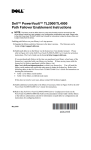
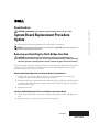
About Cautions
System Board Replacement Procedure
Update
This document provides updated information for replacing the system board.
NOTE: See the latest version of the system’s documentation on support.dell.com for instructions on how
to remove and replace the system board.
Removing and Installing the North Bridge Heat Sink
CAUTION: Any installation that requires removal of the system cover is intended solely to be
performed by trained service technicians. See your Product Information Guide for complete information
about safety precautions, working inside the computer and protecting against electrostatic discharge.
When transferring components from the defective system board to the replacement system board,
ensure that you also transfer the north bridge heat sink. The north bridge heat sink is located
directly behind processor connectors 2 and 4.
Removing the North Bridge Heat Sink From the Defective System Board
1 Compress the two retention-clip tabs together to remove them from the retention-clip
securing slots, and then lift up the retention clip. See Figure 1.
2 If the heat sink has not separated from the north bridge chip, carefully rotate the heat sink in
a clockwise, then counterclockwise, direction until it releases from the chip. Do not pry the
heat sink off of the chip.
3 Lift off the heat sink.
Installing the North Bridge Heat Sink on the Replacement System Board
1 Using a clean lint-free cloth, remove the existing thermal grease from the north bridge heat
sink.
2 Apply thermal grease evenly to the top of the north bridge chip.
March 2005
www.dell.com | support.dell.com
CAUTION: A CAUTION indicates a potential for property damage, personal injury, or death.
www.dell.com | support.dell.com
3 Install the north bridge heat sink:
a
Orient the heat sink so that its alignment key is toward the back of the system board. See
Figure 1.
b
Slowly lower the end of the heat sink closest to processor connectors 2 and 4 into the
heat-sink bracket.
c
After the heat sink contacts the bottom of the heat-sink bracket, align the keys on the
heat sink and the heat-sink bracket, then lower the heat sink until it lays flat in the
bracket. See Figure 1.
d
Lower the retention clip, compress the two retention-clip tabs together, and secure the
tabs into the retention-clip securing slots.
Figure 1. Removing and Installing the North Bridge Heat Sink
heat-sink alignment key
heat-sink bracket alignment key
retention-clip
tabs (2)
north bridge heat sink
heat-sink bracket
retention-clip
securing slots (2)
____________________
Information in this document is subject to change without notice.
© 2005 Dell Inc. All rights reserved. Printed in the U.S.A.
Reproduction in any manner whatsoever without the written permission of Dell Inc. is strictly forbidden.
Trademarks used in this text: Dell and the DELL logo are trademarks of Dell Inc.
Other trademarks and trade names may be used in this document to refer to either the entities claiming the marks and names
or their products. Dell Inc. disclaims any proprietary interest in trademarks and trade names other than its own.