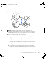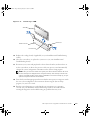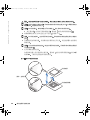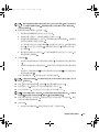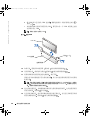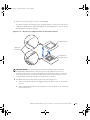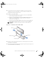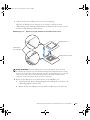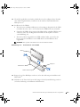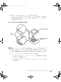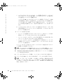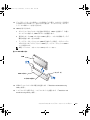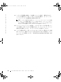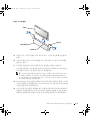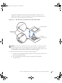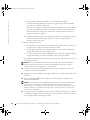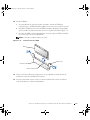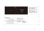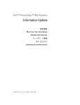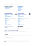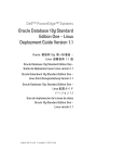
1
9D904et4.fm Page 1 Tuesday, October 1, 2002 11:56 PM
Dell™ Systems
Microprocessor Upgrade
Installation Guide
w w w. d e l l . c o m | s u p p o r t . d e l l . c o m
9D904et4.fm Page 2 Tuesday, October 1, 2002 11:56 PM
Notes, Notices, and Cautions
NOTE: A NOTE indicates important information that helps you make better use of your computer.
NOTICE: A NOTICE indicates either potential damage to hardware or loss of data and tells you
how to avoid the problem.
CAUTION: A CAUTION indicates a potential for property damage, personal injury,
or death.
Information in this document is subject to change without notice.
© 2002 Dell Computer Corporation. All rights reserved.
Reproduction in any manner whatsoever without the written permission of Dell Computer Corporation is strictly forbidden.
Trademarks used in this text: Dell and the DELL logo are trademarks of Dell Computer Corporation.
Other trademarks and trade names may be used in this document to refer to either the entities claiming the marks and
names or their products. Dell Computer Corporation disclaims any proprietary interest in trademarks and trade names
other than its own.
October 2002
P/N 9D904
Rev. A04
9D904eb4.fm Page 1 Tuesday, October 1, 2002 11:55 PM
This document provides instructions about adding or replacing microprocessors. To take
advantage of future options in speed and functionality, you can add secondary
microprocessors or replace microprocessors in your system.
NOTICE: Before you add or replace a microprocessor, check the latest system BIOS
information on the Dell Support website at support.dell.com, and upgrade the BIOS if necessary.
Each microprocessor and its associated cache memory are contained in a pin-grid array
(PGA) package that is installed in a ZIF socket on the system board. The following
subsection describes how to install or replace the microprocessor in either the primary or
secondary microprocessor sockets.
NOTE: In a single microprocessor system, the microprocessor must be installed in the
primary microprocessor socket.
Adding or Replacing a Microprocessor
NOTICE: The secondary microprocessors must be of the same type and speed as the primary
microprocessor. If the microprocessors are different speeds, they will operate at the speed of the
slower microprocessor.
In addition to the ZIF socket for the primary microprocessor on the system board, other
ZIF sockets might be present to accommodate secondary microprocessors.
The following items are included in the microprocessor upgrade kit:
•
A microprocessor
•
A heat sink
•
Heat-sink retention clip(s)
•
A VRM, used if adding a secondary microprocessor
Your upgrade kit may also include a cooling fan.
CAUTION: Before you perform this procedure, read the safety instructions in
your System Information document.
1
Turn off the system, including any peripherals, and disconnect the power cable from
the electrical outlet.
2
Open the system doors, or remove the system cover (see your Installation and
Troubleshooting Guide).
CAUTION: See "Protecting Against Electrostatic Discharge" in the safety
instructions in the System Information document.
M i c r o p r o c e s s o r U p g r a d e Installation Guide
1-1
w w w. d e l l . c o m | s u p p o r t . d e l l . c o m
9D904eb4.fm Page 2 Tuesday, October 1, 2002 11:55 PM
3
Remove the cooling shroud, if applicable (see your Installation and Troubleshooting
Guide).
4
If you are upgrading an existing microprocessor, remove the microprocessor heat sink.
NOTE: If a cooling fan is mounted on the heat sink, you can remove the heat sink without
removing the fan. However, you can remove the fan to provide easier access to the heat-sink
retention clip(s). For information on removing a cooling fan, see your Installation and
Troubleshooting Guide.
a
Remove the retention clip(s) securing the heat sink to the microprocessor by
pressing down firmly on the retention clip tab, and then removing the clip from
the heat sink.
See your system information label on the system cover for heat-sink retention clip
information.
CAUTION: The microprocessor and heat sink can become extremely hot. Be sure
they have had sufficient time to cool before handling.
NOTICE: Never remove the heat sink from a microprocessor unless you intend to remove the
microprocessor. The heat sink is necessary to maintain proper thermal conditions.
NOTICE: After removing the heat sink, place it upside down on a flat surface to prevent the
thermal interface material from being damaged or contaminated.
b
5
Remove the heat sink. See your Installation and Troubleshooting Guide for
information on removing the heat sink.
Swing the socket release lever upward to the fully open position (see Figure 1-1).
NOTICE: Be careful not to bend any of the pins when removing the microprocessor. Bending
the pins can permanently damage the microprocessor.
6
Lift the microprocessor out of the socket and leave the release lever in the open
position so that the socket is ready for the new microprocessor.
NOTICE: Be careful not to bend any of the pins when unpacking the microprocessor. Bending
the pins can permanently damage the microprocessor.
7
Unpack the new microprocessor.
If any of the pins on the microprocessor appear bent, see "Getting Help" in your
Installation and Troubleshooting Guide for instructions about obtaining technical
assistance.
1-2
Microprocessor Upgrade Installation Guide
9D904eb4.fm Page 3 Tuesday, October 1, 2002 11:55 PM
Figure 1-1.
Removing and Replacing the Microprocessor
microprocessor
pin-1 locators
microprocessor socket
NOTICE: Positioning the microprocessor incorrectly can permanently damage the
microprocessor and the system when you turn on the system. When placing the microprocessor
in the ZIF socket, be sure that all of the pins on the microprocessor go into the corresponding
holes. Be careful not to bend the pins.
8
Install the microprocessor in the socket (see Figure 1-1).
a
Ensure that the microprocessor socket release lever is in the fully open position.
b
Align pin 1 on the microprocessor with pin 1 on the microprocessor socket.
c
With pin 1 of the microprocessor and socket aligned, set the microprocessor
lightly in the socket and ensure that all pins are matched with the correct holes in
the socket.
Because the system uses a ZIF microprocessor socket, there is no need to use force
(which could bend the pins if the microprocessor is misaligned). When the
microprocessor is positioned correctly, it should drop down into the socket with
minimal pressure.
d
When the microprocessor is fully seated in the socket, rotate the socket release
lever back down until it snaps into place, locking the microprocessor in the socket.
M i c r o p r o c e s s o r U p g r a d e Installation Guide
1-3
9D904eb4.fm Page 4 Tuesday, October 1, 2002 11:55 PM
w w w. d e l l . c o m | s u p p o r t . d e l l . c o m
9
Install the heat sink.
•
If the heat sink provided has a foil thermal interface material strip on the bottom
of the heat sink, place the heat sink on the microprocessor.
•
If the heat sink provided has a thermal grease tab, remove the tab and place the
heat sink on the microprocessor.
•
If heat-sink thermal grease is provided, clean the heat sink and apply the thermal
grease before placing the heat sink on the microprocessor.
See your system information label on the system cover for the correct heat sink
orientation.
NOTICE: To avoid possible damage to the microprocessor, you must align the heat sink so that
the triangular mark on the heat sink points toward the triangular mark on the system board, if
applicable.
10
Orient the heat-sink retention clip as shown in your Installation and Troubleshooting
Guide.
11
Hook the end of the clip without the release tab over the tab on the edge of the socket.
12
Press down on the release tab until the hole on the clip latches onto the ZIF socket
tab.
NOTICE: If a cooling fan is provided with your upgrade kit, you must install the fan on the
microprocessor heat sink to provide proper thermal conditions. For information on installing a
cooling fan, see your Installation and Troubleshooting Guide.
13
If a cooling fan is provided with your upgrade kit or if you removed a cooling fan earlier
in this procedure, install the fan on the microprocessor heat sink.
14
Install the VRM(s):
a
If you are adding a secondary microprocessor, examine the VRM to ensure that it
is the correct VRM for your system.
b
Insert the VRM in the appropriate secondary VRM connector, ensuring that the
latches at each end of the connector engage (see Figure 1-2).
c
If you received two VRMs with the upgrade kit, replace the primary VRM already
installed in the system with one of the VRMs from the upgrade kit.
NOTE: The system does not support mismatched VRMs.
1-4
Microprocessor Upgrade Installation Guide
9D904eb4.fm Page 5 Tuesday, October 1, 2002 11:55 PM
Figure 1-2.
Installing a VRM
VRM
latches (2)
VRM connector
connector key
15
Replace the cooling shroud, if applicable (see your Installation and Troubleshooting
Guide).
16
Close the system doors, or replace the system cover (see your Installation and
Troubleshooting Guide).
17
Reconnect your system and peripherals to their electrical outlets, and turn them on.
As the system boots, it detects the presence of the new processor and automatically
changes the system configuration information in the System Setup program.
NOTE: After you access the inside of the system, the chassis intrusion detector will cause
an alert message to be displayed at the next system startup. This message is stored in the
system’s nonvolatile random-access memory (NVRAM). To clear this message log, see your
systems management software documentation.
18
Enter the System Setup program and ensure that the microprocessor categories match
the new system configuration. For instructions about using the System Setup
program, see your User’s Guide.
19
Run the system diagnostics to verify that the new microprocessor is operating
correctly. See your Installation and Troubleshooting Guide for information about
running the diagnostics and troubleshooting any problems that may occur.
M i c r o p r o c e s s o r U p g r a d e Installation Guide
1-5
w w w. d e l l . c o m | s u p p o r t . d e l l . c o m
9D904eb4.fm Page 6 Tuesday, October 1, 2002 11:55 PM
1-6
Microprocessor Upgrade Installation Guide
9D904ct4.fm Page 1 Tuesday, October 1, 2002
11:38 PM
Dell™ 系统
微处理器升级安装指南
w w w. d e l l . c o m | s u p p o r t . d e l l . c o m
9D904ct4.fm Page 2 Tuesday, October 1, 2002
11:38 PM
注 注意和警告
注 注表示可以帮助您更好地使用计算机的重要信息
注意 注意表示可能会损坏硬件或导致数据丢失 并告诉您如何避免此类问题
警告
警告表示可能会造成财产损失
本文件中的信息如有更改 恕不另行通知
© 2002 Dell Computer Corporation 版权所有
未经 Dell Computer Corporation 书面许可
本文件中使用的商标
人身伤害或死亡
翻印必究
不准以任何形式进行复制
Dell 和 DELL 徽标是 Dell Computer Corporation 的商标
本文件中述及的其它商标和产品名称是指拥有相应商标和产品名称的公司或其制造的产品
Corporation 对其它公司的商标和产品名称不拥有任何专利权
2002 年 10 月
P/N 9D904 Rev. A04
Dell Computer
9D904cb4.fm Page 1 Tuesday, October 1, 2002
11:37 PM
本说明文件提供了有关添加或更换微处理器的说明 您可以在系统中添加次微处理器
或更换微处理器 从而充分利用未来选件的速度和功能
注意
添加或更换微处理器之前 请先在 Dell 支持 Web 站点 support.dell.com 中查看最新
的系统 BIOS 信息 然后在必要时升级 BIOS
每个微处理器及其相应的高速缓存均包含在一个针型栅格阵列 (PGA) 包装内 此包装
安装在主机板上的 ZIF 插槽中 以下小节介绍了如何在微处理器主插槽或次插槽中安
装或更换微处理器
注
在配置单个微处理器的系统中
微处理器必须安装在主插槽中
添加或更换微处理器
注意
次微处理器的类型和速率必须与主微处理器相同
以较慢微处理器的速率来操作
除了主机板上用于主微处理器的 ZIF 插槽外
理器
如果微处理器的速率不同
则会
可能还有其它 ZIF 插槽用于安装次微处
微处理器升级套件包含以下内容
•
一个微处理器
•
一个散热器
•
散热器固定夹
•
添加次微处理器时需要使用的 VRM
升级套件中可能还包含一个冷却风扇
警告
执行此过程之前 请阅读 系统信息 说明文件中的安全说明
1
关闭系统
2
打开系统护盖
警告
包括任何外围设备
并从电源插座中断开电源电缆的连接
或者卸下主机盖
请参阅
安装与故障排除指南
请参阅 系统信息 文件安全说明部分中的 防止静电损害
3
如果可以
请卸下冷却通风罩
4
如果您升级现有的微处理器
请参阅
安装与故障排除指南
请卸下微处理器散热器
注 如果散热器上已安装冷却风扇 您无需卸下风扇即可卸下散热器 但是 卸下风
扇可以使您更方便地拆装散热器固定夹 有关卸下冷却风扇的信息 请参阅 安装与
故障排除指南
a
稳定地按下固定夹卡舌并从散热器上卸下此夹
器的固定夹
有关散热器固定夹的信息
卸下将散热器固定至微处理
请参阅主机盖上的系统信息标签
微处理器升级安装指南
2-1
9D904cb4.fm Page 2 Tuesday, October 1, 2002
w w w. d e l l . c o m | s u p p o r t . d e l l . c o m
警告
11:37 PM
微处理器和散热器可能会变得很热 请在处理之前确保它们有足够的时间冷却
注意
除非您准备卸下微处理器
的散热条件 则散热器必不可少
注意
b
5
卸下散热器
请将其倒置在平坦的表面上
有关卸下散热器的信息
将插槽释放拉杆向上转动至完全打开位置
注意
损坏
6
卸下散热器后
卸下微处理器时
从插槽中提出微处理器
微处理器
注意
如果要保持良好
防止损坏或玷污散热材料
请参阅
安装与故障排除指南
参见图 2-1
注意不要弄弯任何插针
弄弯插针将对微处理器造成无法修复的
并使释放拉杆保留在打开位置
在打开微处理器的包装时
无法修复的损坏
7
否则请勿将散热器从微处理器上卸下
请注意不要弄弯任何插针
以便在插槽中安装新的
弄弯插针将对微处理器造成
打开新微处理器的包装
如果微处理器上的任何插针出现弯曲 请参阅
了解有关获得技术帮助的说明
得帮助
图 2-1
安装与故障排除指南
卸下和更换微处理器
微处理器
插针 1 定位器
微处理器插槽
2-2
微处理器升级安装指南
中的
获
9D904cb4.fm Page 3 Tuesday, October 1, 2002
11:37 PM
注意
错误的放置微处理器将对微处理器和系统 如果您启动系统 造成无法修复的损
坏 在 ZIF 插槽中放置微处理器时 请确保微处理器上的所有插针均已插入相应的插孔
注意不要弄弯插针
8
将微处理器安装在插槽中
参见图 2-1
a
确保微处理器插槽释放拉杆处于完全打开位置
b
将微处理器上的插针 1 与微处理器插槽上的插针 1 对齐
c
将微处理器与插槽的插针 1 对齐后 请将微处理器轻轻放在插槽中 并确保所
有插针均与插槽中的插孔正确对齐
由于系统使用的是 ZIF 微处理器插槽 因此插入时无需用力 如果微处理器
未对齐 用力过度会弄弯插针
微处理器正确定位后 略微按压即可向下
进入插槽中
d
9
微处理器在插槽中完全就位后
微处理器锁定在插槽中
向下转回插槽释放拉杆直至其卡入到位
将
安装散热器
•
如果附带的散热器底部具有散热材料金属薄片
上
•
如果附带的散热器具有散热膏标签
上
•
如果附带了散热器散热膏
放置在微处理器上
有关正确的散热器方向
请将散热器放置在微处理器
请揭开标签并将散热器放置在微处理器
请先清洁散热器并涂抹散热膏
然后再将散热器
请参阅主机盖上的系统信息标签
注意
形标记
为避免损坏微处理器
如果可以
10
按照
安装与故障排除指南
11
挂住固定夹一端
12
向下按压释放卡舌
对齐散热器时应使其上面的三角形标记指向主机板上的三角
中的说明
确定散热器固定夹的方向
使释放卡舌不会挡在插槽边缘卡舌的上方
直至固定夹上的小孔锁定在 ZIF 插槽卡舌上
注意
如果升级套件附带了冷却风扇 则必须将风扇安装在微处理器散热器上
正确散热 有关安装冷却风扇的信息 请参阅 安装与故障排除指南
13
如果升级套件附带了冷却风扇
风扇安装在微处理器散热器上
14
安装 VRM
a
如果您添加次微处理器
从而确保
或者您在本过程早些时候卸下了冷却风扇
请将
请检查系统是否使用了正确的 VRM
微处理器升级安装指南
2-3
w w w. d e l l . c o m | s u p p o r t . d e l l . c o m
9D904cb4.fm Page 4 Tuesday, October 1, 2002
11:37 PM
b
将 VRM 插入适当的次 VRM 连接器
见图 2-2
c
如果您收到两个附带升级套件的 VRM
在系统中的主 VRM
注
图 2-2
确保连接器每一端的闩锁均已啮合
参
请用其中的一个 VRM 来替换已安装
系统不支持不匹配的 VRM
安装 VRM
VRM
闩锁
VRM 连接器
2个
连接器栓锁
15
如果可以
请装回冷却通风罩
16
关闭系统护盖
17
将系统和外围设备重新连接至电源插座
或者装回主机盖
请参阅
安装与故障排除指南
请参阅
安装与故障排除指南
然后开机
系统在引导时将检测是否存在新的处理器
配置信息
并且自动更改系统设置程序中的系统
注 拆装系统内部组件之后 机箱防盗检测器会使系统在下一次启动时显示一则警告
信息 此信息存储在系统的非易失性随机存取存储器 (NVRAM) 中 要清除此信息记
录 请参阅系统管理软件说明文件
2-4
18
进入系统设置程序 并确保微处理器类型与新的系统配置相符
置程序的说明 请参阅 用户指南
19
运行系统诊断程序 验证新的微处理器是否能正确运行
除任何故障的信息 请参阅 安装与故障排除指南
微处理器升级安装指南
有关使用系统设
有关运行诊断程序和排
9D904ft4.fm Page 1 Tuesday, October 1, 2002 10:59 PM
Systèmes Dell™
Guide d'installation pour la mise
à niveau du microprocesseur
w w w. d e l l . c o m | s u p p o r t . d e l l . c o m
9D904ft4.fm Page 2 Tuesday, October 1, 2002 10:59 PM
Remarques, mises en garde et avertissements
REMARQUE : UNE REMARQUE indique une information importante destinée à vous aider à
mieux utiliser votre ordinateur.
MISE EN GARDE : UNE MISE EN GARDE indique un dommage potentiel pouvant survenir
(ou une perte de données) et vous dit comment éviter le problème.
ATTENTION : Le message ATTENTION indique une situation potentiellement
dangereuse qui, si elle n'est pas évitée, peut provoquer une blessure mineure ou
modérée.
Les informations fournies dans ce document sont susceptibles d'être modifiées sans préavis.
© 2002 Dell Computer Corporation. Tous droits réservés.
La reproduction de ce document de quelque manière que ce soit sans l'autorisation écrite de Dell Computer Corporation
est strictement interdite.
Marques déposées utilisées dans ce guide : Dell et le logo DELL sont des marques de Dell Computer Corporation.
Toutes les autres marques déposées et noms de marques utilisés dans ce document se rapportent aux sociétés propriétaires
des marques et des noms de ces produits. Dell Computer Corporation décline tout intérêt dans l'utilisation des marques
déposées et des noms de marques ne lui appartenant pas.
octobre 2002
Réf. 9D904 Rév. A04
9D904fb4.fm Page 1 Tuesday, October 1, 2002 10:35 PM
Ce document contient des instructions concernant l'ajout ou le remplacement de
microprocesseurs. Pour pouvoir tirer parti des futures options offrant une vitesse plus élevée
ou des fonctionnalités supplémentaires, vous pouvez ajouter des microprocesseurs
secondaires ou remplacer ceux qui sont déjà installés dans votre système.
MISE EN GARDE : Avant d'ajouter ou de remplacer un microprocesseur, consultez les
dernières informations sur le BIOS système sur le site Web de support de Dell,
support.dell.com, et mettez à niveau le BIOS si nécessaire.
Chaque microprocesseur et sa mémoire cache associée sont contenus dans un module PGA
(pin-grid array) qui est installé dans un connecteur ZIF sur la carte système. La sous-section
suivante explique comment installer ou remplacer le microprocesseur sur les connecteurs
pour microprocesseur principal ou secondaire.
REMARQUE : Dans un système à un seul microprocesseur, celui-ci doit être installé
dans le connecteur de microprocesseur principal.
Ajout ou remplacement d'un microprocesseur
MISE EN GARDE : Le type et la vitesse des microprocesseurs secondaires doivent
être identiques à ceux du microprocesseur principal. Si les vitesses des
microprocesseurs diffèrent, c'est la vitesse du microprocesseur le plus lent qui est
adoptée.
Outre le connecteur ZIF destiné au microprocesseur principal sur la carte système, il peut
exister d'autres connecteurs ZIF prévus pour accueillir des microprocesseurs secondaires.
Le kit de mise à niveau du microprocesseur contient les éléments suivants :
•
Un microprocesseur
•
Un dissipateur thermique
•
Languette(s) de fixation du dissipateur thermique
•
Un module VRM, qui est utilisé en cas d'ajout d'un microprocesseur secondaire
Votre kit de mise à niveau peut aussi comporter un ventilateur.
ATTENTION : Avant d'exécuter cette procédure, lisez les instructions de sécurité
du document Informations sur le système.
1
Mettez le système hors tension, y compris les périphériques, puis débranchez le cordon
d'alimentation du secteur.
2
Ouvrez les portes du système, ou retirez le capot du système (reportez-vous au Guide
d'installation et de dépannage).
ATTENTION : Reportez-vous à la section “Protection contre les décharges
électrostatiques” dans les instructions de sécurité du document Informations sur
le système.
Guide d'installation pour la mi s e à niv e au du m ic r opr oc e s s e ur
3-1
w w w. d e l l . c o m | s u p p o r t . d e l l . c o m
9D904fb4.fm Page 2 Tuesday, October 1, 2002 10:35 PM
3
Retirez le dissipateur de chaleur, le cas échéant (reportez-vous au Guide d'installation
et de dépannage).
4
Si vous mettez à niveau un microprocesseur déjà installé, retirez son dissipateur
thermique.
REMARQUE : Si un ventilateur est monté sur le dissipateur thermique, vous
pouvez le retirer sans enlever le ventilateur. Toutefois, vous pouvez retirer le
ventilateur pour accéder plus facilement aux languettes de fixation du dissipateur
thermique. Pour savoir comment retirer le ventilateur, reportez-vous au Guide
d'installation et de dépannage.
a
Retirez la ou les languettes de fixation assujettissant le dissipateur thermique au
microprocesseur en appuyant fermement sur la patte de la languette, puis en
retirant la languette du dissipateur thermique.
Consultez l'étiquette d'informations apposée sur le capot du système pour plus de
précisions sur la languette de fixation du dissipateur thermique.
ATTENTION : Le microprocesseur et le dissipateur thermique peuvent être
brûlants. Laissez-les se refroidir suffisamment avant de les manipuler.
MISE EN GARDE : Ne retirez jamais le dissipateur thermique d'un microprocesseur
si vous n'avez pas l'intention de retirer le microprocesseur lui-même. Le dissipateur
thermique est en effet indispensable pour maintenir les conditions de température
adéquates.
MISE EN GARDE : Après avoir retiré le dissipateur thermique, placez-le à l'envers
sur une surface plane afin d'empêcher toute détérioration ou contamination du
matériau de l'interface thermique.
b
5
Retirez le dissipateur thermique. Reportez-vous au Guide d'installation et de
dépannage pour savoir comment procéder.
Poussez à fond vers le haut la manette de dégagement du connecteur afin de la placer
en position ouverte (voir la Figure 3-1).
MISE EN GARDE : Veillez à ne pas tordre les broches lors du retrait du
microprocesseur. Vous risqueriez sinon d'endommager définitivement le
microprocesseur.
6
Extrayez le microprocesseur du connecteur et laissez la manette de dégagement en
position ouverte, de façon à ce que le connecteur soit prêt à accueillir le nouveau
microprocesseur.
MISE EN GARDE : Veillez à ne pas tordre les broches lorsque vous extrayez le
microprocesseur de son emballage. Vous risqueriez sinon d'endommager
définitivement le microprocesseur.
3-2
Guide d'installation pour la mise à niveau du processeur
9D904fb4.fm Page 3 Tuesday, October 1, 2002 10:35 PM
7
Sortez le nouveau microprocesseur de son emballage.
Si certaines broches du microprocesseur semblent tordues, reportez-vous à la section
“Obtention d'aide” dans le Guide d'installation et de dépannage pour savoir comment
demander une assistance technique.
Figure 3-1.
Retrait et remplacement du microprocesseur
microprocesseur
repères de
la broche 1
connecteur du
microprocesseur
MISE EN GARDE : Un mauvais positionnement du microprocesseur risquerait
d'endommager définitivement le microprocesseur et le système lorsque vous le
remettrez sous tension. Lors de l'installation du microprocesseur dans le connecteur
ZIF, vérifiez que toutes les broches du microprocesseur s'enfoncent dans les trous
correspondants. Faites très attention à ne pas tordre les broches.
8
Installez le microprocesseur dans le connecteur (voir la Figure 3-1).
a
Assurez-vous que la manette de dégagement du microprocesseur est en position
ouverte.
b
Faites correspondre la broche 1 du microprocesseur sur la broche 1 du connecteur
du microprocesseur.
Guide d'installation pour la mi s e à niv e au du m ic r opr oc e s s e ur
3-3
9D904fb4.fm Page 4 Tuesday, October 1, 2002 10:35 PM
w w w. d e l l . c o m | s u p p o r t . d e l l . c o m
c
Une fois les broches 1 du microprocesseur et du connecteur alignées, mettez
doucement en place le microprocesseur dans le connecteur et assurez-vous que
toutes les broches correspondent bien aux trous appropriés du connecteur.
Le connecteur ZIF vous évite de devoir forcer pour installer le microprocesseur
(ce qui risquerait de tordre les broches si le microprocesseur n'est pas bien aligné).
Une fois le microprocesseur correctement positionné, une pression très légère doit
suffire pour pouvoir l'enfoncer dans le connecteur.
d
9
Lorsque le microprocesseur est installé à fond dans le connecteur, faites pivoter et
abaissez la manette de dégagement du connecteur jusqu'à ce qu'elle s'enclenche,
verrouillant le microprocesseur dans le connecteur.
Installez le dissipateur thermique.
•
Si le dessous du dissipateur thermique est recouvert d'une feuille de protection
thermique en papier métallisé, placez le dissipateur thermique sur le
microprocesseur.
•
Si le dissipateur thermique est doté d'une patte recouverte de graisse de
protection thermique, retirez cette patte et placez le dissipateur thermique sur le
microprocesseur.
•
Si la graisse de protection thermique est fournie à part, nettoyez le dissipateur
thermique et appliquez-lui une couche de cette graisse avant de le placer sur le
microprocesseur.
Consultez l'étiquette d'informations apposée sur le capot du système pour savoir
comment orienter le dissipateur thermique.
MISE EN GARDE : Pour éviter d'endommager le microprocesseur, vous devez orienter
le dissipateur thermique de façon à ce que le repère triangulaire du dissipateur pointe
vers le repère triangulaire de la carte système, le cas échéant.
10
Orientez la languette de fixation du dissipateur thermique en procédant comme
indiqué dans le Guide d'installation et de dépannage.
11
Accrochez l'extrémité de la languette sans la patte de dégagement sur la patte située
sur le rebord du connecteur.
12
Appuyez sur la patte de dégagement jusqu'à ce que le trou de la languette s'enclenche
sur la patte du connecteur ZIF.
MISE EN GARDE : Si votre kit de mise à niveau comporte un ventilateur, vous devez
installer le ventilateur sur le dissipateur thermique du microprocesseur afin de
maintenir une température appropriée. Pour savoir comment installer le ventilateur,
reportez-vous au Guide d'installation et de dépannage.
3-4
Guide d'installation pour la mise à niveau du processeur
9D904fb4.fm Page 5 Tuesday, October 1, 2002 10:35 PM
13
Si votre kit de mise à niveau comporte un ventilateur ou si vous avez retiré un
ventilateur au cours de cette procédure, vous devez installer le ventilateur sur le
dissipateur thermique du microprocesseur..
14
Installez le ou les modules VRM :
a
Si vous ajoutez un microprocesseur secondaire, examinez le module VRM et
assurez-vous qu'il convient à votre système.
b
Introduisez le module VRM dans le connecteur VRM secondaire approprié, en
veillant à ce que les loquets placés à chaque extrémité du connecteur
s'enclenchent (voir la Figure 3-2).
c
Si vous avez reçu deux modules VRM avec le kit de mise à niveau, remplacez le
module VRM principal déjà installé sur le système avec l'un des VRM du kit.
REMARQUE : Le système ne prend pas en charge les modules VRM non
équivalents.
Figure 3-2.
Installation d'un module VRM
VRM
latches (2)
VRM connector
connector key
15
Remettez en place le dissipateur de chaleur, le cas échéant (reportez-vous au Guide
d'installation et de dépannage).
16
Fermez les portes du système, ou remettez en place le capot du système (reportez-vous
au Guide d'installation et de dépannage).
Guide d'installation pour la mi s e à niv e au du m ic r opr oc e s s e ur
3-5
9D904fb4.fm Page 6 Tuesday, October 1, 2002 10:35 PM
w w w. d e l l . c o m | s u p p o r t . d e l l . c o m
17
Rebranchez le système et les périphériques sur leurs prises électriques, puis remettezles sous tension.
Lors de l'initialisation, le système détecte la présence du nouveau processeur et
modifie automatiquement les informations de configuration du système dans le
programme System Setup.
REMARQUE : Après que vous avez accédé à l'intérieur du système, le détecteur
d'ouverture non autorisée du châssis provoque l'affichage d'un message d'alerte
lors du redémarrage suivant du système. Ce message est enregistré dans la
mémoire NVRAM du système. Pour savoir comment effacer ce message, consultez
la documentation du logiciel de gestion du système.
3-6
18
Accédez au programme de configuration du système (System Setup) et vérifiez que les
catégories du microprocesseur correspondent bien à la nouvelle configuration. Pour
plus d'informations sur le programme System Setup, reportez-vous au Guide de
l'utilisateur.
19
Exécutez les diagnostics du système pour vérifier que le nouveau microprocesseur
fonctionne correctement. Reportez-vous au Guide d'installation et de dépannage pour
plus d'informations sur l'exécution des diagnostics et du dépannage des problèmes
éventuels.
Guide d'installation pour la mise à niveau du processeur
9D904gt4.fm Page 1 Tuesday, October 1, 2002 10:57 PM
Dell™-Systeme
Installationsanleitung für
Mikroprozessor-Upgrades
w w w. d e l l . c o m | s u p p o r t . d e l l . c o m
9D904gt4.fm Page 2 Tuesday, October 1, 2002 10:57 PM
Hinweis, Bitte Beachten und Vorsicht
HINWEIS: Ein HINWEIS enthält wichtige Informationen, mit deren Hilfe Sie Ihren Computer
besser nutzen können.
BITTE BEACHTEN: BITTE BEACHTEN weist auf eine mögliche Beschädigung von Hardware
oder den Verlust von Daten hin und beschreibt, wie dieses Problem vermieden werden kann.
VORSICHT: VORSICHT weist darauf hin, dass Gefahr für einen Sachschaden,
Personenschaden oder Lebensgefahr besteht.
Die in diesem Dokument enthaltenen Informationen können ohne Vorankündigung geändert werden.
© 2002 Dell Computer Corporation. Alle Rechte vorbehalten.
Eine Reproduktion dieses Dokuments in jeglicher Form ist nur mit vorheriger schriftlicher Genehmigung der Dell Computer
Corporation erlaubt.
Die in diesem Text verwendeten Warenzeichen: Dell und das DELL-Logo sind Warenzeichen der Dell Computer
Corporation.
Andere in diesem Dokument möglicherweise verwendete Warenzeichen und Handelsbezeichnungen sind unter Umständen
Marken und Namen der entsprechenden Firmen oder ihrer Produkte. Die Dell Computer Corporation erhebt keinen
Anspruch auf Warenzeichen oder Handelsnamen mit Ausnahme ihrer eigenen.
Oktober 2002
P/N 9D904 Rev. A04
9D904gb4.fm Page 1 Tuesday, October 1, 2002 10:41 PM
Dieses Dokument enthält eine Anleitung für das Hinzufügen oder Ersetzen von
Mikroprozessoren. Um von zukünftigen Verbesserungen hinsichtlich der Geschwindigkeit
und neuer Optionen profitieren zu können, können Sie zusätzliche (sekundäre)
Mikroprozessoren installieren oder die installierten Prozessoren austauschen.
BITTE BEACHTEN: Bevor Sie einen Mikroprozessor hinzufügen oder austauschen,
überprüfen Sie die aktuellsten System-BIOS-Informationen auf der Dell SupportWebsite unter support.dell.com und aktualisieren Sie Ihr BIOS, falls erforderlich.
Jeder Mikroprozessor und der zugehörige Cache-Speicher sind in einem PGA-Paket (PinGrid Array) enthalten, das in einem ZIF-Sockel auf der Mikroprozessor-Platine installiert
ist. Im folgenden Unterabschnitt wird beschrieben, wie der Mikroprozessor im Sockel des
primären oder sekundären Mikroprozessors eingebaut oder ausgetauscht wird.
HINWEIS: In einem System mit nur einem Mikroprozessor muss der Prozessor im
primären Prozessorsockel installiert sein.
Hinzufügen oder Austauschen eines
Mikroprozessors
BITTE BEACHTEN: Die sekundären Mikroprozessoren müssen vom gleichen Typ sein
wie der primäre Mikroprozessor und die gleiche Taktfrequenz wie dieser haben. Wenn
die Mikroprozessoren unterschiedliche Taktfrequenzen haben, arbeiten sie alle mit der
Taktfrequenz des langsameren Prozessors.
Neben dem ZIF-Sockel für den primären Mikroprozessor befinden sich auf der
Systemplatine möglicherweise weitere ZIF-Sockel für sekundäre Mikroprozessoren.
Das Mikroprozessor-Upgrade-Kit enthält die folgenden Teile:
•
Einen Mikroprozessor
•
Ein Wärmeableitblech
•
Halteclip(s) für das Wärmeableitblech
•
Ein VRM, falls ein sekundärer Mikroprozessor hinzugefügt wird.
Eventuell enthält Ihr Upgrade-Kit außerdem einen Lüfter.
VORSICHT: Bevor Sie mit diesem Verfahren beginnen, lesen Sie zunächst die
Sicherheitshinweise im Dokument Systeminformation.
1
Schalten Sie das System und sämtliche Peripheriegeräte aus und trennen Sie das
Netzkabel von der Stromversorgung.
2
Öffnen sie die Türen des Systems oder entfernen Sie die Systemabdeckung (siehe
dazu Anleitung zur Installation und Fehlersuche).
Installationsanleitung fü r M i k r o p r o z e s s o r- U p g r a d e s
4-1
9D904gb4.fm Page 2 Tuesday, October 1, 2002 10:41 PM
w w w. d e l l . c o m | s u p p o r t . d e l l . c o m
VORSICHT: Siehe „Schutz vor elektrostatischer Entladung“ in den
Sicherheitshinweisen im Dokument Systeminformation.
3
Entfernen Sie ggf. den Kühlkörper (siehe dazu Anleitung zur Installation und
Fehlersuche).
4
Wenn Sie ein Mikroprozessor-Update durchführen, entfernen Sie das
Wärmeableitblech des Prozessors.
HINWEIS: Wenn über dem Wärmeableitblech ein Lüfter montiert ist, brauchen
Sie nur das Blech zu entfernen. Allerdings können Sie auch den Lüfter entfernen,
um den/die Halteclip(s) des Wärmelableitblechs einfacher zu erreichen. Nähere
Informationen zum Ausbau eines Lüfters siehe Anleitung zur Installation und
Fehlersuche.
a
Entfernen Sie die Halteclips, mit denen das Wärmeableitblech am Mikroprozessor befestigt ist, indem Sie fest auf die Lasche an den Clips drücken und sie
dann vom Ableitblech abnehmen.
Informationen zum Halteclip des Wärmeableitblechs finden Sie auf dem
Systeminformations-Etikett auf der Abdeckung des Systems.
VORSICHT: Mikroprozessor und Wärmeableitblech können sehr heiß werden.
Stellen Sie sicher, dass beide Komponenten ausreichend Zeit zum Abkühlen
haben, bevor Sie sie berühren.
BITTE BEACHTEN: Nehmen Sie das Wärmeableitblech nur dann von einem
Mikroprozessor ab, wenn Sie den Mikroprozessor entfernen möchten. Das
Wäremeableitblech ist für die Aufrechterhaltung der korrekten Temperaturbedingungen
erforderlich.
BITTE BEACHTEN: Wenn das Wärmeableitblech entfernt ist, legen Sie es umgedreht
auf einen ebenen Untergrund, damit das Thermoschnittstellen-Material nicht
beschädigt oder verschmutzt wird.
b
5
Nehmen Sie das Wärmeableitblech ab. Näheres zum Ausbau des Wärmeableitblechs finden Sie in der Anleitung zur Installation und Fehlersuche.
Drehen Sie den Entriegelungshebel des Sockels nach oben in die vollständig geöffnete
Position (siehe Abbildung 4-1).
BITTE BEACHTEN: Achten Sie sorgfältig darauf, keine Pins zu verbiegen, wenn Sie
den Mikroprozessor herausnehmen. Ein Verbiegen der Pins kann eine dauerhafte
Beschädigung des Mikroprozessors zur Folge haben.
6
Heben Sie den Mikroprozessor aus dem Sockel, und belassen Sie den Hebel in der
senkrechten Position, damit der neue Mikroprozessor in den Sockel eingepasst werden
kann.
BITTE BEACHTEN: Achten Sie sorgfältig darauf, keine Pins zu verbiegen, wenn Sie
den Mikroprozessor auspacken. Ein Verbiegen der Pins kann eine dauerhafte
Beschädigung des Mikroprozessors zur Folge haben.
4-2
Installationsanleitung für Mikropr ozessor-Upgr ades
9D904gb4.fm Page 3 Tuesday, October 1, 2002 10:41 PM
7
Nehmen Sie den neuen Mikroprozessor aus seiner Verpackung.
Falls Pins am Mikroprozessor verbogen zu sein scheinen, erfahren Sie unter
„Hilfestellung“ in der Anleitung zur Installation und Fehlersuche Ihres Systems, wie Sie
technische Unterstützung erhalten können.
Abbildung 4-1.
Entfernen und Einbauen des Mikroprozessors
Mikroprozessor
Abgleichmarkierungen Pin 1
Mikroprozessor-Sockel
BITTE BEACHTEN: Wird der Mikroprozessor falsch eingesetzt, kann dies beim
Einschalten des Systems eine dauerhafte Beschädigung des Mikroprozessors und des
Systems zur Folge haben. Stellen Sie beim Einsetzen des Mikroprozessors in den ZIFSockel sicher, dass alle Pins des Mikroprozessors in die entsprechenden Löcher
eingreifen. Achten Sie darauf, die Pins nicht zu verbiegen.
8
Bauen Sie den Mikroprozessor in den Sockel ein (siehe Abbildung 4-1).
a
Achten Sie darauf, dass der Entriegelungshebel des Mikroprozessor-Sockels in der
vollständig geöffneten Position steht.
b
Richten Sie Pin 1 am Mikroprozessor nach Pin 1 am Mikroprozessor-Sockel aus.
Installationsanleitung fü r M i k r o p r o z e s s o r- U p g r a d e s
4-3
9D904gb4.fm Page 4 Tuesday, October 1, 2002 10:41 PM
w w w. d e l l . c o m | s u p p o r t . d e l l . c o m
c
Wenn Pin 1 des Mikroprozessors nach dem Sockel ausgerichtet ist, setzen Sie den
Mikroprozessor vorsichtig in den Sockel ein und stellen Sie sicher, dass alle Pins in
die korrekten Löcher im Sockel eingreifen.
Da das System einen ZIF-Mikroprozessor-Sockel verwendet, muss keine Kraft
aufgewendet werden (wenn der Prozessor falsch ausgerichtet ist, könnten Sie
sonst die Pins verbiegen). Wenn der Mikroprozessor korrekt positioniert ist, sollte
er mit minimalem Druck in den Sockel eingepasst werden können.
d
9
Sitzt der Mikroprozessor ordnungsgemäß im Sockel, bewegen Sie den Hebel zum
Lösen des Sockels wieder nach unten, bis er einrastet. Hierdurch wird der
Mikroprozessor im Sockel verriegelt.
Bauen Sie das Wärmeableitblech ein.
•
Falls das Wärmeableitblech an der Unterseite mit einem Folienstreifen aus
Thermoschnittstellen-Material versehen ist, platzieren Sie das Ableitblech auf den
Mikroprozessor.
•
Falls das Ableitblech eine Thermofett-Lasche besitzt, nehmen Sie die Lasche ab
und setzen Sie das Blech auf den Mikroprozessor.
•
Falls Thermofett für das Wärmeableitblech mitgeliefert wurde, reinigen Sie das
Blech und tragen Sie das Thermofett auf, bevor Sie das Blech auf den
Mikroprozessor setzen.
Informationen zur korrekten Ausrichtung des Wärmeableitblechs finden Sie auf dem
Systeminformations-Etikett auf der Systemabdeckung.
BITTE BEACHTEN: Um eine mögliche Beschädigung des Mikroprozessors zu
vermeiden, muss der Lüfter so ausgerichtet werden, dass die dreieckige Markierung
am Lüfter auf die dreieckige Markierung auf der Systemplatine zeigt (falls
zutreffend).
10
Richten Sie den Halteclip des Wärmeableitblechs wie in der Anleitung zur Installation
und Fehlersuche gezeigt aus.
11
Haken Sie das Ende des Clips ohne Lasche in die Lasche am Rand des Sockels ein.
12
Drücken Sie auf die Entriegelungslasche, bis das Loch im Clip in die Lasche am ZIFSockel einrastet.
BITTE BEACHTEN: Wenn Ihr Upgrade-Kit einen Lüfter enthält, müssen Sie ihn auf
dem Wärmeableitblech des Mikroprozessors installieren, um ordnungsgemäße
Temperaturbedingungen zu erzeugen. Nähere Informationen zur Installation eines
Lüfters finden Sie in der Anleitung zur Installation und Fehlersuche.
4-4
Installationsanleitung für Mikropr ozessor-Upgr ades
9D904gb4.fm Page 5 Tuesday, October 1, 2002 10:41 PM
13
Wenn Ihr Upgrade-Kit einen Lüfter enthält oder wenn Sie zu Beginn dieser Prozedur
einen Lüfter ausgebaut haben, installieren Sie ihn auf dem Wärmeableitblech des
Mikroprozessors.
14
Installieren Sie die VRM(s)
a
Wenn Sie einen sekundären Mikroprozessor hinzufügen, überprüfen Sie das VRM
und stellen Sie sicher, dass es sich um das korrekte VRM für Ihr System handelt.
b
Setzen Sie das VRM in den geeigneten Steckplatz für das sekundäre VRM ein und
stellen Sie sicher, dass die Riegel an beiden Enden des Steckplatzes einrasten
(siehe Abbildung 4-2).
c
Wenn Sie in Ihrem Upgrade-Kit zwei VRMs erhalten haben, ersetzen Sie den
bereits im System installierten ersten VRM durch einen der VRMs aus dem
Upgrade-Kit.
HINWEIS: Das System unterstützt keine unterschiedlichen VRMs.
Abbildung 4-2.
Installation eines VRM
VRM
Riegel (2)
VRM-Stecker
Steckermarkierung
15
Bringen Sie ggf. den Kühlkörper wieder an (siehe dazu Anleitung zur Installation und
Fehlersuche).
16
Schließen sie die Türen des Systems oder bringen Sie die Systemabdeckung wieder an
(siehe dazu Anleitung zur Installation und Fehlersuche).
Installationsanleitung fü r M i k r o p r o z e s s o r- U p g r a d e s
4-5
9D904gb4.fm Page 6 Tuesday, October 1, 2002 10:41 PM
w w w. d e l l . c o m | s u p p o r t . d e l l . c o m
17
Verbinden Sie das System und die Peripheriegeräte wieder mit der Stromversorgung,
und schalten Sie das System und die Geräte ein.
Beim Booten erkennt das System den neuen Prozessor und ändert automatisch die
Systemkonfigurations-Daten im System-Setup-Programm.
HINWEIS: Wenn Sie an der Innenseite des Systems gearbeitet haben, bewirkt der
Chassis-Störungsdetektor, dass beim nächsten Hochfahren des Systems eine
Warnmeldung angezeigt wird. Diese Meldung wird im nicht flüchtigen
Arbeitsspeicher (NVRAM) des Systems gespeichert. Informationen über das
Verfahren zum Löschen dieses Meldungsprotokolls finden Sie in der
Dokumentation der Systemverwaltungs-Software.
4-6
18
Rufen Sie das Setup-Programm des Systems auf und stellen Sie sicher, dass die
Mikroprozessor-Kategorien mit der neuen Systemkonfiguration übereinstimmen.
Informationen über die Verwendung des System-Setup-Programms finden Sie in
Ihrem Benutzerhandbuch.
19
Führen Sie die Systemdiagnose aus, um sicherzustellen, dass der neue Mikroprozessor
korrekt arbeitet. Informationen zum Diagnoseprogramm und der Suche nach
eventuellen Fehlern finden Sie in der Anleitung zur Installation und Fehlersuche.
Installationsanleitung für Mikropr ozessor-Upgr ades
9D904jt4.fm Page 1 Tuesday, October 1, 2002
11:31 PM
Dell™ システム
マイクロプロセッサアップグレード
インストールガイド
w w w. d e l l . c o m / j p / | s u p p o r t . j p . d e l l . c o m
9D904jt4.fm Page 2 Tuesday, October 1, 2002
11:31 PM
メモ、注意および警告
メモ : メモは、コンピュータを使いやすくする為の重要な情報を説明しています。
注意 : 注意は、ハードウェアの損傷やデータの損失の可能性があることを示し、その危険
を回避するための方法を説明しています。
警告 : 警告は、物的損害、けが、または死亡の原因となる可能性があることを示します。
ここに記載されている内容は予告なく変更されることがあります。
© 2002 すべての著作権は Dell Computer Corporation にあります。
Dell Computer Corporation の書面による許可のない複写は、いかなる形態においても厳重に禁じられていま
す。
本書で使用されている商標について: Dell および DELL ロゴは Dell Computer Corporation の商標です。
本書では、必要に応じて上記記載以外の商標および会社名が使用されている場合がありますが、 これらの商
標や会社名は、一切 Dell Computer Corporation に所属するものではありません。
2002 年 10 月
P/N 9D904 Rev. A04
9D904jb4.fm Page 1 Wednesday, October 2, 2002 12:23 AM
本書には、マイクロプロセッサの追加または交換に関する情報が記載されています。
将来の動作速度や機能性の向上に対応できるように、システムにセカンドマイクロプ
ロセッサを追加したり、マイクロプロセッサを交換したりすることができます。
注意 : マイクロプロセッサを追加または交換する前に、Dell サポート Web サイト
support.dell.com でシステムに対応した BIOS 情報を確認し、必要に応じて BIOS をアッ
プグレードしてください。
各マイクロプロセッサとそれぞれのキャッシュメモリは、システムボードの ZIF ソ
ケットに取り付けられる PGA (pin-grid array) パッケージに封止されています。次の
各セクションでは、プライマリマイクロプロセッサソケットまたはセカンドマイク
ロプロセッサソケットのどちらかにマイクロプロセッサを取り付け、または交換す
る方法について説明します。
メモ : シングルマイクロプロセッサシステムの場合は、プライマリマイクロプロセッサ
ソケットにマイクロプロセッサを取り付ける必要があります。
マイクロプロセッサの追加または交換
注意 : セカンドマイクロプロセッサのタイプと動作速度は、プライマリマイクロプロ
セッサと同じにする必要があります。マイクロプロセッサの動作速度に違いがあると、
遅い方のマイクロプロセッサの速度で動作することになります。
システム基板には、プライマリマイクロプロセッサ用の ZIF ソケット以外に、セカ
ンドマイクロプロセッサ用の ZIF ソケットが搭載されていることもあります。
マイクロプロセッサアップグレードキットには、次の部品が入っています。
•
マイクロプロセッサ
•
ヒートシンク
•
ヒートシンク固定クリップ
•
セカンドマイクロプロセッサを追加する場合に使用する VRM
アップグレードキットには、冷却ファンが付属している場合もあります。
警告 : この手順を行う前に、『システム情報』マニュアルの安全上の注意を参照してく
ださい。
1
システムとすべての周辺機器の電源を切り、電源コードを電源コンセントから
抜きます。
2
システムのドアを開けるか、システムのカバーを取り外します(『Installation
and Troubleshooting Guide』参照)。
マイクロプロセッサアップグレードインストールガイド
5-1
9D904jb4.fm Page 2 Wednesday, October 2, 2002 12:23 AM
w w w. d e l l . c o m / j p / | s u p p o r t . j p . d e l l . c o m
警告 : 『システム情報』マニュアルにある安全上の注意の「静電気障害への対処」を参
照してください。
3
冷却エアフローカバーがある場合は取り外します(『Installation and Troubleshooting
Guide』参照)。
4
既存のマイクロプロセッサをアップグレードする場合は、マイクロプロセッサ
のヒートシンクを取り外します。
メモ : ヒートシンクに冷却ファンが装着されている場合は、ファンを装着したまま
でヒートシンクを取り外すことができます。ただし、ヒートシンクの固定クリップ
に届きやすくなるようにするため、冷却ファンを取り外してもかまいません。冷却
ファンの取り外し方法の詳細については、『Installation and Troubleshooting Guide』を
参照してください。
a
固定クリップタブをしっかり押し下げ、ヒートシンクをマイクロプロセッサ
に固定している固定クリップを外します。次に、ヒートシンクからクリップ
を取り外します。
ヒートシンクの固定クリップの詳細については、システムカバーに貼付さ
れているシステム情報ラベルを参照してください。
警告 : マイクロプロセッサとヒートシンクは高温になることがあります。十分な冷却時
間を置いてから手を触れてください。
注意 : マイクロプロセッサを取り外すとき以外は、マイクロプロセッサからヒートシン
クを取り外さないでください。ヒートシンクは適切な温度条件を保つために必要な部品
です。
注意 : 取り外したヒートシンクは、平面の上に裏返して置き、サーマルインタフェース
材の損傷や汚れを防止します。
b
5
ヒートシンクを取り外します。ヒートシンクの取り外し方法の詳細につい
ては、『Installation and Troubleshooting Guide』を参照してください。
ソケットリリースレバーを、完全に開放された状態の位置まで持ち上げます
(図 5- 1参照)。
注意 : ピンを曲げないように注意して、マイクロプロセッサを取り外してください。ピ
ンを曲げるとマイクロプロセッサが破損して修復できないことがあります。
6
ソケットからマイクロプロセッサを抜き取ります。リリースレバーは開放され
た状態のままにし、ソケットに新しいマイクロプロセッサをすぐに取り付けら
れるようにしておきます。
注意: マイクロプロセッサを取り外す際には、1 つでもピンを曲げないように注意してく
ださい。ピンを曲げるとマイクロプロセッサが破損して修復できないことがあります。
5-2
マイクロプロセッサアップグレードインストールガイド
9D904jb4.fm Page 3 Wednesday, October 2, 2002 12:23 AM
7
新しいマイクロプロセッサをパッケージから取り出します。
1 つでもマイクロプロセッサのピンが曲がってしまった場合は、『Installation
and Troubleshooting Guide』の「困ったときは」を参照して、テクニカルサポー
トにお問い合わせください。
図 5-1. マイクロプロセッサの取り外しと交換
マイクロプロセッサ
ピン 1
ロケータ
マイクロプロセッサ
ソケット
注意 : マイクロプロセッサの取り付け位置が間違っていると、システムに電源を入れた
ときにマイクロプロセッサとシステムが完全に損傷する可能性があります。マイクロプ
ロセッサを ZIF ソケットに差し込む場合は、マイクロプロセッサのすべてのピンを対応
するピン穴に確実に挿入してください。ピンを曲げないように十分注意してください。
8
ソケットにマイクロプロセッサを取り付けます(図 5-1 参照)。
a
マイクロプロセッサのソケットリリースレバーが、完全に開放された状態の
位置にあることを確認します。
b
マイクロプロセッサのピン 1 とマイクロプロセッサソケットのピン 1 の位置
を合わせます。
マイクロプロセッサアップグレードインストールガイド
5-3
w w w. d e l l . c o m / j p / | s u p p o r t . j p . d e l l . c o m
9D904jb4.fm Page 4 Wednesday, October 2, 2002 12:23 AM
c
マイクロプロセッサとソケットのピン 1 の位置を合わせたら、マイクロプ
ロセッサをソケットの上に軽く載せ、すべてのピンがソケットの対応する
穴の位置に合っていることを確認します。
システムでは ZIF マイクロプロセッサソケットを使用しているので、力を加
える必要はありません(力を加えると、マイクロプロセッサの位置が合っ
ていない場合にピンを曲げてしまう可能性があります)。マイクロプロ
セッサが所定の位置に合ったら、余分な力を加えずにソケットを押し下げ
ます。
d
9
マイクロプロセッサがソケットにしっかり据え付けられたら、パチンと音
が出る位置までソケットリリースレバーを押し戻し、マイクロプロセッサ
をソケットに固定します。
ヒートシンクを取り付けます。
•
ヒートシンクの底部にホイルサーマルインタフェース材ストリップがある
場合は、ヒートシンクをマイクロプロセッサの上に置きます。
•
ヒートシンクにサーマルグリースタブがある場合は、タブを取り除いてか
らヒートシンクをマイクロプロセッサの上に置きます。
•
ヒートシンクのサーマルグリースが用意されている場合は、ヒートシンク
を清掃してサーマルグリースを塗布してから、マイクロプロセッサの上に
ヒートシンクを置きます。
ヒートシンクの正しい向きについては、システムカバーに貼付されているシス
テム情報ラベルを参照してください。
注意 : マイクロプロセッサの損傷を防ぐため、ヒートシンクの向きを調整して、ヒート
シンクの三角形の印とシステム基板の三角形の印が向き合うようにする必要があります。
10
『Installation and Troubleshooting Guide』の指示に従って、ヒートシンクの固定ク
リップの向きを合わせます。
11
リリースタブのないクリップの端を、ソケットのエッジのタブに引っ掛けます。
12
クリップの穴が ZIF ソケットタブにはまるまで、リリースタブを押し下げます。
注意 : アップグレードキットに冷却ファンが付属している場合は、温度条件を適正に保
つために、マイクロプロセッサのヒートシンクに冷却ファンを取り付ける必要がありま
す。冷却ファンの取り付け方法の詳細については、『Installation and Troubleshooting
Guide』を参照してください。
5-4
マイクロプロセッサアップグレードインストールガイド
9D904jb4.fm Page 5 Wednesday, October 2, 2002 12:23 AM
13
アップグレードキットに冷却ファンが付属している場合、またはここで説明す
る手順のはじめに冷却ファンを取り外した場合は、マイクロプロセッサのヒー
トシンクに冷却ファンを取り付けます。
14
VRM を取り付けます。
a
セカンドマイクロプロセッサを追加する場合は、VRM を点検して、お使い
のシステムに対応した VRM であることを確認します。
b
適切なセカンド VRM コネクタに VRM を挿入し、コネクタ両端のラッチで
確実に固定します(図 5-2 参照)。
c
アップグレードキットに 2 つの VRM が含まれている場合、すでにシステム
に取り付けられているプライマリ VRM をアップグレードキットの VRM の
1 つと交換します。
メモ : システムは、一致していない VRM をサポートしません。
図 5-2. VRM の取り付け
VRM
VRM コネクタ
ラッチ(2)
コネクタの仕切り
15
冷却エアフローカバーがある場合は交換します(『Installation and Troubleshooting
Guide』参照)。
16
システムのドアを閉じるか、システムのカバーを交換します(『Installation and
Troubleshooting Guide』参照)。
マイクロプロセッサアップグレードインストールガイド
5-5
w w w. d e l l . c o m / j p / | s u p p o r t . j p . d e l l . c o m
9D904jb4.fm Page 6 Wednesday, October 2, 2002 12:23 AM
17
システムと周辺機器の電源コードを電源コンセントに接続し、電源を入れます。
システムが起動すると、新しいプロセッサの存在を検知し、セットアップユー
ティリティのシステム設定情報を自動的に変更します。
メモ : システムの内部に手を加えると、シャーシイントルージョンディテクタが働
き、次のシステム起動時に警告メッセージが表示されます。このメッセージはシス
テムの NVRAM(不揮発性 RAM)に保存されます。 このメッセージログをクリアす
るには、システム管理ソフトウェアのマニュアルを参照してください。
5-6
18
セットアップユーティリティを起動し、マイクロプロセッサの項目が新しいシ
ステム構成と一致していることを確認します。セットアップユーティリティの
使用方法の詳細については、『ユーザーズガイド』を参照してください。
19
システム診断を実行し、新しいマイクロプロセッサが正しく動作することを確
認してください。診断プログラムの実行方法および生じた問題のトラブル
シューティングの詳細については、『Installation and Troubleshooting Guide』を参
照してください。
マイクロプロセッサアップグレードインストールガイド
9D904kt4.fm Page 1 Tuesday, October 1, 2002 11:45 PM
Dell™ 시스템
마이크로프로세서 업그레이드
설치 안내서
w w w. d e l l . c o m | s u p p o r t . d e l l . c o m
9D904kt4.fm Page 2 Tuesday, October 1, 2002 11:45 PM
주 , 주의사항 및 주의
주 : 주는 컴퓨터를 보다 효율적으로 사용할 수 있도록 중요 정보를 제공합니다 .
주의사항 : 주의사항은 하드웨어의 손상 또는 데이타 유실 위험을 설명하며 ,
이러한 문제를 방지할 수 있는 방법을 알려줍니다 .
주의 : 주의는 발생가능한 손상 , 부상 또는 사망할 우려가 있음을 알려줍니다 .
본 설명서에 수록된 정보는 사전 통보없이 변경될 수 있습니다 .
© 2002 Dell Computer Corporation. 저작권 본사 소유 .
Dell Computer Corporation 의 서면 승인 없이 어떠한 방법으로도 무단 복제하는 것을 엄격히 금합니다 .
본 설명서에 사용된 상표 : Dell, DELL 로고는 Dell Computer Corporation 의 상표입니다 .
특정 회사의 표시나 회사명 또는 제품을 지칭하기 위해 다른 상표나 상호를 본 설명서에서 사용할 수도
있습니다 . Dell Computer Corporation 은 자사가 소유하고 있는 상표 이외의 다른 모든 등록 상표 및
상표명에 대해 어떠한 소유권도 없음을 알려 드립니다 .
2002 년 6 월
P/N 9D904 Rev. A04
9D904kb4.fm Page 1 Wednesday, October 2, 2002 12:26 AM
본 설명서에서는 마이크로프로세서를 추가하거나 교체하는 지침을 제공합니다 .
속도와 기능적인 옵션을 나중에 이용하기 위해 시스템에 보조 마이크로프로세서를
추가하거나 마이크로프로세서를 교체할 수 있습니다 .
주의사항 : 마이크로프로세서를 추가하거나 교체하기 전에 Dell 지원 웹사이트
(support.dell.com) 에서 최신 BIOS 정보를 확인하고 필요하면 BIOS 를 업그레이드하
십시오 .
각 마이크로프로세서와 연계된 캐쉬 메모리는 시스템 보드에 있는 ZIF 소켓에 설치된
PGA(Pin-Grid Array) 패키지에 포함되어 있습니다. 다음 부절에서는 주 또는 보조
마이크로프로세서 소켓 중 하나에 마이크로프로세서를 설치하거나 교체하는 방법을
설명합니다 .
주 : 단일 마이크로프로세서 시스템인 경우 , 마이크로프로세서는 반드시 주
마이크로프로세서 소켓에 설치해야 합니다 .
마이크로프로세서 추가 또는 교체
주의사항 : 보조 마이크로프로세서는 주 마이크로프로세서와 같은 유형과 속도를
사용해야 합니다 . 마이크로프로세서의 속도가 다를 경우 , 마이크로프로세서가
느린 속도로 작동됩니다 .
보조 마이크로프로세서를 장착하려면 시스템 보드에 있는 주 마이크로프로세서의
ZIF 소켓 뿐만 아니라 다른 ZIF 소켓도 필요합니다 .
다음 항목은 마이크로프로세서 업그레이트 키트에 포함되어 있는 내용물입니다 :
•
마이크로프로세서 1 개
•
방열판 1 개
•
방열판 고정 클립
•
VRM( 보조 마이크로프로세서를 추가하여 사용하는 경우 )
업그레이드 키트에는 냉각팬이 포함되어 있을 수도 있습니다 .
주의 : 이 과정을 수행하기 전에 ≪시스템 정보 설명서≫에 있는 안전 지침 사항을
읽어보십시오 .
1
시스템과 모든 주변장치의 전원을 끄고 전원 콘센트에서 전원 케이블을
분리하십시오 .
2
시스템 도어를 열거나 시스템 덮개를 분리하십시오 ( ≪설치 및 문제 해결
설명서≫ 참조 ).
마이크로프로세서 업그레이드 설치 안내서
6-1
9D904kb4.fm Page 2 Wednesday, October 2, 2002 12:26 AM
w w w. d e l l . c o m | s u p p o r t . d e l l . c o m
주의 : ≪시스템 정보 설명서≫의 안전 지침에 있는 「정전기 방전 방지」를
참조하십시오 .
3
가능한 경우 , 냉각기 덮개를 분리하십시오 ( ≪설치 및 문제 해결 설명서≫ 참조 ).
4
기존의 마이크로프로세서를 업그레이드하는 경우에는 마이크로프로세서
방열판을 분리하십시오 .
주 : 냉각팬이 방열판에 장착되어 있는 경우 , 팬을 분리하지 않고도 방열판을 분리할
수 있습니다 . 그러나 팬을 분리하면 방열판 고정 클립에 좀 더 손쉽게 액세스할 수
있습니다 . 냉각팬을 분리하는 내용은 ≪설치 및 문제 해결 설명서≫를 참조하십시오 .
a
고정 클립 탭을 세게 눌러 마이크로프로세서에 방열판을 고정시켜 주는 고정
클립을 분리한 다음 방열판에서 클립을 분리하십시오 .
방열판 고정 클립에 대한 정보는 시스템 덮개에 있는 시스템 정보 레이블을
참조하십시오 .
주의 : 마이크로프로세서와 방열판의 온도가 올라가 매우 뜨거워질 수 있습니다 .
마이크로프로세서를 만지기 전에 충분한 시간을 두어 열을 식히십시오 .
주의사항 : 마이크로프로세서를 분리하지 않을 경우 , 마이크로프로세서에서 방열판을
절대로 분리하십시오 . 방열판은 온도를 알맞게 유지하는데 필요합니다 .
주의사항 : 방열판을 분리한 후에 표면이 손상되거나 오염되지 않도록 평평한 곳에
뒤집어 놓아야 합니다 .
b
5
방열판을 분리하십시오 . 방열판을 분리하는 내용은 ≪설치 및 문제 해결
설명서≫를 참조하십시오 .
소켓 분리 레버를 위로 돌려 완전히 젖혀지도록 하십시오 ( 그림 6-1 참조 ).
주의사항 : 마이크로프로세서를 분리할 때 , 핀이 구부러지지 않도록 주의하십시오 .
핀이 구부러지면 마이크로프로세서가 영구적으로 손상될 수 있습니다 .
6
마이크로프로세서를 소켓에서 들어 올리고 분리 레버를 열림 위치에 놓으면
소켓에 새로운 마이크로프로세서를 설치할 준비가 됩니다 .
주의사항 : 마이크로프로세서의 포장을 풀 때 핀이 구부러지지 않도록 주의하십시오 .
핀이 구부러지면 마이크로프로세서가 영구적으로 손상될 수 있습니다 .
7
새 마이크로프로세서의 포장을 푸십시오 .
마이크로프로세서의 핀이 구부러진 경우에 기술 지원을 받으려면 ≪설치 및
문제 해결 설명서≫의 「도움말 얻기」를 참조하십시오 .
6-2
마이크로프로세서 업그레이드 설치 안내서
9D904kb4.fm Page 3 Wednesday, October 2, 2002 12:26 AM
그림 6-1. 마이크로프로세서 분리 및 교체
마이크로프로세서
1번 핀
위치 지정자
마이크로프로세서 소켓
주의사항 : 마이크로프로세서를 부정확한 위치에 넣으면 시스템의 전원을 켤 때
마이크로프로세서와 시스템이 영구적으로 손상될 수 있습니다 . ZIF 소켓에
마이크로프로세서를 끼워 넣을 때 , 마이크로프로세서의 모든 핀이 해당 구멍에
올바르게 놓여 있는지 확인하십시오 . 또한 , 핀이 구부러지지 않도록 주의하십시오 .
8
소켓에 마이크로프로세서를 설치하십시오 ( 그림 6-1 참조 ).
a
마이크로프로세서 소켓 분리 레버가 완전히 젖혀졌는지 확인하십시오 .
b
마이크로프로세서의 1 번 핀과 마이크로프로세서 소켓에 있는 1 번 핀을
맞추십시오 .
c
마이크로프로세서의 1 번 핀과 소켓을 맞추면 마이크로프로세서를 소켓에
살짝 놓아도 제자리에 끼워집니다 . 모든 핀이 소켓의 구멍과 올바르게
일치하는지 확인하십시오 .
시스템은 ZIF 마이크로프로세서 소켓을 사용하므로 세게 힘을 가할 필요가
없습니다 . 세게 힘을 주면 마이크로프로세서를 잘못 끼웠을 때 핀이
구부러질 수 있습니다 . 마이크로프로세서를 올바르게 정렬하고 ,
마이크로프로세서를 살짝 누르면 소켓에 정확하게 끼워집니다 .
d
마이크로프로세서를 소켓에 완전히 끼울때 , 소켓에 마이크로프로세서를
고정시켜 주는 소켓 분리 레버가 제자리에 걸릴 때까지 아래쪽으로
돌리십시오 .
마이크로프로세서 업그레이드 설치 안내서
6-3
9D904kb4.fm Page 4 Wednesday, October 2, 2002 12:26 AM
w w w. d e l l . c o m | s u p p o r t . d e l l . c o m
9
방열판을 설치하십시오 .
•
제공된 방열판 밑면에 박막 열선이 있는 경우 , 방열판을 마이크로프로세서
위에 놓으십시오 .
•
제공된 방열판에 열 그리즈 탭이 있는 경우 , 탭을 제거하고 방열판을
마이크로프로세서 위에 놓으십시오 .
•
방열판 열 그리즈가 제공된 경우 , 마이크로프로세서 위에 방열판을 놓기
전에 방열판을 깨끗이 닦고 열 그리즈를 사용하십시오 .
방열판의 올바른 위치는 시스템 덮개에 있는 시스템 정보 레이블을
참조하십시오 .
주의사항 : 마이크로프로세서의 손상을 방지하려면 , 방열판에 있는 삼각형 표시가 시스템
보드에 있는 삼각형 표시 쪽을 가리키도록 방열판을 맞추어야 합니다 ( 가능한 경우 ).
10
≪설치 및 문제 해결 설명서≫에 표시된 그림과 같이 방열판 고정 클립을
놓으십시오 .
11
소켓 모서리에 있는 탭 위에 분리 탭이 아닌 클립 끝부분에 걸리도록 놓으십시오 .
12
ZIF 소켓 탭에 클립 구멍이 걸릴 때까지 분리 탭을 아래로 누르십시오 .
주의사항 : 업그레이드 키트에 냉각팬이 제공된 경우 , 온도를 적절히 유지시키기 위해
팬을 마이크로프로세서 방열판에 설치해야 합니다 . 냉각팬을 설치하는 방법은 ≪설치 및
문제 해결 설명서≫를 참조하십시오 .
13
냉각팬이 업그레이드 키트와 함께 제공되었거나 이전 과정에서 냉각팬을
분리했던 경우에는 팬을 마이크로프로세서 방열판에 설치하십시오 .
14
VRM 을 설치하십시오 :
a
보조 마이크로프로세서를 추가하려면 시스템에 맞는 VRM 인지 확인하십시
오.
b
커넥터 각 끝부분의 래치가 맞물리는지 확인하면서 해당 보조 VRM 커넥터
에 VRM 을 넣으십시오 ( 그림 6-2 참조 ).
c
업그레이드 키트에 2 개의 VRM 이 포함되어 있는 경우에는 그 중 한 개를 골
라 시스템에 설치되어 있는 주 VRM 과 교체하십시오 .
주 : 시스템은 맞지 않는 VRM 을 지원하지 않습니다 .
6-4
마이크로프로세서 업그레이드 설치 안내서
9D904kb4.fm Page 5 Wednesday, October 2, 2002 12:26 AM
그림 6-2. VRM 설치
VRM
래치 (2)
VRM 커넥터
커넥터 키
15
가능한 경우 , 냉각기 덮개를 다시 끼우십시오 ( ≪설치 및 문제 해결 설명서≫
참조 ).
16
시스템 도어를 닫거나 시스템 덮개를 다시 끼우십시오 ( ≪설치 및 문제 해결
설명서≫ 참조 ).
17
시스템과 주변장치를 전원 콘센트에 다시 연결하고 전원을 켜십시오 .
시스템을 부팅하면 , 시스템에서 새로운 프로세서를 감지하고 System Setup
프로그램의 시스템 구성 정보를 자동으로 변경합니다 .
주 : 시스템 내부에 액세스한 다음에 시스템을 시동하면 섀시 침입 탐지기는 경고
메시지를 표시합니다 . 이 메시지는 시스템의 NVRAM(NonVolatile RandomAccess Memory) 에 저장되어 있습니다 . 이 메시지 로그를 지우려면 시스템 관리
소프트웨어 설명서를 참조하십시오 .
18
System Setup 프로그램을 시작하여 마이크로프로세서 범주와 새로운 시스템
구성이 일치하는지 확인하십시오 . System Setup 프로그램 사용에 관한 지침은
≪사용 설명서≫를 참조하십시오 .
19
시스템 진단 프로그램을 실행하여 새로 설치한 마이크로프로세서가 올바르게
작동하는지 점검하십시오 . 진단 프로그램을 실행하고 발생할 수 있는 문제를
해결하는 방법에 대한 내용은 ≪설치 및 문제 해결 설명서≫를 참조하십시오 .
마이크로프로세서 업그레이드 설치 안내서
6-5
w w w. d e l l . c o m | s u p p o r t . d e l l . c o m
9D904kb4.fm Page 6 Wednesday, October 2, 2002 12:26 AM
6-6
마이크로프로세서 업그레이드 설치 안내서
9D904st4.fm Page 1 Tuesday, October 1, 2002 11:02 PM
Sistemas Dell™
Guía de instalación para la
actualización de
microprocesadores
w w w. d e l l . c o m | s u p p o r t . d e l l . c o m
9D904st4.fm Page 2 Tuesday, October 1, 2002 11:02 PM
Notas, avisos y precauciones
NOTA: una NOTA indica información importante que le ayudará a usar mejor su ordenador.
AVISO: un AVISO indica un posible daño en el hardware o la pérdida de datos e informa de cómo
evitar el problema.
PRECAUCIÓN: un mensaje de PRECAUCIÓN indica la posibilidad de que el equipo
resulte averiado, de sufrir lesiones personales o incluso la muerte.
La información de este documento está sujeta a modificaciones sin previo aviso.
© 2002 Dell Computer Corporation. Reservados todos los derechos.
Queda prohibida su reproducción en cualquier medio sin la autorización por escrito de Dell Computer Corporation.
Marcas comerciales que aparecen en el texto: Dell y el logotipo de DELL son marcas comerciales de Dell Computer
Corporation.
En este documento pueden utilizarse otras marcas y nombres comerciales para referirse a las entidades propietarias de
dichas marcas y nombres, o a sus productos. Dell Computer Corporation renuncia a cualquier derecho sobre las marcas y
nombres comerciales que no sean de su propiedad.
octubre 2002
P/N 9D904 Rev. A04
9D904sb4.fm Page 1 Tuesday, October 1, 2002 10:45 PM
Este documento proporciona instrucciones sobre la forma de añadir o sustituir
microprocesadores. Para poder utilizar las futuras opciones en cuanto a velocidad y
funciones, puede añadir microprocesadores secundarios o sustituir los microprocesadores
del sistema.
AVISO: Antes de agregar o sustituir un microprocesador, consulte la última
información del sistema BIOS en la página Web de Dell Support en la dirección
support.dell.com y amplíe la BIOS si es necesario.
Cada microprocesador y su memoria caché asociada están contenidos en un paquete de
matrices de rejillas de contacto (PGA) que se instala en un zócalo ZIF en la placa del
sistema. En la siguiente subsección se describe cómo instalar o sustituir el microprocesador
de los zócalos del microprocesador primario o secundario.
NOTA: en un sistema con un solo microprocesador, el microprocesador debe instalarse
en el zócalo del microprocesador primario.
Adición o sustitución de un microprocesador
AVISO: los microprocesadores secundarios deben ser del mismo tipo y velocidad que
el microprocesador primario. Si los microprocesadores tienen velocidades diferentes,
funcionarán a la velocidad del microprocesador más lento.
Además del zócalo ZIF del microprocesador primario de la placa del sistema, puede haber
otros zócalos ZIF en los que instalar microprocesadores secundarios.
El kit de actualización del microprocesador incluye los siguientes elementos:
•
Un microprocesador
•
Un disipador térmico
•
Clip(s) de retención del disipador
•
Un VRM, que se utiliza si se añade un microprocesador secundario
El kit de actualización también puede incluir un ventilador de refrigeración.
PRECAUCIÓN: antes de realizar este procedimiento, lea las instrucciones de
seguridad en el documento Información del sistema.
1
Apague el sistema, incluidos todos los periféricos, y desconecte el cable de
alimentación de la toma de red.
2
Abra las puertas del sistema o retire la cubierta del sistema (consulte la Guía de
instalación y resolución de problemas).
G uía de ins talación par a la actu aliz ac ión de m ic r opr oc e s ador e s
7-1
9D904sb4.fm Page 2 Tuesday, October 1, 2002 10:45 PM
w w w. d e l l . c o m | s u p p o r t . d e l l . c o m
PRECAUCIÓN: consulte “Protección contra descargas electrostáticas” en las
instrucciones de seguridad del documento Información del sistema.
3
Retire la cubierta de refrigeración, en caso aplicable (consulte la Guía de instalación y
solución de problemas del sistema).
4
Si está actualizando un microprocesador existente, retire el disipador térmico del
microprocesador.
NOTA: si está montado el ventilador de refrigeración en el disipador térmico,
puede retirar el disipador sin quitar el ventilador. No obstante, puede retirar el
ventilador para facilitar el acceso a los clips de retención del disipador térmico.
Para obtener información sobre la forma de extraer un ventilador de
refrigeración, consulte la Guía de instalación y resolución de problemas.
a
Retire los clips de retención que fijan el disipador térmico al microprocesador
presionando firmemente sobre la lengüeta del clip de retención y retirando el clip
del disipador térmico.
Consulte la etiqueta que hay en la cubierta del sistema para ver información sobre
el clip de retención del disipador térmico.
PRECAUCIÓN: el microprocesador y el disipador térmico pueden estar
extremadamente calientes. Asegúrese de que ha tenido suficiente tiempo para
enfriarse antes de tocarlo.
AVISO: nunca quite el disipador térmico de un microprocesador a menos que quiera
quitar el microprocesador. El disipador térmico es necesario para mantener las
condiciones térmicas adecuadas.
AVISO: tras retirar el disipador térmico, colóquelo del revés sobre una superficie
plana para evitar que el material de la interfaz térmica se dañe o se contamine.
b
5
Quite el disipador térmico. Consulte la Guía de instalación y resolución de
problemas para obtener información sobre la extracción del disipador térmico.
Gire la palanca de liberación del zócalo hacia arriba a la posición totalmente abierta
(consulte la Figura 7-1).
AVISO: tenga cuidado de no doblar ninguna de las patillas cuando quite el
microprocesador. Si las patillas se doblan, el microprocesador puede estropearse.
6
Levante el microprocesador del zócalo y deje la palanca de liberación en la posición
abierta de forma que el zócalo esté listo para el nuevo microprocesador.
AVISO: tenga cuidado de no doblar ninguna de las patillas cuando desembale el
microprocesador. Si las patillas se doblan, el microprocesador puede estropearse.
7
7-2
Desembale el nuevo microprocesador.
Guía de instalación para la actu aliz ac ión de m ic r opr oc e s ador e s
9D904sb4.fm Page 3 Tuesday, October 1, 2002 10:45 PM
Si alguna de las patillas del microprocesador está doblada, consulte la sección
“Obtención de ayuda” de la Guía de instalación y resolución de problemas para ver
instrucciones sobre cómo solicitar asistencia técnica.
Figura 7-1.
Extracción y sustitución del microprocesador
microprocesador
localizadores
de 1 patilla
zócalo del
microprocesador
AVISO: si se coloca el microprocesador de forma incorrecta, al conectar el sistema
pueden estropearse tanto el microprocesador como el sistema. Cuando coloque el
microprocesador en el zócalo ZIF, asegúrese de que todas las patillas encajan en sus
correspondientes orificios. Tenga cuidado de no doblar las patillas.
8
Instale el microprocesador en el zócalo (consulte la Figura 7-1).
a
Asegúrese de que la palanca de liberación del zócalo del microprocesador está en
la posición totalmente abierta.
b
Alinee la patilla 1 del microprocesador con la patilla 1 del zócalo del
microprocesador.
G uía de ins talación par a la actu aliz ac ión de m ic r opr oc e s ador e s
7-3
9D904sb4.fm Page 4 Tuesday, October 1, 2002 10:45 PM
w w w. d e l l . c o m | s u p p o r t . d e l l . c o m
c
Con la patilla 1 del microprocesador y el zócalo alineado, coloque el
microprocesador ligeramente en el zócalo y asegúrese de que todas las patillas
coinciden con sus orificios del zócalo.
Como el sistema utiliza un zócalo de microprocesador ZIF, no es necesario aplicar
fuerza (lo que doblaría las patillas si el microprocesador no está bien alineado).
Cuando el microprocesador esté correctamente colocado, deberá encajar en el
zócalo con una presión mínima.
d
9
Cuando el microprocesador esté totalmente asentado en el zócalo, baje la palanca
de liberación del zócalo hasta que encaje en su sitio, lo que bloqueará el
microprocesador en el zócalo.
Instale el disipador térmico.
•
Si el disipador térmico tiene una tira de material de interfaz térmico metálico en
el fondo, coloque el disipador sobre el microprocesador.
•
Si el disipador térmico tiene una lengüeta de grasa térmica, quite la lengüeta y
coloque el disipador sobre el microprocesador.
•
Si se incluye grasa térmica para el disipador térmico, limpie el disipador y aplique
la grasa térmica antes de colocar el disipador sobre el microprocesador.
Consulte la etiqueta que hay en la cubierta del sistema para ver la orientación correcta
del disipador térmico.
AVISO: para evitar posibles daños al microprocesador, debe alinear el disipador
térmico de forma que la marca triangular del disipador señale hacia la marca
triangular de la placa del sistema, en caso aplicable.
10
Oriente el clip de retención del disipador térmico como se muestra en la Guía de
instalación y resolución de problemas.
11
Enganche el extremo del clip sin la lengüeta de liberación sobre la lengüeta del borde
del zócalo.
12
Presione la lengüeta de liberación hasta que el orificio del clip se enganche en la
lengüeta del zócalo ZIF.
AVISO: si se proporciona un ventilador de refrigeración con el kit de actualización,
debe instalar el ventilador en el disipador térmico del microprocesador para
proporcionar las condiciones térmicas adecuadas. Para obtener información sobre la
forma de instalar un ventilador de refrigeración, consulte la Guía de instalación y
resolución de problemas.
13
7-4
Si se proporciona un ventilador de refrigeración con el kit de actualización o si retiró el
ventilador de refrigeración anteriormente en este procedimiento, instale el ventilador
en el disipador térmico del microprocesador.
Guía de instalación para la actu aliz ac ión de m ic r opr oc e s ador e s
9D904sb4.fm Page 5 Tuesday, October 1, 2002 10:45 PM
14
Instale el VRM(s):
a
Si está añadiendo un microprocesador secundario, examine el VRM para
comprobar que es el VRM (módulo regulador de tensión) correcto para su sistema.
b
Introduzca el VRM en el conector del VRM secundario apropiado, comprobando
que los pestillos de cada extremo del conector se acoplan (consulte la Figura 7-2).
c
Si recibe dos VRM con el kit de ampliación, sustituya el primer VRM ya instalado
en el sistema por uno de los VRM del kit.
NOTA: El sistema no admite VRM incorrectos.
Figura 7-2.
Instalación del VRM
VRM
pestillos (2)
conector VRM
llave de conector
15
Vuelva a colocar la cubierta de refrigeración, en caso aplicable (consulte la Guía de
instalación y solución de problemas del sistema).
16
Cierre las puertas del sistema o vuelva a colocar la cubierta del sistema (consulte la
Guía de instalación y resolución de problemas).
G uía de ins talación par a la actu aliz ac ión de m ic r opr oc e s ador e s
7-5
9D904sb4.fm Page 6 Tuesday, October 1, 2002 10:45 PM
w w w. d e l l . c o m | s u p p o r t . d e l l . c o m
17
Vuelva a conectar el sistema y los periféricos a las tomas de red y encíendalos.
En cuanto el sistema arranque detectará la presencia del nuevo procesador y cambiará
automáticamente la información de configuración del sistema en el programa de
configuración del sistema (System Setup).
NOTA: después de acceder al interior del sistema, el detector de intrusión del
chasis generará un mensaje de alerta que aparecerá la siguiente vez que arranque
el sistema. Este mensaje se almacena en la memoria de acceso aleatorio no volátil
(NVRAM) del sistema. Para borrar este mensaje, consulte la documentación del
software de gestión del sistema.
7-6
18
Entre en el programa de configuración del sistema (System Setup) y asegúrese de que
las categorías del microprocesador coinciden con la nueva configuración del sistema.
Si desea más información sobre el programa de configuración del sistema, consulte la
Guía del usuario.
19
Ejecute los diagnósticos del sistema para verificar que el nuevo microprocesador está
funcionando correctamente. Consulte la Guía de instalación y resolución de problemas
para obtener información sobre la ejecución de diagnósticos y resolución de problemas
que pudieran surgir.
Guía de instalación para la actu aliz ac ión de m ic r opr oc e s ador e s
9D904am4.fm Page 1 Monday, October 7, 2002 3:31 PM
9D904am4.fm Page 2 Monday, October 7, 2002 3:31 PM
Printed in the U.S.A.
Imprimé aux Etats-Unis.
Gedruckt in U.S.A.
Impreso en EE.UU.
09D904A04
P/N 9D904 Rev. A04
w w w. d e l l . c o m | s u p p o r t . d e l l . c o m