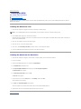
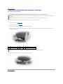
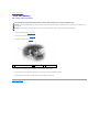
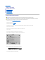
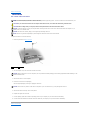
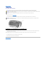
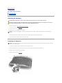
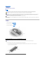
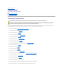
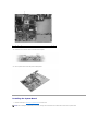
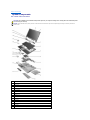
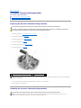
1
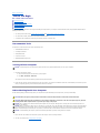
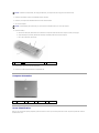
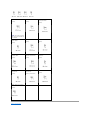
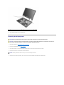
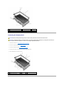
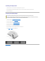
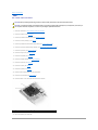
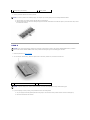
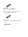
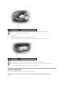
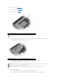
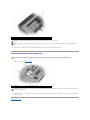
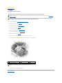
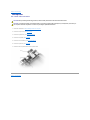
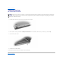
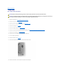
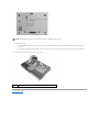
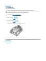
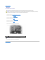
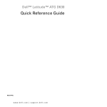
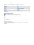
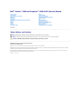
Dell™ Latitude™ D620 Service Manual
Before You Begin System Components Media Bay Devices Hard Drive Hinge Cover Keyboard Memory Display Assembly Internal Card with Bluetooth® Wireless Technology Communications Cards Coin-Cell Battery Palm Rest Modem Processor Thermal-Cooling Assembly Processor Module Speaker Microphone PC Card Reader System Board Fan Base Flashing the BIOS Model PP18L
Notes, Notices, and Cautions
NOTE: A NOTE indicates important information that helps you make better use of your computer.
NOTICE: A NOTICE indicates either potential damage to hardware or loss of data and tells you how to avoid the problem.
CAUTION: A CAUTION indicates a potential for property damage, personal injury, or death.
Information in this document is subject to change without notice.
© 2006 Dell Inc. All rights reserved.
Reproduction in any manner whatsoever without the written permission of Dell Inc. is strictly forbidden.
Trademarks used in this text: Dell, the DELL logo, and Latitude are trademarks of Dell Inc.; Microsoft and Windows are registered trademarks of Microsoft Corporation; Bluetooth is a
registered trademark owned by Bluetooth SIG, Inc. and is used by Dell under license;
Other trademarks and trade names may be used in this document to refer to either the entities claiming the marks and names or their products. Dell Inc. disclaims any
proprietary interest in trademarks and trade names other than its own.
November 2006 Rev. A01
Back to Contents Page
Base
Dell™ Latitude™ D620 Service Manual
CAUTION: Before performing the following procedures, follow the safety instructions in the Product Information Guide.
CAUTION: To prevent static damage to components inside your computer, discharge static electricity from your body before you touch any of
your computer's electronic components. You can do so by touching an unpainted metal surface.
1.
Follow the instructions in Before Working Inside Your Computer.
2.
Remove the hard drive (see Hard Drive).
3.
Remove any installed media bay device (see Media Bay Devices).
4.
Remove the memory module(s) (see Memory).
5.
Remove any installed wireless communications cards (see Communications Cards).
6.
Remove the processor thermal-cooling assembly (see Processor Thermal-Cooling Assembly).
7.
Remove the processor (see Processor Module).
8.
Remove the hinge cover (see Hinge Cover).
9.
Remove the keyboard (see Keyboard).
10.
Remove the display assembly (see Display Assembly).
11.
Remove the palm rest (see Palm Rest).
12.
Remove the modem (see Modem).
13.
Remove the speaker (see Speaker).
14.
Disconnect the fan power cable from the system board.
15.
Remove the system board (see System Board).
16.
Remove the fan (see Fan).
NOTE: If the base has the improved K-Lock, the K-Lock is held down with a screw. Remove and discard the screw when installing this base, as the
screw is not needed.
1
base with K-Lock assembly
Back to Contents Page
2
screw
Back to Contents Page
Before You Begin
Dell™ Latitude™ D620 Service Manual
Recommended Tools
Turning Off Your Computer
Before Working Inside Your Computer
Computer Orientation
Screw Identification
This chapter provides procedures for removing and installing the components in your computer. Unless otherwise noted, each procedure assumes that the
following conditions exist:
l
You have performed the steps in Turning Off Your Computer and Before Working Inside Your Computer.
l
You have read the safety information in the Product Information Guide.
l
A component can be replaced by performing the removal procedure in reverse order.
Recommended Tools
The procedures in this document may require the following tools:
l
Small flat-blade screwdriver
l
#1 Phillips screwdriver
l
Small plastic scribe
l
5-mm hex nut driver
l
Flash BIOS-update program CD
Turning Off Your Computer
NOTICE: To avoid losing data, save and close any open files and exit any open programs before you turn off your computer.
1.
Shut down the operating system:
a.
Save and close any open files and exit any open programs
b.
Click Start® Shut Down® Shut down.
The computer turns off after the operating system shutdown process finishes.
2.
Ensure that the computer and any attached devices are turned off. If your computer and attached devices do not automatically turn off when you shut
down your operating system, press and hold the power button for 4 seconds.
Before Working Inside Your Computer
Use the following safety guidelines to help protect your computer from potential damage and to help ensure your own personal safety.
CAUTION: Before you begin any of the procedures in this section, follow the safety instructions in the Product Information Guide.
CAUTION: Handle components and cards with care. Do not touch the components or contacts on a card. Hold a card by its edges or by its metal
mounting bracket. Hold a component such as a processor by its edges, not by its pins.
NOTICE: Only a certified service technician should perform repairs on your computer. Damage due to servicing that is not authorized by Dell is not
covered by your warranty.
NOTICE: When you disconnect a cable, pull on its connector or on its pull-tab, not on the cable itself. Some cables have a connector with locking tabs; if
you are disconnecting this type of cable, press in on the locking tabs before you disconnect the cable. As you pull connectors apart, keep them evenly
aligned to avoid bending any connector pins. Also, before you connect a cable, ensure that both connectors are correctly oriented and aligned.
NOTICE: To avoid damaging the computer, perform the following steps before you begin working inside the computer.
1.
Ensure that the work surface is flat and clean to prevent the computer cover from being scratched.
2.
Turn off your computer (see Turning Off Your Computer).
NOTICE: To disconnect a network cable, first unplug the cable from your computer and then unplug it from the network device.
3.
Disconnect any telephone, network, and USB cables from the computer.
4.
Disconnect your computer and all attached devices from their electrical outlets.
5.
Turn over the computer.
NOTICE: To avoid damaging the system board, you must remove the main battery before you service the computer.
6.
1
Remove the battery:
a.
Slide the two battery-bay latch releases on the bottom of the computer toward the sides of the computer until they are engaged.
b.
Grasp the battery by the battery tab and slide the battery horizontally toward the front of the computer.
c.
Lift to remove the battery from the bay.
battery
2
battery-bay latch release
3
7.
Press the power button to ground the system board.
8.
Remove any installed ExpressCards from the ExpressCard slot.
battery tab
Computer Orientation
1
front
2
left
3
back
4
right
Screw Identification
When you are removing and replacing components, print this section as a tool to lay out and keep track of the screws. The printout provides the number of
screws and their sizes.
Optical Drive:
Fan Module:
(1 each)
(4 each)
Display Assembly
to Computer Base:
(4 each)
NOTE: This screw is optional
and might not be installed on
the computer.
Modem to
System Board:
Display Bezel:
Display Panel:
(6 each)
(8 each)
Top of Palm Rest to
Computer Base:
Base Plastics to
Palm Rest From Bottom:
Hard Drive Carrier to
Hard Drive:
(3 each)
(7 each)
(2 each)
(2 each)
Speaker to
Base Plastics:
System Board to
Base Plastics:
(1 each)
(5 each, system board)
Display Hinges to Top Cover:
Keyboard to Palm Rest:
(3 each)
(2 each)
Back to Contents Page
Back to Contents Page
Flashing the BIOS
Dell™ Latitude™ D620 Service Manual
Flashing the BIOS From a CD
Flashing the BIOS From the Hard Drive
If a BIOS-update program CD is provided with the new system board, flash the BIOS from the CD. If you do not have a BIOS-update program CD, flash the
BIOS from the hard drive.
Flashing the BIOS From a CD
1.
Ensure that the AC adapter is plugged in and that the main battery is installed properly.
NOTE: If you use a BIOS-update program CD to flash the BIOS, set up the computer to boot from a CD before inserting the CD.
2.
Insert the BIOS-update program CD, and restart the computer.
Follow the instructions that appear on the screen. The computer continues to boot and updates the new BIOS. When the flash update is complete, the
computer will automatically reboot.
3.
Press <F2> during POST to enter the system setup program.
4.
Press <Alt> and <F> to reset the computer defaults.
5.
Press <Esc>, select Save changes and reboot, and press <Enter> to save configuration changes.
6.
Remove the flash BIOS-update program CD from the drive and restart the computer.
Flashing the BIOS From the Hard Drive
1.
Ensure that the AC adapter is plugged in, the main battery is properly installed, and a network cable is attached.
2.
Turn on the computer.
3.
Locate the latest BIOS update file for your computer at support.dell.com.
4.
Click Download Now to download the file.
5.
If the Export Compliance Disclaimer window appears, click Yes, I Accept this Agreement.
The File Download window appears.
6.
Click Save this program to disk and then click OK.
The Save In window appears.
7.
Click the down arrow to view the Save In menu, select Desktop, and then click Save.
The file downloads to your desktop.
8.
Click Close if the Download Complete window appears.
The file icon appears on your desktop and is titled the same as the downloaded BIOS update file.
9.
Double-click the file icon on the desktop and follow the instructions on the screen.
Back to Contents Page
Back to Contents Page
Internal Card with Bluetooth® Wireless Technology
Dell™ Latitude™ D620 Service Manual
CAUTION: Before performing the following procedures, follow the safety instructions in your Product Information Guide.
NOTICE: To avoid electrostatic discharge, ground yourself by using a wrist grounding strap or by periodically touching a connector on the back panel of
the computer.
NOTICE: To avoid damaging the system board, you must remove the main battery before you begin working inside the computer.
If you ordered an internal card with Bluetooth wireless technology with your computer, it is already installed.
1.
Follow the procedures in Before You Begin.
2.
Remove the hinge cover (see Hinge Cover).
3.
Gently pull left on the cable for the card with Bluetooth wireless technology.
4.
When there is enough clearance between the right edge of the card and the card holder, insert a plastic scribe and pry the card to the left until it is
released from the metal clip.
1
metal tab
2
card
3
card connector
4
card cable
NOTICE: Be careful when removing the card to avoid damaging the card, card cable, or surrounding components.
5.
Disconnect the card from the cable and remove the card from the computer.
Back to Contents Page
Back to Contents Page
Coin-Cell Battery
Dell™ Latitude™ D620 Service Manual
CAUTION: Before performing the following procedures, follow the safety instructions in your Product Information Guide.
NOTICE: To avoid electrostatic discharge, ground yourself by using a wrist grounding strap or by periodically touching a connector on the back panel of
the computer.
NOTICE: To avoid damaging the system board, you must remove the main battery before you begin working inside the computer.
1.
Follow the procedures in Before You Begin.
2.
Remove the hinge cover (see Hinge Cover).
3.
Remove the keyboard (see Keyboard).
1
coin-cell battery connector
plastic mylar
3
coin-cell battery
4.
Remove the coin-cell battery connector from the connector on the system board.
5.
Being careful not to break the plastic, slightly raise the corner of the plastic mylar above the battery.
6.
While holding the mylar, grasp the battery and pull out of the battery compartment.
Back to Contents Page
2
Back to Contents Page
Processor Module
Dell™ Latitude™ D620 Service Manual
Removing the Processor Module
Installing the Processor Module
Removing the Processor Module
CAUTION: Before performing the following procedures, follow the safety instructions in the Product Information Guide.
CAUTION: To prevent static damage to components inside your computer, discharge static electricity from your body before you touch any of
your computer's electronic components. You can do so by touching an unpainted metal surface.
NOTICE: Press and hold the processor down by applying slight pressure to the center of the processor while turning the cam screw to prevent
intermittent contact between the cam screw and processor.
NOTICE: To avoid damage to the processor, hold the screwdriver so that it is perpendicular to the processor when turning the cam screw.
1.
Follow the instructions in Before Working Inside Your Computer.
2.
Remove the hinge cover (see Hinge Cover).
3.
Remove the optical drive (see Media Bay Devices).
4.
Remove the keyboard (see Keyboard).
5.
Remove the coin-cell battery (see Coin-Cell Battery).
6.
Remove the palm rest (see Palm Rest).
7.
Remove the processor thermal-cooling assembly (see Processor Thermal-Cooling Assembly).
NOTICE: When removing the processor module, pull the module straight up. Be careful not to bend the pins on the processor module.
8.
To loosen the ZIF socket, use a small, flat-blade screwdriver and rotate the ZIF-socket cam screw counterclockwise until it comes to the cam stop.
The ZIF-socket cam screw secures the processor to the system board. Take note of the arrow on the ZIF-socket cam screw.
1
ZIF-socket cam screw
9.
2
ZIF-socket
3
pin-1 corner of processor
Use a processor extraction tool to remove the processor module.
Installing the Processor Module
NOTICE: Ensure that the cam lock is in the fully open position before seating the processor module. Seating the processor module properly in the ZIF
socket does not require force.
NOTICE: A processor module that is not properly seated can result in an intermittent connection or permanent damage to the processor and ZIF
socket.
1.
Align the pin-1 corner of the processor module so that it points to the triangle on the system board, and insert the processor module into the ZIF socket.
When the processor module is correctly seated, all four corners are aligned at the same height. If one or more corners of the module are higher than the
others, the module is not seated correctly.
NOTICE: Hold the processor down while turning the cam screw to prevent intermittent contact between the cam screw and processor.
2.
Tighten the ZIF socket by turning the cam screw clockwise to secure the processor module to the system board.
3.
Peel the backing off the thermal cooling pad and adhere the pad to the portion of the thermal-cooling assembly that covers the processor.
4.
Replace the processor thermal-cooling assembly (see Processor Thermal-Cooling Assembly).
5.
Replace the palm rest (see Palm Rest).
6.
Replace the coin-cell battery (see Coin-Cell Battery).
7.
Replace the keyboard (see Keyboard).
8.
Replace the optical drive (see Media Bay Devices).
9.
Replace the hinge cover (see Hinge Cover).
10.
Replace the battery.
11.
Update the BIOS using a flash BIOS-update program CD. See Flashing the BIOS From a CD.
Back to Contents Page
Back to Contents Page
Display Assembly
Dell™ Latitude™ D620 Service Manual
Removing the Display Assembly
Removing the Display Bezel
Removing the Display Panel
Installing the Display Panel
Removing the Display Hinges
Removing the Display Assembly
CAUTION: Before performing the following procedures, follow the safety instructions in the Product Information Guide.
CAUTION: To prevent static damage to components inside your computer, discharge static electricity from your body before you touch any of
your computer's electronic components. You can do so by touching an unpainted metal surface.
1.
Follow the instructions in Before Working Inside Your Computer.
2.
Remove the hinge cover (see Hinge Cover).
3.
Remove the keyboard (see Keyboard).
4.
Pull straight up on the pull-tab that is attached to the display-feed flex cable to disconnect the cable from the system board.
5.
Disconnect the antenna cable(s).
6.
Carefully remove the antenna cable and the display cables from their routing guides.
7.
Close the display.
8.
Turn the computer upside-down with the back of the computer facing you.
9.
From the bottom of the computer, remove the two M2.5 x 8-mm screws labeled "D."
10.
From the back of the computer, remove the two M2.5 x 8-mm screws.
11.
Turn the computer right-side up and open the display.
1
antenna cables
12.
2
display cable
Lift the display assembly out of the computer base.
Removing the Display Bezel
CAUTION: Before performing the following procedures, follow the safety instructions in the Product Information Guide.
CAUTION: To prevent static damage to components inside your computer, discharge static electricity from your body before you touch any of
your computer's electronic components. You can do so by touching an unpainted metal surface.
1.
Follow the instructions in Before Working Inside Your Computer.
2.
Remove the display assembly (see Display Assembly).
3.
Use a plastic scribe to pry the six circular screw covers/bumpers out of the screw holes on the front of the bezel.
4.
Remove the six M2.5 x 5-mm screws from the front of the bezel.
NOTICE: Carefully separate the bezel from the top cover to avoid damage to the bezel.
5.
Starting from the inside edges of bezel, use your fingers to pry the bezel upward and outward from the display panel.
1
screw covers/display bumpers (6)
2
M2.5 x 5-mm screws (6)
3
display bezel
4
top cover
Removing the Display Panel
CAUTION: Before performing the following procedures, follow the safety instructions in the Product Information Guide.
CAUTION: To prevent static damage to components inside your computer, discharge static electricity from your body before you touch any of
your computer's electronic components. You can do so by touching an unpainted metal surface.
1.
Follow the instructions in Before Working Inside Your Computer.
2.
Remove the display assembly (see Display Assembly).
3.
Remove the display bezel (see Removing the Display Bezel).
4.
Remove the four M2 x 3-mm screws from each side of the display panel.
5.
Lift the display panel out of the top cover.
1
display panel
2
top cover
3
M2 x 3-mm screws (4)
4
notches for cable routing
Installing the Display Panel
1.
Replace the eight M2 x 3-mm screws that secure the display panel to the top cover.
2.
Route the display-feed flex cable and antenna cables so that they rest in the notch located in the bottom edge of the top cover.
3.
Replace the display bezel.
Removing the Display Hinges
CAUTION: Before performing the following procedures, follow the safety instructions in the Product Information Guide.
CAUTION: To prevent static damage to components inside your computer, discharge static electricity from your body before you touch any of
your computer's electronic components. You can do so by touching an unpainted metal surface.
1.
Follow the instructions in Before Working Inside Your Computer.
2.
Remove the display assembly (see Display Assembly).
3.
Remove the display bezel (see Removing the Display Bezel).
4.
Remove the display Panel (see Removing the Display Panel).
5.
Remove the M2.5 x 5-mm screw from the right display hinge.
6.
Lift the right display hinge off the two alignment pins and out of the top cover.
7.
Repeat step 5 and step 6 for the left display hinge.
1
M2.5 x 5-mm screw
2
right display hinge
3
alignment pins (2)
4
top cover
Back to Contents Page
Back to Contents Page
Fan
Dell™ Latitude™ D620 Service Manual
CAUTION: Before performing the following procedures, follow the safety instructions in the Product Information Guide.
CAUTION: To prevent static damage to components inside your computer, discharge static electricity from your body before you touch any of
your computer's electronic components. You can do so by touching an unpainted metal surface.
1.
Follow the instructions in Before Working Inside Your Computer.
2.
Remove the hard drive (see Hard Drive).
3.
Remove any installed media bay device (see Media Bay Devices).
4.
Remove the memory module(s) (see Memory).
5.
Remove any installed wireless communications cards (see Communications Cards).
6.
Remove the processor thermal-cooling assembly (see Processor Thermal-Cooling Assembly).
7.
Remove the processor (see Processor Module).
8.
Remove the hinge cover (see Hinge Cover).
9.
Remove the keyboard (see Keyboard).
10.
Remove the display assembly (see Display Assembly).
11.
Remove the palm rest (see Palm Rest).
12.
Remove the modem (see Modem).
13.
Remove the speaker (see Speaker).
14.
Disconnect the fan power cable from the system board.
15.
Remove the system board (see System Board).
16.
Remove the M2.5 x 5-mm screw that secures the fan to the base.
1
17.
fan assembly
2
Lift the fan assembly out of the base.
M2.5 x 5-mm screw
Back to Contents Page
Back to Contents Page
Hard Drive
Dell™ Latitude™ D620 Service Manual
NOTE: You need the Operating System CD to install the Microsoft® Windows® operating system. You also need the Drivers and Utilities CD for your
computer to install the drivers and utilities on the new hard drive.
CAUTION: If you remove the hard drive from the computer when the drive is hot, do not touch the metal housing of the hard drive.
CAUTION: Before working inside your computer, follow the safety instructions in the Product Information Guide.
NOTICE: To prevent data loss, turn off your computer before removing the hard drive. Do not remove the hard drive while the computer is on, in
standby mode, or in hibernate mode.
NOTICE: Hard drives are extremely fragile; even a slight bump can damage the drive.
NOTE: Dell does not guarantee compatibility or provide support for hard drives from sources other than Dell.
To replace the hard drive in the hard drive bay:
1.
Follow the procedures in Before You Begin.
1 screws (2) 2 hard drive
2.
Turn the computer over, and remove the two hard drive screws.
NOTICE: When the hard drive is not in the computer, store it in protective antistatic packaging. See "Protecting Against Electrostatic Discharge" in the
Product Information Guide.
3.
Slide the hard drive out of the computer.
4.
Remove the new drive from its packaging.
Save the original packaging for storing or shipping the hard drive.
NOTICE: Use firm and even pressure to slide the drive into place. If you use excessive force, you may damage the connector.
5.
Slide the hard drive into the bay until it is fully seated.
6.
Replace and tighten the two screws.
7.
Use the Operating System CD to install the operating system for your computer (see your User's Guide for information).
8.
Use the Drivers and Utilities CD to install the drivers and utilities for your computer (see your User's Guide for information).
Back to Contents Page
Back to Contents Page
Hinge Cover
Dell™ Latitude™ D620 Service Manual
CAUTION: Before you begin any of the procedures in this section, follow the safety instructions in the Product Information Guide.
NOTICE: To avoid electrostatic discharge, ground yourself by using a wrist grounding strap or by periodically touching an unpainted metal surface (such
as a connector on the back of the computer).
NOTICE: The hinge cover is fragile and can be damaged if extreme force is used. Be careful when removing the hinge cover.
1.
Follow the procedures in Before You Begin.
2.
Turn the computer top-side up, and then open the display all the way (180 degrees) so that the display rests on your work surface.
NOTICE: To avoid damaging the hinge cover, do not lift the cover on both sides simultaneously. Removing the hinge cover in a different way than
described may cause the plastic to break.
1
hinge cover
3.
2
plastic scribe
3
indent
Starting on the right side of the computer, use a plastic scribe to pry up the hinge cover. Lift the cover away from the computer going from the right
toward the left, and lay the cover aside.
Before installing the hinge cover, ensure that all cables are routed correctly. Improper routing of the cables can cause damage to the cables.
4.
To replace the hinge cover, insert the left edge of the cover into place.
5.
Press from left to right until the cover snaps into place.
Back to Contents Page
Back to Contents Page
Keyboard
Dell™ Latitude™ D620 Service Manual
Removing the Keyboard
Replacing the Keyboard
Removing the Keyboard
CAUTION: Before working inside your Dell™ computer, follow the safety instructions in your Product Information Guide.
CAUTION: To prevent static damage to components inside your computer, discharge static electricity from your body before you touch any of
your computer's electronic components. You can do so by touching an unpainted metal surface.
1.
Follow the instructions in Before Working Inside Your Computer.
2.
Remove the hinge cover (see Hinge Cover).
3.
Remove the three screws at the top of the keyboard.
NOTICE: The keycaps on the keyboard are fragile, easily dislodged, and time-consuming to replace. Be careful when removing and handling the
keyboard.
4.
Lift the keyboard and rotate it slightly forward to allow access to the keyboard connector on the system board.
5.
Disconnect the keyboard cable connector from the system board.
Replacing the Keyboard
NOTICE: To avoid scratching the palm rest when replacing the keyboard, hook the tabs along the front edge of the keyboard into the palm rest, and
then secure the keyboard in place.
1.
To replace the keyboard, connect the keyboard connector to the system board.
2.
Place the tabs along the front edge of the keyboard into the palm rest and lay the keyboard down on the palm rest.
3.
Replace the three screws at the top of the keyboard.
4.
Replace the hinge cover (see Hinge Cover).
1
keyboard
Back to Contents Page
2
system board connector
Back to Contents Page
Memory
Dell™ Latitude™ D620 Service Manual
DIMM A
DIMM B
CAUTION: Before you begin any of the procedures in this section, follow the safety instructions in the Product Information Guide.
NOTICE: If your computer has only one memory module, install the memory module in the connector labeled "DIMMA."
NOTICE: If you remove your original memory modules from the computer during a memory upgrade, keep them separate from any new modules that
you may have, even if you purchased the new modules from Dell. If possible, do not pair an original memory module with a new memory module.
Otherwise, your computer may not function at optimal performance.
NOTE: Memory modules purchased from Dell are covered under your computer warranty.
Your computer has two user-accessible SODIMM sockets, one accessed from beneath the keyboard (DIMM A), and the other accessed from the bottom of the
computer (DIMM B).
DIMM A
1.
Follow the procedures in Before You Begin.
2.
Remove the hinge cover (see Hinge Cover).
3.
Remove the keyboard (see Keyboard).
1
memory module (DIMM A)
2
securing clips (2)
NOTICE: To prevent damage to the memory module connector, do not use tools to spread the memory-module securing clips.
4.
If you are replacing a memory module, ground yourself and remove the existing module:
a.
Use your fingertips to carefully spread apart the securing clips on each end of the memory module connector until the module pops up.
b.
Remove the module from the connector.
1
securing clips (2 per connector)
5.
2
memory module
Ground yourself and install the new memory module:
NOTE: If the memory module is not installed properly, the computer may not boot properly. No error message indicates this failure.
a.
Align the notch in the module connector with the tab in the connector slot.
b.
Slide the module firmly into the slot at a 45-degree angle, and rotate the module down until it clicks into place. If you do not feel the click, remove
the module and reinstall it.
DIMM B
NOTICE: If you need to install memory modules in two connectors, install a memory module in the connector labeled "DIMMA" before you install a
module in the connector labeled "DIMMB." Insert memory modules at a 45-degree angle to avoid damaging the connector.
1.
Follow the procedures in Before You Begin.
2.
Turn the computer bottom-side up, loosen the captive screw in the memory module cover, and then remove the cover.
1
memory module cover
2
captive screw
NOTICE: To prevent damage to the memory module connector, do not use tools to spread the memory-module securing clips.
3.
If you are replacing a memory module, ground yourself and remove the existing module:
a.
Use your fingertips to carefully spread apart the securing clips on each end of the memory module connector until the module pops up.
b.
Remove the module from the connector.
1
securing clips (2 per connector)
2
memory module
NOTICE: Insert memory modules at a 45-degree angle to avoid damaging the connector.
4.
Ground yourself and install the new memory module:
NOTE: If the memory module is not installed properly, the computer may not boot properly. No error message indicates this failure.
5.
a.
Align the notch in the module edge connector with the tab in the connector slot.
b.
Slide the module firmly into the slot at a 45-degree angle, and rotate the module down until it clicks into place. If you do not feel the click, remove
the module and reinstall it.
Replace the memory module cover.
NOTICE: If the cover is difficult to close, remove the module and reinstall it. Forcing the cover to close may damage your computer.
6.
Insert the battery into the battery bay, or connect the AC adapter to your computer and an electrical outlet.
7.
Turn on the computer.
As the computer boots, it detects the additional memory and automatically updates the system configuration information.
To confirm the amount of memory installed in the computer, click Start® Help and Support® Use Tools to view your computer information and
diagnose problems® My Computer Information.
Back to Contents Page
Back to Contents Page
Communications Cards
Dell™ Latitude™ D620 Service Manual
Wireless Local Area Network (WLAN) Card
Mobile Broadband Card
Subscriber Identity Module (SIM) Card
Wireless Local Area Network (WLAN) Card
If you ordered a WLAN card with your computer, the card is already installed.
CAUTION: Before you begin any of the procedures in this section, follow the safety instructions in the Product Information Guide.
1.
Follow the procedures in Before You Begin.
2.
Remove the hinge cover (see Hinge Cover).
3.
Remove the keyboard (see Keyboard).
1
WLAN card
2
antenna cables (2)
NOTICE: To prevent damage to the connector, do not use tools to spread the securing clips.
4.
If a WLAN card is not already installed, go to step 5. If you are replacing a WLAN card, remove the existing card:
a.
Disconnect the WLAN card from any attached cables.
b.
Use your fingertips to carefully spread apart the metal securing tabs until the card pops up slightly.
c.
Slide and lift the WLAN card out of its connector.
1
WLAN card
2
metal securing tabs (2)
NOTICE: The connectors are keyed to ensure correct insertion. If you feel resistance, check the connectors and realign the card.
NOTE: Do not insert a Mobile Broadband card into the WLAN card slot.
5.
1
To install a WLAN card:
a.
Move any antenna cables out of the way to make space for the WLAN card.
b.
Align the WLAN card with the connector at a 45-degree angle, and press the card into the connector until you feel a click.
WLAN card
2
antenna cable connectors
NOTICE: To avoid damaging the WLAN card, never place cables on top of or under the card.
NOTE: Your WLAN card may have two or three antenna cable connectors, depending on the type of card you ordered.
NOTE: For more specific information about which cable to connect to which connector, see the documentation that came with your WLAN card.
c.
Connect the antenna cables to the WLAN card, ensuring that you route the cables correctly.
Mobile Broadband Card
If you ordered a Mobile Broadband card with your computer, the card is already installed.
CAUTION: Before you begin any of the procedures in this section, follow the safety instructions in the Product Information Guide.
1.
Follow the procedures in Before You Begin.
2.
Remove the hinge cover (see Hinge Cover).
3.
Remove the keyboard (see Keyboard).
1
Mobile Broadband card
2
antenna wires (2)
NOTICE: To prevent damage to the connector, do not use tools to spread the securing clips.
4.
If a Mobile Broadband card is not already installed, go to step 5. If you are replacing a Mobile Broadband card, remove the existing card:
a.
1
Disconnect the Mobile Broadband card from any attached cables.
Mobile Broadband card
2
metal securing tabs (2)
b.
Use your fingertips to carefully spread apart the metal securing tabs until the card pops up slightly.
c.
Slide and lift the Mobile Broadband card out of its connector.
NOTICE: The connectors are keyed to ensure correct insertion. If you feel resistance, check the connectors and realign the card.
NOTE: Do not insert a WLAN card into the Mobile Broadband card slot.
NOTICE: The Mobile Broadband card may have one or two connectors, depending on the type of card you ordered.
5.
To install a Mobile Broadband card:
a.
Move any antenna cables out of the way to make space for the Mobile Broadband card.
b.
Align the card with the connector at a 45-degree angle, and press the card into the connector until you feel a click.
1
Mobile Broadband card
2
antenna wires (2)
NOTICE: To avoid damaging the Mobile Broadband card, never place cables on top of or under the card.
NOTE: For more specific information about which cable to connect to which connector, see the documentation that came with your Mobile Broadband
card.
6.
Connect the antenna cable or cables to the Mobile Broadband card, ensuring that you route the cables correctly.
Subscriber Identity Module (SIM) Card
CAUTION: Before you begin any of the procedures in this section, follow the safety instructions in the Product Information Guide.
1.
1
Follow the procedures in Before You Begin.
SIM card
2
metal brackets (2)
NOTICE: Do not touch the SIM card connectors to protect the card from electrostatic discharge (ESD). To prevent ESD, hold the card in your hand before
you insert or remove the card.
2.
With the cut-off corner on the card facing away from the card compartment, insert the SIM card into the compartment so that it slides under the metal
tabs on the sides.
Back to Contents Page
Back to Contents Page
Modem
Dell™ Latitude™ D620 Service Manual
CAUTION: Before you begin the following procedure, see the safety instructions in the Product Information Guide.
NOTICE: To avoid damaging the system board, you must remove the main battery before you begin working inside the computer (see Before Working
Inside Your Computer).
CAUTION: To prevent static damage to components inside your computer, discharge static electricity from your body before you touch any of
your computer's electronic components. You can do so by touching an unpainted metal surface.
1.
Follow the instructions in Before Working Inside Your Computer.
2.
Remove the hinge cover (see Hinge Cover).
3.
Remove the optical drive (see Media Bay Devices).
4.
Remove the keyboard (see Keyboard).
5.
Remove the coin-cell battery (see Coin-Cell Battery).
6.
Remove the display assembly (see Display Assembly).
7.
Remove the palm rest (see Palm Rest).
8.
Remove the M2 x 3-mm screw that attaches the modem to the system board.
9.
Pull up on the pull-tab to disconnect the modem from the connector on the system board.
1
modem pull-tab
2
M2 x 3-mm screw
3
modem cable
4
system board connector
NOTICE: Do not disconnect the modem cable from the system board.
10.
Disconnect the modem cable from the modem.
Back to Contents Page
Back to Contents Page
Microphone
Dell™ Latitude™ D620 Service Manual
CAUTION: Before performing the following procedures, follow the safety instructions in the Product Information Guide.
CAUTION: To prevent static damage to components inside your computer, discharge static electricity from your body before you touch any of
your computer's electronic components. You can do so by touching an unpainted metal surface.
1.
Follow the instructions in Before Working Inside Your Computer.
2.
Remove the hinge cover (see Hinge Cover).
3.
Remove the optical drive (see Media Bay Devices).
4.
Remove the keyboard (see Keyboard).
5.
Remove the coin-cell battery (see Coin-Cell Battery).
6.
Remove the palm rest (see Palm Rest).
7.
Disconnect the microphone board from the system board.
Back to Contents Page
Back to Contents Page
Media Bay Devices
Dell™ Latitude™ D620 Service Manual
NOTE: If the device security screw is not present, you can remove and install devices while the computer is running and connected to a docking device
(docked).
NOTICE: To prevent damage to devices, store them in a safe, dry place when they are not installed in the computer. Avoid pressing down on them or
placing heavy objects on top of them.
1.
If present, remove the device security screw from the bottom of the computer.
2.
If the computer is running, double-click the Safely Remove Hardware icon on the taskbar, click the device you want to eject, and click Stop.
3.
Press the device latch release.
4.
Pull the device out of the media bay.
To install a device, push the new device into the bay until it clicks into place.
Back to Contents Page
Back to Contents Page
Palm Rest
Dell™ Latitude™ D620 Service Manual
CAUTION: Before performing the following procedures, follow the safety instructions in the Product Information Guide.
CAUTION: To prevent static damage to components inside your computer, discharge static electricity from your body before you touch any of
your computer's electronic components. You can do so by touching an unpainted metal surface.
1.
Follow the instructions in Before Working Inside Your Computer.
2.
Remove the hinge cover (see Hinge Cover).
3.
Remove any devices installed in the media bay (see Media Bay Devices).
4.
Remove the keyboard (see Keyboard).
5.
Remove the display assembly (see Display Assembly).
6.
Remove the internal card with Bluetooth® wireless technology (see Internal Card with Bluetooth® Wireless Technology).
7.
Remove the coin-cell battery (see Coin-Cell Battery).
8.
Remove the three screws labeled "P" from the top of the palm rest.
9.
Turn the computer upside-down.
10.
Remove the hard drive (see Hard Drive).
11.
Loosen the two captive screws located at the front of the hard drive bay.
12.
Remove the seven M2.5 x 8-mm screws from the bottom of the computer.
NOTICE: Carefully separate the palm rest from the base plastics to avoid damage to the palm rest.
13.
14.
1
Remove the palm rest.
a.
Starting at the back center of the palm rest, use your fingers to separate the palm rest from the base plastics by lifting the inside edge of the
palm rest.
b.
After the back of the palm rest is unsnapped, push the palm rest forward to unhook the remainder of the palm rest from the front of the base.
Disconnect the touch pad connector from the system board.
touch pad connector
Back to Contents Page
Back to Contents Page
PC Card Reader
Dell™ Latitude™ D620 Service Manual
CAUTION: Before performing the following procedures, follow the safety instructions in the Product Information Guide.
CAUTION: To prevent static damage to components inside your computer, discharge static electricity from your body before you touch any of
your computer's electronic components. You can do so by touching an unpainted metal surface.
1.
Follow the instructions in Before Working Inside Your Computer.
2.
Remove the hinge cover (see Hinge Cover).
3.
Remove the optical drive (see Media Bay Devices).
4.
Remove the keyboard (see Keyboard).
5.
Remove the coin-cell battery (see Coin-Cell Battery).
6.
Remove the palm rest (see Palm Rest).
7.
Remove the four M2 x 3-mm screws that secure the PC Card reader to the computer.
8.
Use the pull-tab to disconnect the PC Card reader connector from the system board.
Back to Contents Page
Back to Contents Page
Speaker
Dell™ Latitude™ D620 Service Manual
CAUTION: Before performing the following procedures, follow the safety instructions in the Product Information Guide.
CAUTION: To prevent static damage to components inside your computer, discharge static electricity from your body before you touch any of
your computer's electronic components. You can do so by touching an unpainted metal surface.
1.
Follow the instructions in Before Working Inside Your Computer.
2.
Remove the hinge cover (see Hinge Cover).
3.
Remove the optical drive (see Media Bay Devices).
4.
Remove the keyboard (see Keyboard).
5.
Remove the coin-cell battery (see Coin-Cell Battery).
6.
Remove the palm rest (see Palm Rest).
7.
Disconnect the speaker connector from the system board.
1
speaker connector
NOTICE: Handle the speakers with care to avoid damaging them.
8.
Pull the speaker straight up and out of the base plastics.
Back to Contents Page
Back to Contents Page
System Board
Dell™ Latitude™ D620 Service Manual
Removing the System Board
Installing the System Board
Removing the System Board
CAUTION: Before performing the following procedures, follow the safety instructions in the Product Information Guide.
CAUTION: To prevent static damage to components inside your computer, discharge static electricity from your body before you touch any of
your computer's electronic components. You can do so by touching an unpainted metal surface.
The system board's BIOS chip contains the Service Tag, which is also visible on a barcode label on the bottom of the computer. The replacement kit for the
system board includes a CD that provides a utility for transferring the Service Tag to the replacement system board.
1.
Follow the instructions in Before Working Inside Your Computer.
2.
Remove the hinge cover (see Hinge Cover).
3.
Remove the keyboard (see Keyboard).
4.
Remove the display assembly (see Display Assembly).
5.
Remove the hard drive (see Hard Drive).
6.
Remove the optical drive (see Media Bay Devices).
7.
Remove the memory module (see Memory).
8.
Remove and installed wireless communications cards (see Communications Cards).
9.
Remove the palm rest (see Palm Rest).
10.
Remove the modem (see Modem).
11.
Remove the speaker (see Speaker).
12.
Remove the PC Card reader (see PC Card Reader).
13.
Remove the processor thermal-cooling assembly (see Processor Thermal-Cooling Assembly).
14.
Remove the processor (see Processor Module).
15.
Remove the microphone (see Microphone.)
16.
Disconnect the fan cable from the system board.
17.
Disconnect the cables near the WLAN card and the modem connector from the system board.
18.
Remove the three M2.5 x 5-mm system board screws from the bottom of the computer.
1
M2.5 x 5-mm screws (5)
19.
Remove the four 5-mm hex screws on the back of the computer.
20.
Lift the system board out and away from the base plastics.
Installing the System Board
1.
Perform all the steps in Removing the System Board in reverse order.
NOTE: When installing the system board, ensure that you align the wireless switch on the base with the switch on the system board.
2.
Insert the battery into the battery bay. See Before Working Inside Your Computer.
3.
Connect the AC adapter to the computer and to an electrical outlet.
NOTICE: Before turning on the computer, replace all screws and ensure that no stray screws remain inside the computer. Failure to do so may result in
damage to the computer.
4.
Turn on the computer.
NOTE: After replacing the system board, enter the computer Service Tag into the BIOS of the replacement system board.
5.
Insert the CD that accompanied the replacement system board into the appropriate drive. Follow the instructions on the screen.
Back to Contents Page
Back to Contents Page
System Components
Dell™ Latitude™ D620 Service Manual
CAUTION: Only a certified service technician should perform repairs on your computer. Damage due to servicing that is not authorized by Dell is
not covered by your warranty.
NOTICE: Unless otherwise noted, each procedure in this document assumes that a part can be replaced by performing the removal procedure in
reverse order.
1
display latch
2
display
3
hinge cover
4
keyboard
5
palm rest
6
fan assembly
7
system board
8
base plastics
9
optical drive
10
battery
11
speaker
12
hard drive
13
coin-cell battery
14
modem
15
processor
16
internal card with Bluetooth® wireless technology
17
processor thermal-cooling assembly
18
Mobile Broadband card
19
WLAN card
20
display-feed flex cable
21
antenna cables
22
display hinge
Back to Contents Page
Back to Contents Page
Processor Thermal-Cooling Assembly
Dell™ Latitude™ D620 Service Manual
Removing the Processor Thermal-Cooling Assembly
Replacing the Processor Thermal-Cooling Assembly
Removing the Processor Thermal-Cooling Assembly
CAUTION: Before performing the following procedures, follow the safety instructions in the Product Information Guide.
CAUTION: To prevent static damage to components inside your computer, discharge static electricity from your body before you touch any of
your computer's electronic components. You can do so by touching an unpainted metal surface.
1.
Follow the instructions in Before Working Inside Your Computer.
2.
Remove the hinge cover (see Hinge Cover).
3.
Remove the optical drive (see Media Bay Devices).
4.
Remove the keyboard (see Keyboard).
5.
Remove the coin-cell battery (see Coin-Cell Battery).
6.
Remove the palm rest (see Palm Rest).
1
processor thermal-cooling assembly
2
captive screws (4)
NOTE: The processor thermal-cooling assembly may differ in appearance, depending on your computer configuration. However, the removal procedure is
the same for all assemblies.
7.
Loosen in consecutive order the four captive screws, labeled "1" through "4," on the assembly.
8.
Lift the assembly out of the computer.
Replacing the Processor Thermal-Cooling Assembly
CAUTION: Before performing the following procedures, follow the safety instructions in the Product Information Guide.
NOTE: To prevent static damage to components inside your computer, discharge static electricity from your body before you touch any of your
computer's electronic components. You can do so by touching an unpainted metal surface.
1.
Remove the processor thermal-cooling assembly (see Processor Thermal-Cooling Assembly).
NOTE: The original pad can be reused if the original processor and heat sink are reinstalled together. If either the processor or heat sink is replaced,
use the thermal pad provided in the kit to ensure that thermal conductivity is achieved.
2.
Peel the backing off the thermal cooling pad and adhere the pad to the portion of the thermal-cooling assembly that covers the processor.
3.
Place the assembly on the system board.
4.
Tighten in consecutive order the four captive screws, labeled "1" through "4," on the thermal-cooling assembly.
5.
Replace the palm rest (see Palm Rest).
6.
Replace the coin-cell battery (see Coin-Cell Battery).
7.
Replace the keyboard (see Keyboard).
8.
Replace the optical drive (see Media Bay Devices).
9.
Replace the hinge cover (see Hinge Cover).
10.
Replace the battery.
Back to Contents Page
Back to Contents Page
Dell™ Latitude™ D620 Service Manual
NOTE: A NOTE indicates important information that helps you make better use of your computer.
NOTICE: A NOTICE indicates either potential damage to hardware or loss of data and tells you how to avoid the problem.
CAUTION: A CAUTION indicates a potential for property damage, personal injury, or death.
Information in this document is subject to change without notice.
© 2006 Dell Inc. All rights reserved.
Reproduction in any manner whatsoever without the written permission of Dell Inc. is strictly forbidden.
Trademarks used in this text: Dell, the DELL logo, and Latitude are trademarks of Dell Inc.; Microsoft and Windows are registered trademarks of Microsoft Corporation; Bluetooth is a
registered trademark owned by Bluetooth SIG, Inc. and is used by Dell under license;
Other trademarks and trade names may be used in this document to refer to either the entities claiming the marks and names or their products. Dell Inc. disclaims any
proprietary interest in trademarks and trade names other than its own.
November 2006 Rev. A01
Back to Contents Page