1
Dell™ Latitude™ C600/C500 User's Guide
About Your Computer
What You Need to Know
Features and Options
Setup and Operation
Using Your Computer
Connecting Devices
Microsoft® Windows® XP Features
Using Intel® SpeedStep™ to Set
Performance Levels
Passwords and Security
Traveling With Your Computer
Removing and Replacing Parts
Reinstalling Software
Solving Problems
Finding Solutions
Dell Diagnostics Understanding Error Messages
Getting Help
Technical Specifications
Additional Information
Regulatory Notices
Limited Warranty and Return Policy
Powering Your Computer
AC Adapter and Battery Power Management and Conservation Using the System Setup Program
Model PP01L
Notes, Notices, and Cautions
Notes, notices, and cautions are used as follows:
NOTE: A NOTE indicates important information that helps you make better use of your computer. NOTICE: A NOTICE indicates either potential damage to hardware or loss of data and
tells you how to avoid the problem. CAUTION: A CAUTION indicates a potential for property damage, personal injury,
or death.
Information in this document is subject to change without notice.
© 2000–2001 Dell Computer Corporation. All rights reserved.
Reproduction in any manner whatsoever without the written permission of Dell Computer Corporation is strictly forbidden.
Trademarks used in this text: Dell, the DELL logo, Latitude, Inspiron, OptiPlex, Dell Precision, ExpressCharge, HyperCool,
DellWare, and AccessDirect are trademarks of Dell Computer Corporation; Microsoft, Windows, Windows NT, and MS-DOS are
registered trademarks of Microsoft Corporation; 3Com is a registered trademark of 3Com Corporation; Intel and Pentium are
registered trademarks, and SpeedStep and Celeron are trademarks of Intel Corporation. As an ENERGY STAR partner, Dell has
determined that this product meets the ENERGY STAR guidelines for energy efficiency.
Other trademarks and trade names may be used in this document to refer to either the entities claiming the marks and names or
their products. Dell disclaims any proprietary interest in trademarks and trade names other than its own.
September 2001 368FN A02 Back to Contents Page
What You Need to Know: Dell™ Latitude™ C600/C500
User's Guide
Finding Information
When Using Your Computer
Safety and EMC Symbols
Ergonomic Computing Habits
Safety Instructions
When Removing or Installing Memory Modules
EMC Instructions
Protecting Against Electrostatic Discharge
Finding Information
Besides this User's Guide, the following documentation is included with your computer.
NOTE: Documentation updates are sometimes included with your computer to describe changes to
your computer or software. Always read these updates before consulting any other documentation
because the updates contain the latest information. An operating system Setup Guide, which describes how to set up the operating system installed on
your Dell computer.
Operating system documentation is included if you ordered your operating system from Dell. This
documentation describes how to configure and use your operating system software.
Online documentation for your computer's devices (such as a modem) and for options you purchase
separately from your computer. In Microsoft® Windows® XP, click the Start button, and then click Help and Support. From
the Help and Support window, click the link to access the user and system guides.
In Windows 2000, double-click the Dell User's Guide icon on the desktop, click System
Information, and then click System Documentation.
Readme files may be installed on your hard-disk drive to provide last-minute updates about technical
changes to your computer or advanced technical reference material intended for experienced users or
technicians.
For detailed information on the computer's parts and assemblies and how to remove and replace them, see
the computer Service Manual at the Dell support Web site at http://support.dell.com.
Safety and EMC Symbols
The following information defines the meaning of additional symbols used only in the Safety and
Electromagnetic Compatibility (EMC) Instructions.
Risk of explosion
Aircraft
Risk of fire
Use of this feature may be prohibited on aircraft
Risk of electric shock
Safety Instructions
General
Do not attempt to service the computer yourself unless you are a trained service
technician. Always follow installation instructions closely.
If you use an extension power cable with your AC adapter, ensure that the total ampere
rating of the products plugged in to the extension power cable does not exceed the
ampere rating of the extension cable.
Do not push objects into air vents or openings of your computer. Doing so can cause fire
or electric shock by shorting out interior components.
Place the AC adapter in a ventilated area, such as a desk top or on the floor, when you
use it to run the computer or to charge the battery. Do not cover the AC adapter with
papers or other items that will reduce cooling; also, do not use the AC adapter inside a
carrying case.
Do not allow your portable computer to operate with the base resting directly on
exposed skin for extended periods of time. The surface temperature of the base will rise
during normal operation (particularly when AC power is present). Allowing sustained
contact with the skin can cause discomfort or, eventually, a burn.
Do not use your computer in a wet environment, for example, near a bath tub, sink, or
swimming pool or in a wet basement.
If your computer includes an integrated or optional (PC Card) modem, disconnect the
modem cable if an electrical storm is approaching to avoid the remote risk of electric
shock from lightning via the telephone line.
To help avoid the potential hazard of electric shock, do not connect or disconnect any
cables or perform maintenance or reconfiguration of this product during an electrical
storm. Do not use your computer during an electrical storm unless all cables have been
disconnected and the computer is operating on battery power.
If your computer includes a modem, the cable used with the modem should be
manufactured with a minimum wire size of 26 American wire gauge (AWG) and an FCC-
compliant RJ-11 modular plug.
PC Cards may become very warm during normal operation. Use care when removing
PC Cards after their continuous operation.
Before you clean your computer, remove power. Clean your computer with a soft cloth
dampened with water. Do not use liquid or aerosol cleaners, which may contain
flammable substances.
Power (Safety Instructions, continued)
Use only the Dell-provided AC adapter approved for use with this computer. Use of
another AC adapter may cause a fire or explosion.
Before you connect the computer to an electrical outlet, check the AC adapter voltage
rating to ensure that the required voltage and frequency match the available power
source.
To remove power from the computer, turn it off, remove the battery pack, and
disconnect the AC adapter from the electrical outlet.
To help prevent electric shock, plug the AC adapter and peripheral power cables into
properly grounded power sources. These power cables may be equipped with threeprong plugs to provide an earth grounding connection. Do not use adapter plugs or
remove the grounding prong from the power cable plug. If you use a power extension
cable, use the appropriate type, two-prong or three-prong, to mate with the AC adapter
power cable.
Be sure that nothing rests on your AC adapter's power cable and that the cable is not
located where it can be tripped over or stepped on.
If you are using a multiple-outlet power strip, use caution when plugging the AC
adapter's power cable into the power strip. Some power strips may allow you to insert
the plug incorrectly. Incorrect insertion of the power plug could result in permanent
damage to your computer, as well as risk of electric shock and/or fire. Ensure that the
ground prong of the power plug is inserted into the mating ground contact of the power
strip.
Battery (Safety Instructions, continued)
Use only Dell battery modules that are approved for use with this computer. Use of other
types may increase the risk of fire or explosion.
Do not carry a battery pack in your pocket, purse, or other container where metal objects
(such as car keys or paper clips) could short-circuit the battery terminals. The resulting
excessive current flow can cause extremely high temperatures and may result in
damage to the battery pack or cause fire or burns.
The battery poses a burn hazard if you handle it improperly. Do not disassemble it.
Handle a damaged or leaking battery pack with extreme care. If the battery is damaged,
electrolyte may leak from the cells and may cause personal injury.
Keep the battery away from children.
Do not store or leave your computer or battery pack near a heat source such as a
radiator, fireplace, stove, electric heater, or other heat-generating appliance. When
heated to excessive temperatures, battery cells could explode or vent, posing a risk of
fire.
Do not dispose of your computer's battery in a fire or with normal household waste.
Battery cells may explode. Discard a used battery according to the manufacturer's
instructions or contact your local waste disposal agency for disposal instructions.
Dispose of a spent or damaged battery promptly.
Air Travel (Safety Instructions, continued)
Certain Federal Aviation Administration regulations and/or airline-specific restrictions may
apply to the operation of your Dell™ computer while you are onboard an aircraft. For example,
such regulations/restrictions may prohibit the use of any personal electronic device (PED) that
has the capacity for intentional transmission of radio frequency or other electromagnetic signals
while on an aircraft.
In order to best comply with all such restrictions, if your Dell portable computer is
equipped with Dell TrueMobile™ or some other wireless communication device,
please disable this device before you board the aircraft and follow all instructions
provided by airline personnel with regard to such device.
Additionally, the use of any PED, such as a portable computer, may be prohibited in
aircraft during certain critical phases of flight, for example, takeoff and landing.
Some airlines may further define the critical flight phase as any time the aircraft is
below 3050 m (10,000 ft). Please follow the airline's specific instructions as to when
the use of a PED is allowed.
EMC Instructions
Use shielded signal cables to ensure that you maintain the appropriate EMC classification for the
intended environment. For parallel printers, a cable is available from Dell. If you prefer, you can order a
cable from Dell at its world-wide website at http://www.dell.com.
Static electricity can harm electronic components inside your computer. To prevent static damage,
discharge static electricity from your body before you touch any of your computer's electronic
components, such as a memory module. You can do so by touching an unpainted metal surface on the
computer's input/output panel.
When Using Your Computer
Observe the following guidelines to prevent damage to your computer.
When setting up the computer for work, place it on a level surface.
When traveling, do not check the computer as baggage. You can put your computer through an X-ray
security machine, but never put your computer through a metal detector. If you have the computer
checked by hand, be sure to have a charged battery available in case you are asked to turn on the
computer.
When traveling with the hard-disk drive removed from the computer, wrap the drive in a nonconducting
material, such as cloth or paper. If you have the drive checked by hand, be ready to install the drive in
the computer. You can put the hard-disk drive through an X-ray security machine, but never put the
drive through a metal detector.
When traveling, do not place the computer in overhead storage compartments where it could slide
around. Do not drop your computer or subject it to other mechanical shocks.
Protect your computer, battery, and hard-disk drive from environmental hazards such as dirt, dust,
food, liquids, temperature extremes, and overexposure to sunlight.
When you move your computer between environments with very different temperature and/or humidity
ranges, condensation may form on or within the computer. To avoid damaging the computer, allow
sufficient time for the moisture to evaporate before using the computer.
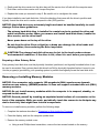
NOTICE: When taking the computer from low-temperature conditions into a
warmer environment or from high-temperature conditions into a cooler
environment, allow the computer to acclimate to room temperature before
turning on power.
When you disconnect a cable, pull on its connector or on its strain-relief loop, not on the cable itself. As
you pull out the connector, keep it evenly aligned to avoid bending any connector pins. Also, before you
connect a cable make sure both connectors are correctly oriented and aligned.
Handle components with care. Hold a component such as a memory module by its edges, not its pins.
When removing a memory module from the system board or disconnecting a peripheral device from the
computer, wait 5 seconds after turning off the computer before removing the memory module or
disconnecting the device to help avoid possible damage to the system board.
Clean the display with a soft, clean cloth and commercial window cleaner that does not contain wax or
abrasives. Apply the cleaner to the cloth; then stroke the cloth across the display in one direction,
moving from the top of the display to the bottom. If the display contains grease or some other
contaminant, use isopropyl alcohol instead of commercial window cleaner.
If your computer gets wet or is damaged, follow the procedures described in "Finding Solutions." If,
after following these procedures, you confirm that your computer is not operating properly, contact
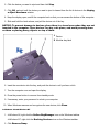
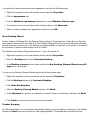
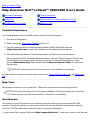
Dell. Ergonomic Computing Habits
CAUTION: Improper or prolonged keyboard use may result in injury.
CAUTION: Viewing the display or external monitor screen for extended periods of
time may result in eye strain.
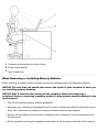
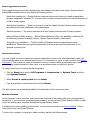
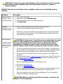
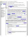
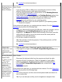
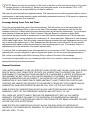
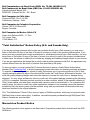
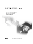
For comfort and efficiency, observe the following ergonomic guidelines when setting up and using your
computer:
Position your computer directly in front of you as you work.
Adjust the tilt of the computer's display, its contrast and/or brightness settings, and the lighting around
you (such as overhead lights, desk lamps, and the curtains or blinds on nearby windows) to minimize
reflections and glare on the display.
When using an external monitor with your computer, set the monitor at a comfortable viewing distance
(usually 510 to 610 millimeters [20 to 24 inches] from your eyes). Make sure the monitor screen is at
eye level or slightly lower when you are sitting in front of the monitor.
Use a chair that provides good lower-back support.
Keep your forearms horizontal with your wrists in a neutral, comfortable position while using the
keyboard, touch pad, track stick, or external mouse.
Always use the palmrest with the keyboard, touch pad, or track stick. Leave space to rest your hands
when using an external mouse.
Let your upper arms hang naturally at your sides.
Sit erect with your feet resting on the floor and your thighs level.
When sitting, make sure the weight of your legs is on your feet and not on the front of your chair seat.
Adjust your chair's height or use a footrest, if necessary, to maintain proper posture.
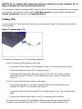
Vary your work activities. Try to organize your work so that you do not have to type for extended
periods of time. When you stop typing, try to do things that use both hands.
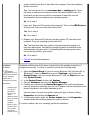
1 Computer positioned directly in front of user
2 Wrists relaxed and flat
3 Arms at desk level
When Removing or Installing Memory Modules
Before removing or installing memory modules, perform the following steps in the sequence indicated.
NOTICE: The only time you should ever access the inside of your computer is when you
are installing memory modules.
NOTICE: Wait 5 seconds after turning off the computer before disconnecting a
peripheral device or removing a memory module to help prevent possible damage to the
system board.
1. Turn off your computer and any attached peripherals.
2. Disconnect your computer and peripherals from AC power to reduce the potential for personal injury or
shock. Also, disconnect any telephone or telecommunication lines from the computer.
3. Remove the main battery from the battery compartment and, if necessary, the secondary battery from
the options bay.
4. Ground yourself by touching the unpainted metal surface of the I/O panel on the back of the computer.
While you work, periodically touch the I/O panel to dissipate any static electricity that might harm
internal components.
Protecting Against Electrostatic Discharge
Static electricity can harm electronic components inside your computer. To prevent static damage, discharge
static electricity from your body before you touch any of your computer's electronic components, such as a
memory module. You can do so by touching an unpainted metal surface on the computer's I/O panel.
As you continue to work inside the computer, periodically touch an I/O connector to remove any static charge
your body may have accumulated.
You can also take the following steps to prevent damage from electrostatic discharge (ESD):
When unpacking a static-sensitive component from its shipping carton, do not remove the component
from the antistatic packing material until you are ready to install the component. Just before
unwrapping the antistatic packaging, be sure to discharge static electricity from your body.
When transporting a sensitive component, first place it in an antistatic container or packaging.
Handle all sensitive components in a static-safe area. If possible, use antistatic floor pads and
workbench pads.
The following notice may appear throughout this document to remind you of these precautions:
NOTICE: See "Protecting Against Electrostatic Discharge" in the safety instructions at
the front of this guide.
Back to Contents Page
Back to Contents Page
Features and Options: Dell™ Latitude™ C600/C500 User's
Guide
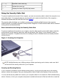
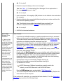
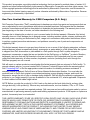
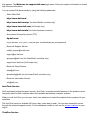
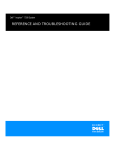
Figure 1, Figure 2, and Figure 3 show the front, back, and bottom views of the computer.
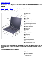
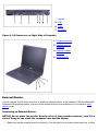
Figure 1. Front View of the Computer
1 Display latch
2 Display
3 Microphone
4 Air outlet
5 S-Video connector
6 Optional network connector
7 Optional modem connector
8 Audio jack (1)
9 System status lights
10 Infrared port
11 Speaker
12 Modular bay
13 Display latch button
14 Battery bay
15 Touch pad
16 Track stick
17 Keyboard status lights
18 Power button
19 Dell AccessDirect™ key
NOTICE: To avoid overheating the computer, do not place any objects close to the air
outlet or air vent, or allow any objects to cover up the outlet or air vent (see Figures 1
and 2).
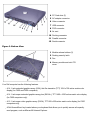
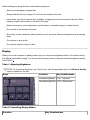
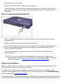
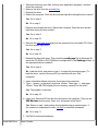
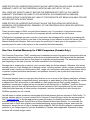
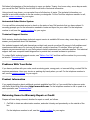
Figure 2. Back View of the Computer
1 Speaker
2 Security cable slot
3 Hard-disk drive
4 PC Card slots (2)
5 AC adapter connector
6 Video connector
7 USB connector
8 PS/2 connector
9 Air vent
10 Docking connector
11 Parallel connector
12 Serial connector
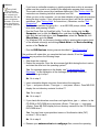
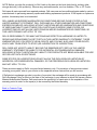
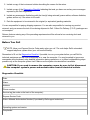
Figure 3. Bottom View
1 Module release latches (2)
2 Docking security latch
3 Fan
4 Memory module and mini-PCI
cover
Your Dell computer has the following features:
A 14.1-inch extended graphics array (XGA), thin film transistor (TFT) 1024 x 768 active-matrix color
display (for C600 and C500 computers).
A 14.1-inch super extended graphics array plus (SXGA+), TFT 1400 x 1050 active-matrix color display
(for C600 computers only).
A 12.1-inch super video graphics array (SVGA), TFT 800 x 600 active-matrix color display (for C500
computers only).
A Dell AccessDirect key located above your keyboard that allows you to quickly access a frequently
used program, such as Microsoft® Internet Explorer.
A CD-ROM drive that can be used in the modular bay. When you unpack your computer, look for the
CD-ROM drive in the accessories box of the shipping carton.
128-bit hardware-accelerated video support, with 8 megabytes (MB) of video memory. Support for a zoomed video (ZV) PC Card in the lower PC Card connector.
ESS Maestro 3i audio controller with software wavetable support and 3D surround sound.
Two audio jacks for connecting external speakers, headphones, or a microphone.
Integrated microphone and two stereo speakers.
Accelerated graphics port (AGP) architecture that increases the computer's video performance.
Energy efficiency. An ENERGY STAR® partner, Dell has determined that this product meets the
ENERGY STAR guidelines for energy efficiency.
A modular bay that supports modules such as a DVD-ROM drive, CD-ROM drive, CD-RW drive,
diskette drive, second battery, second hard-disk drive, Zip drive, or SuperDisk drive. To make the
computer as light as possible when you travel, use the travel module in the modular bay.
NOTE: Your computer was shipped with a diskette drive in the modular bay. For
information on removing the diskette drive and installing a different device in the bay, see
"Modular Bay."
Optional V.90 Mini PCI Modem data/fax modem, PC99-compliant, and ACPI power management
support (including remote wake-up for Windows® 2000).
For additional information on the Mini PCI Card modem, see "Connecting Devices" and the V.90 Mini
PCI Modem User's Guide.
Optional 10/100 LAN + V.90 Modem Mini PCI Card data/fax modem, PC99-compliant, and ACPI
power management support (including remote wake-up for Windows 2000).
For additional information on the Mini PCI Card modem, see "Connecting Devices" and the 10/100 LAN
+ V.90 Modem Mini PCI Card User's Guide.
A minimum of 64-MB synchronous dynamic random-access memory (SDRAM) module is standard.
You can increase memory up to 512 MB by installing combinations of 64-, 128-, or 256-MB 100megahertz (MHz) SDRAM modules in the two memory module sockets on the system board. Two power conservation modes—suspend mode and suspend-to-disk mode—that help you conserve
battery power. If the batteries run out of power, suspend-to-disk mode prevents data loss by copying
all system data to the hard-disk drive and turning off the computer.
Connectors for two 3.3-volt (V) or 5-V PC Cards. The lower PC Card connector supports ZV PC Cards.
NOTE: The PC Card controller supports the CardBus standard for 32-bit data transfer on
the PC Card.
Hardware and software support for the Dell Latitude C/Port Family Advanced Port Replicator (APR)
and the Dell Latitude C/Dock Family Expansion Station.
A Dell DualPoint integrated pointing device which includes both a touch pad and a track stick. These
pointing devices are positioned for both left- and right-handed users. The track stick is positioned in the
keyboard to allow you to move the cursor while keeping your fingers in a typing position. Two sets of
left and right buttons, located above and below the touch pad, mimic mouse buttons. You can also
perform many pointing functions by tapping the touch pad or the track stick. Click-and-drag buttonless
functions are also supported.
An 8-cell, 59 watt-hour (WH) lithium ion battery (standard) in the battery bay, with support for a second
battery in the modular bay. For lithium ion batteries, the Dell ExpressCharge™ technology charges a
single battery in approximately 1 hour when the computer is off or in suspend mode. Optional 4-cell, 26.5-WH lightweight lithium ion battery. CAUTION: Do not puncture, disassemble, or incinerate the computer's battery.
The battery may present a fire or chemical burn hazard if mistreated. Do not
expose the battery to temperatures above 60° Celsius (C) (140° Fahrenheit [F]).
Keep the battery away from children. Handle damaged or leaking batteries with
extreme care; electrolyte may leak from the cells and cause personal injury.
CAUTION: If your battery is damaged, or if it no longer holds a charge, dispose of
it promptly and properly. Do not dispose of it along with household waste. Call
your local waste disposal agency or environmental agency for advice on
disposing of the battery. CAUTION: Using the wrong battery type may present a risk of fire or explosion.
Replace the battery only with the same or equivalent type purchased from Dell.
You can use your computer's battery in any Latitude C-Family computer except for
the Latitude CS or CSx computers. Do not attempt to use the battery in CS or CSx
computers, and do not use a battery from those computers in your computer.
High-performance parallel and serial ports and a multipurpose Personal System/2 (PS/2) connector for
attaching external devices, a monitor connector for attaching an external monitor to your computer, and
a Universal Serial Bus (USB) connector that supports stand-alone and hub devices.
An infrared port that permits file transfer without the use of cable connections. The port is compatible
with the Infrared Data Association (IrDA) Standard 1.1 (Fast IR) and Standard 1.0 (Slow IR) for use
with external devices.
Dell HyperCool™, an automatic thermal management system that uses a variable-speed fan,
microprocessor speed changes, and Intel® Remote Heat Exchanger technology to keep the computer
running at the optimum temperature.
The following software is included with your Dell computer:
The Intel® SpeedStep™ technology is installed on your hard-disk drive.
The Windows operating system that you ordered with your computer.
The system setup program lets you view and change the system configuration. For more information,
see "Using the System Setup Program."
Dell Diagnostics for evaluating the computer's components and devices.
NOTE: If Dell did not install an operating system on your hard-disk drive, the drivers, system utilities,
and diagnostics are available separately from Dell. To order them, see "Getting Help" for the
appropriate telephone number in your location.
Available Options
For information on the available options for your computer, visit the Dell Web site at
http://www.dell.com. Back to Contents Page
Back to Contents Page
Using Your Computer: Dell™ Latitude™ C600/C500 User's
Guide
Turning the Computer On and Off
Keyboard and Keypad Controls
Modular Bay
Dell AccessDirect™ Key
Diskette Drive
Speaker Controls
Removable Mass-Storage Drives
Controlling the Cursor
Display
PC Cards
Turning the Computer On and Off
To turn on the computer, press the power button. (See Figure 1 in "Features and Options.")
To turn off the computer, follow the standard shutdown procedure described in your operating system
documentation.
CAUTION: Do not allow your Latitude portable computer to operate for an
extended period of time with the base resting directly on your body. With
extended operation, heat can potentially build up in the base. Allowing sustained
contact with the skin could cause discomfort or, eventually, a burn. Modular Bay
Your computer comes with a diskette drive installed in the modular bay. To use another device in the
modular bay, first remove the diskette drive.
NOTICE: When drives are not inside the computer, they are fragile and must be handled
carefully to avoid damage. Do not press down on the drives or place heavy objects on
top of them. Place the drives in a travel case to keep them free of dust and liquids.
Store the drives in a safe place.
NOTICE: If the computer is docked, turn off the computer and undock it before
installing or removing a drive.
You can install the following modules in the modular bay:
Second battery
CD-ROM drive
DVD-ROM drive
CD-RW drive
SuperDisk drive
Zip drive
Second hard-disk drive
To make the computer as light as possible, use the travel module in the modular bay in place of any of the
available drives.
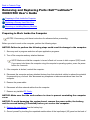
Swapping Devices While the Computer Is Off
1. Save and close any open files, exit any open programs, and shut down the computer.
2. If the computer is connected (docked) to an Advanced Port Replicator (APR) or docking station,
undock it.
3. Close the display and turn the computer over.
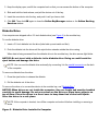
4. Slide and hold the latch release, and pull the device out of the bay.
NOTICE: To prevent damage to devices, place them in a travel case when they are not
inserted in the computer. Store devices in a dry, safe place, and avoid pressing down
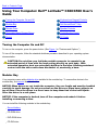
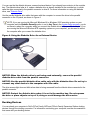
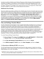
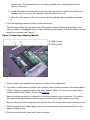
on them or placing heavy objects on top of them. 1 Device
2 Modular bay latch
NOTICE: Insert devices before you dock and turn on the computer. 5. Insert the new device into the bay, and push it until you hear a click.
6. Turn the computer over and open the display.
7. Turn on the computer.
Swapping Devices While the Microsoft® Windows® Operating System Is Running
NOTICE: To prevent damage to the docking connector, do not remove or replace
devices while the computer is connected to an APR or docking station. In Windows XP
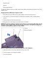
1. Double-click the
icon on the Windows taskbar.
2. Click the device you want to eject.
3. Keep the display open, and tilt the computer back so that you can access the bottom of the computer.
4. Slide and hold the latch release, and pull the device out of the bay.
NOTICE: To prevent damage to devices, place them in a travel case when they are not
inserted in the computer. Store devices in a dry, safe place, and avoid pressing down
on them or placing heavy objects on top of them. 1 Device
2 Modular bay latch
5. Insert the new device into the bay, and push the device in until you hear a click.
6. If necessary, enter your password to unlock your computer.
In Windows 2000
1. Double-click the
icon on the Windows taskbar.
2. Click the device you want to eject and then click Stop.
3. Click OK, and wait until the device you want to eject is cleared from the list of devices in the Unplug
or Eject Hardware window.
4. Keep the display open, and tilt the computer back so that you can access the bottom of the computer.
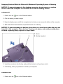
5. Slide and hold the latch release, and pull the device out of the bay.
NOTICE: To prevent damage to devices, place them in a travel case when they are not
inserted in the computer. Store devices in a dry, safe place, and avoid pressing down
on them or placing heavy objects on top of them. 1 Device
2 Modular bay latch
6. Insert the new device into the bay, and push the device in until you hear a click.
7. Turn the computer over and open the display.
8. Press the power button to resume from standby mode.
9. If necessary, enter your password to unlock your computer.
10. When Windows resumes and recognizes the new device, click Close.
In Windows 98 and Windows NT 1. In Windows 98, right-click the Softex BayManager icon on the Windows taskbar.
In Windows NT, right-click the Docking Services icon on the Windows taskbar.
2. Click Remove/Swap.
3. Keep the display open, and tilt the computer back so that you can access the bottom of the computer.
4. Slide and hold the latch release, and pull the device out of the bay.
5. Insert the new device into the bay, and push it until you hear a click.
6. Click OK. Then click OK again to close the Softex BayManager window or the Softex Docking
Services window.
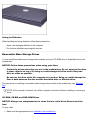
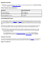
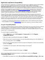
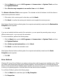
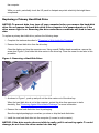
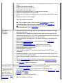
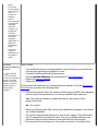
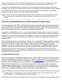
Diskette Drive
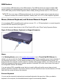
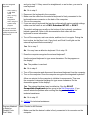
Your computer was shipped with a 3.5-inch diskette drive (see Figure 2) in the modular bay. To use the diskette drive:
1. Insert a 3.5-inch diskette into the drive (label side up and metal end first). 2. Push the diskette into the drive until the eject button extends outside the drive casing.
When data is being accessed from the diskette drive in the modular bay, the drive access light blinks.
NOTICE: Do not travel with a diskette in the diskette drive. Doing so could break the
eject button and damage the drive.
NOTE: You can use the diskette drive externally by connecting it to the parallel connector on the back
of the computer.
To remove a diskette from the drive:
1. Press the eject button to release the diskette.
2. Pull the diskette out of the drive.
To remove the drive or to use another device in the modular bay, see "Modular Bay."
NOTICE: When drives are not inside the computer, they are fragile and must be handled
carefully to avoid damage. Do not press down on the drives or place heavy objects on
top of them. Place the drives in a travel case to keep them free of dust and liquids.
Store the drives in a safe place.
NOTE: If the computer is docked, turn off the computer and undock it before installing or removing a
drive.
Figure 2. Diskette Drive Installed in Computer
Caring for Diskettes
When handling and using diskettes, follow these precautions:
Never use damaged diskettes in the computer
Do not store diskettes near magnetic sources
Removable Mass-Storage Drives
You can install removable-mass storage drive modules such as a CD-ROM drive or SuperDisk drive in the
modular bay. NOTICE: Follow these precautions when using your drive:
Protect the drives when they are not in the modular bay. Do not squeeze the drive
or place objects on top of it; doing so could damage the drive motor. Keep the
drive as clean as possible.
Do not use the drive while the computer is in motion. Doing so could interrupt the
flow of data between the disc and the hard-disk drive or diskette drive.
For instructions on installing a removable mass-storage drive module in the modular bay, see "Modular
Bay." NOTE: If the computer is docked, turn off the computer and undock it before installing or removing a
drive.
CD-ROM, CD-RW, and DVD-ROM Drives
NOTICE: Always use compressed air to clean the lens in the drive. Never touch the
lens.
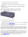
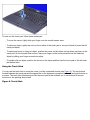
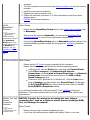
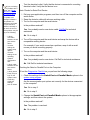
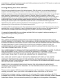
To play a disc:
1. Make sure the appropriate drive is installed in the modular bay.
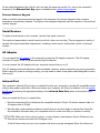
2. Press the eject button on the front of the drive or press <Fn><F10>. 3. When the tray slides out, place the disc into the tray label side up.
Make sure that the CD is seated correctly on the spindle by pressing down on the disc until it
clicks in place. NOTICE: If the disc is not seated correctly, the drive or media can be damaged.
4. Gently push in the tray.
When the drive is in use, the drive access light blinks on the computer’s front panel.
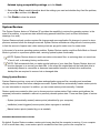
Figure 3. DVD-ROM, CD-ROM, or CD-RW Drive Installed in Computer
To eject the drive tray, perform one of the following tasks:
press the eject button on the front of the drive
press <Fn><F10> (on an external keyboard, press <Scroll Lock> instead of <Fn> if the External Hot
Key option is enabled in the system setup program)
You can only use CD-ROM, DVD-ROM, and CD-RW drives externally with a C/Port Family Advanced Port
Replicator (APR) or a C/Dock Family Expansion Station. If you are using the Microsoft Windows 98 operating system, disable the autoplay (auto insert notification)
feature while you use the drive. (The autoplay feature can interfere with the computer’s power management
functions.) If Dell installed the operating system, the autoplay feature has been disabled. If you reinstall the
operating system or if you installed it yourself, be sure to disable the autoplay feature if you want to use the
drive. For instructions on changing the Auto Insert Notification option, see the operating system user’s guide.
DVD-ROM and CD-ROM drives are read-only devices that let you play most sound and video CDs. DVDROM drives can also play DVDs. CD-rewritable (CD-RW) drives can write to and play CD-recordables (CDR) or CD-RWs and can play CDs. Dell has installed the appropriate device drivers on your hard-disk
drive. See "Technical Specifications" for information on supported CD and DVD formats.
Caring for Discs
When handling and using the discs, follow these precautions:
Never use a damaged or warped disc.
Always hold the disc by its edges. Do not touch the surface of the disc.
Use a clean, dry cloth to remove dust, smudges, or fingerprints from the surface of the disc. When
cleaning, wipe from the center of the disc to the edge.
Never use solvents, such as benzene, record cleaners, or antistatic sprays, to clean the disc.
Do not write on the surface of the disc.
Store discs in their containers, placing them in a cool, dry place. Extreme temperatures may damage
discs.
Do not bend or drop a disc.
Do not place objects on top of a disc.
Display
When you run the computer on battery power, set your computer's brightness control to the lowest setting
that affords comfortable viewing. You can conserve battery power by using the minimum brightness setting
(see Table 1) 1 .
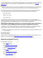
Table 1. Adjusting Brightness
NOTE: On an external keyboard, use <Scroll Lock> with the appropriate keys if the External Hot Key
option is enabled in the ddd.
Keys
Function
Key Combinations
Increase brightness
<Fn> + up arrow
Decrease brightness <Fn> + down arrow
Table 2. Controlling Display Modes
Function
Key Combinations
Switch the computer’s display between expanded
mode and regular video mode.
<Fn><F7>
Switch the video image to the next display in the
following sequence: the computer's display, an
external monitor, or both displays simultaneously. <Fn><F8>
Turn off the display. This key combination applies
only to Windows 98, and Windows NT and may not
be supported under certain conditions. 2
<Fn><d>
1 You
cannot adjust contrast on your display.
2
Certain key combinations may not function with the Advanced Configuration and Power Interface (ACPI)
or may require configuration with the Power Management Properties window in the Control Panel. See
"Power Management and Conservation."
Expanded Video Mode
When working in text mode, you can select the font used to display text. Press <Fn><F7> to toggle between
a regular serif font and a serif font with extra leading. Expanded video mode is useful if you are working in
800 x 600 resolution on a 14.1-inch XGA display.
Customizing Display Resolution
In Windows XP
1. Click the Start button, and then click Control Panel.
2. Under Pick a category, click Appearance and Themes.
3. Under Pick a task..., click the area you want to change, or under or pick a Control Panel icon,
click Display.
4. Try different settings for Color Quality and Screen resolution.
In Windows 2000, Windows 98, and Windows NT
1. Click the Start button, point to Settings, and then click Control Panel.
2. Double-click the Display icon, and then click the Settings tab.
3. Try different settings for Colors and Screen area. For more information, see your operating system documentation.
If you choose a resolution or color palette that is higher than the display supports, the settings adjust
automatically to the closest possible setting.
Video Drivers and Video Resolution The Dell-installed video drivers work with the operating system to let you customize the video resolution and
number of screen colors on your display. For detailed information on video resolution, see "Technical
Specifications."
NOTE: The Dell-installed video drivers are designed to offer the best performance on your computer.
Dell recommends that you use only these drivers with your factory-installed operating system.
If the video resolution setting is higher than what the display supports, the computer display enters pan
mode. The computer enters pan mode at the following resolutions (depending on display type):
XGA: 1280 x 1024
SXGA+: 1400 x 1050
UGA: 1600 x 1200
In pan mode the screen resolution is too high to be completely displayed on the computer display. For
example, the taskbar that usually appears at the bottom of the desktop may no longer be visible. To view the
rest of the screen, use the touch pad or track stick to pan up and down and left and right. NOTICE: Before adjusting the refresh rate on an external monitor, refer to the monitor's
user's guide. You can damage the monitor by using an unsupported refresh rate.
To display more colors, select a lower resolution. If you select a resolution and color combination that the
system does not support, the system automatically selects the next supported combination.
NOTE: Color depth is based on 256 colors for 8-bit, 65,536 colors for 16-bit, and 4,294,967,296 colors
for 32-bit displays. Dual-Display Mode
With the Microsoft Windows 98 operating system, you can use an external monitor as an extension of your
display. For more information, see "Using an External Monitor in Dual-Display Mode." Keyboard and Keypad Controls Key combinations allow you to:
Control display settings
Eject removable mass-storage drives
Control the Dell AccessDirect™ key
Adjust speaker volume
Use the embedded numeric keypad
Enter power management modes
Enter the system setup program
NOTE: On an external keyboard, use <Scroll Lock> with the appropriate keys if the External Hot Key
option is enabled in the system setup program.
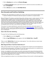
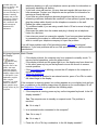
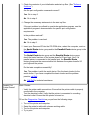
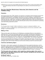
Embedded Numeric Keypad
To activate the keypad, press <Num Lk>. The Num Lock light turns on.
Figure 4. Embedded Numeric Keypad
As you work, you may want to use the embedded numeric keypad (see Figure 4) to enter numbers in
spreadsheet or financial programs. The keypad shares some of the keys on your computer's keyboard. The
number and symbol characters are marked to the right on these keys. Table 3. Embedded Numeric Keypad Key Combinations
Function
When Keypad Is On
Turn off the keypad
<Num Lk>
Temporarily enable the lowercase
characters/functions of the keyboard
<Fn><key>
Temporarily enables the uppercase
characters/functions of the keyboard
<Fn><Shift><key>
Temporarily enable a cursor-control key in the
keypad
<Shift><cursor key>
Function
When Keypad Is Off
Turn on the keypad
<Num Lk>
Temporarily enable a cursor-control key in the
keypad
<Fn><cursor key>
Temporarily enable a number or symbol key in the
keypad
<Fn><Shift><number key>
Table 4. Power Conservation Key Combinations
Function
Key Combinations
Turn off the display*
<Fn><d> Turn off the hard-disk drive*
<Fn><h>
Activate suspend, sleep, or standby mode*
<Fn><Esc>
Activate suspend-to-disk mode*
<Fn><a> or
<Fn><q> on French keyboards
* This key combination does not function with ACPI if the settings have not been configured with the Power
Management Properties window in the Control Panel. See " Power Management and Conservation."
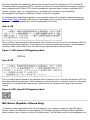
Table 5. System Setup Program Key Combinations
Function
Key Combinations
Open the system setup program
<Fn><F1>*
Open the Battery Status screen of the system
setup program
<Fn><F3>*
* This key combination does not function with ACPI.
Dell AccessDirect Key The Dell AccessDirect key located above your keyboard allows you to quickly access a frequently used
program, such as Microsoft Internet Explorer (see Figure 1 in "Features and Options").
NOTE: Using an external keyboard with your computer disables the AccessDirect key.
For information on using an AccessDirect key and viewing or changing key assignments, see the
AccessDirect Help:
1. Open the Dell AccessDirect program in one of the following ways:
Double-click the AccessDirect icon in the system tray on the Windows taskbar (normally in the
bottom-right corner of the screen).
For Windows XP, click the Start button and click Control Panel. In the Control Panel
window, click Printers and Other Hardware. Click the Keyboard icon, and then click the
AccessDirect tab.
For Windows 98 and Windows 2000, click the Start button, point to Settings, and then click
Control Panel. In the Control Panel window, double-click the Keyboard icon, and then
click the AccessDirect tab.
2. Click Help.
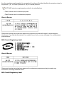
Speaker Controls
NOTE: On an external keyboard, use <Scroll Lock> with the appropriate keys if the External Hot Key
option is enabled in the system setup program.
Table 6. Speaker Key Combinations
Function
Key Combinations
Turn the volume up
<Fn><Page Up>
Turn the volume down
<Fn><Page Dn>
Turn the speakers on or off
<Fn><End>
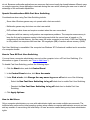
Controlling the Cursor
Your Dell portable computer is equipped with the Dell DualPoint integrated pointing device, which includes
two cursor pointing devices (see Figure 5 and Figure 6) that perform traditional mouse functions: the touch
pad and the track stick. You can choose to use the touch pad only, the track stick only, or both at the same
time. DualPoint device software allows you to set the default for the type of cursor pointing device you want to
use, as well as sensitivity, motion, and drag and drop features of both the touch pad and track stick. NOTES: When enabled, the DualPoint device (whether touch pad only, track stick only, or both)
uses interrupt request (IRQ) 12. No other device can use IRQ12 while the DualPoint integrated
pointing device is enabled.
If the Pointing Device option in the system setup program is set to Touch Pad-PS/2 Mouse
(the default), you can use both the DualPoint device and an external mouse if one is attached.
Using the Touch Pad
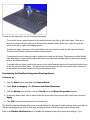
You can use the touch pad to move the cursor, just like a standard mouse (see Figure 5). The touch pad’s
two buttons, located directly below the touch pad, correspond to the left and right buttons on a mouse.
Figure 5. Touch Pad
To best use the touch pad, follow these techniques:
To move the cursor, lightly slide your finger over the smooth sensor area.
To select an object, gently tap once on the surface of the touch pad or use your thumb to press the left
touch pad button. To select and move (or drag) an object, position the cursor on the object and tap down-up-down on the
touch pad. On the second down motion, leave your finger on the touch pad and move the selected
object by sliding your finger across the surface.
To double-click an object, position the cursor on the object and then tap the touch pad or the left touch
pad button twice.
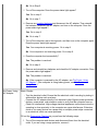
Using the Track Stick
You can use the track stick to move the cursor, just like a standard mouse (see Figure 6). The two buttons
located between the touch pad and the space bar on the keyboard correspond to the left and right buttons on
a mouse. The track stick functions much like the touch pad in that it allows you to use buttons for mouse
functions or the pointing device itself. Figure 6. Track Stick
To best use the track stick, use the following techniques:
To move the cursor, apply pressure to the track stick with your right or left index finger. Press up or
down to move the cursor to the top or bottom of the display screen. Press left or right to move the
cursor to the left or right of the display screen.
To select an object, tap once on the track stick or use your thumb to press the left track stick button. The track stick buttons perform standard mouse functions.
To select and move (or drag) an object, position the cursor on the object. Then press and hold the left
track stick button. Leave your thumb on the button and move the selected object by pressing the track
stick in the desired direction.
To double-click an object, position the cursor on the object and then tap the left track stick button twice
or tap the track stick itself twice. The track stick functions much like the touch pad in that it allows you
to use buttons for mouse functions or the pointing device itself. Customizing the DualPoint Integrated Pointing Device
In Windows XP
1. Click the Start button, and then click Control Panel.
2. Under Pick a category, click Printers and Other Hardware. 3. Click the Mouse icon, and then click the Touch tab in the Mouse Properties window.
4. In the drop-down menu, click to select either the touch pad or the pointing stick (track stick) and click
Apply.
5. Click OK to save the settings and close the window.
The DualPoint device software allows you to set the default for the type of cursor pointing device you want to
use, as well as sensitivity, motion, and drag and drop features of both the touch pad the track stick.
Click in the Disable this Device box to disable the selected touch pad or track stick settings. If you
docked your computer with a mouse, the touch pad and track stick settings are automatically disabled.
In Windows 2000, Windows 98, and Windows NT
1. Click the Start button, point to Settings, and then click Control Panel.
2. Double-click the Mouse icon and click the Touch tab in the Mouse Properties window.
3. In the drop-down menu, click to select either the touch pad or the pointing stick (track stick) and click
Apply.
4. Click OK to save the settings and close the window.
To open the Mouse Properties window, you can also right-click the Touch Pad icon on the taskbar, and
click Touch Pad Properties.
To disable the selected touch pad or track stick settings, click in the Disable this Device box. If you
docked your computer with a mouse, the touch pad and track stick settings are automatically disabled.
The DualPoint device software allows you to set the default for the type of cursor pointing device you want to
use, as well as sensitivity, motion, and drag and drop features of both the touch pad and track stick. Click in the Disable this Device box to disable the selected touch pad or track stick settings. If your
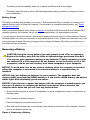
computer is docked with a mouse, the touch pad and track stick settings are automatically disabled. Changing the Track Stick Cap
1. Pull the cap off the track stick (see Figure 7).
Figure 7. Removing the Track Stick Cap
2. Align a new cap over the square track stick post and gently press the cap down onto the post. 3. Test the track stick to ensure that the cap is seated properly.
Your computer came with four additional track stick caps in assorted colors. You may need to change the
track stick cap if it wears down from prolonged use.
PC Cards
The computer has a slot into which you can install up to two PC Cards if the PC Cards comply with Release
2.01 of the Personal Computer Memory Card International Association (PCMCIA) standard and Release 4.2
of the Japanese Electronic Industry Development Association (JEIDA) standard. See "Technical
Specifications" for information on supported PC Cards.
NOTES: A PC Card is not a boot device. The "type" of a card refers to its thickness, not its
functionality.
Your computer recognizes most I/O cards and automatically loads the device driver associated with
that card.
NOTICE: Extended cards are longer versions of standard PC Cards. They fit into and
operate correctly with your computer. Follow these precautions when using extended
PC Cards:
Make sure that nothing strikes the exposed end of an installed extended card.
Otherwise, damage to the system board can occur. Always remove an extended PC Card before you pack the computer in its carrying
case.
Try installing an extended card in the upper PC Card connector to allow room for a
second PC Card.
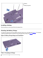
Installing PC Cards
1. Stop the card process with the PC Card configuration utility on the task bar.
You do not need to turn off your computer or exit suspend or standby mode before you install a
PC Card. 2. If necessary, remove the blank from the PC Card connector you intend to use (see "Removing PC
Cards or Blanks").
3. Hold the card with its orientation symbol pointing into the slot and the top side of the card facing up.
4. Insert the card into the slot, press in firmly until the card is completely seated in the internal PC Card
connector (see Figure 8), and rotate the PC Card eject button to its original position.
PC Cards are generally marked with a symbol, such as a triangle or an arrow, to indicate which
end should be inserted into the slot. The cards are keyed to prevent incorrect insertion. If card
orientation is not clear, see the documentation that came with the card.
Figure 8. Installing a PC Card
5. If you encounter resistance when inserting it, do not force the card. Check the card's orientation and try
again.
NOTE: Use a ZV PC Card in the lower connector only.
PC Card Blanks
Save the blank to use whenever you do not have a PC Card installed. The blank protects the PC Card
connector from dust and other particles.
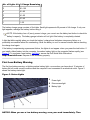
Removing PC Cards and Blanks
NOTICE: If you are using Windows 98 or Windows 2000, use the PC Card configuration
utility on the taskbar to select and stop a card before you remove it. If you do not stop
the card using the configuration utility, you could lose data from open application
programs.
1. Stop the PC Card by using the PC Card configuration utility on the taskbar.
2. Rotate the PC Card eject button outward (see step 1 in Figure 9) for the card or blank you want to
eject.
Figure 9. Removing a PC Card
3. Press the PC Card eject button (see step 2 in Figure 9).
The PC Card or blank protrudes from the slot slightly. It does not come out all the way.
4. Gently remove the card or blank (see step 3 in Figure 9), and rotate the PC Card eject button to its
original position.
Configuring PC Cards
The PC Card configuration utility performs the following functions:
Notifies you whenever a PC Card is inserted and tells you how the card is configured
Automatically loads the proper device driver if it is available on the hard-disk drive
If drivers are not available on the hard-disk drive, prompts you to install them using the device driver
CD that came with the card
The operating system automatically detects a PC Card and opens the Add New Hardware menu from
the Control Panel. For information, see the PC Card operating system documentation.
Back to Contents Page
Back to Contents Page
Connecting Devices: Dell™ Latitude™ C600/C500 User's
Guide
About the I/O Connectors
AC Adapter
External Monitor
Infrared Port
Parallel Devices
Modem
Docking Devices
Network
USB Devices
S-Video (Television)
Mouse, External Keyboard, and External
Numeric Keypad
Audio Devices
Serial Devices
About the I/O Connectors
You can connect external devices to the input/output (I/O) connectors. The computer's basic input/output
system (BIOS) detects the presence of external devices when you boot (start) or reboot your computer.
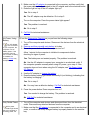
Figure 1 shows the I/O connectors on the back of your computer; Figure 2 shows the modem, TV, and audio
connectors on the side of the computer.
NOTES: Some external devices require you to load software called device drivers into system
memory before the devices will work. These device drivers help your computer recognize the external
device and direct its operation. Instructions for installing this software are usually included in the
upgrade kits.
For instructions on using the I/O connectors on the C/Port Family Advanced Port Replicator (APR) or
C/Dock Family Expansion Station, see the documentation that came with that device.
NOTICE: When disconnecting external devices from the back of the computer, wait 5
seconds after turning off the computer before you disconnect a device to avoid
possible damage to the system board.
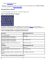
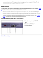
Figure 1. I/O Connectors on Back of Computer
1 Serial
2 Parallel
3 Docking
4 PS/2 connector (for mouse, keyboard, or
keypad)
5 USB
6 Video
7 AC power
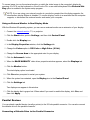
Figure 2. I/O Connectors on Right Side of Computer
1 S-Video connector
2 Optional network
connector
3 Optional modem
connector
4 Audio jacks (2)
External Monitor
You can use the 15-hole video connector to attach an external monitor to the computer. With the Microsoft®
Windows® 98 operating system, you can use an external monitor as an extension of your display in dualdisplay mode. Connecting an External Monitor
NOTICE: Do not place the monitor directly on top of your portable computer, even if it is
closed. Doing so can crack the computer case and the display.
1. Make sure that the external monitor is turned off. Set the monitor on a monitor stand, desk top, or other
level surface near your computer.
2. Connect the external monitor's video cable to the computer.
Plug the video cable connector into the matching video connector on the back of the computer,
as shown in Figure 3. If the video cable is not permanently attached to the monitor, connect it to
the monitor.
Figure 3. Connecting an External Monitor
Be sure to tighten all the screws on the video cable connector(s) to eliminate radio frequency
interference (RFI).
3. Connect your external monitor to a grounded electrical outlet.
Plug the three-prong connector on one end of the monitor's power cable into a grounded power
strip or some other grounded power source. If the cable is not permanently attached to the
monitor, connect it to the monitor.
You can also connect an external monitor to the C/Port Family APR or the C/Dock Family
Expansion Station.
NOTE: If you are using the Microsoft Windows 98 operating system, you can use an
external monitor as an extension of your display. For more information, see your operating
system documentation or "Using an External Monitor in Dual-Display Mode." Using an External Monitor
When an external monitor is connected to the computer, the video image automatically appears on the
external monitor's screen when you boot your computer.
To toggle the video image between the display, an external monitor, or both simultaneously, press
<Fn><F8> on the keyboard. Press <Scroll Lock><F8> on an external keyboard if the External Hot Key
option is enabled in the system setup program.
If the external monitor is turned off when you boot your computer, the computer still sends the video image to
the external monitor, but you will not see an image on either the computer's display or the external monitor.
To see an image, turn on the external monitor or switch the video image to the computer’s display by
pressing <Fn><F8> on the keyboard or <Scroll Lock><F8> on an external keyboard if the External Hot
Key option is enabled in the system setup program.
NOTE: If you are using your external monitor at a resolution greater than the display supports, the
simultaneous display feature is disabled. To use the display, switch to a resolution that the computer
supports, or disconnect the external monitor and restart your computer.
Using an External Monitor in Dual-Display Mode
With the Windows 98 operating system, you can use an external monitor as an extension of your display. 1. Connect the external monitor, TV, or projector.
2. Click the Start button, point to Settings, and then click Control Panel.
3. Double-click the Display icon.
4. In the Display Properties window, click the Settings tab.
5. Change the Colors option to 256 Color or High Color (16 bit).
6. Change the Screen Area to the appropriate size for your display.
7. Click the Advanced... button.
8. When the RAGE MOBILITY video driver properties window appears, select the Displays tab.
9. Click the Monitor button. The dual-display option is activated.
10. Click Yes when prompted to restart your system.
11. When the system has restarted, open the Display icon in the Control Panel.
12. Click the Settings tab.
Two displays now appear in this window.
13. Click the display that is grayed out. When asked if you want to enable this display, click Yes, and
then click Apply.
Parallel Devices
You can attach a parallel device (usually a printer) to the 25-hole parallel connector. You can also connect
the diskette drive to the parallel connector.
Connecting a Diskette Drive to the Parallel Connector
You can use the the diskette drive as a second external device if you already have a device in the modular
bay. The diskette drive letter is A, unless a diskette drive is already installed in the modular bay, in which
case the drive connected to the parallel connector is drive B. For more information on using the diskette
drive, see "Diskette Drive."
Use the parallel diskette drive cable that came with the computer to connect the drive to the parallel
connector on the I/O panel, as shown in Figure 4.
NOTE: If you are running the Microsoft Windows 98 or Windows 2000 operating system on your
computer and the Diskette Reconfig option is set to Any Time in the system setup program, you do
not have to reboot the computer when you connect the diskette drive to the parallel connector. If you
are running the Microsoft Windows NT® operating system on your computer, you do need to reboot
the computer after you connect the diskette drive.
Figure 4. Using the Diskette Drive As an External Device
NOTICE: When the diskette drive is not being used externally, remove the parallel
diskette-drive cable from the parallel connector.
NOTICE: Use the parallel diskette-drive cable only with the diskette drive. Do not try to
connect any other device to the computer with this cable.
The drive access light does not blink when data is being accessed from the diskette drive connected to the
parallel connector.
NOTICE: Protect the diskette drive when it is not in the modular bay. Do not squeeze
the drive or place objects on top of it; doing so could damage the drive motor.
Docking Devices
You can attach your computer to Dell's C/Port Family APR and C/Dock Family Expansion Station docking
devices through the docking connector. For information on docking your computer, see the documentation
that came with your docking device.
USB Devices
You can attach a USB hub device to the USB connector. The USB hub device can support multiple USB
devices (typically low-speed peripherals such as mice, keyboards, printers, and computer speakers). The
C/Port APR Family and the C/Dock Expansion Station Family docking solutions have two USB connectors.
NOTE: If you are using a USB external keyboard, do not enter the system setup program by using a
keyboard command on an external keyboard. Instead, press <Fn><F1> on the computer's keyboard.
Mouse, External Keyboard, and External Numeric Keypad
You can attach a PS/2-compatible device such as a mouse, 101- or 102-key keyboard, or numeric keypad to
the mini-DIN PS/2 connector (see Figure 5).
You can also connect these devices to the C/Port Family APR or the C/Dock Family Expansion Station.
Figure 5. External Mouse, Keyboard, or Keypad Connector
Mouse
If the Pointing Device option in the system setup program is set to Touch Pad-PS/2 Mouse (the
default), you can use both the DualPoint device and an external PS/2-compatible mouse if one is attached. If
you disconnect the mouse, to use the advanced features of the DualPoint integrated pointing device, you
must shut down the computer or enter suspend or standby mode and then resume. If you do not do this, the
DualPoint integrated pointing device resumes operation in standard PS/2 mode, which means that many of
the configuration features are disabled.
If you are using a PS/2-compatible mouse that is not made by Microsoft and the mouse does not work
properly, reboot the computer. If the mouse still does not work, install the drivers from the diskette or CD that
came with the mouse and reboot the computer.
External Keyboard
You can use the computer's keyboard and an external keyboard at the same time. When you attach a
keyboard to the computer, the embedded numeric keypad is automatically disabled.
On an external keyboard, the <Scroll Lock> key acts the same way as the <Fn> key on the computer’s
keyboard (if the External Hot Key option is enabled in the system setup program).
External Numeric Keypad
When you attach an external numeric keypad to the computer, the numeric keypad on the computer
keyboard is automatically disabled. The lights on the integrated keyboard track the operation of an external
numeric keypad.
Serial Devices
To attach a serial device to the computer, use the 9-pin serial connector.
The serial port passes data in serial format (one bit at a time over one line). This port supports a variety of
devices that require serial data transmission, including a serial mouse, serial printer, plotter, or external
modem.
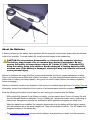
AC Adapter
You can attach the AC adapter to the computer by using the AC adapter connector. The AC adapter
converts AC power to the DC power required by the computer.
You can connect the AC adapter with your computer turned either on or off.
The AC adapter works with electrical outlets worldwide. However, power connectors vary among countries.
Before using AC power in a foreign country, you may need to obtain a new power cable designed for use in
that country.
Infrared Port
The computer’s infrared (IR) port lets you transfer files from your computer to another IR-compatible device
without using cable connections. When you receive your computer, the IR port is disabled. You can enable
the IR port by selecting the appropriate setting for the Infrared Data Port option in the system setup
program.
After you enable the IR port, to transfer files:
1. Point the computer’s IR port directly at the compatible device’s IR port. IR devices transmit data in a
30-degree cone of IR light. 2. Start the data communications software on both devices, and then begin to transfer files. Read the
documentation that came with your compatible device to make sure that you operate it correctly.
NOTES: Make sure that no books, papers, or other objects come between the two IR devices and
that the two devices are within the 30-degree cone.
If the IR device does not work, the computer and device may be misaligned. Move the device and
computer to bring them into the 30-degree cone.
The Microsoft Windows NT 4.0 operating system does not support the use of IR devices.
The IR port is compatible with Infrared Data Association (IrDA) 1.1 (Fast IR) and 1.0 (Slow IR) standards. An
IR data stream is transmitted through a lens in the computer up to a distance of 1 meter (m) (3.3 feet [ft]).
This light is received by a compatible computer, printer, mouse, or remote control.
The default address of the IR port is COM3. To avoid resource conflicts with other devices, remap the
address of the IR port.
When the computer is docked with the C/Port APR Family or C/Dock Expansion Station Family docking
solution, the IR port on the computer is automatically disabled.
For more information about using an IR device, see the documentation that came with your operating
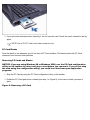
system. Modem
You can connect a telephone line to the optional modem through the modem connector on the right side of
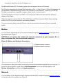
the computer (see Figure 6). NOTICE: Do not confuse the modem and network connectors on your computer. Do not
plug a telephone line into the network connector.
Figure 6. Modem and Network Connectors
1 Optional modem connector
2 Optional network connector
For information on using the modem, see the online modem documentation supplied with your computer. To
access this documentation, double-click the Dell Documents icon on the Windows desktop, click
System Information, and then click Communications. Network
You can connect to the integrated network interface controller (NIC) through the optional network connector
on the right side of the computer (see Figure 6).
NOTICE: Do not confuse the modem and network connectors on your computer. Do not
plug a telephone line into the network connector.
For information on using the integrated NIC, see the online NIC documentation supplied with your computer.
To access this documentation, double-click the Dell Documents icon on the Windows desktop, click
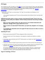
System Information, and then click Communications. S-Video (TV)
You can connect a TV with an S-Video connector to your computer. Figure 7 shows the location of the SVideo connector.
Figure 7. Connecting a TV
To connect your computer to a TV, follow these guidelines:
If your TV uses an S-Video cable for video input:
1. Connect the S-Video cable to your computer's S-Video TV-out connector (see Figure 7). 2. Connect the other end to your TV's S-Video connector. Connecting the S-Video cable that came with your TV to the TV's S-Video connector
and to the computer's S-Video TV-out connector allows your computer to play video
on the TV.
If your TV uses a composite video cable for video input:
1. Connect the composite TV-out adapter cable that came with your computer to your
computer's S-Video TV-out connector (see Figure 7).
2. Connect the other end of the composite TV-out adapter cable to your TV's composite video
cable.
3. Connect the composite video cable to your TV's composite video connector.
You need both the composite TV-out adapter cable that came with your computer and the
composite video cable that came with your TV. Connecting these cables together, then
connecting them to your TV composite video-in connector and your computer's S-Video TV-out
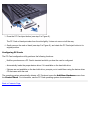
connector, allows your computer to play video on the TV. Audio Devices
You can connect audio devices such as speakers, microphones, and headphones to your computer. Figure
8 shows the locations of the audio jacks and the S-Video connector.
Connect the audio cable from a microphone to the microphone jack, also called the MIC IN jack.
Connect speakers or headphones to the headphones/speakers jack, also called the LINE OUT jack.
Connect the S-Video cable from a record/playback device to the S-Video connector. See "S-Video
(TV)." VCRs and video cameras are record/playback devices.
Figure 8. Connecting Audio and S-Video Devices
1 Headphones/speakers (LINE OUT)
jack
2 Microphone (MIC IN) jack
3 S-Video connector
Back to Contents Page
Back to Contents Page
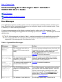
Microsoft® Windows® XP Features: Dell™ Latitude™
C500/C600 User's Guide
Overview
New User Interface
Files and Settings Transfer Wizard
Application and Device Compatibility
System Restore
User Accounts and Fast User Switching
Home and Small Office Networking
Internet Connection Firewall
Overview
Based on an enhanced version of the Windows 2000 operating system, Windows XP is available in
consumer and business editions: Windows XP Home Edition and Windows XP Professional. The features
discussed are available in both editions, but the Professional version, designed for business environments,
includes additional productivity, security, networking, and management features important in business
environments.
For home users, Windows XP brings the significantly increased stability and security inherent in the Windows
2000/Windows NT® operating systems. It also provides better support for portable computers. Key new
Windows XP features include:
An improved desktop and user interface
Files and Settings Transfer Wizard
Application program compatibility enhancements
System Restore
Fast User Switching*
Expanded home and small office networking functions*
A personal firewall for always-on Internet connections*
*Home and small office features
Help and Support Center
The Help and Support Center, introduced with Microsoft Windows Millennium Edition (Me), replaces
Windows Help from earlier operating systems. The Help and Support Center provides an integrated resource
center for information and assistance in using, configuring, and troubleshooting your computer and installed
hardware devices and software. For Windows XP, the Help and Support Center features expanded search
capabilities, including full-text search and the capability to search across multiple remote sites in addition to
files resident on the hard-disk drive. You can use a single print command to print an entire chapter of help
content.
To open Help and Support Center, click the Start button, and then click Help and Support. From the
home page, you can conduct a search or select categories of information, leading to task and information
topics covering the use of your computer. Click User and System Guides for information on using your
Dell™ computer, including installed hardware devices and software.
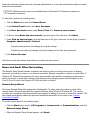
New User Interface
Windows XP features a redesigned user interface with a new visual style, a less cluttered desktop, and builtin desktop cleanup features. Window layout has also been changed for Windows XP and, as in the Control
Panel, emphasizes task presentation. The Start menu has been redesigned. The left half of the new Start
menu includes the most frequently used icons. As you use your computer, the icons in this area are changed
and rearranged depending on your computer usage patterns. If you wish to keep one of the icons
permanently in its location, right-click the icon and click Pin to Start menu.
To access all the programs installed on the computer, click All Programs at the bottom of the Start
menu. The right half of the new Start menu contains useful icons for accessing your files, configuring the
computer, and finding information and assistance. The Dell Solution Center icon opens a portal to
services and application programs installed on your Dell computer.
Switching to Classic View
If you wish, you may change the appearance of the Start menu, desktop and windows, or Control Panel
layout to that of earlier Windows operating systems. These classic view options are independent of each
other.
You can easily switch back and forth between the new Control Panel category view and the classic icon view
by clicking Switch to Classic View or Switch to Category View in the upper left area of the
Control Panel window. This can be handy if you would like to take advantage of the new, task-oriented
features of the Windows XP Control Panel, but you are accustomed to performing a particular task with the
icon-oriented classic Control Panel.
To change the appearance of the Start menu to the classic view:
1. Right-click the empty area on the task bar.
2. Click Properties.
3. Click the Start Menu tab.
4. Select Classic Start Menu and click OK.
If you prefer the classic window and button appearance, perform the following steps:
1. Right-click anywhere on the main desktop screen and click Properties.
2. Click the Appearance tab.
3. From the Windows and buttons dropdown box, select Windows Classic style.
4. To customize color, font, and other classic desktop options, click Advanced.
5. When you have completed your appearance selections, click OK.
Clean Desktop Wizard
Another feature of Windows XP is the Desktop Cleanup Wizard. The wizard runs 7 days after you first start
your computer and every 60 days after that. The Desktop Cleanup Wizard first opens a dialog box informing
you that there are unused icons on the desktop and asking whether you want to run the wizard. If you elect to
run the wizard, it places unused desktop icons in a folder.
The default for the Desktop Cleanup Wizard is on. To turn the wizard off:
1. Right-click anywhere on the main desktop screen and click Properties.
2. Select the Desktop tab and click Customize Desktop.
3. In the Desktop cleanup options make sure that the Run Desktop Cleanup Wizard every 60
days box is not checked.
You can run the Desktop Cleanup Wizard anytime by following these steps:
1. Right-click anywhere on the main desktop screen and select Properties.
2. Click the Desktop tab and click Customize Desktop.
3. Click Clean Desktop Now.
4. When the Desktop Cleanup Wizard appears, click Next>.
5. In the Shortcuts list, deselect any shortcuts you want to leave on the desktop, and then click Next>.
6. Click Finish to remove the shortcuts and close the wizard.
Taskbar Grouping
The Windows taskbar is a row of buttons that typically displays across the bottom of the screen. The taskbar
includes the Start button and a button for each open application. (The taskbar also includes the Quick
Launch icons and the notification area.) Windows XP groups multiple instances of the same application on
the taskbar. For example, if six instances of Internet Explorer are open, each displaying a button on the
taskbar, Windows XP groups the buttons next to one another on the taskbar. If space becomes an issue on
the taskbar, Windows XP consolidates all the Internet Explorer buttons into a single button. When clicked,
that button expands to a menu of the six Internet Explorer active sessions.
Notification Area Cleanup
Over time, software icons tend to proliferate in the notification area, the area in the bottom right corner of the
Windows desktop. Windows XP detects when icons in the notification area are not being accessed and hides
them. A caret, or chevron, button indicates that there are hidden icons that can be viewed by selecting the
button. You can also configure the notification area manually by right-clicking the taskbar, selecting
Properties, and then clicking Customize... in the Taskbar and Start Menu Properties window.
For example, you may choose to hide the antivirus program icon because it is rarely accessed, but display
the audio volume icon because it is used frequently. The notification area cleanup feature is automatically
enabled when the operating system is installed, but you may disable it by unchecking Hide inactive
icons in the Taskbar and Start Menu Properties window.
Files and Settings Transfer Wizard
The Files and Settings Transfer Wizard is used to migrate personal files and settings from one computer to
another (for instance, when upgrading to a new computer). Personal files include the documents, images,
spreadsheets, presentations, and e-mail messages on your computer. User settings include display
properties, window sizes, toolbar settings, dial-up connections, Internet bookmarks, and so forth on your
computer. The Files and Settings Transfer Wizard is run on a source (old) computer to collect the data and is
run again on the destination (new) computer to import the data. If the old computer is using an earlier
operating system, the wizard can be launched either from the Windows XP CD or from a diskette created on
the new Windows XP computer. You transfer the data to the new computer over a network or direct serial
connection, or store it on a removable medium such as a diskette, Zip disk, or writable CD.
To use the Files and Settings Transfer Wizard:
1. On the new Windows XP computer, click the Start button, point to All Programs—> Accessories
—> System Tools, and click Files and Settings Transfer Wizard.
2. On the Files and Settings Transfer Wizard welcome screen, click Next>.
3. On the Which computer is this? screen, select New Computer, and then click Next>.
The Do you have a Windows XP CD? screen appears.
The Files and Settings Transfer Wizard guides you through the steps necessary to transfer user settings,
personal files, or both to the new computer. If a CD drive is not available, the wizard allows you to create a
wizard diskette to run on your old computer.
NOTE: The time required to collect and transfer data depends on the amount of data collected. Times
can vary from just a few minutes to several hours.
Application and Device Compatibility
Although Windows XP is designed to be compatible with a wide range of application programs and hardware
devices, some older programs and devices may not be usable. Check the Microsoft Web site at
www.microsoft.com for application programs and hardware devices known to be compatible. When
buying new software and devices, look for those that are labeled as ready for Windows XP. If you encounter
problems using an application program designed for an earlier Windows operating system, Windows XP
provides a compatibility mode feature (see "Program Compatibility Wizard"). If you are unsuccessful at
installing application programs or hardware devices designed to operate on earlier Windows operating
systems, contact the manufacturer of the product for information or updates for Windows XP.
Windows XP also includes a new technology that addresses the problems sometimes encountered on
previous operating systems with Windows application programs that, when installed, replace current versions
of certain Windows files with older versions. This situation can cause problems with the newer application
programs, which rely on the replaced files. To eliminate this problem and improve operating system stability,
Windows XP manages multiple versions of files and invokes the correct version required by a program.
NOTE: If you experience problems with your operating system or other applications after performing
an installation, you can use System Restore to return your computer to a previous stable condition.
Program Compatibility Wizard
A program compatibility feature is provided in Windows XP that solves some issues that may be encountered
when attempting to run older application programs. Using the Program Compatibility Wizard, you can
configure a program to run in an environment closer to Windows 95, Windows 98/Me, Windows NT 4.0 with
Service Pack 5, or Windows 2000.
To use the Program Compatibility Wizard:
1. Click the Start button, point to All Programs—> Accessories, and click Program
Compatibility Wizard.
2. When the Program Compatibility Wizard appears, click Next>.
3. Select how you want to locate the program to run with compatibility settings: from a list, available on a
CD, or manually located. Then click Next>.
4. Select the type of operating system for which the program was designed or on which it ran successfully,
and then click Next>.
5. If necessary, as for some games, select display settings for the program.
6. Click Next>.
7. To test the compatibility settings for the program, click Next>.
After you have determined whether the program is running correctly, return to the Program
Compatibility Wizard window.
8. Select Yes if the program ran correctly, No, try different compatibility settings, or No, I am
finished trying compatibility settings and click Next>.
9. Select either Yes to send information about the settings you used and whether they fixed the problem,
or select No, and then click Next>.
10. Click Finish to close the wizard.
System Restore
The System Restore feature of Windows XP provides the capability to restore the operating system, in the
event of a problem, to a previous state without losing personal data files (such as Word documents,
drawings, or e-mail).
System Restore actively monitors system file changes and some application file changes to record or store
previous versions before the changes occurred. System Restore maintains a rolling record of restore points;
to limit the amount of space used, older restore points are purged to make room for newer ones.
In the event of a serious operating system problem, System Restore can be used from Safe Mode or Normal
Mode to go back to a previous system state, restoring optimal system functionality.
NOTE: System Restore does not revert user data or document files, so restoring does not cause loss
of work, mail, or browsing history and favorites.
NOTE: Dell recommends that you make regular backups of your data files. System Restore does not
monitor changes to or recover your data files. In the event the original data on the hard-disk drive is
accidentally erased or overwritten or becomes inaccessible because of a hard-drive malfunction,
backup files are required to recover lost or damaged data.
Using System Restore
System Restore monitors a core set of system and application program files, recording and sometimes
copying states of these files before changes are made. System Restore automatically creates restore points;
no user intervention is required. In addition, you can create restore points manually, if desired.
Restore points are created to allow you to choose previous system states. Each restore point gathers the
necessary information needed to restore to a precisely chosen system state. There are three types of restore
points:
System (automatically created) restore points (scheduled by your computer)
Installation (event-triggered) restore points (when a program is installed)
Manual restore points (created by you as needed)
Scheduled Automatic Restore Points
By default, System Restore creates a restore point every day that the computer is running. If your computer
is off for more than a day, a new restore point is created the next time you turn the computer on.
Event-Triggered Restore Points
Event-triggered restore points are created before key changes are made to the system. System Restore
automatically creates a restore point before the following events:
Application installations — System Restore creates a restore point before you install an application
program designed for Windows XP. You may wish to create a manual restore point before attempting to
install an older program.
AutoUpdate installation — When you choose to install the update, System Restore creates a restore
point before the actual installation of the update begins.
Restore operation — The restore operation itself also creates a restore point for undo purposes.
Microsoft Backup Utility recovery — Before Microsoft Backup Utility (only available in Windows XP
Professional) performs a backup recovery, System Restore creates a restore point.
Unsigned driver installation — The INF installer of Windows detects unsigned device-driver
installations. Drivers that are signed (electronically certified by the device manufacturer) do not
generate a restore point.
Manual Restore Points
If you are logged on to the computer as computer administrator or as a user with administrator rights, you
may create and name an on-demand restore point. (For information on types of user accounts, see "How to
Add Users.") This is useful to create a checkpoint to return to before making a particularly risky change,
before leaving a shared system to other users, or at a particular state you believe is optimal.
To create a restore point, perform the following steps:
1. Click the Start button, point to All Programs—> Accessories—> System Tools, and then
click System Restore.
2. Select Create a restore point and click Next>.
3. Type a description of the restore point and click Create.
The date and time are automatically added to the description of the new restore point.
Restore Process
As the computer is used over time, restore points are collected in the archive without any management or
intervention. If you encounter operating system problems, you can use the System Restore feature to select
any of the restore points presented through the System Restore Wizard.
If problems occur after installing a device driver, you should first attempt to use Driver Rollback. If that is
unsuccessful, then use System Restore.
To return your computer to a previous, stable condition, perform the following steps:
1. Click the Start button, point to All Programs—> Accessories—> System Tools, and then
click System Restore.
2. Select Restore my computer to an earlier time and click Next>.
The Select a Restore Point screen appears. The calendar on the left indicates in bold the dates on
which restore points were created.
3. Click a date, click a restore point for that date, and click Next>.
4. Click Next> to confirm the restore point selection and complete the restore process.
After System Restore finishes collecting data, the computer automatically restarts and the Restoration
Complete screen appears.
5. Click OK.
If you are not satisfied with the results of the restoration, you can repeat the preceding steps, using a
different restore point, or you can undo the restoration.
To undo a restoration, perform the following steps:
1. Click the Start button, point to All Programs—> Accessories—> System Tools, and then
click System Restore.
2. Select Undo my last restoration and click Next>.
3. Click Next> to confirm the restoration undo.
After System Restore finishes collecting data, the computer automatically restarts and the Undo
Complete screen appears.
4. Click OK.
Driver Rollback
Windows XP device Driver Rollback can replace a device driver with the previously installed version. When
you install a new device driver that causes system instability, use Driver Rollback to reinstall the previous
drivers. In the event that Driver Rollback cannot reinstall your previous driver, you can use System Restore
to return your operating system to its state before the new device driver installation.
To use Driver Rollback, perform the following steps:
1. Click the Start button, and then right-click My Computer.
2. Click Properties.
3. Click the Hardware tab, and then click Device Manager.
4. In the Device Manager window, right-click the device for which the new driver was installed, and
then click Properties.
5. Click the Drivers tab, and then click Roll Back Driver.
User Accounts and Fast User Switching
NOTE: Fast User Switching is the default user screen for both Home and Professional editions, but is
disabled in Windows XP Professional when the computer is a member of a computer domain.
Microsoft Windows XP includes a new feature that provides multiuser access to a single computer. Fast User
Switching, which is available in both the Home and Professional editions, allows users to access the
computer with their specific settings, including the desktop and various applications, without requiring the
previous user to log off. New users log on and switch from the original user's session to their own. New
users can run their desktop and applications without interfering with the original user. When the original user
returns, that user can switch back to the desktop and applications with the original settings. All of this is
accomplished without the delay of each individual user logging off the computer.
During setup, the computer administrator creates all the accounts that will be used on the computer. (For
information on types of accounts and adding new accounts, see "How to Add Users.") When the computer
starts, the main user screen appears with all of the user names. From this screen you select an account and
log in to that session.
How to Use Fast User Switching
To access Fast User Switching, perform the following steps:
1. Click the Start button and click Log Off.
2. When the Log Off Windows screen appears, click either Switch User or Log Off.
When you select Switch User, the main user screen appears. You can then select your account name
and log in. Your personal desktop appears.
What Happens When a Fast User Switch Occurs?
When a fast user switch occurs, the original user is not logged off the computer as previously happened on
other Microsoft operating systems. On Windows XP, the user's logon remains active, but is replaced by the
new user. Users can switch between login IDs as often as they want.
However, user applications active during a user switch remain active and running in the background while
the new user is working; this can result in a slower computer until the process finishes. For example, if one
user is downloading a large file from the Internet and another user logs on to the computer, the file download
continues in the background until it is complete.
While most applications continue to run in the background during a fast user switch, multimedia applications
do not. Because multimedia applications use resources that cannot easily be shared between different users
on a single computer, those applications terminate during the user switch, allowing the new user to take full
advantage of the multimedia capabilities.
Special Considerations With Fast User Switching
Considerations when using Fast User Switching include:
Some older Windows games may not operate with a fast user switch.
Multimedia games may shut down on a fast user switch.
DVD software shuts down and requires a restart when the user comes back.
Computers with low memory configurations can experience problems. The computer uses memory to
keep the first user's programs running in the background while the second user is logged on. On
computers with limited memory, this can cause the entire computer to run slowly. Fast User Switching
is off by default on computers with less than 128 megabytes (MB) of random-access memory (RAM).
Fast User Switching is unavailable if the computer has Windows XP Professional installed and is a member
of a computer domain.
How to Turn Off Fast User Switching
You must have a computer administrator account on the computer to turn off Fast User Switching. (For
information on types of accounts, see "How to Add Users.")
To disable Fast User Switching, perform the following steps:
1. Click the Start button, and click Control Panel.
2. In the Control Panel window, click User Accounts.
3. Under Pick a task, click Change the way users log on or off and do one of the following:
Select the Use Fast User Switching to log off check box to enable Fast User Switching.
Deselect the Use Fast User Switching to log off check box to disable Fast User
Switching.
4. Click Apply Options.
How to Add Users
Only a computer administrator or a user with administrator rights can create multiple user accounts. The
individual who performs the initial operating system setup creates a computer administrator account and can
add any number of users during the initial setup. All user accounts created during setup have administrator
rights.
After initial operating system setup, the computer administrator or a user with administrator rights can create
additional user accounts.
NOTE: Different account options are available when a Windows XP Professional computer is
connected to a domain.
To add users, perform the following steps:
1. Click the Start button, and click Control Panel.
2. In the Control Panel window, click User Accounts.
3. In the User Accounts window under Pick a Task, click Create a new account.
4. In the box under Name the new account, type the name of the new user. Click Next>.
5. Under Pick an account type, click the bullet next to the type of account you are going to create —
Computer administrator or Limited.
Computer administrators can change all computer settings.
Limited account users can change only a few settings such as their own passwords.
6. Click Create Account.
After the accounts are created, each shows up on the main user screen.
Home and Small Office Networking
The Network Setup Wizard includes a checklist and steps to guide you through the process of sharing
resources, such as files, printers, or an Internet connection, between computers in a home or small office. In
Windows XP, Microsoft has improved the online documentation and usability of operating-system tools for
setting up a home or small office network. New features in the operating system include support for the
Point-to-Point Protocol over Ethernet (PPPoE) and a built-in firewall.
Network Setup Wizard
The Home Network Wizard first appeared in Windows Me. To make setting up a home or small office
network easier, Microsoft developed an enhanced Network Setup Wizard for Windows XP. This version
provides more complete online documentation and support for setting up a home or small office network. The
new wizard automatically enables the personal firewall discussed later in this section (see "Internet
Connection Firewall").
To use the wizard, perform the following steps:
1. Click the Start button, point to All Programs—> Accessories—> Communications, and click
Network Setup Wizard.
2. When the Network Setup Wizard appears, click Next>.
3. Click checklist for creating a network.
The checklist leads you through the steps necessary to set up a home or small office network and provides
extensive references for each step. When you have completed the necessary connections and preparations,
return to the Network Setup Wizard.
4. Select the Internet connection method and click Next>.
5. Select the desired Internet connection if required, and click Next>.
6. Type a description of the computer and a computer name, and then click Next>.
7. Review the network settings and click Next> to finish the setup.
8. When the setup process is complete, click Finish to close the wizard.
Internet Connection Firewall
Today's always-on cable modem and DSL Internet access connections offer unprecedented bandwidth to
the home, but also leave the connected computer or home network vulnerable to hacker attacks. The nature
of these attacks varies, but the goal is to gain access to individual computers attached to the Internet. With
this access, a hacker can browse the hard-disk drive and add or delete files, discover passwords and credit
card numbers, and set the system up to launch attacks on other systems or websites. As a result, firewall
protection from these attacks is increasingly required on computers. Recognizing this need, Microsoft
provides an integrated firewall in Windows XP to provide immediate protection from outside access attempts.
When enabled, the Internet Connection Firewall provides basic protection suitable for most home and small
office users. The Internet Connection Firewall is disabled when the computer is connected to a domain.
NOTE: Enabling the Internet Connection Firewall does not reduce the need for virus-checking
software.
The firewall is automatically enabled when you run the Network Setup Wizard. When the firewall is enabled
for a network connection, its icon appears with a red background in the Network Connections portion of
the Control Panel. The Internet Connection Firewall can be applied to each Internet connection on the
computer. The firewall also provides basic logging capabilities. Not all events that appear in the log are
hacker attacks. Many different types of harmless events can appear in the log, such as routine checks by an
Internet Service Provider to verify the presence of your computer (pings).
The firewall is configured using the Properties dialog box associated with each Internet connection in the
Control Panel. The firewall can be enabled or disabled. Additional configuration options are available for
more advanced users. These advanced options include the ability to open or close specific Transmission
Control Protocol (TCP) or User Datagram Protocol (UDP) ports or to enable port redirection. Port redirection
allows access requests to a specific port on the firewall (such as port 80, the Web server port) to be
automatically redirected to another computer on the local network. This capability allows a Web server on a
home network to be protected by an edge firewall.
Back to Contents Page
Back to Contents Page
Using Intel® SpeedStep™ to Set Performance Levels:
Dell™ Latitude™ C600/C500 User's Guide
Using Intel SpeedStep
Using the Adjust Properties Option
Setting the Advanced Options
Using Intel SpeedStep
NOTES: Intel SpeedStep technology is only available for C600 computers. The Intel SpeedStep technology allows you to set the performance level of the microprocessor whether the
computer is running on battery or AC power. You can only use the Intel SpeedStep technology applet when
the Microsoft® Windows® 98, or Windows 2000 operating system is running. You can verify or change the
processor's performance mode when running in MS-DOS® mode by entering the system setup program.
The first page lists the processor speed ranges. To access the Intel SpeedStep properties window, perform the following steps:
1. Right-click the flag icon in the system tray on the Windows taskbar to access performance level
options. The following three options appear:
Maximum Performance option — switches your computer to the highest possible
performance level even if the computer is running on battery Battery Optimized Performance option — lets your computer run on performance
level optimized for battery power even if the computer is connected to an electrical outlet Adjust Properties — lets you change more performance options
2. To change the performance level, click the desired option.
To access the Intel SpeedStep options when the flag icon is not visible on the taskbar and if your computer is
running under ACPI, perform the following steps:
1. Click the Start button and point to settings.
2. Click Control Panel.
3. Click Power Management.
4. Select the Intel SpeedStep tab and select the options desired.
5. After you make any changes, click OK to accept the settings and close the Intel SpeedStep window.
Using the Adjust Properties Option
1. To access the Intel SpeedStep option window, either right-click the flag icon and click the Adjust
Properties option or double-click the flag icon.
The Intel SpeedStep technology options window opens.
2. You can adjust the following performance options:
Automatically change performance when the power source changes (the
default) — changes the performance level of your computer automatically when it is running
on battery or connected to an electrical outlet.
Ask me before automatically changing performance — when selected, the
computer prompts you for confirmation before the computer changes performance level.
Running on batteries and Plugged in pull-down menus — change performance level
options.
3. Click Apply to accept the settings.
4. Click OK to close the Intel SpeedStep technology options window.
Setting the Advanced Options
The Advanced options lets you disable various options. To set Advanced options, perform the following
steps:
1. Click the flag icon in the Windows system tray on the taskbar.
2. Click the Adjust Properties option.
The Intel SpeedStep window opens.
3. Click the Advanced button.
The Advanced window opens.
4. Click any of the following options:
Disable Intel SpeedStep technology control
If you disable Intel SpeedStep through the Advanced options, you can only change
processor speed through the system setup program. Remove flag icon.
Disable audio notification when performance changes.
5. Click Apply to accept the settings.
6. Click OK to close the Intel SpeedStep technology window.
Back to Contents Page
Back to Contents Page
Passwords and Security: Dell™ Latitude™ C600/C500
User's Guide
About Passwords
Using a Hard-Disk Drive Password
Using a Primary Password
Assigning an Asset Tag
Using an Administrator Password
Using the Security Cable Slot
About Passwords
A primary password prevents unauthorized access to the computer at start-up. An administrator password
can be used in place of the primary password. A hard-disk drive password helps prevent the unauthorized
access of data on the hard-disk drive, even when the device is placed into another computer.
NOTES: All three passwords are disabled when you receive your computer. You need to assign those
passwords if you require password security for your computer. Some companies may assign any or
all of these passwords before distributing the computer.
NOTICE: The password features provide a high level of security for the data in your
computer or hard-disk drive. However, they are not foolproof. If your data requires
more security, you should obtain and use additional forms of protection, such as data
encryption programs or PC Cards with encryption features.
If you forget any of your passwords, call Dell. For your protection, Dell’s technical support staff will ask you
for proof of your identity to make sure that an unauthorized person is not trying to use the computer.
Using a Primary Password
The primary password allows you to protect the computer from unauthorized access.
After assigning a primary password, you must enter it each time you turn on your computer. The following
message appears each time you turn on the computer:
Please type in the primary or administrator password and press <Enter>.
To continue, type your password and press <Enter>.
NOTE: If no password is entered within 2 minutes, the computer returns to its previous state.
If you have assigned an administrator password, you can use it instead of the primary password. The
computer does not specifically prompt you for the administrator password.
NOTICE: If you disable the administrator password, the primary password is also
disabled.
Using an Administrator Password
The administrator password is designed to give system administrators or service technicians in large
companies access to computers for repair or reconfiguration. The administrators or technicians can
assign identical administrator passwords to groups of computers as they are unpacked and configured,
leaving the primary password free to be assigned by the user.
When you set an administrator password, the Configure Setup option becomes available in the system
setup program. The Configure Setup option allows you to restrict access to the system setup program in
the same way a system password restricts access to the system.
The administrator password can be used in place of the primary password. Whenever you are prompted to
enter the primary password, you can enter the administrator password instead.
NOTE: The administrator password provides access to the system, but it does not provide access to
the hard-disk drive when it is protected by a password.
If you forget the primary password and do not have an administrator password assigned, or if you have both
a primary and an administrator password assigned but forget them both, call Dell.
NOTICE: If you disable the administrator password, the primary password is also
disabled.
Using a Hard-Disk Drive Password
The hard-disk drive password helps protect the data on your hard-disk drive from unauthorized access. You
can also assign a password for the modular hard-disk drive (if one is being used) that can be the same as or
different from the password for the primary hard-disk drive.
NOTE: Only hard-disk drives purchased from Dell for use with the Latitude C-Family portable
computers support the hard-disk drive password option.
After assigning a hard-disk drive password, you must enter it each time you turn on the computer and each
time you resume normal operation from suspend mode or standby mode.
If the hard-disk drive password is enabled, the following message appears each time you turn on the
computer:
Please type in the hard-disk drive password and press <Enter>.
To continue, enter the hard-disk drive password. Press <Esc> to return the computer to its previous state—
suspend or standby mode.
NOTE: If no password is entered within 2 minutes, the computer returns to its previous state.
If you enter the wrong password, the following message appears:
Invalid password
[Press Enter to retry]
If the correct password is not entered in three attempts, the computer tries to boot from another bootable
device if the Boot First device option in the system setup program is set to allow it. If the Boot First
device option is not set to allow booting from another device, the computer returns to the state it was in
when you turned it on—suspend or standby mode.
NOTES: If the hard-disk drive password, the modular hard-disk drive password, and the primary
password are the same, you are prompted only for the primary password. If the hard-disk drive
password is different from the primary password, you are prompted for both. Two different passwords
provide greater security.
The administrator password provides access to the system, but it does not provide access to the
hard-disk drive when it is protected by a password.
Assigning an Asset Tag
The Asset Tag utility allows you to enter an asset tag number that you or your company assigns to the
computer. The default system setup screens do not show the asset tag number unless you enter one by
using this utility.
You can also use the Asset Tag utility to enter an owner tag that appears in the system log-on screen and
with the primary password prompt.
Viewing Existing Asset Tag and Service Numbers
To view existing asset tag and service tag numbers, perform the following steps:
1. Boot the computer from a bootable diskette or CD-ROM.
2. Type cd c:\Dell\Util and press <Enter>.
3. Type asset and press <Enter>.
Assigning an Asset Tag Number
An asset tag number can have up to ten characters; any combination of characters excluding spaces is valid.
To assign or change an asset tag number, perform the following steps:
1. Boot the computer from a bootable diskette or CD-ROM.
2. Type cd c:\Dell\Util and press <Enter>.
3. Type asset and a space followed by the new number, and press <Enter>.
For example, type the following command line and press <Enter>:
asset 1234$ABCD&
4. When the system prompts you to verify the asset tag number, type y and press <Enter>.
The system displays the new or modified asset tag number and the service tag number.
Deleting an Asset Tag Number
To delete the asset tag number without assigning a new one, perform the following steps:
1. Boot the computer from a bootable diskette or CD-ROM.
2. Type cd c:\Dell\Util and press <Enter>.
3. Type asset /d and press <Enter>.
Assigning an Owner Tag
An owner tag can have up to 48 characters; any combination of letters, numbers, and spaces is valid. To
assign an owner tag, perform the following steps:
1. Boot the computer from a bootable diskette or CD-ROM.
2. Type cd c:\Dell\Util and press <Enter>.
3. Type asset /o and a space followed by the new owner tag, and press <Enter>.
For example, type the following command line and press <Enter>:
asset /o ABC Company
4. When the system prompts you to verify the owner tag, type y and press <Enter>.
The system displays the new owner tag.
Deleting an Owner Tag
To delete the owner tag without assigning a new one, perform the following steps:
1. Boot the computer from a bootable diskette or CD-ROM.
2. Type cd c:\Dell\Util and press <Enter>.
3. Type asset /o /d and press <Enter>.
NOTE: For security, you cannot set, change, or delete the owner tag if the primary or administrator
passwords are set.
Table 1 lists the command-line options you can use with the Asset Tag utility. To use one of these options,
open an MS-DOS® prompt, type asset and a space followed by the option, and then press <Enter>.
Table 1. Asset Tag Utility Command-Line Options
Asset Tag
Option
Description
/d
Deletes the asset tag number
/o tag
Specifies a new owner tag
/o /d
Deletes the owner tag
/?
Displays the Asset Tag utility help screen
Using the Security Cable Slot
To prevent unauthorized removal of the computer, you can use a security cable to attach the computer to an
immovable object. Your computer has one security cable slot, located on the left side of the computer—
between the speaker and the hard-disk drive (see Figure 1).
The security cable slot allows you to attach a commercially available antitheft device to the computer.
Antitheft devices for portable computers usually include a segment of metal-stranded cable with an attached
locking device and associated key.
Basic Instructions for Using the Security Cable Slot
To prevent unauthorized removal of your computer, loop the cable around an immovable object, insert the
locking device into the security cable slots, and lock the device. See Figure 1 for an example of how to
secure your computer. Complete instructions for installing this kind of antitheft device are usually included
with the device.
Figure 1. Securing the Computer
NOTE: Antitheft devices are of differing designs. Before purchasing such a device, make sure that it
will work with the security cable slot in your computer.
Security and Docking Device
If your computer is installed in a Dell Latitude docking device, use the security cable slot on the docking
device to secure the computer. See your docking device User's Guide for the location of the security slot.
You can use the security cable slot to secure your computer when it is not docked to a Dell Latitude docking
device. However, to lock your computer and prevent unauthorized removal of the hard-disk drive, insert the
locking device into the security cable slot located between the hard-disk drive and the speaker, and lock the
device with its associated key.
Back to Contents Page
Back to Contents Page
Traveling With Your Computer: Dell™ Latitude™
C600/C500 User's Guide
Identifying Your Computer
Preparing Your Computer for Travel
Travel Tips
Identifying Your Computer
As an antitheft measure, assign a primary password and a hard-disk drive password to prohibit unauthorized
access to the computer.
Dell recommends that you follow these precautions before you travel with your computer:
Write down your service tag number, and put it in a safe place separate from the computer or carrying
case. If the computer is lost or stolen, use the service tag number when reporting to law enforcement
officials and to Dell.
Use a text editor (such as Microsoft® Windows® Notepad) to create a file called if_found in your root
directory. Place information such as your name, address, and telephone number in this file. (For
instructions on using the appropriate text editor, see the documentation that came with your operating
system.)
Attach your business card or other name tag to the computer.
Contact your credit-card company and ask if it offers coded identification tags that allow your property
to be returned to you without the risk of revealing your name, address, or telephone number.
Use a permanent marking or stenciling device to write your driver’s license number or some other
unique identifying mark on the computer. If a lost or stolen computer is recovered, such marking
identifies the computer as your property.
Service Tag Number
The service tag number is an alphanumeric code on a bar code label located on the bottom of the computer.
The number is unique to your computer and allows Dell technical assistance personnel to identify the
computer and its configuration quickly if you call for assistance.
If Your Computer Is Lost or Stolen
If your computer is lost or stolen, Dell suggests that you perform the following steps:
1. Call a law enforcement agency to report the lost or stolen computer.
Include the service tag number in your description of the computer. Ask that a case number be
assigned, and write it down. Also write down the name, address, and telephone number of the
law enforcement agency. If possible, obtain the name of the investigating officer.
If you know where the computer was lost or stolen, call a law enforcement agency in that area. If
you do not know, call a law enforcement agency where you live.
2. If the computer belongs to a company, notify the security office of the firm.
3. Call Dell technical assistance to report the missing computer.
Provide the computer’s service tag number, the case number, and the name, address, and
telephone number of the law enforcement agency to which you reported the missing computer. If
possible, give the name of the investigating officer.
The Dell support technician will log your report under the computer’s service tag number and flag
the computer as missing or stolen. If someone calls Dell for technical assistance and gives your
service tag number, the computer is identified automatically as missing or stolen. The technician
will attempt to get the phone number and address of the caller. Dell will then contact the law
enforcement agency to which you made the report of the missing or stolen computer.
Preparing Your Computer for Travel
To prepare your computer for travel, perform the following steps:
1. Remove any external devices attached to the computer, and store them in a safe place. If a diskette is
in the diskette drive, remove it. Remove any cables attached to installed PC Cards (you do not have to
remove the PC Cards themselves).
2. To make the computer as light as possible, remove the storage device (if installed) from the modular
bay and install the travel module.
3. To maximize battery life, check the charge on your battery. Then fully charge the battery and any
spares you plan to carry with you.
4. Turn off the computer.
NOTICE: When you disconnect the AC adapter from the computer, grasp the adapter
cable's connector, not the cable itself, and pull gently but firmly to avoid damaging the
cable.
Disconnect the AC adapter.
NOTICE: When the display is closed, items left on the keyboard could damage the
display.
6. Make sure that there is nothing on the keyboard and palmrest that can damage the display when you
close it. Then close the display.
7. Pack all your computing accessories.
With the optional Dell carrying case, you can pack the computer and its accessories together.
NOTE: Follow the travel tips and take special precautions if you are planning to travel by air.
Traveling by Air
You may want to take the following precautions when you are traveling by air with your computer: Notify airport security in advance that you are bringing a portable computer.
Be sure to have a charged battery or the AC adapter and power cable available in case you are asked
to turn on the computer.
Do not check the computer as baggage.
NOTICE: Have airport security personnel check the computer by hand. If the computer
passes through a metal detector, data loss may occur. If you must pass the computer
through a metal detector, first remove the hard-disk drive.
Do not put the computer through a metal detector.
The computer can go through an airport X-ray security machine.
Before you use the computer on an airplane, check the in-flight magazine or ask the flight crew to verify
that such use is permitted. Some airlines forbid the use of electronic devices during the flight. All
airlines forbid the use of electronic devices during takeoff and landing.
Dell has several carrying cases that protect the computer and accessories during travel.
If you pack the computer in a suitcase, do not pack so tightly that the computer display breaks or so
loosely that the computer slides around.
Avoid packing the computer with items such as shaving cream, colognes, perfumes, or food.
Protect the computer, the battery, and the hard-disk drive from hazards such as extreme temperatures;
overexposure to sunlight; and exposure to dirt, dust, or liquids.
Pack the computer so that it does not slide around in the trunk of your car or in an overhead storage
compartment.
If you are carrying a second hard-disk drive separately, protect the drive from exposure to static
electricity by placing the drive in an antistatic bag or wrapping it in a nonconductive fabric.
Travel Tips
Consider changing the settings of your power management options to maximize battery life if you will
be using battery power for extended periods.
If you are traveling internationally, carry proof of ownership to speed your passage through customs. If
the computer is provided by your employer, carry documentation of your right to use the computer.
Investigate the customs regulations of the countries you plan to visit, and consider acquiring an
international carnet from your government if you travel through many different countries.
Power interruptions can occur frequently in some countries. Always have a charged battery available if
traveling abroad.
Credit card holders should check with their credit card companies for information about the kinds of
emergency travel assistance they offer to users of portable computers. Many companies provide
services that help you solve problems, such as quickly locating 3.5-inch diskettes or providing a directdial telephone line for your modem connection.
NOTICE: Do not use removable media devices while the computer is in motion.
Vibrations could interrupt the flow of data to and from the device and the hard-disk
drive.
Carnet
A carnet is an international customs document (also known as a merchandise passport) that facilitates
temporary imports into foreign countries and is valid for up to 1 year.
Back to Contents Page
Back to Contents Page
Removing and Replacing Parts: Dell™ Latitude™
C600/C500 User's Guide
Preparing to Work Inside the Computer
Replacing a Primary Hard-Disk Drive
Removing or Installing Memory Modules
Preparing to Work Inside the Computer
NOTES: If necessary, print these instructions for reference before proceeding.
Before you start to work on the computer, perform the following steps.
NOTICE: Failure to perform the following steps could result in damage to the computer.
1. Save any work in progress and close all open application programs.
2. Turn off the computer and any attached devices.
NOTE: Make sure that the computer is turned off and not in save-to-disk suspend (S2D) mode.
If you cannot shut down the computer using the computer’s operating system, press the power
button for 4 seconds.
3. If the computer is docked, undock the computer.
4. Disconnect the computer and any attached devices from their electrical outlets to reduce the potential
for personal injury or shock. Also disconnect any telephone or telecommunications lines from the
computer.
5. Remove the power cable.
6. Disconnect all other external cables from the computer.
7. Remove any installed PC Cards.
NOTICE: Make sure that the work surface is clean to prevent scratching the computer
cover.
NOTICE: To avoid damaging the system board, remove the power cable, the battery,
and the second battery (if installed) before you service the computer.
8. Remove the main battery from the battery bay.
9. Ground yourself by touching the unpainted metal surface of the input/output (I/O) panel on the back of
the computer.
While you work, periodically touch the I/O panel to dissipate any static electricity that might harm
components.
Replacing a Primary Hard-Disk Drive
NOTICE: To prevent data loss, turn off your computer before you remove the hard-disk
drive. Do not remove the hard-disk drive if the computer is in suspend mode or if the
drive access light is on. Removing the drive under these conditions will lead to loss of
data.
To replace a primary hard-disk drive, perform the following steps:
1. Complete the tasks as described in "Preparing to Work Inside the Computer."
2. Remove the hard-disk drive from the drive bay.
Close the display and turn the computer over. Using a small Phillips-head screwdriver, remove the
screw (see Figure 1) that holds the drive carrier in the drive bay. Save the screw for use later in this
procedure.
Figure 1. Removing a Hard-Disk Drive
3. As shown in Figure 1, push up and pull out the drive carrier out of the drive bay.
When the hard-disk drive is not in the computer, protect the drive from exposure to static
electricity. See "Protecting Against Electrostatic Discharge" for more information.
4. Remove the new hard-disk drive from its packaging.
Save the original packaging to use when you store or ship the hard-disk drive.
5. Install the new hard-disk drive into the computer (it comes in a drive carrier).
NOTICE: If the drive carrier does not slide in easily, pull it out and try again. To avoid
damage, do not force the drive carrier into the bay.
6. Gently push the drive carrier into the drive bay until the carrier door is flush with the computer case.
7. Push down on the driver carrier until it snaps into place. 8. Replace the screw you removed in step 2. Be careful not to overtighten the screw.
If you have installed a new hard-disk drive, follow the directions that came with the drive to partition and
logically format the drive and to create a suspend-to-disk (S2D) partition.
NOTICE: Hard-disk drives are extremely fragile and must be handled carefully to avoid
damage. Follow these guidelines: The primary hard-disk drive is installed in a metal carrier to protect the drive and
make installation easier. When you remove and install hard-disk drives, handle the
drive carrier, not the drive itself.
Never press down on the top of the drive.
Do not drop the drive. Even a slight jar or bump can damage the drive heads and
spinning plates, thus rendering the drive inoperable.
CAUTION: The primary hard-disk drive may be hot to the touch under extreme
environmental conditions. If the drive is hot, allow it to cool before you replace it.
Preparing a New Primary Drive
Every primary hard-disk drive must be physically formatted, partitioned, and logically formatted before it can
be used to store data. Every primary hard-disk drive from Dell is physically formatted before it is sent to you.
Use the program(s) provided by your operating system to partition and logically format the hard-disk drive.
Removing or Installing Memory Modules
NOTICE: Your computer only supports 100-megahertz (MHz) synchronous dynamic
random-access memory (SDRAM) modules. It does not support extended-data out (EDO)
memory modules.
NOTICE: Do not install memory modules while the computer is in suspend, standby, or
suspend-to-disk mode. NOTICE: Ground yourself by touching an unpainted metal surface of a connector on the
back of the computer. While you work, periodically touch the connector to dissipate any
static electricity that might harm internal components.
To remove or install memory modules, perform the following steps:
1. Complete the tasks as described in "Preparing to Work Inside the Computer."
2. Close the display, and turn the computer upside down. 3. Remove the memory module cover: a. Using a small Phillips-head screwdriver, remove the two screws located on the memory
module cover. The screws are part of the memory module cover and stay with the cover
when you remove it. b. Locate the small semicircular indention at one end of the memory module cover. Place your
fingertip under the cover by the indentation and firmly lift the cover up. c. When the cover pops up, lift it up to remove it and expose the memory modules underneath
it.
4. If you are replacing a memory module, remove the old one.
Carefully spread apart the inner metal tabs of the memory module socket just far enough for the
memory module to disengage from the socket (it should pop up slightly). Then lift the memory module
away from the socket (see Figure 2).
Figure 2. Removing a Memory Module
1 JDIM 1 socket
2 JDIM 2 socket
5. Ground yourself and unpack the new memory module from the upgrade kit.
6. If you need to install memory modules in two sockets, install a memory module in the socket labeled
"JDIM 1" before you install a module in the socket labeled "JDIM 2." If you only have one memory
module, install it in the "JDIM 1" socket. (See Figure 2.)
Memory modules are keyed, or designed to fit into their sockets in only one direction. The slots on
the system board are notched so that the memory module can be firmly seated only one way.
7. Align the memory module’s edge connector with the slot in the center of the memory module socket.
8. With the module at a 45-degree angle, press the memory module’s edge connector firmly into the
memory module socket.
9. Pivot the memory module down until it clicks into place.
If you do not hear a click as each end of the memory module snaps into the metal tabs, remove
the memory module and reinstall it.
NOTICE: After installation, if the memory module cover does not fit or is difficult to
close, you may have installed the memory module improperly or into the wrong slots.
Remove the memory modules and reinstall them. Do not force the memory module
cover to close because you may damage your computer. 10. Replace the memory module cover as follows:
a. Set the memory module cover loosely over the opening, aligning the three tabs on the
memory module cover to the corresponding slots on the opening. These tabs are on the
opposite side of the cover from the screw holes. b. Rotate the cover down and reinstall the screws.
11. Reconnect your computer and devices to their electrical outlets and turn them on.
As the computer boots, it detects the presence of additional memory and automatically updates
the system configuration information. Verify that the correct memory total is displayed. If
necessary, repeat steps 1 through 9 until the memory total is correct
Back to Contents Page
Back to Contents Page
AC Adapter and Battery: Dell™ Latitude™ C600/C500
User's Guide
About the AC Adapter
First Low-Battery Warning
Connecting the AC Adapter
Second Low-Battery Warning
About the Batteries
Charging the Battery
Removing a Battery
Detecting Battery Problems
Installing a Battery
Battery Disposal
Checking the Battery Charge
About the AC Adapter
The AC adapter kit includes two cables: the AC adapter cable and an AC power cable.
You can connect the AC adapter with your computer either turned on or off.
The AC adapter works with electrical outlets worldwide. However, power connectors vary among countries.
Before you use AC power in a foreign country, you may need to obtain a new power cable designed for use
in that country.
If the computer is docked to a Dell C/Port Family Advanced Port Replicators (APR) or C/Dock Family
Expansion Stations, you can run the computer on AC power by connecting the AC adapter to the C/Port APR
or C/Dock Expansion Station.
NOTE: If you are running your computer on AC power with a battery installed, the AC adapter charges
the battery (if needed) and then maintains the battery's charge.
NOTICE: To avoid overheating the AC adapter when powering the computer or charging
the battery, use the AC adapter in a ventilated area, such as on a desktop or on the
floor. Do not use the AC adapter in a poorly ventilated environment, such as inside a
carrying case.
Connecting the AC Adapter
1 AC adapter cable
2 AC adapter power
cable
3 AC adapter
About the Batteries A lithium ion battery in the battery bay is standard with the computer, and provides power when an electrical
outlet is not available. To double battery life, install a second battery in the modular bay.
CAUTION: Do not puncture, disassemble, or incinerate the computer's battery.
The battery may present a fire or chemical burn hazard if mistreated. Do not
expose the battery to temperatures above 60° Celsius (C) (140° Fahrenheit [F]).
Keep the battery away from children. Handle damaged or leaking batteries with
extreme care. If the battery is damaged, electrolyte may leak from the cells and
cause personal injury.
Lithium ion batteries are longer lived than conventional batteries and do not require replacement as often.
There is no battery memory effect with a lithium ion battery—you can charge the battery whenever you like
without fear of reducing its charge capacity, and you do not need to drain a lithium ion battery completely
before recharging it.
Lithium ion batteries should not be disposed of with common household waste products. For battery disposal
information, contact local authorities for the location of a chemical waste collection program nearest you.
Keep the following information in mind when you are running your computer from the battery:
With a single fully charged, 8-cell lithium-ion battery, you can expect about 3 hours of battery life; with
two fully charged lithium-ion batteries, 6 hours of battery life. Actual performance varies, depending on
which power management features are enabled and which application programs are being used. When two batteries are installed, the computer draws power from the battery with the higher capacity
until both batteries are at the same charge level. Then it draws power from both. The AC adapter first
charges the battery in the battery bay.
The integrated charge gauge lets you check a battery’s charge before you insert it into the computer.
The battery’s self-test capability alerts you to battery conditions such as low charge.
The battery has a life span of around 400 discharge/charge cycles, provided it is charged at normal
room temperature.
Battery Usage
The battery is partially charged when you receive it. Dell recommends that you charge your battery to full
capacity before using it to power the computer. For information on conserving battery power, see "Power
Management Modes."
When you activate suspend mode (known as standby in the Microsoft® Windows® 98 and Windows 2000
operating systems), the computer can run on a fully-charged battery for approximately one week.
If you are going to store the computer, disconnect all peripheral devices and turn off the computer. Remove
the battery when you store your computer for an extended period of time. A battery will drain when not in use
during prolonged storage. After a long storage period, recharge the battery fully before you attempt to run
your computer from the battery.
Removing a Battery
CAUTION: Using the wrong battery type may present a risk of fire or explosion.
Replace the battery only with the same or equivalent type purchased from Dell.
You can use your computer's battery in any Latitude C-Family computer except for
the Latitude CS or CSx computers. Do not attempt to use the battery in CS or CSx
computers, and do not use a battery from those computers in your computer.
NOTICE: To avoid data loss, do not replace a battery while the computer is turned on
unless the computer is connected to an electrical outlet or a second battery is
installed. NOTICE: Only use lithium ion batteries in your computer. The computer does not
support nickel-metal hydride (NiMH) batteries. If you install a NiMH battery, the battery
status lights blink alternately green and amber.
NOTICE: If you choose to replace the battery with the computer in standby mode, you
have up to 4 minutes to complete the battery replacement. After 4 minutes, the
computer shuts down and you will lose any unsaved data.
1. Ensure that the computer is turned off, suspended in a power management mode, or connected to an
electrical outlet.
2. If the computer is docked, undock it.
3. Close the display and turn the computer over.
4. Slide and hold the battery bay (or module bay) latch release on the bottom of the computer, and then
remove the battery from the bay.
Figure 1. Removing a Battery
1 Battery
2 Battery bay latch
Installing a Battery
Slide the battery into the bay until the latch release clicks.
Checking the Battery Charge
To check the charge level, press the battery test button that is next to the lights (see Figure 2). The number
of lights that appear shows an estimate of the remaining battery charge (see Table 1).
Figure 2. Battery Charge Gauge and Test Button
Table 1. Percentage of Charge
No. of Lights Lit % Charge Remaining
5
81–100
4
61–80
3
41–60
2
21–40
1
1–20
The battery charge gauge consists of five lights. Each light represents 20 percent of full charge. If only one
light appears, recharge the battery before using it. NOTE: If the battery has a 0 (zero) percent charge, you cannot use the battery test button to check the
battery's capacity. The battery gauge indicator will not light if the battery is completely drained.
A light that blinks rapidly when you check the battery’s charge level indicates a temporary failure or a
potentially recoverable failure like overheating. Allow the battery to cool for several minutes before checking
the charge level again. If the battery is experiencing a permanent failure, the lights do not appear when you press the test button. If
you install a failed battery into the computer, the amber battery light on the computer flashes rapidly (see
Figure 3). To purchase a new battery, call Dell or access the Dell World Wide Web site at
http://www.dell.com. Dispose of the old battery properly.
First Low-Battery Warning
The first low-battery warning—a blinking amber battery light—occurs when you have about 15 minutes of
battery life left under current conditions and the computer is not connected to an electrical outlet. Figure 3
shows the battery status light.
Figure 3. Status Lights
1 Power light
2 Drive access light
3 Battery light
NOTICE: When you see a low-battery warning, save your work immediately. Then
replace the battery or connect your computer to an electrical outlet.
After the first low-battery warning, if no input/output (I/O) activity occurs within 75 seconds, the computer
activates suspend-to-disk mode. Once suspend-to-disk mode is activated, no further power is consumed. If
the computer has no suspend-to-disk partition, the computer enters suspend mode. The computer can
preserve data for several hours in suspend mode.
NOTICE: Never turn off the computer while the drive access light is on. Doing so could
cause data loss. Instead, close all of your application programs before you turn off the
computer.
Second Low-Battery Warning
The second low-battery warning—a steady amber battery light—occurs when you have about 5 minutes of
battery life left under current conditions and the computer is not connected to an electrical outlet.
After the second low-battery warning, if no further I/O activity occurs within 15 seconds, the computer
activates suspend-to-disk mode. If there is no suspend-to-disk partition, the computer enters suspend mode.
The computer can preserve data for several hours in suspend mode.
If the computer is already in suspend mode when a final low-battery warning occurs, the computer activates
suspend-to-disk mode immediately. If suspend-to-disk mode has been disabled, the computer reenters
suspend mode.
NOTICE: To avoid losing data (and possibly corrupting data areas on your hard-disk
drive), save your work immediately after a second low-battery warning. Then connect
your computer to an electrical outlet, or place the computer in suspend mode. If the
battery runs completely out of power, the computer shuts off without properly closing
any open files.
Charging the Battery
Each time you connect the computer to an electrical outlet or install a battery in a computer that is connected
to an electrical outlet, the computer checks the battery's charge. The AC adapter charges the battery (if
needed) and then maintains the battery's charge.
NOTE: For maximum battery performance, charge the battery only at normal room temperature. If two batteries are installed in the computer, the AC adapter first charges the battery in the battery bay, then
the battery in the modular bay.
When installed in a computer connected to an electrical outlet, the battery immediately starts charging. The
green power light remains steady while the AC adapter charges the battery. The power light starts blinking
when the Dell ExpressCharge™ cycle is complete. While the power light is blinking, the AC adapter provides
a trickle charge to bring the battery to full capacity. The power light continues to blink until you remove the
battery or disconnect the computer from its electrical outlet.
NOTICE: If the battery is hot from being used in your computer or being in a hot
environment, follow these precautions:
A hot battery will not charge when you connect the AC adapter to the computer.
This safety feature is important because charging a hot battery shortens the
battery’s life span and may damage the battery and the computer.
The battery is too hot to start charging if the battery light flashes alternately green
and amber. If this occurs while the computer is connected to an electrical outlet,
disconnect the computer from the outlet and allow the computer and the battery
to return to room temperature. Then reconnect the computer to its electrical outlet
and continue charging the battery. If the computer is not allowed to return to room temperature, the battery stops
charging before it reaches full capacity.
Charge Times
For lithium ion batteries, if the computer is turned off and connected to an electrical outlet through the AC
adapter, the computer uses ExpressCharge technology to charge the battery. ExpressCharge takes about an
hour to completely charge a fully discharged battery. If the computer determines that the battery is near full
capacity, the battery trickle charges instead of using ExpressCharge.
If the computer is on, it takes about the same time to charge, depending on which devices you are using and
which programs you are running. NOTE: You can leave the battery in the computer as long as you like. The battery's integrated circuitry
prevents the battery from overcharging.
Detecting Battery Problems
A battery problem may prevent the battery from being charged to its full potential and can lead to
unpredictable operation. To obtain a new battery, call Dell or access the Dell World Wide Web site at
http://www.dell.com.
Dell suggests you follow these precautions when using the battery:
To avoid installing a defective battery in your computer, check the battery's charge by pressing the
battery test button (see Figure 2). The battery gauge light will not light if the battery is completely
drained.
If, after you insert the battery in the computer, the computer's battery status light (see Figure 3) flashes
alternately green and amber, the battery is too hot to charge. Turn off the computer, and let the battery
and computer cool to room temperature.
If, after you insert the battery in the computer, the computer's battery status light (see Figure 3) flashes
amber for 4 seconds when you connect or disconnect the AC adapter or when you press the power
button, you need to replace the battery.
If, after you insert the battery in the computer, the computer's battery status light (see Figure 3) flashes
rapidly amber, the battery is defective and needs to be replaced.
Battery Disposal
When your battery no longer holds a charge, call your local waste disposal agency or environmental agency
for advice on disposing of it. To purchase a new battery, call Dell or access the Dell World Wide Web site at
http://www.dell.com. CAUTION: If your battery is damaged, or if it no longer holds a charge, dispose of
it promptly and properly. Do not dispose of it along with household waste. Call
your local waste disposal agency or environmental agency for advice on
disposing of the battery. Back to Contents Page
Back to Contents Page
Power Management and Conservation: Dell™ Latitude™
C600/C500 User's Guide
Management Tips
Power Options Properties
Power Management Modes
ENERGY STAR® Emblem
Management Tips
NOTE: See "About the Batteries" for more information on conserving battery power.
Connect the computer to an electrical outlet when possible, because the battery life expectancy is largely
determined by the number of times it is charged.
Place the computer in standby mode or hibernate mode when you leave the computer unattended for long periods
of time. If you are going to connect your computer to a port replicator or a docking station, click None (or Do nothing)
when you program the display-close option in theAdvanced tab in the Microsoft® Windows® Power Options
Properties window.
To exit a power management mode, press the power button.
Power Management Modes
Standby Mode (Suspend Mode)
Standby mode (also called suspend mode) conserves power by turning off the display and the hard-disk drive after a
predetermined period of inactivity (a time-out). When you exit standby mode, the computer returns to the same state it
was in before entering standby mode.
NOTICE: If your computer loses AC and battery power while in standby mode, you may lose data.
To enter standby mode in Windows XP, Windows 2000, or Windows 98:
If you are using Windows XP, click the Start button, click Turn Off Computer, and then click Stand By.
If you are using Windows 2000 or Windows 98, click the Start button, click Shutdown, click Standby, and then
click OK.
or
Depending on how you set the power management options in the Advanced tab, use one of the following
methods:
Press the power button.
Close the display.
Press the power management keyboard shortcut (sometimes referred to as the "sleep button"),
.
If an external monitor is connected to the computer when you close the display, the computer does not enter standby
mode. You can still use the external monitor.
To exit standby mode, press the power button or open the display depending on how you set the options in the
Advanced tab.
To enter standby mode in Windows NT:
To enter standby mode, press <FN><Esc>. For power management information, see Power Options Properties.
Hibernate Mode (Suspend-to-Disk Mode)
Hibernate mode (also called suspend-to-disk or S2D mode) conserves power by copying system data to a reserved area
on the hard-disk drive and then completely turning off the computer. When you exit hibernate mode, the computer returns
to the same state it was in before entering hibernate mode.
NOTICE: You cannot remove devices or undock your computer while in hibernate mode.
Your computer enters hibernate mode if the battery charge level becomes critically low.
Depending on how you set the power management options in the Advanced tab, use one of the following methods to
enter hibernate mode:
Press the power button.
Close the display.
Press the power management keyboard shortcut (sometimes referred to as the "sleep button"),
.
If an external monitor is connected to the computer when you close the display, the computer does not enter hibernate
mode. You can still use the external monitor.
NOTE: You cannot exit standby mode or hibernate mode by pressing a key or touching the touch pad.
NOTE: Some PC Cards may not operate correctly after the computer exits hibernate mode. Remove and reinsert
the card, or simply restart (reboot) your computer.
To exit hibernate mode, press the power button. The computer may take a short time to exit hibernate mode.
For more information on hibernate mode, see the documentation that came with your operating system.
Power Options Properties (Power Management Properties)
For Microsoft Windows XP
1. Click the Start button, and then click Control Panel.
2. Under Pick a category, click Performance and Management.
3. Under or pick a Control Panel icon, click Power Options.
For Microsoft Windows 2000 or Windows 98
To access the Windows Power Options Properties (or Power Management Properties) window:
1. Click the Start button, point to Settings, and then click Control Panel.
2. Double-click the Power Options Properties (or Power Management Properties) icon.
For Microsoft Windows NT
Dell provides Softex software compatible with the Power Management Controller, which allows you to suspend and
resume your computer without affecting your ability to use the docking station or its media bay.
For information on using any Softex application program, see the online Help:
1. Double-click the Softex program's icon in the system tray of the Windows taskbar (normally on the bottom-right side
of the screen).
2. Click Help. Power Schemes Tab
The Power schemes pull-down menu displays the selected preset power scheme. Depending on your operating
system, typical power schemes are:
NOTE: Dell recommends that you use the Portable/Laptop power scheme to maximize battery power.
Portable/Laptop
Home/Office
Always On
Presentation
Minimal Power Management
Max Battery
Each preset power scheme has different time-out settings for putting the computer into standby mode, turning off the
display, and turning off the hard-disk drive. For more information on power management options, see Windows Help or
Windows Help and Support Center.
Windows XP controls the performance level of the processor depending on the power scheme you select. You do not
need to make any further adjustments to set the performance level. For more information on setting processor
performance, see "Using Intel Speedstep."
Alarms Tab
NOTE: To enable audible alarms, click each Alarm Action button and select Sound alarm.
The Low battery alarm and Critical battery alarm settings alert you with a message when the battery charge
falls below a certain percentage. When you receive your computer, the Low battery alarm and Critical battery
alarm check boxes are selected. Dell recommends that you continue to use these settings. See "Battery Warnings" for
more information on low battery warnings.
Power Meter Tab
The Power Meter tab displays the current power source and amount of battery charge remaining.
Advanced Tab
The Advanced tab allows you to:
Set power icon and standby mode password options.
NOTES: If you are going to connect your computer to a port replicator or a docking station, click None when you
program the display-close option. This setting ensures that your computer does not enter standby mode or
hibernate mode when you close (lower) the display.
If the computer is running Windows 98, set power management options in the system setup program.
Program the following functions:
Activate standby mode.
Activate hibernate mode.
Shut down Windows and turn off the computer.
Choose no action (None).
To program these functions, click an option from the corresponding pull-down menu, and then click OK.
Hibernate Tab
The Hibernate tab lets you enable hibernate mode by clicking the Enable hibernate support check box.
ENERGY STAR® Emblem
The EPA’s ENERGY STAR® Computers program is a joint effort between the EPA and computer manufacturers to
reduce air pollution by promoting energy-efficient computer products. The EPA estimates that use of ENERGY STAR®
computer products can save computer users up to two billion dollars annually in electricity costs.
Back to Contents Page
Back to Contents Page
Using the System Setup Program: Dell™ Latitude™
C600/C500 User's Guide
Overview
Changing Printer Modes
Entering and Exiting the System Setup Program
Changing COM Ports
The System Setup Screens
Enabling the IR Port
Changing the Boot Sequence
NOTE: This section provides general information on using the system setup program. For detailed
information on options and settings, see "Using the System Setup Program" in the computer User's
Guide at the Dell support Web site at http://support.dell.com.
Overview
Each time you turn on your computer, it compares the installed hardware with the system configuration
information stored in nonvolatile random-access memory (NVRAM). If the system detects a discrepancy, it
generates an error message for each incorrect configuration setting. To adjust the configuration settings for APM operating systems, such as Microsoft® Windows® 98 or
Windows NT®, you can use the system setup program.
ACPI operating systems, such as Windows 2000 and Windows XP, automatically configure most of the
setup options available in the system setup program. In such cases, the operating system overrides
system setup options entered through the system setup program. One exception is the External Hot
Key option, which you can disable or enable only through the system setup program. For more
information on configuring features for these operating systems, see your Microsoft Windows Help.
NOTE: For ACPI operating systems, the system setup program is accessible only during
the system boot routine.
You can use the system setup program as follows:
To set or change user-selectable features — for example, your password or power management
features
To verify information about your computer's current configuration, such as the amount of system
memory
For some setup options, you must reboot the computer before any changes take effect. Changes for other
options take effect immediately.
NOTE: If you change an option that is activated by rebooting, the system setup program displays the
setting you selected rather than the setting currently in effect. You must reboot for the new setting to
take effect.
After you set up your computer, run the system setup program to familiarize yourself with your system
configuration information and optional settings. Dell recommends that you write down the information for
future reference.
Entering and Exiting the System Setup Program
Action
Operating System
Key Combinations
Enter the system setup
program
Windows 98, Windows
NT
<Fn><F1> any time
<F2> during the system
boot routine
External Keyboard
Key Combinations
<Scroll Lock><F1> if the
External Hot Key
option is enabled
Windows 2000, Windows <F2> when the F2
XP
message appears during
the system boot routine
<F2> when the F2
message appears during
the system boot routine
Enter the Battery
Status screen of the
system setup program
Windows 98, Windows
NT
<Fn><F3> any time
<Scroll Lock><F3> if the
External Hot Key
option is enabled
Exit the system setup
program
All
<Esc>
<Esc>
If you change the setting
of an option that requires
rebooting to take effect,
exit the operating system
before rebooting. (The
Help text in the upperright corner of system
setup screens 1, 2, and
4 tells you if the
computer must be
rebooted.)
NOTE: If the system setup program is running when the computer enters suspend mode, the
computer exits the system setup program and then activates suspend mode.
The System Setup Screens
The system setup screens display the current setup and configuration information and optional settings for
your computer. Information on the screens is organized in five boxed areas:
Title
The box at the top of all screens lists the page number, system name, and version number of the basic
input/output system (BIOS).
Options
The box on the left half of screens 1, 2, 4, and 5 lists options that define the installed hardware in your
computer and the power conservation and security features for your computer.
Fields next to the options contain settings or values. You can change those values that appear bright
on the screen. Options or values that you cannot change (because they are determined or calculated
by the computer) appear less bright.
Help
The box on the upper-right half of screens 1, 2, 4, and 5 displays help information for the option with a
currently highlighted field.
Computer data
The box in the lower-right corner of screens 1, 2, 4, and 5 displays information about your computer.
Key functions
The line of boxes across the bottom of all screens lists keys and their functions within the system setup
program.
Changing the Boot Sequence
To change the computer's boot sequence, change the device settings in the Boot First device, Boot
Second device, or Boot Third device options.
Boot Sequence
Option
Boot First device
Description
Default Tells the computer where to look first for the software it needs
to start the operating system
Diskette Drive
Boot Second device Tells the computer where to look if it cannot find the software it
needs to start the operating system on the drive identified in
Boot First device
Internal HDD
Boot Third device
None
Tells the computer where to look if it cannot find the software it
needs to start the operating system on the drive identified in
Boot First Device or Boot Second device
For a change in the boot sequence options to take effect, you must reboot your computer.
The term boot refers to the computer's start-up procedure. When you turn on the computer, it "bootstraps"
itself into an operational state by loading into memory a small program, which in turn loads the necessary
operating system. The boot sequence tells the computer where to look to find the software needed to start
the operating system.
Changing Printer Modes
Set the Parallel Mode option according to the type of printer or device connected to the parallel port. The
default for Parallel Mode is ECP.
To determine the correct mode to use, see the documentation that came with the device.
NOTE: The ECP setting also works for most software written for the AT and PS/2 modes. Devices that
use ECP mode may come with special drivers that need to be installed in order to use these modes.
Setting Parallel Mode to Disabled disables the parallel port and its assigned LPT address, freeing its
interrupt for another device to use.
For a change in the Parallel Mode option to take effect, you must reboot your computer.
Changing COM Ports
Serial Port allows you to map the address of the serial port to COM1 (the default), COM2, COM3,
COM4, or to disable the serial port and its assigned COM address, freeing that interrupt for another device
to use.
Enabling the IR Port
To enable the infrared (IR) port on the computer or docking device:
1. Set the Infrared Data Port option to COM1, COM2, COM3 (recommended), or COM4. The
default for Infrared Data Port is Disabled.
2. Set the Infrared Mode option to either Fast IR or Slow IR.
For a change in the Infrared Data Port option to take effect, you must reboot your computer.
Back to Contents Page
Back to Contents Page
Reinstalling Software: Dell™ Latitude™ C600/C500 User's
Guide
Installing Drivers and Utilities
Installing the Asset Tag Utility
Installing the Internal Modem and Network Adapter Drivers (Optional)
NOTES: Dell recommends that you print these procedures before you begin.
You may need administrator privileges to perform some of the procedures in this section. Dell
recommends that you check with your network administrator before performing the procedures.
Installing Drivers and Utilities
The Dell ResourceCD for your computer contains most of the drivers that you will need for your computer,
including drivers for operating systems that may not be on your computer. Verify that the driver you are
loading is for your operating system. To reinstall drivers for optional devices such as wireless communications, DVD drives, and Zip drives, see
the software CD and documentation that came with those devices.
You can also access and download new drivers, system tools, and documentation from Dell's technical
support page at support.dell.com. For more information on using the operating system installed on your
computer by Dell, see the operating system user's guide that came with your computer.
NOTICE: Before you reinstall drivers, make sure that your computer is undocked.
To install a driver or utility from your ResourceCD:
1. Save your work in all open programs. 2. Insert your ResourceCD into the CD or DVD drive.
In most cases, the CD should start running automatically. If it does not, start Microsoft® Windows®
Explorer, click your CD drive directory to display the CD contents, and then click the autorcd
application file. If a welcome screen appears, click Next. The first time that you run the CD, it might
prompt you to install some setup files. Click OK and follow the instructions on the screen to continue.
3. From the Language pull-down menu in the toolbar, select your preferred language for the driver or
utility (if available).
A welcome screen appears.
4. Click Next.
5. Under Search Criteria, select the appropriate categories from the System Model, Operating
System, Device Type, and Topic pull-down menus.
A link or links appear(s) for the specific drivers or utilities used by your computer.
6. Click the link of a specific driver or utility to display information about the driver or utility you want to
install.
7. At the driver information screen, do one of the following:
Click the Install button (if present) to start the automatic installation. At the welcome
screen, follow the screen prompts to complete the installation.
If no Install button is present, automatic installation is not an option. For installation
instructions, either go to the appropriate procedure below or click Extract, follow the
extracting instructions, and read the readme file.
NOTE: If instructed to navigate to the driver files, click the CD directory on the driver information
screen to display the files associated with that driver.
Reinstalling the Asset Tag Utility
1. Insert the ResourceCD.
In most cases, the CD should start running automatically. If it does not, start Windows Explorer, click
your CD drive directory to display the CD contents, and then double-click the autorcd application file.
If a welcome screen appears, click Next. The first time that you run the CD, it might prompt you to
install some setup files. Click OK and follow the instructions on the screen to continue.
2. Under Search Criteria, select the appropriate categories from the System Model, Operating
System, and Device Type pull-down menus, and select Utilities from the Topic pull-down
menu. A link or links appear(s) for the specific utilities used by your computer.
3. Click Asset Tag.
4. Click Extract. 5. Unzip the Asset Tag utility on the ResourceCD to the c:\dell\util directory on your hard-disk drive. To use the utility, see "Assigning an Asset Tag."
Manually Reinstalling the Internal Modem and Network Adapter Drivers
(Optional)
If you ordered the internal modem, you need to reinstall the modem driver.
If you ordered the combination modem/network adapter, you need to reinstall both the modem and network
adapter drivers. To install a modem or network adapter driver, use the appropriate procedure in this section, depending on
your operating system.
Installing the Modem or Network Adapter Driver for Windows XP
1. Save your work in all open programs and insert your ResourceCD.
2. Click the Start button, and click Control Panel.
3. Under Pick a category, click Performance and Maintenance.
4. Under or pick a Control Panel icon, click System.
5. On the System Properties screen, click the Hardware tab.
6. Click Device Manager.
If you are installing a modem driver, click Modem and then click the appropriate modem.
If you are installing a network adapter, click Network adapters, and then click 3Com3C920
Integrated Fast Ethernet Controller.
7. Click Action, and then click Update Driver.
8. Select Install from a list or specific location (Advanced), and then click Next.
9. Verify that Search removable media is selected, and then click Next.
10. When the name of the appropriate driver appears, click Next.
11. Click Finish to restart your computer.
Installing the Modem or Network Adapter Driver for Windows 2000 and Windows 98
1. Save and close any open files, exit any open programs, and insert your ResourceCD.
2. Click the Start button, point to Settings, and then click Control Panel.
3. From the Control Panel, double-click the System icon.
4. In the System Properties window, click the Hardware tab.
5. Click Device Manager.
If you are installing a modem driver, click Modem and then click the appropriate modem.
If you are installing a network adapter, click Network adapters, and then click 3Com
3C920 Integrated Fast Ethernet Controller.
6. Click Action, and then click Properties.
7. Click the Driver tab, click Update driver, and then click Next.
8. Verify that Search for a suitable driver for my device (Recommended) is selected, and
then click Next.
9. Verify that CD-ROM drives is selected, and then click Next.
10. When the name of the appropriate driver appears, click Next.
11. Click Finish and restart your computer.
Installing the Modem Driver for Windows NT
1. Save your work in all open programs. 2. Insert your ResourceCD into the CD or DVD drive.
In most cases, the CD should start running automatically. If it does not, start Windows Explorer, click
your CD drive directory to display the CD contents, and then click the autorcd application file. If a
welcome screen appears, click Next. The first time that you run the CD, it might prompt you to install
some setup files. Click OK and follow the instructions on the screen to continue.
3. From the Language pull-down menu in the toolbar, select your preferred language for the driver or
utility (if available).
4. On the welcome screen, click Next.
5. Under Search Criteria, select the appropriate categories from the System Model, Operating
System, Device Type, and Topic pull-down menus.
A link or links appear(s) for the specific drivers or utilities used by your computer.
6. Click the link of a specific driver or utility to display information about the driver or utility you want to
install.
7. At the driver information screen, click Extract.
NOTE: If instructed to navigate to the driver files, click the CD directory on the driver information
screen to display the files associated with that driver.
8. Click the Start button and then click Run.
9. In the Run window in the Open box, type
C:\Dell\Drivers\R25586\Drivers\Modem\NT\MdmSetup\Setup.
10. Click OK.
11. In the introductory dialog box, click Next.
12. Follow the directions on your display to complete the driver installation.
Installing the Combination Modem and Network Adapter Drivers for Windows NT
To install the combination modem and network adapter drivers, you need to install the modem driver, the
network adapter driver, and the Mini PCI AMP software as described in the following sections:
Installing the Modem Driver 1. Save your work in all open programs. 2. Insert your ResourceCD into the CD or DVD drive.
In most cases, the CD should start running automatically. If it does not, start Windows Explorer, click
your CD drive directory to display the CD contents, and then click the autorcd application file. If a
welcome screen appears, click next. The first time that you run the CD, it might prompt you to install
some setup files. Click OK and follow the instructions on the screen to continue.
3. From the Language pull-down menu in the toolbar, select your preferred language for the driver or
utility (if available).
4. On the welcome screen, click Next.
5. Under Search Criteria, select the appropriate categories from the System Model and
Operating System pull-down menus.
6. Under Device Type, select Communications.
7. Under Topic, select Drivers.
8. Click the combination modem/network adapter name to display information about the driver.
9. At the driver information screen, click Extract.
10. Follow the information on the screen to unzip the drivers onto your hard-disk drive.
11. Click the Start button and then click Run.
12. In the Open box, type C:\Dell\Drivers\68GFM\Drivers\Modem\NT\MdmSetup\Setup.
13. Click OK.
14. In the introductory dialog box, click Next.
15. Follow the directions on your display to complete the driver installation.
Installing the Network Adapter Driver
1. Click the Start button, point to Settings, and then click Control Panel.
2. In the Control Panel window, double-click the Network icon.
3. In the Network window, click the Adapter tab and then click Add.
4. In the Select Network Adapter window, click Have Disk.
5. In the Insert Disk window, type C:\Dell\Drivers\68GFM\Drivers\NIC\Win_NT, and click
OK.
6. Click the Ethernet adapter, and then click OK.
7. In the network configuration window, type the network specific configuration and click OK.
8. When the Network window appears, click Close.
9. After all the configuration information is complete and you are prompted to restart the computer, click
Yes.
Install the Mini PCI AMP Software
1. Insert the Dell Latitude C500/C600 Resource CD into your CD or DVD drive.
2. Click the Start button and then click Run.
3. In the Open box, type C:\Dell\Drivers\69GFM\Drivers\NIC\SoftexNT\Setup.exe.
4. Click OK.
5. In the introductory dialog box, click Next.
6. Follow the prompts to finish installing the drivers.
7. When the installation is complete, restart your computer.
Back to Contents Page
Back to Contents Page
Finding Solutions: Dell™ Latitude™ C600/C500 User's
Guide
Overview
Intel SpeedStep Problems
Recover From a Program That Is Not Responding
PC Card Problems
Restart a Computer That Is Not Responding
Modem, Fax, and Internet Connection Problems
Wet Computer
No Image Appears on Display
Dropped or Damaged Computer
No Image Appears on External Monitor
No Power at All
No Image Appears on TV
No Power, Using AC Adapter
Sound and Speaker Problems
No Power, Using Battery
DualPoint Device, Touch Pad, or Mouse Only Partial Power
<Num Lock>, <Caps Lock>, and <Scroll Lock>
Lights Don't Light Up
External Keyboard Doesn't Work
Diskette Drive Problems
Removable Storage Drive Problems
Hard-Disk Drive Problems Devices Attached to Serial or Parallel Ports Don't
Work
Parallel Port Printer Doesn't Work
Hardware Conflicts
Software Solutions
Incorrect Computer Memory Amount Overview
Before you call Dell for technical assistance, complete the following tasks to help you resolve some
computer problems:
1. Read the safety instructions in your System Information guide and "What You Need to Know."
2. Run the Dell Diagnostics to help you detect a problem quickly. If you are running Microsoft® Windows® XP, you can also use tools available in the Windows Help and
Support Center.
3. Perform the appropriate procedure for the component or equipment that is malfunctioning. Click a topic
from the menu at the top of this page for instructions.
NOTE: When you see the question "Is the problem resolved?" in a problem-solving procedure,
perform the operation that caused the problem to see if the problem still occurs.
CAUTION: To help prevent possible damage to the system board, wait 5 seconds
after turning off the computer before you disconnect a device or remove a
memory module.
NOTICE: Only access the inside of your computer when you are installing memory
modules.
Problem
Procedure
1.
2.
3.
4.
Recover From a
Program That Is
Not Responding
Press <Ctrl><Alt><Del>.
If necessary, click Task Manager.
Select the program that is no longer responding.
Click End Task.
1. Press and hold the power button until the computer turns off.
2. To turn on the computer, press the power button.
Restart a
Computer That Is
Not Responding
ScanDisk, a program that checks for and repairs errors on the hard-disk drive,
may run during the boot process. The Windows operating system loads and
runs after the scan completes.
Wet Computer
Spills, splashes,
and excessive
humidity can cause
moisture damage to
the computer. CAUTION: Perform step 1 only after you are certain that it is safe
to do so. If the computer is connected to an electrical outlet, Dell
recommends turning off AC power at the circuit breaker before
attempting to remove the power cables from the electrical outlet.
Use the utmost caution when removing wet cables from live power.
1. Turn off the computer and disconnect it from the AC adapter. Then disconnect
the AC adapter from the electrical outlet. Turn off any attached peripherals and
disconnect them from their power sources and then from the computer.
2. Ground yourself by touching one of the metal connectors on the back of the
computer.
3. If the modular bay is wet, remove the device from the bay. If the PC Card slot is
wet, remove any PC Cards. Put the device and cards in a safe place to dry.
4. Remove any installed batteries.
Wipe off each battery and store it in a safe place to dry.
5. Remove the hard-disk drive.
6. Remove the memory module(s).
7. Open the display, and place the computer across two books or similar props to
let air circulate all around it. Let the computer dry for at least 24 hours.
Place the computer in a dry area at room temperature. Do not use artificial
means to speed up the drying process.
CAUTION: Before continuing with this procedure, verify that the
computer is thoroughly dry.
8. Ground yourself by touching one of the unpainted metal connectors on the I/O
panel.
9. Replace the memory module(s).
10. Replace the memory module cover.
11. Reinstall the hard-disk drive.
12. Reinstall the modular bay and PC Cards that you removed.
13. Replace any batteries that you removed.
14. Reconnect the computer and peripherals to an electrical outlet and turn them
on.
15. Does the computer work properly?
Yes. The problem is resolved.
No. If the computer is able to boot, run the Dell Diagnostics to identify
computer damage. If the computer is unable to boot, see "No Power at
All." If you cannot identify the damaged component(s), call Dell for
technical assistance. (See "Getting Help".)
Dropped or
Damaged
Computer
No Power at All
If you don't have
any power, none
of the lights on the
keyboard or drives
light up and you won't
hear sounds from any
drives. See also "Only
Partial Power."
1. Save and close any open files, exit any open application programs, and shut
down the computer.
2. Disconnect the AC adapter from the electrical outlet and disconnect the AC
adapter from the computer. Turn off any attached devices and disconnect them
from the electrical outlet and then from the computer.
3. Ground yourself by touching one of the metal connectors on the back of the
computer.
4. Remove any installed batteries or other devices from the modular bay.
5. Remove the hard-disk drive.
6. Remove the memory module cover and the memory module(s).
7. Reinstall the memory modules, making sure to seat them properly.
8. Replace the memory module cover.
9. Reinstall the hard-disk drive.
10. Verify that any installed PC Cards are properly seated in the PC Card
connectors.
11. Reinstall the battery or other device(s) removed from the modular bay. Verify
that the device(s) is seated properly.
12. Reconnect the computer and peripherals to the electrical outlet and turn them
on.
13. Run the Dell Diagnostics to verify that the computer is operating properly. 14. If the computer does not operate properly, fill out the Diagnostics Checklist.
Then call Dell for technical assistance.
Fill out the Diagnostics Checklist as you perform the following steps:
1. Connect the AC adapter to the computer and to an electrical outlet.
2. Remove all devices, including internal devices such as the diskette drive, harddisk drive, and battery.
3. Turn on the computer.
4. Does the computer turn on properly?
Yes. The problem is resolved.
No. Go to Step 5.
5. Turn off the computer. Does the power status light appear?
Yes. Go to step 6.
No. Go to step 7.
6. Remove any installed batteries and disconnect the AC adapter. Then reinstall
the batteries, reconnect the AC adapter, and turn on the computer. Does the
power status light appear?
Yes. Go to step 8.
No. Go to step 7.
7. Turn off the computer, wait a few seconds, and then turn on the computer again.
Does the power status light appear?
Yes. Your computer is receiving power. Go to step 8.
No. Your computer is not receiving power. Go to step 9.
8. Does the computer boot successfully?
Yes. The problem is resolved.
No. Go to step 9.
9. Remove and reinstall any batteries, and check the AC adapter connection. Does
the power status light appear?
Yes. The problem is resolved.
No. If the computer is powered by the AC adapter, see "No Power, Using
AC Adapter." If the computer is using battery power, see "No Power,
Using Battery."
No Power, Using
AC Adapter
Basic Checks:
Test the electrical outlet: Ensure that the electrical outlet is working by testing it
with another device such as a lamp.
Connect the AC adapter directly to an electrical outlet: Bypass power protection
devices, power strips, and extension cords to verify that the computer turns on.
Check for interference: High-voltage electrical appliances on the same circuit or
operating in close proximity to the computer can cause interference. Extension
cords or too many devices on a power strip or multiple power strips connected
to an electrical outlet can cause problems.
Fill out the Diagnostics Checklist as you perform the following steps:
1. Turn off the computer and devices and disconnect them from the electrical
outlet. If you are using a surge protector, remove it.
2. Make sure the AC adapter is connected to the computer, and then verify that
the power cable is firmly attached to the AC adapter and to the electrical outlet.
3. Does the light on top of the AC adapter light up?
Yes. Go to step 4.
No. The AC adapter may be defective. Go to step 5.
Turn on the computer. Does the power status light appear?
Yes. The problem is resolved.
No. Go to step 5.
5. Call Dell for technical assistance.
No Power, Using
Battery
If an AC adapter
is not connected
to your computer, the
computer runs on
battery power. If the
computer does not
turn on when a battery
is installed, the
battery's charge may
be depleted.
Fill out the Diagnostics Checklist as you perform the following steps:
1. Turn off the computer and devices. Disconnect the devices from the electrical
outlet.
2. Remove and then reinstall each battery in its bay. 3. Press the power button. Does the computer turn on?
Allow 1 minute for the computer to initialize its components before
checking for signs of power.
Yes. The battery was not seated properly. The problem is resolved.
No. Use the AC adapter to connect your computer to an electrical outlet. If
the computer operates normally when using AC power, go to step 4. If the
computer does not boot when using the AC adapter, see "No Power,Using
AC Adapter."
4. Use the AC adapter to charge the battery.
5. Does the battery status light remain constantly lit (not blinking), indicating that
the battery is charging?
Yes. Go to step 6.
No. You may have a defective battery. Call Dell for technical assistance.
6. Press the power button. Does computer turn on?
Yes. You needed to charge the battery. The problem is resolved. No. Call Dell for technical assistance.
Only Partial Power
If the power
status light shows
that your computer is
receiving power, but
1. Turn off the computer and devices and disconnect them from the electrical
outlet. Disconnect any attached devices from the computer.
2. Make sure that the AC adapter is connected to the computer and to an electrical
outlet, or confirm that a fully charged battery is properly seated in the modular
bay.
the display remains
blank, part of your
computer is probably
not receiving power.
See also "No Power at
All."
3. Turn on the computer. Is the display on?
Allow 1 minute for the computer to initialize its components before
checking for signs of power.
Yes. The entire computer is receiving power; the problem is resolved.
No. Adjust the brightness of the display. If the display still does not show
an image, call Dell for technical assistance.
Diskette Drive
Problems
During the
power-on selftest (POST), the
computer checks the
diskette drive,
comparing its
characteristics with the
system configuration
information. (The
diskette-drive access
light blinks as the
computer performs
this check on a
diskette drive.)
Basic Checks:
If you hear an unfamiliar scraping or grinding sound when a drive is accessed,
make sure the sound is not caused by the application program that is running.
The sound could be caused by a hardware malfunction. See "Getting Help" for
instructions on obtaining technical assistance from Dell.
When you turn on the computer, you can hear diskette or hard-disk drive activity
during the boot routine. If your computer does not boot, call Dell for technical
assistance. (See "Getting Help" for instructions.) Otherwise, see the "Dell
Diagnostics."
Test this indicator by inserting a diskette into the drive, typing dir a: at an MSDOS prompt, and pressing <Enter>. Ensure that the diskette is not write-protected if you are trying to copy data to it.
Run the Diskette tests as described in "Dell Diagnostics."
Try a different diskette in the drive. If the new diskette works, the original one
may be defective.
Check the settings on the Page One submenu of the system setup program.
Clean the drive using a commercially available cleaning kit.
NOTICE: Do not attempt to clean drive heads with a swab. You may
accidentally misalign the heads, rendering the drive inoperable.
If the problem still exists after you complete the basic checks, fill out the Diagnostics
Checklist as you perform the following steps:
1. Save and close any open files, exit any open application programs, and shut
down the computer.
2. Remove the diskette drive from the modular bay.
3. Reinstall the diskette drive.
4. Reboot the computer. Does the diskette-drive access light blink during the boot
routine?
Yes. Go to step 6.
No. Go to step 5.
5. Remove and reinsert the diskette drive (or disconnect and reconnect the drive if
used externally). Reboot the computer. Does the diskette-drive access light
appear during the boot routine?
Yes. Go to step 6.
No. Go to step 9.
6. Does the computer display a drive error message?
Yes. See Table 1 in "Understanding Error Messages" for an explanation of
the message, and then go to step 7.
No. Go to step 9.
7. Insert a bootable 1.44-megabyte (MB) diskette into the diskette drive and reboot
the computer.
8. Does the diskette-drive access light blink during the boot routine, and does the
drive boot the operating system?
Yes. The diskette drive problem has probably been resolved. If you
continue to experience trouble, call Dell for technical assistance.
No. Go to step 9.
9. Call Dell for technical assistance.
Removable
Storage Drive
Problems
During POST,
the computer
checks the removable
storage drive (such as
a CD-ROM drive),
comparing its
characteristics with the
system configuration
information. The
access light on the
drive and hard-disk
drive blink as the
computer performs
this check. Inconsistencies in the
manufacturing of CDROM media may
cause some higherspeed CD-ROM drives
to vibrate more than
others. Such vibration
and associated noise
do not indicate a
defect in the drive or
the CD.
Basic Checks:
If you hear an unfamiliar scraping or grinding sound when a drive is accessed,
make sure the sound is not caused by the application program that is running.
The sound could be caused by a hardware malfunction. See "Getting Help" for
instructions on obtaining technical assistance from Dell.
When you turn on the computer, you can hear diskette or hard-disk drive activity
during the boot routine. If your computer does not boot, call Dell for technical
assistance. (See "Getting Help" for instructions.) Otherwise, see the "Dell
Diagnostics."
Test the drive indicator by typing dir x: at an MS-DOS prompt, where x is the
drive letter, and pressing <Enter>. Double-click the My Computer icon on your desktop and verify that the drive
is recognized by the computer. Most of the common boot sector viruses cause
the drive to "disappear." Use virus-scanning software (if Dell installed the
operating system on your computer, you should already have virus-scanning
software) to check for and remove any viruses.
Clean the disc using a commercially available cleaning kit.
Clean the drive using a commercially available cleaning kit.
Try another CD or DVD.
NOTE: Because of different conventions currently used in the
industry, not all DVD titles work in all DVD-ROM drives.
Run the IDE Devices tests as described in "Dell Diagnostics."
Turn off the computer and remove the drive from the modular bay. Replace the
drive and turn on the computer.
If the problem still exists after you complete the basic checks, fill out the Diagnostics
Checklist as you perform the following steps:
1. Save and close any open files, exit any open application programs, and shut
down the computer.
2. Remove the drive from the modular bay.
3. Reinstall the drive.
4. Reboot the computer. Does the drive access light blink during the boot routine?
Yes. Go to step 6.
No. Go to step 5.
Remove and reinsert the drive. Reboot the computer. Does the drive access
light blink during the boot routine?
Yes. Go to step 6.
No. Go to step 10.
6. Remove the hard-disk drive and boot the computer from a bootable CD. Does
the drive access light blink?
Yes. Go to step 7.
No. Go to step 10.
7. Reinstall the hard-disk drive. Then check the config.sys file (in Windows 98,
check the CD-ROM or DVD-ROM drive configuration in the Settings folder). Is
the appropriate driver installed?
Yes. Go to step 8.
No. Load the driver, and return to step 1 to begin this procedure again. (To
load the driver, use the ResourceCD you received with your Dell
computer.) 8. Insert a bootable diskette into drive A and reboot the computer.
9. Type x:(where x is the drive) and press <Enter>. Then type dir and press
<Enter>. Does MS-DOS display the root directory contents for the drive?
Yes. The problem is resolved.
No. Go to step 10.
10. Insert your ResourceCD into the drive and reboot the computer. Then run the
IDE Devices device group. Does your drive pass all the tests?
Yes. Return to step 1 and perform this troubleshooting procedure again. If
you continue to experience trouble, call Dell for technical assistance. No. Go to step 11.
11. Call Dell for technical assistance.
Hard-Disk Drive
Basic Checks:
Problems
During POST,
the computer
checks the hard-disk
drive, comparing its
characteristics with the
system configuration
information. (The drive
access light blinks as
the computer performs
this check.)
If you hear an unfamiliar scraping or grinding sound when a drive is accessed,
make sure the sound is not caused by the application program that is running.
The sound could be caused by a hardware malfunction. See "Getting Help" for
instructions on obtaining technical assistance from Dell.
When you turn on the computer, you can hear diskette or hard-disk drive activity
during the boot routine. If your computer does not boot, call Dell for technical
assistance. (See "Getting Help" for instructions.) Otherwise, see the "Dell
Diagnostics."
Test the drive indicator by typing dir x: at an MS-DOS prompt, where x is the
drive letter, and pressing <Enter>. Run the Check Disk (or ScanDisk) utility. To do this, double-click the My
Computer icon (or click the Start button, and then click My Computer),
right-click the hard-disk drive, click Properties, select the Tools tab, click
Check Now, and click Start. For Windows NT®, run the error-checking utility by opening the property sheet
of the affected volume(s) and clicking Check Now in the Error-checking
section of the Tools tab.
Run the IDE Devices device group as described in "Dell Diagnostics."
If the problem still exists after you complete the basic checks, fill out the Diagnostics
Checklist as you perform the following steps:
1. Shut down the computer.
2. Reboot the computer. Does the drive access light blink during the boot routine,
and does the drive boot the operating system?
Yes. If a message appears on the display, see "Understanding Error
Messages," for an explanation of the message and possible corrective
actions. Then go to step 7.
No. Go to step 3.
3. Insert a bootable diskette into drive A and reboot the computer.
4. Type c: and press <Enter>. Then type dir and press <Enter>. Does MS-DOS
display the root directory contents for drive C?
Yes. Go to step 6.
No. Go to step 5.
5. If your hard-disk drive has more than one logical drive, type x:(where x is the
CD-ROM or DVD-ROM drive) and press <Enter>. Then type dir and press
<Enter>. Does MS-DOS display the root directory contents for the CD-ROM and
DVD-ROM drive?
Yes. You may have a corrupted boot sector or file allocation table (FAT)
on drive C. Go to step 9.
No. Go to step 8.
6. Rename your autoexec.bat and config.sys files, remove the operating
system diskette from drive A, and reboot the computer. Does the operating
system load now?
Yes. You have an error in your autoexec.bat or config.sys file. Use a
text editor to examine the contents of these files and locate the error. For
information on the correct syntax for commands in these files, see the
documentation that accompanied your operating system.
No. Go to step 7.
7. Insert your ResourceCD and reboot the computer. Then run the IDE Devices
device group. Does your drive pass all the tests?
Yes. Go to step 8.
No. Go to step 9.
8. Replace your ResourceCD with the operating system CD, and reboot the
computer. Does the operating system load now?
Yes. The hard-disk drive may contain a corrupted operating system or it
may have bad sectors. Reinstall the operating system as described in the
documentation that came with it. If reinstalling the operating system does
not correct the problem, go to step 9.
No. Go to step 9.
9. Call Dell for technical assistance.
Hardware
Conflicts
Hardware conflicts occur if the device is detected by the operating system but is
configured incorrectly. To check for conflicts, perform the following steps:
1. Open the Control Panel (if you are running Windows 2000, Windows 98, or
Windows NT, click the Start button, point to Settings, and double-click
Control Panel; if you are running Windows XP, click the Start button, and
click Control Panel).
2. In the Control Panel, double-click System.
3. Click the Hardware tab, and click Device Manager.
4. Conflicts are indicated in the Device Manager list by a yellow exclamation
point (!) beside the conflicting device. A red X beside a device indicates that the
device is disabled in the current hardware profile.
Hardware
conflicts occur if
the device is detected
by the operating
system but is
configured incorrectly. Symptoms:
System hangs
or locks up,
particularly
while using a
device.
(Memory) parity
errors on parityenabled
systems.
Noise or other
problems from
sound cards.
Junk being
printed on your
View the status of a device by double-clicking the type of device, clicking
Properties, and clicking the General tab.
5. If a hardware conflict exists, the Device status area in the Properties
window shows the conflicting expansion cards or devices.
To resolve conflicts, see your operating system documentation.
printer.
The mouse
pointer hanging
and refusing to
move, or
moving in a
stuttering
fashion.
Error messages
from Windows,
messages
about the
computer not
operating at
maximum
performance, or
the system
dropping to
"Safe Mode" or
"MS-DOS
Compatibility
Mode".
Errors and
crashes of
applications for
no apparent
reason.
Incorrect
Basic Checks:
Computer Memory
If an insufficient memory message appears, save and close any open files and
Amount
exit any open application programs not in use.
During POST,
Consider installing additional system memory.
the computer
Run the System Memory test as described in "Dell Diagnostics."
checks the computer's
Reseat the memory modules. memory, and then
Restart the computer.
writes to and reads
from the number of
available bytes to
ensure proper
operation. If the problem still exists after you complete the basic checks, fill out the Diagnostics
Checklist as you perform the following steps:
1. Reboot the computer. Does the random-access memory (RAM) count displayed
correctly match the actual amount of memory installed in the computer?
Yes. The computer needed to update the memory; the memory check
phase is okay now.
No. Go to step 2.
2. Save and close any open files, exit any open application programs, and remove
any installed batteries.
3. Turn off the computer and disconnect it from the AC adapter. Then disconnect
the AC adapter from the electrical outlet. Turn off any attached devices, and
disconnect them from their power sources and then from the computer.
4. Ground yourself by touching one of the metal connectors on the back of the
computer.
5. Turn the computer over and remove the memory module cover and the memory
modules.
6. Install the new memory module(s).
7. Replace the memory module cover.
8. Reboot the computer, and press <F2> when prompted to enter the system
setup program.
9. Call Dell for technical assistance.
Intel®
SpeedStep™
Problems
If you want to
adjust the
microprocessor's
performance level and
the SpeedStep
Setup option in the
system setup program
is Disabled, all
settings in the Intel
SpeedStep properties
window are grayed
out.
Basic Checks:
Ensure that the SpeedStep Setup option in the system setup program is set
to Automatic.
After you set the option to Automatic, you can use the Intel SpeedStep
properties window to control the microprocessor's performance.
If you set the SpeedStep Setup option to Automatic and the settings in the
Intel SpeedStep properties window are still grayed out, call Dell for technical
assistance.
PC Card Problems Basic Checks:
Ensure that the PC Card is properly inserted into the connector.
Ensure that the card is recognized by the Windows operating system.
In Windows XP, click the Start button, and then click Control Panel.
Under Pick a category, click Network and Internet
Connections. Under or pick a Control Panel icon, click Network
Connections. Ensure that the card is listed in the LAN or HighSpeed Internet window.
In Windows 2000, Windows 98, or Windows NT, click the Start button,
point to Settings, and then double-click Control Panel. Double-click
the PC Card (PCMCIA) icon. Ensure that the card is listed in the PC
Card (PCMCIA) Properties window.
If you still have problems with a Dell-provided PC Card, call Dell for technical
assistance. If you have problems with a non-Dell-provided PC Card, call the card
manufacturer. Modem, Fax, and
Internet
Connection
Problems
If you can
connect to your
Internet service
NOTICE: Connect the modem to an analog line only. Using a
nonanalog line, such as a digital or private branch exchange (PBX)
line, will damage the modem.
Basic Checks:
Ensure that you have touchtone telephone service.
If you have call-waiting service, disable call-waiting. Refer to your local
provider (ISP) and
send or receive a fax,
your modem is
functioning properly. If
you are sure that your
modem is working
properly and you still
experience problems
connecting to your
ISP, contact the ISP
technical support
department for
assistance.
telephone directory or call your telephone service provider for information on
temporarily disabling call-waiting.
If you have voice mail service, you may hear an irregular dial tone when you
have messages. Contact your telephone service provider for information on
restoring a normal dial tone.
If you have any other telephone devices plugged into this line, such as
answering machines, dedicated fax machines, or line splitters, bypass them and
plug the modem cable directly into the telephone connector on the wall.
Reseat the cable connections. Try a different cable; if you are using a cable that is 10 feet or more in length, try
a shorter one.
Disconnect the cable from the modem and plug it directly into a telephone.
Listen for a dial tone.
Line noise can cause low connection speeds. If you have persistent problems,
try connecting the modem to a different telephone connector. You may also
wish to contact your telephone company to report the problem.
If you still have problems with a Dell-provided modem, call Dell for technical
assistance. If you have problems with a non-Dell-provided modem, call the modem
manufacturer.
No Image Appears Basic Checks:
on Display
If the display is blank, the computer may be in suspend or standby mode. To
Extended
resume normal operations, press the power button.
graphics array
If the display is blank and the power light is on, the display may have timed out.
(XGA) displays
In this case, press any key on the keyboard or move the mouse to resume
support 1024 x 768
normal operation.
pixels, and super
If the low-battery light is blinking, connect the AC adapter to the computer or
extended graphics
array plus (SXGA+)
replace the battery.
displays support 1400
Adjust the brightness. x 1050 pixels. If your
If your computer is attached to an external monitor, press <Fn><F8> to switch
application program
the video image to the display.
uses a higher
resolution, you must
attach an external
video graphics array
(VGA) monitor to your
computer.
If the computer is receiving power, but nothing appears on your display (such as light,
text, or graphics) or the display image does not appear as you would expect, fill out
the Diagnostics Checklist as you perform the following steps.
1. If the computer is running, press any key on the integrated keyboard. Is the full
display readable?
Yes. The computer was in standby or suspend mode. The problem is
resolved.
No. Go to step 2.
2. Is an external monitor connected to the computer?
Yes. Go to step 3.
No. Go to step 4.
3. Press the <Fn><F8> key combination. Is the full display readable?
Yes. The problem is resolved.
No. Go to step 8.
4. Turn off the computer and any attached devices. Disconnect all devices from the
computer.
5. Make sure the AC adapter is firmly connected to the computer and to an
electrical outlet, or verify that a fully charged battery is properly seated in its bay.
6. Turn on the computer. Is the display on?
Allow one minute for the computer to initialize its components.
Yes. Go to step 7.
No. Go to step 9.
7. Adjust the brightness. Is the full display readable?
Yes. Go to step 8.
No. Go to step 9.
8. Has an error message appeared?
Yes. See "Understanding Error Messages," to find the message, along
with its explanation. If you can't find the message, call Dell for technical
assistance. No. If you still have a display problem but the display is not completely
blank, run the Video device group in the Dell Diagnostics. Then call Dell
for technical assistance. 9. Turn off your computer and connect an external monitor to the computer.
10. Turn on the computer and the monitor and adjust the monitor's brightness and
contrast controls. Is the monitor readable?
Yes. The computer's display may be defective. Call Dell for technical
assistance. No. The computer's video controller on the system board may be
defective. Call Dell for technical assistance.
No Image Appears Basic Checks:
on External
Press <Fn>< F8> to switch the video image from the display to the external
Monitor monitor.
During POST,
the computer
checks to see if an
external monitor is
attached to the
computer
If the external monitor is blank, the computer may be in standby or hibernate (saveto-disk suspend) mode. To resume normal operations, press the power button.
Ensure that the video cable is firmly attached to the video connector on the back
of the computer and that the monitor power cable is plugged into a working
electrical outlet. Check for damaged or frayed cables and for bent pins on connectors. It is
normal on some video cable connectors for pins to appear to be missing. See
the monitor documentation.
Check the Video Display Device setting in the system setup program. To
use an external monitor, this option must be set to CRT Mode or Simul
Mode.
Adjust brightness and contrast settings.
Run the VESA/VGA Interface tests as described in "Dell
Diagnostics."
Restart the computer.
If the problem still exists after you complete the basic checks, fill out the Diagnostics
Checklist as you perform the following steps:
1. Turn off the computer, wait a minute, and then turn the computer back on.
Adjust the monitor's brightness and contrast controls. Is the monitor readable?
Allow one minute for the computer to initialize its components.
Yes. The problem is resolved.
No. Go to step 2.
2. Adjust the display's brightness. Is the full display readable?
Yes. The external monitor may be defective. Go to step 3.
No. The video controller on the system board may be defective. Call Dell
for technical assistance. 3. Turn off the computer and any attached devices. Disconnect all devices from the
computer. Attach another external monitor to the computer.
If you do not have another external monitor, call Dell for technical
assistance.
4. Reboot the computer, and adjust the monitor's brightness and contrast. Allow
one minute for the computer to initialize its components.
Is the monitor readable?
Yes. The original monitor is defective. Call Dell for technical assistance. No. Call Dell for technical assistance. No Image Appears Basic Checks:
on TV
Eliminate possible interference. Turn off nearby fans, fluorescent lights, or
halogen lamps to check for interference from those devices.
If you connected a TV to the TV-out connector on your computer and there is no
picture on your TV screen, verify the following connections and settings:
A composite video cable is connected to the S-video connector on your
TV and the TV-out connector on your computer.
Check for damaged or frayed cables and for bent pins on connectors.
NOTE: If your TV did not come with a composite video cable,
you can purchase one from a local electronics store.
Television Type in the system setup program is set to the correct video
standard for your country.
Television Port is Enabled in the system setup program.
Check the TV Type Setting
For Microsoft Windows XP
1. Save and close any open files, and exit any open application programs.
2. Shut down your computer.
3. Connect the proper video cable to the S-video TV-out connector on your
computer. See "TV and Digital Audio."
4. Turn on your TV.
5. Verify that the correct video input is selected on the TV.
6. Restart your computer.
7. Click the Start button, and click Control Panel.
8. Under Pick a category, click Appearance and Themes.
9. Under Pick a task..., click Change the screen resolution.
10. In the Display Properties window, click the Settings tab, and then adjust
the Screen resolution setting to 800 by 600 pixels.
11. Click the pull-down menu under Color quality, and then click Medium (16
bit).
12. Click OK.
For Microsoft Windows 2000, Windows 98, or Windows NT
1. Save and close any open files, and exit any open application programs.
2. Shut down your computer.
3. Connect the proper video cable to the S-video TV-out connector on your
computer. See "TV and Digital Audio."
4. Turn on your TV.
5. Verify that the correct video input is selected on the TV.
6. Restart your computer.
7. Click the Start button, point to Settings, and double-click Control Panel.
8. Double-click the Display icon.
9. Click the Settings tab.
10. Click the Advanced button.
11. Click the TV button.
12. Set the television type to NTSC (US) or PAL (Europe).
NOTE: For more information on connecting a TV to your computer, see "TV and
Digital Audio."
Check the System Setup Program Settings
1. Click the Start button, and select Shut Down.
2. In the Shut Down window, select Restart the Computer.
3. Click Yes.
Your computer shuts down and restarts.
4. When you see the Dell logo, press <F2> to enter the system setup program.
The system setup program screen appears.
5. Press the right- or left-arrow key to select the Main menu.
6. Press the down-arrow key to scroll down to Televison Type.
Either NTSC or PAL is highlighted.
7. To change your selection, press <F6>.
NOTE: The function key tasks may be different for your particular
system setup program. Be sure to check the function key menu at the
bottom of your system setup screen.
8. To save your selection, press <F10>.
9. The Setup Confirmation window appears.
10. Select Yes and press <Enter>.
The computer shuts down and restarts.
NOTE: For more information on connecting a TV to your computer, see
"Connecting Devices." Sound and
Basic Checks:
Speaker Problems
If using external speakers:
Verify the speaker cable connections.
Test the electrical outlet. Verify that the speakers are connected to a
working electrical outlet. Ensure that the speakers are turned on.
Eliminate possible interference. Turn off nearby fans, fluorescent lights, or
halogen lamps to check for interference from those devices.
Adjust the volume.
Reinstall the audio driver for your operating system. If the problem still exists after you complete the basic checks, fill out the Diagnostics
Checklist as you perform the following steps:
1. Insert your ResourceCD into the CD-ROM drive, reboot the computer, and run
the Misc. PCI Devices device group in the Dell Diagnostics. The Misc. PCI
Devices device group checks the functionality of the audio controller.
2. Do the tests complete successfully?
Yes. The controller is functioning properly. If the problem persists, call Dell
for technical assistance. No. Call Dell for technical assistance.
DualPoint Device,
Touch Pad, or
Mouse Problems
Basic Checks
If you are using a PS/2 or USB mouse, ensure that the connector is firmly
attached. Mouse extension cables can cause problems.
If you are using the touch pad or a PS/2 mouse, run the Pointing Devices
test as described in "Dell Diagnostics."
Verify that the correct device is listed for the Pointing Devices option in the
system setup program. For a USB mouse, you do not have to change the
setting. The computer automatically recognizes the USB mouse.
Reinstall the touch pad driver for your operating system.
NOTE: Be sure to refer to the section specific to your operating system.
Restart the computer.
If the problem still exists after you complete the basic checks, fill out the Diagnostics
Checklist as you perform the following steps:
1. Insert your ResourceCD into the CD-ROM drive, reboot the computer, and run
the Mouse test in the Pointing Devices device group in the Dell
Diagnostics. The Mouse test checks the functionality of the mouse controller
(which affects the ability to move the pointer around the screen) and the
operation of the touch pad buttons.
2. Do the tests complete successfully?
Yes. The controller is functioning properly. If the problem persists, call Dell
for technical assistance. No. Call Dell for technical assistance.
<Num Lock>,
<Caps Lock>, and
<Scroll Lock>
Lights Don't Light
Up
1. Press the <Num Lock>, <Caps Lock>, and the <Scroll Lock> keys. 2. If their lights do not light, run the PC-AT Compatible Keyboards tests in
the Dell Diagnostics.
External Keyboard Basic Checks:
Doesn't Work
Disconnect the keyboard cable from the computer and check the cable
When you attach
connector for bent or broken pins. Check for damaged or frayed cables.
an external
Check for interference. Keyboard extension cables can cause problems
keyboard, the
Run the PC-AT Compatible Keyboards tests as described in "Dell
integrated keyboard
Diagnostics."
remains fully
Restart the computer.
functional. During
POST, the computer
checks whether an
external keyboard is
connected; if it is, the
computer recognizes
both the integrated
keyboard and the
external keyboard. If the problem still exists after you complete the basic checks, fill out the Diagnostics
Checklist as you perform the following steps:
1. Turn off the computer, and then remove the keyboard cable and check it for
bent or broken pins.
Yes. If you see bent pins and they can be straightened, straighten them
Use the integrated
keyboard:
when working
in MS-DOS
mode when running
the Dell
Diagnostics
when using the
system setup
program
Do not use external
Universal Serial Bus
(USB) keyboards with
Windows NT
and go to step 2. If they cannot be straightened, or are broken, you need a
new keyboard.
No. Go to step 2.
2. Reconnect the keyboard to the computer.
3. Make sure the cable from the external keyboard is firmly connected to the
keyboard/mouse connector on the back of the computer.
4. Turn on the computer.
5. If you are using a keyboard that can be configured with various switch settings,
make sure the switch is set to PS/2, Enhanced XT/AT, or PC/AT.
The switch settings are usually on the bottom of the keyboard, sometimes
behind a panel tab. Refer to the documentation that came with the
keyboard for more information.
6. Turn off the computer, wait one minute, and then turn it on again. During the
boot routine, do the Num Lock, Caps Lock, and Scroll Lock lights on the
external keyboard blink momentarily?
Yes. Go to step 7.
No. You may have a defective keyboard. Go to step 10.
7. Does the computer recognize the external keyboard?
Use the external keyboard to type some characters. Do they appear on
the display?
Yes. The problem is resolved.
No. Go to step 8.
8. Turn off the computer and disconnect the external keyboard from the computer.
9. Turn on the computer. Does the computer recognize the integrated keyboard?
Allow one minute for the computer to initialize its components. Then use
the computer's integrated keyboard to type some characters. Do the
characters appear on the display?
Yes. The external keyboard may be defective. Run the PC-AT
Compatible Keyboards device group in the Dell Diagnostics. If you
cannot isolate the problem after running the diagnostics, call Dell for
technical assistance.
No. Go to step 10.
10. Call Dell for technical assistance.
Devices Attached
to Serial or
Parallel Ports
Don't Work
Basic Checks for All Devices:
Make sure that the device's cable is firmly connected to its connector on the
computer.
Test the electrical outlet. Verify that the device is connected to a working
electrical outlet. Verify that the device is on.
If you are having
a problem with a
printer, see "Printer
Attached to Parallel
Port Doesn't Work." Basic Checks for Serial Port Device:
If a system error
message indicates a
port problem or if
equipment connected
to a port seems to
perform incorrectly or
not at all, the source
of the problem may be
any of the following:
Is the problem resolved?
A faulty
connection
between the I/O
port and the
device
Incorrect
settings for
system setup
options
Incorrect
settings in the
operating
system's
configuration
files
A faulty cable
between the I/O
port and the
device
A faulty device
Faulty I/O port
logic on the
system board
Conflicting
COM port
settings
Lack of drivers
1. Exit any open application programs, and then turn off the computer and the
serial device.
2. Swap the device's cable with a known working cable.
3. Turn on the computer and the serial device.
Yes. You probably need a new device cable. Call Dell for technical
assistance.
No. Go to step 4.
4. Turn off the computer and the serial device and swap the device with a
comparable working device.
For example, if your serial mouse has a problem, swap it with a serial
mouse you know is working properly.
5. Turn on the computer and the serial device.
Is the problem resolved?
Yes. You probably need a new device. Call Dell for technical assistance. No. Call Dell for technical assistance. Checking the Serial or Parallel Port on the Computer:
Fill out the Diagnostics Checklist as you perform the following steps:
1. Check the settings for the Serial Port and Parallel Mode options in the system setup program.
Are the communication port options set correctly for the devices connected
to the computer?
Yes. Go to step 3.
No. Go to step 2.
2. Change the Serial Port and Parallel Mode options to the appropriate
settings, and then reboot the system.
Is the problem resolved?
Yes. The problem is resolved.
No. Go to step 3.
3. Check the contents of your initialization and start-up files. (See "Software
Solutions")
Are the port configuration commands correct?
Yes. Go to step 5.
No. Go to step 4.
4. Change the necessary statements in the start-up files.
If the port problem is confined to a particular application program, see the
application program's documentation for specific port configuration
requirements.
Is the problem resolved?
Yes. The problem is resolved.
No. Go to step 5.
5. Insert your ResourceCD into the CD-ROM drive, reboot the computer, and run
the Serial Ports device group and/or the Parallel Ports device group in the
Dell Diagnostics. The Serial Ports device group and the Parallel Ports device group
check the basic functions of the system board's I/O port logic. Also, if a
parallel printer is connected to the parallel port, the Parallel Ports
device group tests the communication link between the system board's I/O
port logic and the printer.
Do the tests complete successfully?
Yes. The problem is with the serial device. Run the basic checks for the
serial device. If you have completed the basic checks and the problem
persists, call Dell.
No. Call Dell for technical assistance. Parallel Port
Printer Doesn't
Work Basic Checks:
Verify the printer cable connections. Ensure that the printer cable is properly
connected to the computer.
Test the electrical outlet. Verify that the printer is connected to a working
electrical outlet. Ensure that the printer is turned on.
Fill out the Diagnostics Checklist as you perform the following steps:
1.
2.
3.
4.
Turn off the printer and computer.
Swap the printer's cable with a known working cable.
Turn on the printer and computer.
Try to print.
Does the print operation complete successfully?
Yes. You probably need a new printer cable. Call Dell for technical
assistance.
No. Go to step 5.
5. Run the printer's self-test.
Does the self-test complete successfully?
Yes. Go to step 6.
No. The printer is probably defective. If you bought the printer from Dell,
call Dell for technical assistance. If you purchased the printer elsewhere,
take it to one of the manufacturer's authorized service centers for repair.
6. Try to print again.
Does the print operation complete successfully?
Yes. The problem is resolved.
No. Call Dell for technical assistance. Software Solutions Basic Checks
Software usually
includes
installation instructions
in its accompanying
documentation and a
software setup
program (usually
called setup.exe or
install.exe) on a
diskette or CD.
Error messages can
be produced by an
application program,
the operating system,
or the computer.
"Understanding Error Messages," discusses
the error messages
generated by the
computer. If you
receive an error
message not listed,
check the operating
system or application
program
documentation.
Ensure that you properly installed and configured the application program.
Reinstall the program if necessary.
Verify that the program's drivers do not conflict with certain application
programs. See "Avoiding Interrupt Assignment Conflicts."
Confirm that a problem is software-related by running the System Board
Devices tests as described in "Dell Diagnostics." If all tests in the device
group run successfully, the error condition may be related to a software
problem.
For detailed troubleshooting information on a particular application program, see
the software documentation or contact the software manufacturer.
Before installing software:
Ensure that the application program is compatible with the operating system
installed in your computer and that your computer meets the minimum hardware
requirements needed to run the software.
Use a virus-scanning application program to check the diskettes or CDs for
viruses.
Back to Contents Page
Back to Contents Page
Dell™ Diagnostics: Dell Latitude™ C600/C500 User's Guide
When to Use the Dell Diagnostics
Advanced Testing
Features of the Dell Diagnostics
Confirming the System Configuration Information
Starting the Dell Diagnostics
When to Use the Dell Diagnostics
Whenever a major component or device in your computer does not function properly, you may have a component
failure. If you are experiencing a problem with your computer, Dell recommends that you perform the checks in
"Finding Solutions" and run the Dell Diagnostics before you call Dell for technical assistance. As long as the microprocessor and the input and output components of your computer (the display, keyboard, and
diskette drive) are working, you can use the Dell Diagnostics. Running the Dell Diagnostics may help you to resolve
the problem yourself quickly without having to contact Dell for assistance. If you are experienced with computers and know what component(s) you need to test, simply select the appropriate
diagnostic test group(s) or subtest(s). If you are unsure about how to begin diagnosing a problem, see "Starting the
Dell Diagnostics" and "Advanced Testing." Features of the Dell Diagnostics
The Dell Diagnostics helps you check your computer's hardware without any additional equipment and without
destroying any data. By using the diagnostics, you can have confidence in your computer's operation. And if you find
a problem you cannot solve by yourself, the diagnostic tests can provide you with important information you will need
when talking to Dell's service and support personnel. If you are experiencing a problem with your computer, Dell
recommends that you perform the checks in "Finding Solutions" and run the Dell Diagnostics before you call Dell for
technical assistance. NOTICE: Use the Dell Diagnostics to test only your Dell computer. Using this program with
other computers may cause incorrect computer responses or result in error messages.
The diagnostic test groups or subtests also have these helpful features:
Options that let you perform quick checks or extensive tests on one or all devices
An option that allows you to choose the number of times a test group or subtest is repeated
The ability to display test results or to save them in a file
Options to temporarily suspend testing if an error is detected, or to terminate testing when an adjustable error
limit is reached
Extensive online Help screens that describe the tests and how to run them
Status messages that inform you whether test groups or subtests were completed successfully
Error messages that appear if any problems are detected
Starting the Dell Diagnostics
NOTE: Dell recommends that you print these procedures before you begin.
1. Turn off the computer.
2. Undock the computer if you have it docked.
3. Turn on the computer.
4. Press <F2> at the start of the boot routine to access the system setup menu.
NOTE: Write down your current boot sequence in the event you want to restore it after running the Dell
Diagnostics.
5. Select the following boot sequence:
Boot First Device: Diskette Drive
Boot Second Device: CD/DVD/CD-RW Drive
Boot Third Device: Internal HDD
6. Insert the Dell ResourceCD into the CD-ROM drive.
7. Turn the computer off.
8. Turn the computer on. The computer starts and automatically begins to run the Dell Diagnostics.
9. When you have completed running diagnostics, remove the ResourceCD from the CD-ROM drive.
To change the boot sequence, repeat steps 1 through 6, customizing the boot sequence to fit your needs. Then
restart your computer.
When you start the diagnostics, the Dell logo screen appears, followed by a message telling you that the diagnostics
is loading. After the diagnostics loads, the Diagnostics Menu appears. To select an option from this menu, highlight the option and press <Enter>, or press the key that corresponds to the
highlighted letter in the option you choose (see Table 1).
Table 1. Diagnostics Menu
Option
Function
Test All
Devices
Performs extensive diagnostic tests or quick diagnostic tests on all
devices.
Test One
Device
Performs extensive diagnostic tests or quick diagnostic tests on one
device after you select it from a list of device groups. After you select
Test One Device, press <F1> for more information about a test.
Advanced
Testing
Allows you to modify the parameters of a test and select a group of
tests to perform. You can access online Help for more information
about Advanced Testing.
Information Provides test results, test errors, version numbers of the subtests used
and
Results
by the Dell Diagnostics, and additional help on the Dell Diagnostics.
Program
Options Allows you to change the settings of the Dell Diagnostics.
Exit to MS- Exits to the MS-DOS® prompt.
DOS
For a quick check of your computer, select Quick Tests from the Test All Devices or Test One Device
option. Quick Tests runs only the subtests that do not require user interaction and that do not take a long time to
run. Dell recommends that you choose Quick Tests first to increase the odds of tracing the source of the problem
quickly. For a thorough check of your computer, select Extended Tests from the Test All Devices option. To check a particular area of your computer, select Extended Tests from the Test One Device option, or
select the Advanced Testing option to customize your test(s). Advanced Testing
When you select Advanced Testing from the Diagnostics Menu, the following screen appears listing the
diagnostic test device groups and devices of the selected device group, and it allows you to select categories from a
menu (see Figure 1). Press the arrow keys or <Page Up> and <Page Down> keys to navigate the screen.
Figure 1. Advanced Testing Main Screen
Information in the Advanced Testing screen is presented as follows:
On the left side of the screen, the Device Groups area lists the diagnostic test groups in the order they will
run if you select All from the Run tests menu category. Press the up- or down-arrow key to highlight a test
device group.
On the right side of the screen, the Devices for Highlighted Group area lists the computer's currently
detected hardware and some of the relevant settings.
Two lines at the bottom of the screen make up the menu area (see "Advanced Testing Help Menu"). The first
line lists the categories you can select; press the left- or right-arrow key to highlight a menu category. The
second line gives information about the category currently highlighted.
NOTE: The options displayed on your screen should reflect the hardware configuration of your computer.
Advanced Testing Help Menu
For more information on using the Advanced Testing option:
1. Press <h>. 2. Highlight the Help category and press <Enter>, or press the key that corresponds to the highlighted letter in the
category you choose (see Table 2).
Table 2. Advanced Testing Help Categories
Help
Category Description
Menu
Provides descriptions of the main menu screen area, the Device Groups, and the different diagnostic
menus and commands and instructions on how to use them.
Keys
Explains the functions of the all of the keystrokes that can be used in Dell Diagnostics.
Device
Group
Describes the test group that is presently highlighted in the Device Groups list on the main menu
screen. It also provides reasoning for using some tests.
Device
Describes the function and purpose of the highlighted device in the Device Groups. For example,
the following information appears when you select the Device Help category for Diskette in the
Device Groups list:
Diskette Drive A
The diskette disk drive device reads and writes data to and from diskettes. Diskettes are flexible
recording media, sometimes contained in hard shells. Diskette recording capacities are small and
access times are slow relative to hard disk drives, but they provide a convenient means of storing and
transferring data.
Test
Provides a thorough explanation of the test procedure of each highlighted test group subtest. An
example of the Diskette subtest Diskette Drive Seek Test is as follows:
Diskette Drive A - Diskette Drive Seek Test
This test verifies the drive's ability to position its read/write heads.
The test operates in two passes: first, seeking from the beginning to
ending cylinders inclusively, and second, seeking alternately from the
beginning to ending cylinders with convergence towards the middle.
Versions Lists the version numbers of the subtests that are used by the Dell Diagnostics.
Confirming the System Configuration Information
When you boot your computer from your ResourceCD, the diagnostics checks your system configuration information
and displays it in the Device Groups area on the main screen.
The following sources supply this configuration information for the diagnostics:
The system configuration information settings (stored in nonvolatile random-access memory [NVRAM]) that you
selected while using the system setup program
Identification tests of the microprocessor, the video controller, the keyboard controller, and other key
components
Basic input/output system (BIOS) configuration information temporarily saved in RAM
Do not be concerned if the Device Groups area does not list the names of all the components or devices you
know are part of your computer. For example, you may not see a printer listed, although you know one is attached to
your computer. Instead, the printer is listed as a parallel port. The computer recognizes the parallel port as LPT1,
which is an address that tells the computer where to send outgoing information and where to look for incoming
information. Because your printer is a parallel communications device, the computer recognizes the printer by its
LPT1 address and identifies it as a parallel port. You can test your printer connection in the Parallel Ports tests. Back to Contents Page
Back to Contents Page
Understanding Error Messages: Dell™ Latitude™
C600/C500 User's Guide
Error Messages
Avoiding Interrupt Assignment Conflicts
Error Messages
Your application programs, operating system, and the computer itself can identify problems and alert you to
them. When this occurs, a message may appear on the computer's display or on an external monitor (if one
is attached), or a flash code may be emitted.
If an error message appears on the display or external monitor, make a note of the message. For an
explanation of the message and suggestions for correcting any errors, see Table 1. The messages are listed
alphabetically.
NOTE: If the message is not listed In Table 1, see the documentation for the application program that
was running at the time the message appeared and/or the operating system documentation for an
explanation of the message and a recommended action.
Table 1. System Error Messages
Message
Cause
Action
Auxiliary
device
failure
The touch pad, track stick, or
external PS/2 mouse may be
faulty.
If you are using an external mouse only, check the
connection for a loose or improperly connected
cable. If the problem persists, enable the
Pointing Device option. If the problem persists,
call Dell for technical assistance.
Bad command
or file name
The command you entered does
not exist or is not in the
pathname you specified.
Make sure that you have typed the command
correctly, placed spaces in the proper location,
and used the correct pathname.
Cache
disabled due
to failure
The primary cache internal to the
microprocessor has failed.
Call Dell for technical assistance.
CD-ROM drive
controller
failure 1
The CD-ROM drive does not
respond to commands from the
computer.
Turn off the computer, remove the drive, and boot
the computer from a bootable diskette. Then turn
off the computer again, reinstall the drive, and
reboot the computer. If the problem persists, try
another drive. Then run the CD-ROM Drive
tests in the Dell Diagnostics.
Data error
The diskette or hard-disk drive
Run the appropriate utility to check the file
Decreasing
available
memory
cannot read the data.
structure of the diskette drive or hard-disk drive.
See the documentation that came with your
operating system.
One or more memory modules
may be faulty or improperly
seated.
Reseat the memory modules and, if necessary,
replace them.
Disk C:
The hard-disk drive failed
failed
initialization.
initialization
Run the Hard-Disk Drive tests in the Dell
Diagnostics.
Diskette
drive 0 seek
failure
A cable may be loose, or the
system configuration information
may not match the hardware
configuration.
Run the Diskette Drive tests in the Dell
Diagnostics. If error is not corrected, have the
cables checked by an authorized service
technician.
Diskette read
failure
A cable may be loose, or the
diskette may be faulty.
If the diskette-drive access light lights up, try a
different diskette.
Diskette
subsystem
reset failed
The diskette drive controller may
be faulty.
Run the Diskette Drive tests in the Dell
Diagnostics.
Diskette
writeprotected
Because the diskette is writeprotected, the operation cannot
be completed.
Slide the write-protect notch up.
Drive not
ready
No diskette is in the diskette
drive, or no hard-disk drive is in
the drive bay. The operation
requires a diskette in the drive or
a hard-disk drive in the bay
before it can continue.
Put a diskette in the drive, or push the diskette all
the way into the drive until the eject button pops
out. Or, install a hard-disk drive in the drive bay.
Error reading
PCMCIA card
The computer cannot identify the
PC Card.
Reseat the card or try another PC Card that you
know works.
Extended
memory size
has changed
The amount of memory recorded
in NVRAM does not match the
memory installed in the
computer.
Reboot the computer. If the error appears on the
display again, call Dell for technical assistance.
Gate A20
failure
An installed memory module may Reseat the memory modules and, if necessary,
be loose.
replace them.
General
failure
The operating system is unable
to carry out the command.
This message is usually followed by specific
information—for example, Printer out of
paper. Respond by taking the appropriate
action.
Hard-disk
drive
configuration
error
The computer cannot identify the
drive type.
Turn off the computer, remove the drive, and boot
the computer from a bootable diskette. Then turn
off the computer, reinstall the drive, and reboot
the computer. Run the Hard-Disk Drive tests in
the Dell Diagnostics.
Hard-disk
drive
controller
failure
The hard-disk drive does not
respond to commands from the
computer.
Turn off the computer, remove the drive, and boot
the computer from a bootable diskette. Then turn
off the computer again, reinstall the drive, and
reboot the computer. If the problem persists, try
another drive. Then run the Hard-Disk Drive
tests in the Dell Diagnostics.
Hard-disk
drive failure
The hard-disk drive does not
respond to commands from the
computer.
Turn off the computer, remove the drive, and boot
the computer from a bootable diskette. Then turn
off the computer again, reinstall the drive, and
reboot the computer. If the problem persists, try
another drive. Then run the Hard-Disk Drive
tests in the Dell Diagnostics
Hard-disk
drive read
failure
The hard-disk drive may be
faulty.
Turn off the computer, remove the drive, and boot
the computer from a bootable diskette. Then turn
off the computer again, reinstall the drive, and
reboot the computer. If the problem persists, try
another drive. Then run the Hard-Disk Drive
tests in the Dell Diagnostics
Invalid
configuration
informationplease run
System Setup
Program
The system configuration
information does not match the
hardware configuration. This
message is most likely to occur
after a memory module is
installed.
Correct the appropriate options in the system
setup program.
Keyboard
clock line
failure
A cable or connector may be
loose, or the keyboard may be
faulty.
Run the Keyboard Controller test in the Dell
Diagnostics.
Keyboard
controller
failure
A cable or connector may be
loose, or the keyboard may be
faulty.
Reboot the computer, and avoid touching the
keyboard or the mouse during the boot routine. If
the problem persists, run the Keyboard
Controller test in the Dell Diagnostics.
Keyboard data
line failure
A cable or connector may be
loose, or the keyboard may be
faulty.
Run the Keyboard Controller test in the Dell
Diagnostics.
Keyboard
stuck key
failure
If an external keyboard or keypad Run the Stuck Key test in the Dell Diagnostics.
is being used, a cable or
connector may be loose or the
keyboard may be faulty. If the
integrated keyboard is being
used, the keyboard may be
faulty.
A key on the integrated keyboard
or external keyboard may have
been pressed while the computer
was booting.
Memory
address line
failure at
address, read
value
expecting
value
An installed memory module may Reseat the memory modules and, if necessary,
replace them.
be faulty or improperly seated.
Memory
allocation
error
The software you are attempting
to run is conflicting with the
operating system, another
application program, or a utility.
Memory data
line failure
at address,
read value
expecting
value
An installed memory module may Reseat the memory modules and, if necessary,
be faulty or improperly seated.
replace them.
Memory double
word logic
failure at
address, read
value
expecting
value
An installed memory module may Reseat the memory modules and, if necessary,
be faulty or improperly seated.
replace them.
Memory
odd/even
logic failure
at address,
read value
expecting
value
An installed memory module may Reseat the memory modules and, if necessary,
be faulty or improperly seated.
replace them.
Memory
write/read
failure at
address, read
value
expecting
value
An installed memory module may Reseat the memory modules and, if necessary,
be faulty or improperly seated.
replace them.
No boot
device
available
The computer cannot find the
diskette or hard-disk drive.
If the diskette drive is your boot device, make sure
that there is a bootable diskette in the drive. If the
hard-disk drive is your boot device, make sure
that the drive is installed, properly seated, and
partitioned as a boot device.
No boot
sector on
hard-disk
The operating system may be
corrupted.
Reinstall your operating system. See the
documentation that came with your operating
system.
Turn off the computer, wait 30 seconds, and then
restart it. Try to run the program again. If the
problem persists, contact the software company.
drive
No timer tick
interrupt
A chip on the system board may
be malfunctioning.
Run the System Set tests in the Dell
Diagnostics.
Non-system
disk or disk
error
The diskette in drive A or your
hard-disk drive does not have a
bootable operating system
installed on it.
If you are trying to boot from the diskette, replace
it with one that has a bootable operating system.
Not a boot
diskette
There is no operating system on
the diskette.
Boot the computer with a diskette that contains an
operating system.
Optional ROM
bad checksum
The optional ROM apparently
failed.
Call Dell for technical assistance.
Sector not
found
The operating system cannot
locate a sector on the diskette or
hard-disk drive. You probably
have a bad sector or corrupted
FAT on the diskette or hard-disk
drive.
Run the appropriate utility to check the file
structure on the diskette or hard-disk drive. If a
large number of sectors are defective, back up the
data (if possible), and then reformat the diskette
or hard-disk drive.
Seek error
The operating system cannot find If the error is on the diskette drive, try another
a specific track on the diskette or diskette in the drive.
hard-disk drive.
Shutdown
failure
A chip on the system board may
be malfunctioning.
Run the System Set tests in the Dell
Diagnostics.
Time-of-day
clock lost
power
Data stored in NVRAM has
become corrupted.
Connect your computer to an electrical outlet to
charge the battery. If the problem persists, try to
restore the data. To restore the data, press
<Fn><F1> to enter the system setup program.
Then immediately exit it. If the message
reappears, call Dell for technical assistance.
Time-of-day
clock stopped
The reserve battery that supports Connect your computer to an electrical outlet to
charge the battery. If the problem persists, call
the data stored in NVRAM may
be read.
Dell for technical assistance.
Time-of-day
not setplease run
the System
Setup program
The time or date stored in the
system setup program does not
watch the system clock.
Correct the settings for the Date and Time
options. (For instructions, see "System Setup
Program.")
Timer chip
counter 2
failed
A chip on the system board may
be malfunctioning.
Run the System Set tests in the Dell
Diagnostics.
Unexpected
interrupt in
protected
mode
The keyboard controller may be
malfunctioning, or an installed
memory module may be loose.
Run the System Memory tests and the
Keyboard Controller test in the Dell
Diagnostics.
Warning:
Battery is
critically
low.
The battery is running out of
charge.
Replace the battery, or connect the computer to
an electrical outlet. Otherwise, activate suspendto-disk mode or turn off the computer.
Avoiding Interrupt Assignment Conflicts
Problems can arise if two devices attempt to use the same interrupt request (IRQ) line. To avoid this type of
conflict, check the documentation for the default IRQ line setting for each installed device. Then consult
Table 2 to configure the device for one of the available IRQ lines.
NOTES: Installed devices cannot share the same COM port address. The default address of your
computer's serial port is COM1.
For information about IRQ assignments, refer to your Windows operating system documentation.
Table 2. IRQ Line Assignments IRQ
Line
Reserved/Available
IRQ0
Reserved; used by the system timer
IRQ1
Reserved; used by the keyboard controller to signal that the keyboard output buffer is full
IRQ2
Reserved; used internally by the interrupt controller to enable IRQ8 through IRQ15
IRQ3
For a PC Card unless the integrated serial port or infrared port is configured for COM2 or COM4
IRQ4
For a PC Card unless the integrated serial port or infrared port is configured for COM1 (the
default) or COM3
IRQ5
For the audio controller
IRQ6
Reserved; used by the diskette drive controller
IRQ7
For a PC Card or audio controller if the parallel port is disabled
IRQ8
Reserved; used by the system I/O controller's real-time clock
IRQ9
Reserved; used by the video controller
IRQ10 For a PC Card or audio controller unless a docking station or port replicator is attached
IRQ11 For a PC Card; used by USB, PC Card, and audio controllers
IRQ12 Reserved; used by the keyboard controller to indicate that the output buffer of the DualPoint
integrated pointing device or the external PS/2 mouse is full
IRQ13 Reserved; used by the math coprocessor
IRQ14 Reserved; used by the hard-disk drive to indicate that the drive requires the attention of the
microprocessor
IRQ15 Reserved; used by CD-ROM drive in the modular bay to indicate that the drive requires the
attention of the microprocessor
Back to Contents Page
Back to Contents Page
Getting Help: Dell™ Latitude™ C600/C500 User's Guide
Help Overview
Contacting Dell
Back to Contents Page
Back to Contents Page
Technical Specifications: Dell™ Latitude™ C600/C500
User's Guide
Processor
Battery
PC Cards
AC Adapter
Memory
Physical
Connectors
Environmental (Computer)
Audio
Touch Pad
Video
Track Stick
Display
Modem
Keyboard
Supported CD/DVD Formats
Processor
C600 microprocessor
Intel® Mobile Pentium® III microprocessor with Intel SpeedStep™
technology
C500 microprocessor
Intel Celeron™ microprocessor
System chip set
Intel Mobile 440BX AGPset
L2 cache for C600
256 KB
L2 cache for C500
128 KB
External bus 100 MHz front side bus
Microprocessor data bus width
64 bits
DRAM bus width
64 bits
Address bus width
32 bits
Flash EPROM
4 Mb
AGP bus
66 MHz
PCI bus
33 MHz
PC Cards
CardBus controller
Texas Instruments PCI 1420 CardBus controller
PC Card connectors
two Type II cards in any combination; one Type III card used only in the lower connector The lower connector supports zoomed video (ZV) cards on
computers running the Microsoft® Windows® 95 or Windows 98
operating system. The Microsoft Windows NT 4.0 operating system
does not support ZV.
Cards supported
3.3-V and 5-V
Type II and Type III PC Cards (including memory cards)
ATA cards that emulate IDE hard-disk drives
I/O cards such as modems, LAN cards, wireless LAN cards,
and SCSI cards
PC Card connector size
68 pins
Data width (maximum):
PCMCIA
16 bits
CardBus
32 bits
Memory
Architecture
SDRAM Memory module sockets
two user accessible SODIMM sockets
Memory module capacities and type 64-, 128-, and 256-MB
3.3-V SDRAM SODIMMS 1
Standard RAM
64-MB memory module
Maximum RAM
512 MB
Memory clock speed
100 MHz
Memory access time
CL2 or CL3 (Note: CL3 indicates a CAS latency of 3 clocks)
BIOS address
F000:0000-F000:FFFF
Connectors
Serial (DTE)
16,550-compatible, 16-byte buffer connector
Parallel
unidirectional, bidirectional, or ECP connector
Video
VGA connector
PS/2
mini-DIN connector
Infrared
port compatible with both IrDA Standard 1.1
(Fast IR) and IrDA Standard 1.0 (Slow IR)
Audio
microphone jack;
headphones/speakers jack
USB
USB-compliant connector
Docking
connector for the C/Port Family Advanced Port
Replicator or C/Dock Family Expansion Station
S-Video
7-pin mini-DIN connector (an S-Video to composite video Adapter is
also included with the computer)
Mini-PCI
Type IIIA mini-PCI card slot
Modem
Optional factory-configurable RJ11 port for mini-PCI modem
Modem/Ethernet LAN
Optional factory-configurable RJ11/RJ45 combination port for miniPCI modem/NIC
Audio
Audio type
Sound Blaster (software emulation-capable)
Audio controller
ESS Maestro 3I
Stereo conversion
16 bit (analog-to-digital and digital-to-analog)
Interfaces:
Internal
PCI bus/AC97
External
microphone-in minijack;
headphones/speakers minijack
Speakers
two 4-ohm speakers
Internal speaker amplifier
1-W (minimum) to 1.5-W (maximum) channel into 4-ohms stereo
Controls
volume can be controlled through key combinations, application
program menus, or the Speaker window in the Dell Control Center
(Windows 95 only)
Video
Video type
128-bit hardware-accelerated video support
Data bus
2X AGP
Video controller
ATI Mobility M3
Video memory
8.0 MB
Table 1. Display Resolution, Colors, and Refresh Rates Resolution
Color Depth
External Monitor
Available Refresh
TV as Secondary
Display Available
Refresh
640 x 480 (VGA)
256 (8-bit)
60, 75, 85 Hz
60 Hz NTSC, 50 Hz PAL
640 x 480 (VGA)
65 K (16-bit)
60, 75, 85 Hz
60 Hz NTSC, 50 Hz PAL
640 x 480 (VGA)
4.2 B (32-bit)
60, 75, 85 Hz
60 Hz NTSC, 50 Hz PAL
800 x 600 (SVGA)
256 (8-bit)
60, 75, 85 Hz
60 Hz NTSC, 50 Hz PAL
800 x 600 (SVGA)
65 K (16-bit)
60, 75, 85 Hz
60 Hz NTSC, 50 Hz PAL
800 x 600 (SVGA)
4.2 B (32-bit)
60, 75, 85 Hz
60 Hz NTSC, 50 Hz PAL
1024 x 768 (XGA)
256 (8-bit)
60, 70, 75, 85 Hz
60 Hz NTSC, 50 Hz PAL
1024 x 768 (XGA)
65 K (16-bit)
60, 70, 75, 85 Hz
60 Hz NTSC, 50 Hz PAL
1024 x 768 (XGA)
4.2 B (32-bit)
60, 70, 75, 85 Hz
60 Hz NTSC, 50 Hz PAL
1280 x 1024 (SXGA)
256 (8-bit)
60, 70, 75, 85 Hz
60 Hz NTSC, 50 Hz PAL
1280 x 1024 (SXGA)
65 K (16-bit)
60, 70, 75, 85 Hz
60 Hz NTSC, 50 Hz PAL
1280 x 1024 (SXGA)
4.2 B (32-bit)
60, 70, 75, 85 Hz
60 Hz NTSC, 50 Hz PAL
1400 x 1050 (SXGA+)
256 (8-bit)
60, 70, 75, 85 Hz
60 Hz NTSC, 50 Hz PAL
1400 x 1050 (SXGA+)
65 K (16-bit)
60, 70, 75, 85 Hz
60 Hz NTSC, 50 Hz PAL
1400 x 1050 (SXGA+)
4.2 B (32-bit)
60, 70, 75, 85 Hz
60 Hz NTSC, 50 Hz PAL
1600 x 1200 (UGA)
256 (8-bit)
60 Hz, 85 Hz
60 Hz NTSC, 50 Hz PAL
1600 x 1200 (UGA)
65 K (16-bit)
60 Hz, 85 Hz
60 Hz NTSC, 50 Hz PAL
1600 x 1200 (UGA)
4.2 B (32-bit)
60 Hz, 85 Hz
60 Hz NTSC, 50 Hz PAL
NOTE: Color depth is based on 256 colors for 8-bit, 65,536 colors for 16-bit, and 4,294,967,296
colors for 32-bit displays.
Table 2. Display Resolution and Color Depth Without DVD and 3D Running
Maximum Color Depth Possible (in bits)
640 x
Primary/Secondary 480
800 x
600
1024 x
768
1280 x
1024
1400 x
1050
1600 x
1200
640 x 480 (8 bit)
32
32
32
32
32
32
800 x 600 (8 bit)
32
32
32
32
32
32
1024 x 768 (8 bit)
32
32
32
32
32
32
1280 x 1024 (8 bit)
32
32
32
32
32
32
1400 x 1050 (8 bit)
32
32
32
32
32
32
1600 x 1200 (8 bit)
32
32
32
32
32
32
640 x 480 (16 bit)
32
32
32
32
32
32
800 x 600 (16 bit)
32
32
32
32
32
32
1024 x 768 (16 bit)
32
32
32
32
32
32
1280 x 1024 (16 bit)
32
32
32
32
16
16
1400 x 1050 (16 bit)
32
32
32
32
16
16
1600 x 1200 (16 bit)
32
32
16
16
16
16
640 x 480 (32 bit)
32
32
32
32
32
16
800 x 600 (32 bit)
32
32
32
32
32
16
1024 x 768 (32 bit)
32
32
32
24
16
16
1280 x 1024 (32 bit)
32
32
24
16
16
8
1400 x 1050 (32 bit)
32
32
16
8
8
8
1600 x 1200 (32 bit)
8
8
--
--
--
--
Display
Type for C600 computers
14.1-inch XGA, active-matrix color (TFT); 14.1-inch SXGA+ active-matrix color (TFT)
Type for C500 computers
14.1-inch XGA, active-matrix color (TFT); 12.1-inch SVGA active-matrix color (TFT)
Dimensions (active area): Height
214.3 mm (8.4 inches)
Width
285.7 mm (11.3 inches)
Diagonal
357.1 mm (14.1 inches)
Maximum resolution/colors
1024 x 768/16-bit color (XGA);
1400 x 1050/16-bit color (SXGA+);
800 x 600/16-bit color (SVGA)
Response time (typical)
50.0 ms (20 ms rise, 30 ms fall)
Operating angle
0° (closed) to 180°
Viewing angles:
Horizontal
± 40°
Vertical
+15°/–30°
Dot pitch
0.28 mm (14.1-inch XGA);
0.20 mm (14.1-inch SXGA+);
0.31 mm (12.1-inch SVGA)
Power consumption: Panel (typical)
1.0 W (XGA);
1.3 W (SXGA+)
Backlight
3.4 W (XGA);
3.4 W using battery, 4.9 W using AC adapter (SXGA+)
Controls
brightness can be controlled through a key combination
Keyboard
Number of keys
87 (U.S., Canada, Korea, Thailand, and locations that use traditional
Chinese);
88 (Europe);
90 (Japan)
Key travel
2.7 mm + 0.3 mm/– 0.4 mm
(0.11 inch ± 0.016 inch)
Key spacing
19.05 mm ± 0.3 mm (0.75 inch ± 0.012 inch)
Battery
Type
4-cell or 8-cell lithium ion (dual battery support is available via the
modular bay)
Dimensions:
Height
21.5 mm (0.83 inch)
Depth
88.5 mm (3.48 inches)
Width
139.0 mm (5.47 inches)
Weight
8-cell: 0.39 kg (0.87 lb)
4-cell: 0.22 kg (0.49 lb)
Voltage
14.8 VDC
Capacity
8-cell: 59.0 WH
4-cell: 26.5 WH
Charge time (approximate)2 :
Computer on
2.5 hours Computer off
1 hour
Battery life
3 hours minimum with 8-cell standard battery; 1-2 hours minimum with 4-cell optional battery
Life span (approximate)2
400 discharge/charge cycles
Temperature range:
Operating
0° to 45°C (32° to 113°F)
Storage
–20° to 60°C (–4° to 140°F) AC Adapter
Input voltage
90 to 135 VAC and 164 to 264 VAC Input current (maximum)
1.5 A
Input frequency
47 to 63 Hz
Output current
4.5 A (maximum at 4-second pulse);
3.51 A (continuous)
Rated output voltage
20.0 VDC
Height
27.94 mm (1.1 inches)
Width
58.42 mm (2.3 inches)
Depth
133.35 mm (5.25 inches)
Weight (with cables)
0.4 kg (0.9 lb)
Temperature range:
Operating
0° to 40°C (32° to 104°F)
Storage
–40° to 65°C (–40° to 149°F)
Physical
Height
38.7 mm (1.52 inches)
Width
319.5 mm (12.58 inches)
Depth
253.6 mm (9.98 inches)
Weight 3
14.1-inch XGA or
SXGA+ with 4-cell
battery
2.2 kg (4.9 lb) with travel module installed in modular bay
2.4 kg (5.4 lb) with standard diskette drive installed in modular bay
2.5 kg (5.7 lb) with CD-ROM drive installed in modular bay
14.1-inch XGA or
SXGA+ with 8-cell
battery
2.4 kg (5.3 lb) with travel module installed in modular bay
2.5 kg (5.7 lb) with standard diskette drive installed in modular bay
2.7 kg (6.0 lb) with CD-ROM drive installed in modular bay
12.1-inch SVGA with 4cell battery
2.2 kg (4.8 lb) with travel module installed in modular bay
2.4 kg (5.3 lb) with standard diskette drive installed in modular bay
2.5 kg (5.5 lb) with CD-ROM drive installed in modular bay
12.1-inch SVGA with 8cell battery
2.4 kg (5.3 lb) with travel module installed in modular bay
2.5 kg (5.5 lb) with standard diskette drive installed in modular bay
2.7 kg (5.9 lb) with CD-ROM drive installed in modular bay
Environmental (Computer)
Temperature:
Operating
0° to 35°C (32° to 95°F)
Storage
–40° to 65°C (–40° to 149°F)
Relative humidity (maximum):
Operating
10% to 90% (noncondensing)
Storage
5% to 95% (noncondensing)
Maximum vibration:
Operating
0.9 GRMS using a random-vibration spectrum that simulates user
environment
Storage
1.3 GRMS using a random-vibration spectrum that simulates
air/truck shipment
Maximum shock4 :
Operating
152.4 cm/sec (60.0 inches/sec) (equal to a half-sine pulse width of 2 ms)
Storage
203.2 cm/sec (80 inches/sec)
(equal to a half-sine pulse width of 2 ms)
Altitude (maximum):
Operating
–15.2 m to 3048 m (–50 to 10,000 ft)
Storage
–15.2 m to 10,668 m (–50 to 35,000 ft)
Touch Pad
Interface
PS/2-compatible
X/Y position resolution (graphics
table mode)
240 cpi
Size:
Thickness
2.00 mm (0.08 inch) at highest component
Width (sensor-active
area)
64.88 mm (2.55 inch)
Height
48.88 mm (1.92 inch) rectangle
Weight
6.5 g (0.23 oz)
Power:
Supply voltage
5 V ± .5 VDC
Supply current
25 mA (maximum operating for track stick and touch pad combined)
ESD
Track Stick
In accordance with IEC-801-2
Interface
PS/2-compatible
X/Y position resolution
250 counts/sec.@100gf
Size:
Protrudes .5 mm higher than surrounding keycaps
Power:
Supply voltage
5 V ± .5 VDC
Supply current
25 mA (maximum operating for track stick and touch pad combined)
ESD
In accordance with IEC-801-2
Modem
Data/Fax Modem
Optional 3Com® 56K, V.90 Mini PCI Modem 556B. For more
information, see the online documentation for the modem.
Data/Fax and NIC Combination
Modem
Optional 3Com 10/100 LAN + 56K, V.90 Mini PCI Modem. For more
information, see the online documentation for the modem.
Supported CD/DVD Formats
CD-ROM red-book audio discs (CD-DA)
CD-ROM yellow-book mode-1 and mode-2 data discs
CD-ROM XA (mode-2 form 1 and form 2; without Adaptive Differential Pulse Code modulation
[ADPCM])
CD-I (mode-2 form 1 and form 2)
CD-I Ready
CD-Bridge
Photo CD, CD-recordable (CD-R) (single and multisession)
Video CD
CD-rewritable (CD-RW) (only the CD-RW drives can write to this type of disc; the CD-ROM and
DVD-ROM drives can read, but not write to, CD-RWs)
DVD-5 (the DVD-ROM drive supports the DVD-5 format)
NOTES: 1
Your computer does not support some memory modules from older models of Dell portable computers,
such as the Latitude CP, XP, XPi CD, or LM. It only supports SDRAM modules and does not support
EDO memory modules.
2
Battery performance features such as charge time and life span can vary according to the conditions
under which the computer and battery are used.
3
Weights are shown with a hard-disk drive, a battery in the battery bay, and a travel module, diskette
drive, or a CD-ROM drive in the modular bay. Your computer might weigh more or less, depending on its
configuration.
4
Measured with the hard-disk drive in head-parked position.
Back to Contents Page
Back to Contents Page
Regulatory Notices: Dell™ Latitude™ C600/C500 User's
Guide
Overview
Polish Center for Testing and Certification Notice
FCC Notices (U.S. Only)
Wymagania Polskiego Centrum Badan i Certyfikacji
IC Notice (Canada Only)
Pozostale instrukcje bezpieczenstwa
CE Notice (European Union)
NOM Information (Mexico Only)
Battery Disposal
Información para NOM (únicamente para México)
EN 55022 Compliance (Czech Republic Only)
BSMI Notice (Taiwan Only)
VCCI Notice (Japan Only)
CE Mark Notice
MIC Notice (Republic of Korea Only)
New Zealand Telecom Warnings
Overview
Electromagnetic Interference (EMI) is any signal or emission, radiated in free space or conducted along
power or signal leads, that endangers the functioning of a radio navigation or other safety service or seriously
degrades, obstructs, or repeatedly interrupts a licensed radio communications service. Radio
communications services include but are not limited to AM/FM commercial broadcast, television, cellular
services, radar, air-traffic control, pager, and Personal Communication Services (PCS). These licensed
services, along with unintentional radiators such as digital devices, including computers, contribute to the
electromagnetic environment.
Electromagnetic Compatibility (EMC) is the ability of items of electronic equipment to function properly
together in the electronic environment. While this computer has been designed and determined to be
compliant with regulatory agency limits for EMI, there is no guarantee that interference will not occur in a
particular installation. If this equipment does cause interference with radio communications services, which
can be determined by turning the equipment off and on, you are encouraged to try to correct the interference
by one or more of the following measures:
Reorient the receiving antenna.
Relocate the computer with respect to the receiver.
Move the computer away from the receiver.
Plug the computer into a different outlet so that the computer and the receiver are on different branch
circuits.
If necessary, consult a Dell Technical Support representative or an experienced radio/television technician
for additional suggestions. Dell computers are designed, tested, and classified for their intended electromagnetic environment. These
electromagnetic environment classifications generally refer to the following harmonized definitions:
Class A is typically for business or industrial environments.
Class B is typically for residential environments.
Information Technology Equipment (ITE), including peripherals, expansion cards, printers, input/output (I/O)
devices, monitors, and so on, that are integrated into or connected to the computer should match the
electromagnetic environment classification of the computer.
A Notice About Shielded Signal Cables: Use only shielded cables for connecting
peripherals to any Dell device to reduce the possibility of interference with radio
communications services. Using shielded cables ensures that you maintain the
appropriate EMC classification for the intended environment. For parallel printers, a
cable is available from Dell. If you prefer, you can order a cable from Dell on the World
Wide Web at http://accessories.us.dell.com.
Most Dell computers are classified for Class B environments. However, the inclusion of certain options can
change the rating of some configurations to Class A. To determine the electromagnetic classification for your
computer or device, refer to the following sections specific for each regulatory agency. Each section provides
country-specific EMC/EMI or product safety information.
FCC Notices (U.S. Only)
Most Dell computers are classified by the Federal Communications Commission (FCC) as Class B digital
devices. To determine which classification applies to your computer, examine all FCC registration labels
located on the bottom or back panel of your computer, on card-mounting brackets, and on the cards
themselves. If any one of the labels carries a Class A rating, your entire computer is considered to be a
Class A digital device. If all labels carry an FCC Class B rating as distinguished by either an FCC ID number
or the FCC logo ( ), your computer is considered to be a Class B digital device.
Once you have determined your computer's FCC classification, read the appropriate FCC notice. Note that
FCC regulations provide that changes or modifications not expressly approved by Dell could void your
authority to operate this equipment.
This device complies with Part 15 of the FCC Rules. Operation is subject to the following two conditions:
This device may not cause harmful interference.
This device must accept any interference received, including interference that may cause undesired
operation.
Class A
This equipment has been tested and found to comply with the limits for a Class A digital device pursuant to
Part 15 of the FCC Rules. These limits are designed to provide reasonable protection against harmful
interference when the equipment is operated in a commercial environment. This equipment generates, uses,
and can radiate radio frequency energy and, if not installed and used in accordance with the manufacturer's
instruction manual, may cause harmful interference with radio communications. Operation of this equipment
in a residential area is likely to cause harmful interference, in which case you will be required to correct the
interference at your own expense.
Class B
This equipment has been tested and found to comply with the limits for a Class B digital device pursuant to
Part 15 of the FCC Rules. These limits are designed to provide reasonable protection against harmful
interference in a residential installation. This equipment generates, uses, and can radiate radio frequency
energy and, if not installed and used in accordance with the manufacturer's instruction manual, may cause
interference with radio communications. However, there is no guarantee that interference will not occur in a
particular installation. If this equipment does cause harmful interference to radio or television reception, which
can be determined by turning the equipment off and on, you are encouraged to try to correct the interference
by one or more of the following measures:
Reorient or relocate the receiving antenna.
Increase the separation between the equipment and the receiver.
Connect the equipment into an outlet on a circuit different from that to which the receiver is connected.
Consult the dealer or an experienced radio/television technician for help.
The following information is provided on the device or devices covered in this document in compliance with
FCC regulations:
Model number: PP01L
Company name:
Dell Computer Corporation
One Dell Way
Round Rock, Texas 78682 USA
Modem Regulatory Information
This equipment complies with Part 68 of the FCC rules. On the bottom of your computer is a label that
contains, among other information, the FCC registration number and ringer equivalence number (REN) for
your equipment. If requested, you must provide this information to the telephone company.
The REN is used to determine the quantity of devices that may be connected to the telephone line.
Excessive RENs on the telephone line may result in the devices not ringing in response to an incoming call.
In most areas, the sum of all the RENs on your telephone line should be less than five to ensure proper
service from the telephone company. To be certain of the number of devices that you may connect to a line,
as determined by the total RENs, contact your local telephone company.
The registration jack Universal Service Order Code (USOC) used by this equipment is RJ-11C. An FCC
compliant telephone cord and modular plug is provided with this equipment. This equipment is designed to
be connected to the telephone network or premises wiring using a compatible modular jack that is Part 68
compliant.
This equipment cannot be used on public coin-phone service provided by the telephone company.
Connection to party line service is subject to state tariffs.
There are no user serviceable parts on the modem contained in your computer.
If your telephone equipment causes harm to the telephone network, the telephone company will notify you in
advance that service may be temporarily discontinued. If advance notice is not practical, the telephone
company will notify you as soon as possible. Also, you will be advised of your right to file a complaint with the
FCC if you believe it is necessary.
The telephone company may make changes in its facilities, equipment, operations, or procedures that could
affect the operation of this equipment. If this happens, the telephone company will provide advance notice in
order for you to make necessary modifications to maintain uninterrupted service.
If you experience trouble with this telephone equipment, see "Getting Help" to find the appropriate telephone
number for obtaining customer assistance. If the equipment is causing harm to the telephone network, the
telephone company may request that you disconnect the equipment until the problem is resolved.
Fax Branding
The Telephone Consumer Protection Act of 1991 makes it unlawful for any person to use a computer or
other electronic device, including fax machines, to send any message unless such message clearly contains
in a margin at the top or bottom of each transmitted page or on the first page of the transmission, the date
and time it is sent, identification of the business, other entity, or individual sending the message, and the
telephone number of the sending machine or such business, other entity, or individual. The telephone
number provided may not be a 900 number or any other number for which charges exceed local or longdistance transmission charges.
IC Notice (Canada Only)
Most Dell computers (and other Dell digital apparatus) are classified by the Industry Canada (IC)
Interference-Causing Equipment Standard #3 (ICES-003) as Class B digital devices. To determine which
classification (Class A or B) applies to your computer (or other Dell digital apparatus), examine all registration
labels located on the bottom or the back panel of your computer (or other digital apparatus). A statement in
the form of "IC Class A ICES-003" or "IC Class B ICES-003" will be located on one of these labels. Note that
Industry Canada regulations provide that changes or modifications not expressly approved by Dell could void
your authority to operate this equipment.
This Class B (or Class A, if so indicated on the registration label) digital apparatus meets the requirements of
the Canadian Interference-Causing Equipment Regulations.
Cet appareil numérique de la Classe B (ou Classe A, si ainsi indiqué sur l'étiquette d'enregistration) respecte
toutes les exigences du Reglement sur le Materiel Brouilleur du Canada.
Modem Regulatory Information
The IC label identifies certified equipment. This certification means that the equipment meets
telecommunications network protective, operational, and safety requirements as prescribed in the
appropriate Terminal Equipment Technical Requirements document(s). The IC label does not guarantee that
the equipment will operate to the user's satisfaction.
Before installing this equipment, users should ensure that it is permissible to be connected to the facilities of
the local telecommunications company. The equipment must also be installed using an acceptable method of
connection. The customer should be aware that compliance with the above conditions may not prevent
degradation of service in some situations.
Repairs to certified equipment should be coordinated by a representative designated by the supplier. Any
repairs or alteration made by a user to this equipment, or equipment malfunctions, may give the telephone
communications company cause to request the user to disconnect the equipment.
Users should ensure for their own protection, that the electrical ground connections of the power utility,
telephone lines, and internal metallic water-pipe system, if present, are connected together. This precaution
may be particularly important in rural areas.
NOTICE: Users should not attempt to make such connections themselves. Contact the
appropriate electric inspection authority, or electrician, as appropriate.
NOTE: The REN assigned to each terminal device provides an indication of the maximum number of
terminals allowed to be connected to a telephone interface. The termination on an interface may
consist of any combination of devices subject only to the requirement that the sum of the RENs of all
the devices does not exceed the number five.
The REN for the internal modem as stated on the IC regulatory label located on the bottom of the computer is
0.6B.
The following information is provided in compliance with IC regulations:
Dell Computer Corporation
One Dell Way
Round Rock, TX 78682 USA
CE Notice (European Union)
Marking by the symbol
indicates compliance of this Dell system to the EMC Directive and the Low
Voltage Directive of the European Union. Such marking is indicative that this Dell system meets the following
set of technical standards:
EN 55022 — "Limits and Methods of Measurement of Radio Interference Characteristics of Information
Technology Equipment."
EN 55024 — "Information technology equipment - Immunity characteristics - Limits and methods of
measurement."
EN 61000-3-2 — "Electromagnetic compatibility (EMC) - Part 3: Limits - Section 2: Limits for harmonic
current emissions (Equipment input current up to and including 16 A per phase)."
EN 61000-3-3 — "Electromagnetic compatibility (EMC) - Part 3: Limits - Section 3: Limitation of voltage
fluctuations and flicker in low-voltage supply systems for equipment with rated current up to and
including 16 A."
EN 60950 — "Safety of Information Technology Equipment."
NOTE: EN 55022 emissions requirements provide for two classifications:
Class A is for typical commercial areas.
Class B is for typical domestic areas.
RF INTERFERENCE WARNING: This is a Class A product. In a domestic environment this
product may cause radio frequency (RF) interference, in which case the user may be
required to take adequate measures.
This Dell device is classified for use in a typical Class B domestic environment.
A "Declaration of Conformity" in accordance with the preceding directives and standards has been made and
is on file at Dell Computer Corporation Products Europe BV, Limerick, Ireland.
Battery Disposal
Your computer uses an lithium ion battery and a nickel-metal hydride (NiMH) coin-cell battery. For
instructions about replacing the lithium ion battery in your computer, refer to the section about replacing the
battery in your Dell computer documentation. The coin-cell battery is a long-life battery, and it is very
possible that you will never need to replace it. However, should you need to replace it, the procedure must
be performed by an authorized service technician.
Do not dispose of these batteries along with household waste. Contact your local waste disposal agency for
the address of the nearest battery deposit site.
EN 55022 Compliance (Czech Republic Only)
This device belongs to Class B devices as described in EN 55022, unless it is specifically stated that it is a
Class A device on the specification label. The following applies to devices in Class A of EN 55022 (radius of
protection up to 30 meters). The user of the device is obliged to take all steps necessary to remove sources
of interference to telecommunication or other devices.
VCCI Notice (Japan Only)
Most Dell computers are classified by the Voluntary Control Council for Interference (VCCI) as Class B
information technology equipment (ITE). However, the inclusion of certain options can change the rating of
some configurations to Class A. ITE, including peripherals, expansion cards, printers, input/output (I/O)
devices, monitors, and so on, integrated into or connected to the computer, should match the
electromagnetic environment classification (Class A or B) of the computer.
To determine which classification applies to your computer, examine the regulatory labels/markings (see
Figure 1 and Figure 2) located on the bottom or back panel of your computer. Once you have determined
your computer's VCCI classification, read the appropriate VCCI notice.
Class A ITE
This is a Class A product based on the standard of the Voluntary Control Council for Interference (VCCI) for
information technology equipment. If this equipment is used in a domestic environment, radio disturbance
may arise. When such trouble occurs, the user may be required to take corrective actions.
Figure 1. VCCI Class A ITE Regulatory Mark
Class B ITE
This is a Class B product based on the standard of the Voluntary Control Council for Interference (VCCI) for
information technology equipment. If this equipment is used near a radio or television receiver in a domestic
environment, it may cause radio interference. Install and use the equipment according to the instruction
manual.
Figure 2. VCCI Class B ITE Regulatory Mark
MIC Notice (Republic of Korea Only)
To determine which classification (Class A or B) applies to your computer system (or other Dell digital
device), examine the Republic of Korean Ministry of Information and Communications (MIC) registration
labels located on your computer (or other Dell digital device). The MIC label may be located separately from
the other regulatory marking applied to your product. Line three of the label identifies the emissions class for
the product—"(A)" for Class A products or "(B)" for Class B products.
NOTE: MIC emissions requirements provide for two classifications:
Class A devices are for business purposes.
Class B devices are for nonbusiness purposes.
Class A Device
Please note that this device has been approved for business purposes with regard to electromagnetic
interference. If you find that this device is not suitable for your use, you may exchange it for a nonbusinesspurpose device.
MIC Class A Regulatory Label
Class B Device
Please note that this device has been approved for nonbusiness purposes and may be used in any
environment, including residential areas.
MIC Class B Regulatory Label
Polish Center for Testing and Certification Notice
The equipment should draw power from a socket with an attached protection circuit (a three-prong socket).
All equipment that works together (computer, monitor, printer, and so on) should have the same power
supply source.
The phasing conductor of the room's electrical installation should have a reserve short-circuit protection
device in the form of a fuse with a nominal value no larger than 16 amperes (A).
To completely switch off the equipment, the power supply cable must be removed from the power supply
socket, which should be located near the equipment and easily accessible.
A protection mark "B" confirms that the equipment is in compliance with the protection usage requirements of
standards PN-93/T-42107 and PN-EN 55022: 1996.
NOM Information (Mexico Only)
The following information is provided on the device(s) described in this document in compliance with the
requirements of the official Mexican standards (NOM)
Exporter:
Importer:
Ship to:
Supply input voltage:
Frequency:
Current consumption:
Output voltage:
Output current:
Dell Computer Corporation
One Dell Way
Round Rock, TX 78682
Dell Computer de México,
S.A. de C.V.
Paseo de la Reforma 2620 - 11° Piso
Col. Lomas Altas
11950 México, D.F.
Dell Computer de México,
S.A. de C.V. al Cuidado de Kuehne &
Nagel de México S. de R.I.
Avenida Soles No. 55
Col. Peñon de los Baños
15520 México, D.F.
100–240 VAC
50–60 Hz
1.5 A
20 VDC
3.5 A
Información para NOM (únicamente para México)
La información siguiente se proporciona en el dispositivo o en los dispositivos descritos en este documento,
en cumplimiento con los requisitos de la Norma Oficial Mexicana (NOM):
Exportador:
Dell Computer Corporation
One Dell Way
Round Rock, TX 78682
Importador:
Dell Computer de México,
S.A. de C.V.
Paseo de la Reforma 2620 - 11° Piso
Col. Lomas Altas
11950 México, D.F.
Embarcar a:
Dell Computer de México, S.A. de C.V.
al Cuidado de Kuehne & Nagel de
México S. de R.I.
Avenida Soles No. 55
Col. Peñon de los Baños
15520 México, D.F.
Voltaje de entrada de
alimentación:
100–240 VAC
Frecuencia:
50–60 Hz
Consumo eléctrico:
1.5 A
Output voltage:
20 VDC
Corriente de salida:
3.5 A
BSMI Notice (Taiwan Only)
CE Mark Notice
This device complies with the requirements of the European Directive 1999/5/EC.
New Zealand Telecom Warnings
General
“The grant of a Telepermit for any item of terminal equipment indicates only that Telecom has accepted that
the item complies with minimum conditions for connection to its network. It indicates no endorsement of the
product by Telecom, nor does it provide any sort of warranty. Above all, it provides no assurance that any
item will work correctly in all respects with another item of Telepermitted equipment of a different make or
model, nor does it imply that any product is compatible with all of Telecom’s network services.”
“This equipment does not fully meet Telecom impedance requirements. Performance limitations may occur
when used in conjunction with some parts of the network. Telecom will accept no responsibility should
difficulties arise in such circumstances.”
“This equipment shall not be set up to make automatic calls to the Telecom ‘111’ Emergence Service.”
“If a charge for local calls is unacceptable, the ‘Dial’ button should NOT be used for local calls. Only the 7digits of the local number should be dialed from your telephone. DO NOT dial the area code digit or the ‘0’
prefix.”
“This equipment may not provide for the effective hand-over of a call to another device connected to the
same line.”
Important Notice
“Under power failure conditions, this telephone may not operate. Please ensure that a separate telephone,
not dependent on local power, is available for emergency use.”
“Some parameters required for compliance with Telecom’s Telepermit requirements are dependent on the
equipment (PC) associated with this device. The associated equipment shall be set to operate within the
following limits for compliance with Telecom’s Specification:
1. There shall be no more than 10 call attempts to the same number within any 30-minute period for any
single manual call initiation, and the equipment shall go on-hook for a period of not less than 30
seconds between the end of one attempt and the beginning of the next attempt.
2. Where automatic calls are made to different numbers, the equipment shall go on-line for a period of not
less than 5 seconds between the end of one attempt and the beginning of the next attempt.
3. The equipment shall be set to ensure that calls are answered between 3 and 30 seconds of receipt of
ringing.”
“All persons using this device for recording telephone conversations shall comply with New Zealand law. This
requires that at least one party to the conversation is to be aware that it is being recorded. In addition, the
Principles enumerated in the Privacy Act of 1993 shall be complied with in respect to the nature of the
personal information collected, the purpose for its collection, how it is used and what is disclosed to any other
party.”
Back to Contents Page
Back to Contents Page
Limited Warranty and Return Policy: Dell™ Latitude™
C600/C500 User's Guide
Three-Year Limited Warranty for C600
Computers (U.S. Only)
Macrovision Product Notice
Three-Year Limited Warranty for C600
Computers (Canada Only)
One-Year Limited Warranty for C500 Computers
(U.S. Only)
One-Year End-User Manufacturer Guarantee
(Latin America and the Caribbean Only)
One-Year Limited Warranty for C500 Computers
(Canada Only)
"Total Satisfaction" Return Policy (U.S. and
Canada Only)
Three-Year Limited Warranty for C600 Computers (U.S. Only)
Dell Computer Corporation ("Dell") manufactures its hardware products from parts and components that are
new or equivalent to new in accordance with industry-standard practices. Dell warrants that the hardware
products it manufactures will be free from defects in materials and workmanship. The limited warranty term is
three years beginning on the date of invoice, as described in the following text.
Damage due to shipping the products to you is covered under this limited warranty. Otherwise, this limited
warranty does not cover damage due to external causes, including accident, abuse, misuse, problems with
electrical power, servicing not authorized by Dell, usage not in accordance with product instructions, failure
to perform required preventive maintenance, and problems caused by use of parts and components not
supplied by Dell.
This limited warranty does not cover any items that are in one or more of the following categories: software;
external devices (except as specifically noted); accessories or parts added to a Dell system after the system
is shipped from Dell; accessories or parts added to a Dell system through Dell's system integration
department; accessories or parts that are not installed in the Dell factory; or DellWare™ products. Monitors,
keyboards, and mice that are Dell-branded or that are included on Dell's standard price list are covered
under this limited warranty; all other monitors, keyboards, and mice (including those sold through the
DellWare program) are not covered. Batteries for portable computers are covered only during the initial oneyear period of this limited warranty.
Coverage During Year One
During the one-year period beginning on the invoice date, Dell will repair or replace products covered under
this limited warranty that are returned to Dell's facility. To request warranty service, you must contact Dell's
Customer Technical Support within the warranty period. See "Contacting Dell" to find the appropriate contact
information for obtaining customer assistance. If warranty service is required, Dell will issue a Return Material
Authorization Number. You must ship the products back to Dell in their original or equivalent packaging,
prepay shipping charges, and insure the shipment or accept the risk of loss or damage during shipment. Dell
will ship the repaired or replacement products to you freight prepaid if you use an address in the continental
U.S., where applicable. Shipments to other locations will be made freight collect.
NOTE: Before you ship the product(s) to Dell, back up the data on the hard-disk drive(s) and any other
storage device(s) in the product(s). Remove any removable media, such as diskettes, CDs, or PC
Cards. Dell does not accept liability for lost data or software.
Dell owns all parts removed from repaired products. Dell uses new and reconditioned parts made by various
manufacturers in performing warranty repairs and building replacement products. If Dell repairs or replaces a
product, its warranty term is not extended.
Coverage During Years Two and Three
During the second and third years of this limited warranty, Dell will provide, on an exchange basis and
subject to Dell's Exchange Policy in effect on the date of the exchange, replacement parts for the Dell
hardware product(s) covered under this limited warranty when a part requires replacement. You must report
each instance of hardware failure to Dell's Customer Technical Support in advance to obtain Dell's
concurrence that a part should be replaced and to have Dell ship the replacement part. Dell will ship parts
(freight prepaid) if you use an address in the continental U.S., where applicable. Shipments to other locations
will be made freight collect. Dell will include a prepaid shipping container with each replacement part for your
use in returning the replaced part to Dell. Replacement parts are new or reconditioned. Dell may provide
replacement parts made by various manufacturers when supplying parts to you. The warranty term for a
replacement part is the remainder of the limited warranty term.
You will pay Dell for replacement parts if the replaced part is not returned to Dell. The process for returning
replaced parts, and your obligation to pay for replacement parts if you do not return the replaced parts to
Dell, will be in accordance with Dell's Exchange Policy in effect on the date of the exchange.
You accept full responsibility for your software and data. Dell is not required to advise or remind you of
appropriate backup and other procedures.
General Provisions
THIS LIMITED WARRANTY GIVES YOU SPECIFIC LEGAL RIGHTS, AND YOU MAY ALSO HAVE OTHER
RIGHTS, WHICH VARY FROM STATE TO STATE (OR JURISDICTION TO JURISDICTION). DELL'S
RESPONSIBILITY FOR MALFUNCTIONS AND DEFECTS IN HARDWARE IS LIMITED TO REPAIR AND
REPLACEMENT AS SET FORTH IN THIS LIMITED WARRANTY STATEMENT. ALL EXPRESS AND
IMPLIED WARRANTIES FOR THE PRODUCT, INCLUDING BUT NOT LIMITED TO ANY IMPLIED
WARRANTIES OF AND CONDITIONS OF MERCHANTABILITY AND FITNESS FOR A PARTICULAR
PURPOSE, ARE LIMITED IN DURATION TO THE WARRANTY PERIOD SET FORTH ABOVE AND NO
WARRANTIES, WHETHER EXPRESS OR IMPLIED, WILL APPLY AFTER SUCH PERIOD.
SOME STATES (OR JURISDICTIONS) DO NOT ALLOW LIMITATIONS ON HOW LONG AN IMPLIED
WARRANTY LASTS, SO THE PRECEDING LIMITATION MAY NOT APPLY TO YOU.
DELL DOES NOT ACCEPT LIABILITY BEYOND THE REMEDIES SET FORTH IN THIS LIMITED
WARRANTY STATEMENT OR LIABILITY FOR INCIDENTAL OR CONSEQUENTIAL DAMAGES,
INCLUDING WITHOUT LIMITATION ANY LIABILITY FOR PRODUCTS NOT BEING AVAILABLE FOR USE
OR FOR LOST DATA OR SOFTWARE.
SOME STATES (OR JURISDICTIONS) DO NOT ALLOW THE EXCLUSION OR LIMITATION OF
INCIDENTAL OR CONSEQUENTIAL DAMAGES, SO THE PRECEDING EXCLUSION OR LIMITATION
MAY NOT APPLY TO YOU.
These provisions apply to Dell's three-year limited warranty only. For provisions of any service contract
covering your system, refer to your invoice or the separate service contract that you will receive.
If Dell elects to exchange a system or component, the exchange will be made in accordance with Dell's
Exchange Policy in effect on the date of the exchange. In any instance in which Dell issues a Return Material
Authorization Number, Dell must receive the product(s) for repair prior to the expiration of the warranty
period in order for the repair(s) to be covered by the limited warranty.
NOTE: If you chose one of the available warranty and service options in place of the standard threeyear limited warranty described in the preceding text, the option you chose will be listed on your
invoice.
Three-Year Limited Warranty for C600 Computers (Canada Only)
Dell Computer Corporation ("Dell") manufactures its hardware products from parts and components that are
new or equivalent to new in accordance with industry-standard practices. Dell warrants that the hardware
products it manufactures will be free from defects in materials and workmanship. The limited warranty term is
three years beginning on the date of invoice, as described in the following text.
Damage due to shipping the products to you is covered under this limited warranty. Otherwise, this limited
warranty does not cover damage due to external causes, including accident, abuse, misuse, problems with
electrical power, servicing not authorized by Dell, usage not in accordance with product instructions, failure
to perform required preventive maintenance, and problems caused by use of parts and components not
supplied by Dell.
This limited warranty does not cover any items that are in one or more of the following categories: software;
external devices (except as specifically noted); accessories or parts added to a Dell system after the system
is shipped from Dell; accessories or parts added to a Dell system through Dell's system integration
department; accessories or parts that are not installed in the Dell factory; or DellWare products. Monitors,
keyboards, and mice that are Dell-branded or that are included on Dell's standard price list are covered
under this limited warranty; all other monitors, keyboards, and mice (including those sold through the
DellWare program) are not covered. Batteries for portable computers are covered only during the initial oneyear period of this limited warranty.
Coverage During Year One
During the one-year period beginning on the invoice date, Dell will repair or replace products covered under
this limited warranty that are returned to Dell's facility. To request warranty service, you must contact Dell's
Customer Technical Support within the warranty period. See "Contacting Dell" to find the appropriate
telephone number for obtaining customer assistance. If warranty service is required, Dell will issue a Return
Material Authorization Number. You must ship the products back to Dell in their original or equivalent
packaging, prepay shipping charges, and insure the shipment or accept the risk of loss or damage during
shipment. Dell will ship the repaired or replacement products to you freight prepaid if you use an address in
Canada, where applicable. Shipments to other locations will be made freight collect.
NOTE: Before you ship the product(s) to Dell, back up the data on the hard-disk drive(s) and any other
storage device(s) in the product(s). Remove any removable media, such as diskettes, CDs, or PC
Cards. Dell does not accept liability for lost data or software.
Dell owns all parts removed from repaired products. Dell uses new and reconditioned parts made by various
manufacturers in performing warranty repairs and building replacement products. If Dell repairs or replaces a
product, its warranty term is not extended.
Coverage During Years Two and Three
During the second and third years of this limited warranty, Dell will provide, on an exchange basis and
subject to Dell's Exchange Policy in effect on the date of the exchange, replacement parts for the Dell
hardware product(s) covered under this limited warranty when a part requires replacement. You must report
each instance of hardware failure to Dell's Customer Technical Support in advance to obtain Dell's
concurrence that a part should be replaced and to have Dell ship the replacement part. Dell will ship parts
(freight prepaid) if you use an address in Canada, where applicable. Shipments to other locations will be
made freight collect. Dell will include a prepaid shipping container with each replacement part for your use in
returning the replaced part to Dell. Replacement parts are new or reconditioned. Dell may provide
replacement parts made by various manufacturers when supplying parts to you. The warranty term for a
replacement part is the remainder of the limited warranty term.
You will pay Dell for replacement parts if the replaced part is not returned to Dell. The process for returning
replaced parts, and your obligation to pay for replacement parts if you do not return the replaced parts to
Dell, will be in accordance with Dell's Exchange Policy in effect on the date of the exchange.
You accept full responsibility for your software and data. Dell is not required to advise or remind you of
appropriate backup and other procedures.
General Provisions
DELL MAKES NO EXPRESS WARRANTIES OR CONDITIONS BEYOND THOSE STATED IN THIS
LIMITED WARRANTY STATEMENT. DELL DISCLAIMS ALL OTHER WARRANTIES AND CONDITIONS,
EXPRESS OR IMPLIED, INCLUDING WITHOUT LIMITATION IMPLIED WARRANTIES AND CONDITIONS
OF MERCHANTABILITY AND FITNESS FOR A PARTICULAR PURPOSE. SOME STATES (OR
JURISDICTIONS) DO NOT ALLOW LIMITATIONS ON IMPLIED WARRANTIES OR CONDITIONS, SO
THIS LIMITATION MAY NOT APPLY TO YOU.
DELL'S RESPONSIBILITY FOR MALFUNCTIONS AND DEFECTS IN HARDWARE IS LIMITED TO REPAIR
AND REPLACEMENT AS SET FORTH IN THIS LIMITED WARRANTY STATEMENT. THESE
WARRANTIES GIVE YOU SPECIFIC LEGAL RIGHTS, AND YOU MAY ALSO HAVE OTHER RIGHTS,
WHICH VARY FROM STATE TO STATE (OR JURISDICTION TO JURISDICTION).
DELL DOES NOT ACCEPT LIABILITY BEYOND THE REMEDIES SET FORTH IN THIS LIMITED
WARRANTY STATEMENT OR LIABILITY FOR INCIDENTAL OR CONSEQUENTIAL DAMAGES,
INCLUDING WITHOUT LIMITATION ANY LIABILITY FOR PRODUCTS NOT BEING AVAILABLE FOR USE
OR FOR LOST DATA OR SOFTWARE.
SOME STATES (OR JURISDICTIONS) DO NOT ALLOW THE EXCLUSION OR LIMITATION OF
INCIDENTAL OR CONSEQUENTIAL DAMAGES, SO THE PRECEDING EXCLUSION OR LIMITATION
MAY NOT APPLY TO YOU.
These provisions apply to Dell's three-year limited warranty only. For provisions of any service contract
covering your system, refer to your invoice or the separate service contract that you will receive.
If Dell elects to exchange a system or component, the exchange will be made in accordance with Dell's
Exchange Policy in effect on the date of the exchange. In any instance in which Dell issues a Return Material
Authorization Number, Dell must receive the product(s) for repair prior to the expiration of the warranty
period in order for the repair(s) to be covered by the limited warranty.
NOTE: If you chose one of the available warranty and service options in place of the standard threeyear limited warranty described in the preceding text, the option you chose will be listed on your
invoice.
One-Year End-User Manufacturer Guarantee (Latin America and the
Caribbean Only)
Guarantee
Dell Computer Corporation ("Dell") warrants to the end user in accordance with the following provisions that
its branded hardware products, purchased by the end user from a Dell company or an authorized Dell
distributor in Latin America or the Caribbean, will be free from defects in materials, workmanship, and design
affecting normal use, for a period of one year from the original purchase date. Products for which proper
claims are made will, at Dell’s option, be repaired or replaced at Dell’s expense. Dell owns all parts removed
from repaired products. Dell uses new and reconditioned parts made by various manufacturers in performing
repairs and building replacement products.
Exclusions
This Guarantee does not apply to defects resulting from: improper or inadequate installation, use, or
maintenance; actions or modifications by unauthorized third parties or the end user; accidental or willful
damage; or normal wear and tear.
Making a Claim
Claims must be made in Latin America or the Caribbean by contacting the Dell point of sale within the
guarantee period. The end user must always supply proof of purchase, indicating name and address of the
seller, date of purchase, model and serial number, name and address of the customer, and details of
symptoms and configuration at the time of malfunction, including peripherals and software used. Otherwise,
Dell may refuse the guarantee claim. Upon diagnosis of a warranted defect, Dell will make arrangements
and pay for ground freight and insurance to and from Dell’s repair/replacement center. The end user must
ensure that the defective product is available for collection properly packed in original or equally protective
packaging together with the details listed above and the return number provided to the end user by Dell.
Limitation and Statutory Rights
Dell makes no other warranty, guarantee or like statement other than as explicitly stated above, and this
Guarantee is given in place of all other guarantees whatsoever, to the fullest extent permitted by law. In the
absence of applicable legislation, this Guarantee will be the end user’s sole and exclusive remedy against
Dell or any of its affiliates, and neither Dell nor any of its affiliates shall be liable for loss of profit or contracts,
or any other indirect or consequential loss arising from negligence, breach of contract, or howsoever.
This Guarantee does not impair or affect mandatory statutory rights of the end-user
against and/or any rights resulting from other contracts concluded by the end-user with
Dell and/or any other seller.
Dell World Trade LP
One Dell Way, Round Rock, TX 78682, USA
Dell Computadores do Brasil Ltda (CNPJ No. 72.381.189/0001-10)/
Dell Commercial do Brasil Ltda (CNPJ No. 03 405 822/0001-40)
Avenida Industrial Belgraf, 400
92990-000 - Eldorado do Sul – RS - Brasil
Dell Computer de Chile Ltda
Coyancura 2283, Piso 3- Of.302,
Providencia, Santiago - Chile
Dell Computer de Colombia Corporation
Carrera 7 #115-33 Oficina 603
Bogota, Colombia
Dell Computer de Mexico SA de CV
Paseo de la Reforma 2620 - 11° Piso
Col. Lomas Altas
11950 México, D.F.
"Total Satisfaction" Return Policy (U.S. and Canada Only)
If you are an end-user customer who bought new products directly from a Dell company, you may return
them to Dell within 30 days of the date of invoice for a refund or credit of the product purchase price. If you
are an end-user customer who bought reconditioned or refurbished products from a Dell company, you may
return them to Dell within 14 days of the date of invoice for a refund or credit of the product purchase price.
In either case, the refund or credit will not include any shipping and handling charges shown on your invoice.
If you are an organization that bought the products under a written agreement with Dell, the agreement may
contain different terms for the return of products than specified by this policy.
To return products, you must contact Dell Customer Service to receive a Credit Return Authorization
Number. See "Contacting Dell" to find the appropriate contact information for obtaining customer assistance.
To expedite the processing of your refund or credit, Dell expects you to return the products to Dell in their
original packaging within five days of the date that Dell issues the Credit Return Authorization Number. You
must also prepay shipping charges and insure the shipment or accept the risk of loss or damage during
shipment. You may return software for refund or credit only if the sealed package containing the diskette(s)
or CD(s) is unopened. Returned products must be in as-new condition, and all of the manuals, diskette(s),
CD(s), power cables, and other items included with a product must be returned with it. For customers who
want to return, for refund or credit only, either applications software or an operating system that has been
installed by Dell, the whole system must be returned, along with any media and documentation that may
have been included in the original shipment.
This "Total Satisfaction" Return Policy does not apply to DellWare products, which may be returned under
DellWare's then-current return policy. In addition, reconditioned parts purchased through Dell Spare Parts
Sales in Canada are nonreturnable.
Macrovision Product Notice
The following product notice applies to the Macrovision Corporation product that is included with the DVDROM drive:
This product incorporates copyright protection technology that is protected by method claims of certain U.S.
patents and other intellectual property rights owned by Macrovision Corporation and other rights owners. Use
of this copyright protection technology must be authorized by Macrovision Corporation, and is intended for
home and other limited viewing uses only unless otherwise authorized by Macrovision Corporation. Reverse
engineering or disassembly is prohibited.
One-Year Limited Warranty for C500 Computers (U.S. Only)
Dell Computer Corporation ("Dell") manufactures its hardware products from parts and components that are
new or equivalent to new in accordance with industry-standard practices. Dell warrants that the hardware
products it manufactures will be free from defects in materials and workmanship. The warranty term is one
year beginning on the date of invoice, as further described in the following text.
Damage due to shipping the products to you is covered under this limited warranty. Otherwise, this limited
warranty does not cover damage due to external causes, including accident, abuse, misuse, problems with
electrical power, servicing not authorized by Dell, usage not in accordance with product instructions, failure
to perform required preventive maintenance, and problems caused by use of parts and components not
supplied by Dell.
This limited warranty does not cover any items that are in one or more of the following categories: software;
external devices (except as specifically noted); accessories or parts added to a Dell system after the system
is shipped from Dell; accessories or parts added to a Dell system through Dell’s system integration
department; accessories or parts that are not installed in the Dell factory; or DellWare™ products. Monitors,
keyboards, and mice that are Dell-branded or that are included on Dell’s standard price list are covered
under this limited warranty; all other monitors, keyboards, and mice (including those sold through the
DellWare program) are not covered.
Dell will repair or replace products covered under this limited warranty that are returned to Dell’s facility. To
request warranty service, you must contact Dell’s Customer Technical Support within the warranty period.
See "Contacting Dell" to find the appropriate contact information for obtaining customer assistance. If
warranty service is required, Dell will issue a Return Material Authorization Number. You must ship the
products back to Dell in their original or equivalent packaging, prepay shipping charges, and insure the
shipment or accept the risk of loss or damage during shipment. Dell will ship the repaired or replacement
products to you (freight prepaid) if you use an address in the continental U.S., where applicable. Shipments
to other locations will be made freight collect.
NOTE: Before you ship the product(s) to Dell, back up the data on the hard-disk drive(s) and any other
storage device(s) in the product(s). Remove any removable media, such as diskettes, CDs, or PC Cards.
Dell owns all parts removed from repaired products. Dell uses new and reconditioned parts made by various
manufacturers in performing warranty repairs and building replacement products. If Dell repairs or replaces a
product, its warranty term is not extended.
THIS LIMITED WARRANTY GIVES YOU SPECIFIC LEGAL RIGHTS, AND YOU MAY ALSO HAVE OTHER
RIGHTS, WHICH VARY FROM STATE TO STATE (OR JURISDICTION TO JURISDICTION). DELL'S
RESPONSIBILITY FOR MALFUNCTIONS AND DEFECTS IN HARDWARE IS LIMITED TO REPAIR AND
REPLACEMENT AS SET FORTH IN THIS LIMITED WARRANTY STATEMENT. ALL EXPRESS AND
IMPLIED WARRANTIES FOR THE PRODUCT, INCLUDING BUT NOT LIMITED TO ANY IMPLIED
WARRANTIES OF AND CONDITIONS OF MERCHANTIBILITY AND FITNESS FOR A PARTICULAR
PURPOSE, ARE LIMITED IN DURATION TO THE WARRANTY PERIOD SET FORTH ABOVE AND NO
WARRANTIES, WHETHER EXPRESS OR IMPLIED, WILL APPLY AFTER SUCH PERIOD.
SOME STATES (OR JURISDICTIONS) DO NOT ALLOW LIMITATIONS ON HOW LONG AN IMPLIED
WARRANTY LASTS, SO THE PRECEDING LIMITATION MAY NOT APPLY TO YOU.
DELL DOES NOT ACCEPT LIABILITY BEYOND THE REMEDIES SET FORTH IN THIS LIMITED
WARRANTY STATEMENT OR LIABILITY FOR INCIDENTAL OR CONSEQUENTIAL DAMAGES,
INCLUDING WITHOUT LIMITATION ANY LIABILITY FOR PRODUCTS NOT BEING AVAILABLE FOR USE
OR FOR LOST DATA OR SOFTWARE.
SOME STATES (OR JURISDICTIONS) DO NOT ALLOW THE EXCLUSION OR LIMITATION OF
INCIDENTAL OR CONSEQUENTIAL DAMAGES, SO THE PRECEDING EXCLUSION OR LIMITATION
MAY NOT APPLY TO YOU.
These provisions apply to Dell’s one-year limited warranty only. For provisions of any service contract
covering your system, see your invoice or the separate service contract that you will receive.
If Dell elects to exchange a product or portion of a product, the exchange will be made in accordance with
Dell’s Exchange Policy in effect on the date of the exchange. In any instance in which Dell issues a Return
Material Authorization Number, Dell must receive the product(s) for repair prior to the expiration of the
warranty period in order for the repair(s) to be covered by the limited warranty.
One-Year Limited Warranty for C500 Computers (Canada Only)
Dell Computer Corporation ("Dell") manufactures its hardware products from parts and components that are
new or equivalent to new in accordance with industry-standard practices. Dell warrants that the hardware
products it manufactures will be free from defects in materials and workmanship. The warranty term is one
year beginning on the date of invoice, as further described in the following text.
Damage due to shipping the products to you is covered under this limited warranty. Otherwise, this limited
warranty does not cover damage due to external causes, including accident, abuse, misuse, problems with
electrical power, servicing not authorized by Dell, usage not in accordance with product instructions, failure
to perform required preventive maintenance, and problems caused by use of parts and components not
supplied by Dell.
This limited warranty does not cover any items that are in one or more of the following categories: software;
external devices (except as specifically noted); accessories or parts added to a Dell system after the system
is shipped from Dell; accessories or parts added to a Dell system through Dell’s system integration
department; accessories or parts that are not installed in the Dell factory; or DellWare™ products. Monitors,
keyboards, and mice that are Dell-branded or that are included on Dell’s standard price list are covered
under this limited warranty; all other monitors, keyboards, and mice (including those sold through the
DellWare program) are not covered.
Dell will repair or replace products covered under this limited warranty that are returned to Dell’s facility. To
request warranty service, you must contact Dell’s Customer Technical Support within the warranty period.
See "Contacting Dell" to find the appropriate contact information for obtaining customer assistance. If
warranty service is required, Dell will issue a Return Material Authorization Number. You must ship the
products back to Dell in their original or equivalent packaging, prepay shipping charges, and insure the
shipment or accept the risk of loss or damage during shipment. Dell will ship the repaired or replacement
products to you (freight prepaid) if you use an address in Canada, where applicable. Shipments to other
locations will be made freight collect.
NOTE: Before you ship the product(s) to Dell, back up the data on the hard-disk drive(s) and any other
storage device(s) in the product(s). Remove any removable media, such as diskettes, CDs, or PC Cards.
Dell owns all parts removed from repaired products. Dell uses new and reconditioned parts made by various
manufacturers in performing warranty repairs and building replacement products. If Dell repairs or replaces a
product, its warranty term is not extended.
DELL MAKES NO EXPRESS WARRANTIES OR CONDITIONS BEYOND THOSE STATED IN THIS
LIMITED WARRANTY STATEMENT. DELL DISCLAIMS ALL OTHER WARRANTIES AND CONDITIONS,
EXPRESS OR IMPLIED, INCLUDING WITHOUT LIMITATION IMPLIED WARRANTIES AND CONDITIONS
OF MERCHANTABILITY AND FITNESS FOR A PARTICULAR PURPOSE. SOME STATES (OR
JURISDICTIONS) DO NOT ALLOW LIMITATIONS ON IMPLIED WARRANTIES OR CONDITIONS, SO
THIS LIMITATION MAY NOT APPLY TO YOU.
DELL’S RESPONSIBILITY FOR MALFUNCTIONS AND DEFECTS IN HARDWARE IS LIMITED TO
REPAIR AND REPLACEMENT AS SET FORTH IN THIS LIMITED WARRANTY STATEMENT. THESE
WARRANTIES GIVE YOU SPECIFIC LEGAL RIGHTS, AND YOU MAY ALSO HAVE OTHER RIGHTS,
WHICH VARY FROM STATE TO STATE (OR JURISDICTION TO JURISDICTION).
DELL DOES NOT ACCEPT LIABILITY BEYOND THE REMEDIES SET FORTH IN THIS LIMITED
WARRANTY STATEMENT OR LIABILITY FOR INCIDENTAL OR CONSEQUENTIAL DAMAGES,
INCLUDING WITHOUT LIMITATION ANY LIABILITY FOR PRODUCTS NOT BEING AVAILABLE FOR USE
OR FOR LOST DATA OR SOFTWARE.
SOME STATES (OR JURISDICTIONS) DO NOT ALLOW THE EXCLUSION OR LIMITATION OF
INCIDENTAL OR CONSEQUENTIAL DAMAGES, SO THE PRECEDING EXCLUSION OR LIMITATION
MAY NOT APPLY TO YOU.
These provisions apply to Dell’s one-year limited warranty only. For provisions of any service contract
covering your system, refer to your invoice or the separate service contract that you will receive.
If Dell elects to exchange a product or portion of a product, the exchange will be made in accordance with
Dell’s Exchange Policy in effect on the date of the exchange. In any instance in which Dell issues a Return
Material Authorization Number, Dell must receive the product(s) for repair prior to the expiration of the
warranty period in order for the repair(s) to be covered by the limited warranty.
Back to Contents Page
Back to Contents Page
Contacting Dell: Dell™ Latitude™ C600/C500 User's Guide
Overview
Europe Contact Numbers
International Dialing Codes
Asia and Other Regions Contact Numbers
Americas Contact Numbers
Overview
When you need to contact Dell, use the telephone numbers, codes, and electronic addresses provided in the
following sections. "International Dialing Codes" provides the various codes required to make long-distance
and international calls. "Americas Contact Numbers," "Europe Contact Numbers," and "Asia and Other
Regions Contact Numbers" provide local telephone numbers, area codes, toll-free numbers, and e-mail
addresses, if applicable, for each department or service available in various countries around the world.
If you are making a direct-dialed call to a location outside of your local telephone service area, determine
which codes to use (if any) in "International Dialing Codes," in addition to the local numbers provided in the
other sections.
For example, to place an international call from Paris, France to Bracknell, England, dial the international
access code for France followed by the country code for the U.K., the city code for Bracknell, and then the
local number as shown in the following illustration:
To place a long-distance call within your own country, use area codes instead of international access codes,
country codes, and city codes. For example, to call Paris, France from Montpellier, France, dial the area code
plus the local number as shown in the following illustration:
The codes required depend on where you are calling from as well as the destination of your call; in addition,
each country has a different dialing protocol. If you need assistance in determining which codes to use,
contact a local or an international operator.
NOTES: Toll-free numbers are for use only within the country for which they are listed. Area codes
are most often used to call long distance within your own country (not internationally)—in other words,
when your call originates in the same country you are calling.
Have your Express Service Code ready when you call. The code helps Dell's automated-support
telephone system direct your call more efficiently.
International Dialing Codes
Click a listed country to obtain the appropriate contact numbers.
International
Access Code
Country Code
City Code
Australia (Sydney)
0011
61
2
Austria (Vienna)
900
43
1
00
32
2
Brazil
0021
55
51
Brunei
—
673
—
011
—
Not required
Chile (Santiago)
—
56
2
China (Xiamen)
—
86
592
Czech Republic (Prague)
00
420
2
Denmark (Horsholm)
00
45
Not required
990
358
9
France (Paris) (Montpellier)
00
33
(1) (4)
Germany (Langen)
00
49
6103
001
852
Not required
Ireland (Cherrywood)
16
353
1
Italy (Milan)
00
39
02
Japan (Kawasaki)
001
81
44
Korea (Seoul)
001
82
2
Luxembourg
00
352
—
Macau
—
853
Not required
Malaysia (Penang)
00
60
4
Mexico (Colonia Granada)
00
52
Not required
Netherlands (Amsterdam)
00
31
20
New Zealand
00
64
—
Norway (Lysaker)
00
47
Not required
Poland (Warsaw)
011
48
22
Country (City)
Belgium (Brussels)
Canada (North York, Ontario)
Finland (Helsinki)
Hong Kong
Portugal
00
35
—
005
65
Not required
09/091
27
11
Spain (Madrid)
00
34
91
Sweden (Upplands Vasby)
00
46
8
Switzerland (Geneva)
00
41
22
Taiwan
002
886
—
Thailand
001
66
—
U.K. (Bracknell)
010
44
1344
U.S.A. (Austin, Texas)
011
1
Not required
Singapore (Singapore)
South Africa (Johannesburg)
Americas Contact Numbers
Area
Code
Local Number or
Toll-Free Number
Country (City)
Department Name or Service
Antigua and
Barbuda
General Support
1-800-805-5924
Barbados
General Support
1-800-534-3066
Bermuda
General Support
1-800-342-0671
Brazil
Customer Support, Technical Support
toll free: 0800 90 3355
Technical Support Fax
51
Sales
Web site: http://www.dell.com/br
Canada
(North York,
Ontario)
51 481-5470
toll free: 0800 90 3366
Automated Order-Status System
toll free: 1-800-433-9014
AutoTech (Automated technical support)
toll free: 1-800-247-9362
Customer Care (From outside Toronto)
toll free: 1-800-387-5759
Customer Care (From within Toronto)
416
Customer Technical Support
toll free: 1-800-847-4096
Sales (Direct Sales—from outside
Toronto)
toll free: 1-800-387-5752
Sales (Direct Sales—from within
Toronto)
416
758-2200
Sales (Federal government, education,
and medical)
toll free: 1-800-567-7542
Sales (Major Accounts)
toll free: 1-800-387-5755
TechFax
toll free: 1-800-950-1329
Cayman Islands General Support
Chile
(Santiago)
758-2400
1-800-805-7541
Sales, Customer Support, and Technical
Support
toll free: 1230-020-4823
NOTE: Customers
in Chile call the
U.S.A. for sales,
customer, and
technical
assistance
Columbia
General Support
980-9-15-3978
Costa Rica
General Support
800-012-0435
Dominican
Republic
General Support
1-800-148-0530
El Salvador
General Support
01-889-753-0777
Guatemala
General Support
1-800-999-0136
Jamaica
General Support
Latin America
Customer Technical Support (Austin,
Texas, U.S.A.)
512
728-4093
Customer Service (Austin, Texas,
U.S.A.)
512
728-3619
Fax (Technical Support and Customer
Service)
(Austin, Texas, U.S.A.)
512
728-3883
Sales (Austin, Texas, U.S.A.)
512
728-4397
SalesFax (Austin, Texas, U.S.A.)
512
728-4600
728-3772
NOTE: Customers
in Latin America
call the U.S.A. for
sales, customer,
and technical
assistance.
Mexico
Customer Technical Support
1-800-682-3639
001-877-384-8979 or 001877-269-3383
Sales
50-81-8800 or
01-800-888-3355
Customer Service
001-877-384-8979 or 001877-269-3383
Main
50-81-8800 or
01-800-888-3355
Netherlands
Antilles
General Support
001-800-882-15194
Nicaragua
General Support
001-800-220-1006
Panama
General Support
001-800-507-0962
Peru
General Support
0800-50-669
Puerto Rico
General Support
800-805-7545
St. Lucia
General Support
1-800-882-1521
Trinidad and
Tobago
General Support
1-800-805-8035
U.S.A.
(Austin, Texas)
Automated Order-Status System
toll free: 1-800-433-9014
toll free: 1-800-247-9362
AutoTech (for portable and desktop
computers)
Dell Home and Small Business Group (for portable and desktop computers):
Customer Technical Support (Return
Material Authorization Numbers)
Customer Technical Support
(Home sales purchased via
http://www.dell.com) Customer Service
(Credit Return Authorization Numbers)
toll free: 1-800-624-9896
toll free: 1-877-576-3355
toll free: 1-800-624-9897
National Accounts (systems purchased by established Dell national accounts
[have your account number handy], medical institutions, or value-added resellers
[VARs]):A
Customer Service and Technical Support
(Return Material Authorization Numbers)
toll free: 1-800-822-8965
Public Americas International (systems purchased by governmental agencies
[local, state, or federal] or educational institutions):
Customer Service and Technical Support
(Return Material Authorization Numbers)
toll free: 1-800-234-1490
Dell Sales
toll free: 1-800-289-3355
toll free: 1-800-879-3355
Spare Parts Sales
toll free: 1-800-357-3355
DellWare™
toll free: 1-800-753-7201
Desktop and Portable Fee-Based
toll free: 1-800-433-9005
Technical Support
Server Fee-Based Technical Support
toll free: 1-800-967-0765
Sales (Catalogs)
toll free: 1-800-426-5150
Fax
toll free: 1-800-727-8320
TechFax toll free: 1-800-950-1329
Dell Services for the Deaf, Hard-ofHearing, or Speech-Impaired toll free: 1-877-DELLTTY
(1-877-335-5889)
Switchboard
512
U.S. Virgin
Islands
General Support
Venezuela
General Support
338-4400
1-877-673-3355
8001-3605
Europe Contact Numbers
Area
Code
Local
Number or
Toll-Free
Number
Country (City)
Department Name or Service
Austria
(Vienna)
Switchboard
01
491 040
Home/Small Business Sales
01
795676-02
Home/Small Business Sales Fax
01
795676-05
Home/Small Business Customer Care
01
795676-03
Preferred Accounts/Corporate Customer
Care
0660-8056
Home/Small Business Technical Support
01
795676-04
Preferred Accounts/Corporate Technical
Support
0660-8779
Web site: http://support.euro.dell.com
E-mail:
[email protected]
02
481 92 88
NOTE: Customers in Austria call
Langen, Germany for Technical
Support and Customer Care.
Belgium (Brussels)
Technical Support
Customer Care
02
Home/Small Business Sales
481 91 19
toll free: 0800
16884
Corporate Sales
02
481 91 00
Fax
02
481 92 99
Switchboard
02
481 91 00
Web site: http://support.euro.dell.com
E-mail: [email protected]
E-mail for French Speaking Customers:
http://support.euro.dell.com/be/fr/emaildell/ Czech Republic
(Prague)
Technical Support
02
22 83 27 27
Customer Care
02
22 83 27 11
Fax
02
22 83 27 14
TechFax
02
22 83 27 28
Switchboard
02
22 83 27 11
Denmark
(Horsholm)
NOTE: Customers in Denmark
call Sweden for fax technical
support.
Web site: http://support.euro.dell.com
E-mail: [email protected]
Technical Support
45170182
Relational Customer Care
45170184
Home/Small Business Customer Care
32875505
Switchboard
45170100
46
859005594
Fax Switchboard
45170117
Web site: http://support.euro.dell.com
Fax Technical Support (Upplands Vasby,
Sweden)
E-mail: [email protected]
E-mail Support for Servers:
[email protected]
Finland
(Helsinki)
Technical Support
09
253 313 60
Technical Support Fax
09
253 313 81
Relational Customer Care
09
253 313 38
Home/Small Business Customer Care
09
693 791 94
France
(Paris/Montpellier)
Fax
09
253 313 99
Switchboard
09
253 313 00
Web site: http://support.euro.dell.com
E-mail: [email protected] Home and Small Business
Technical Support
0825
387 270
Customer Care 0825
823 833
Fax 0825
004 701
Fax (Alternative)
Switchboard 04
0825
Switchboard (Alternative)
04
Sales Germany
(Langen)
0825
99 75 40 01
004 700
99 75 40 00
004 700
Web site:
http://support.euro.dell.com E-mail:
http://support.euro.dell.com/fr/fr/emaildell/ Corporate
Technical Support
0825
004 719
Customer Care 0825
338 339
Fax 01
55 94 71 01
Switchboard 01
55 94 71 00
Sales
01
55 94 71 00
Web site: http://support.euro.dell.com E-mail:
http://support.euro.dell.com/fr/fr/emaildell/ Technical Support
Home/Small Business Customer Care
06103
766-7200
0180-5224400
Global Segment Customer Care
06103
766-9570
Preferred Accounts Customer Care
06103
766-9420
Large Accounts Customer Care
06103
766-9560
Public Accounts Customer Care
06103
766-9555
Switchboard
06103
766-7000
Web site: http://support.euro.dell.com
E-mail:
[email protected] Ireland
(Cherrywood)
Technical Support
1850 543 543
Home User Customer Care 01
204 4095
Small Business Customer Care
01
204 4026
Corporate Customer Care
01
279 5011
Sales
01 204 4444
SalesFax
01
204 0144
204 5960
01
204 4444
Fax
Switchboard
Italy
(Milan)
Web site:
http://support.euro.dell.com E-mail: [email protected] Home and Small Business
Technical Support
02
577 826 90
Customer Care
02
696 821 14
Fax
02
696 821 13
Switchboard
02
696 821 11
Web site: http://support.euro.dell.com
E-mail:
http://support.euro.dell.com/it/it/emaildell/ Corporate
Technical Support
02
577 826 90
Customer Care
02
577 825 55
Fax
02
575 035 30
Switchboard
02
577 821
Web site: http://support.euro.dell.com
E-mail:
http://support.euro.dell.com/it/it/emaildell/ Luxembourg
Technical Support (Brussels, Belgium)
02
NOTE: Customers in
Luxembourg call Belgium for
Home/Small Business Sales (Brussels,
Belgium)
481 92 88
toll free:
080016884
sales, customer, and technical
assistance.
Netherlands
(Amsterdam)
Corporate Sales (Brussels, Belgium)
02
481 91 00
Customer Care (Brussels, Belgium)
02
481 91 19
Switchboard (Brussels, Belgium)
02
481 91 00
Fax (Brussels, Belgium)
02
481 92 99
Web site: http://support.euro.dell.com
E-mail: [email protected]
Technical Support
020
581 8838
Customer Care
020
581 8740
Home/Small Business Sales
Norway
(Lysaker)
toll free: 08000663
Home/Small Business Sales Fax
020
682 7171
Corporate Sales
020
581 8818
Corporate Sales Fax
020
686 8003
Fax
020
686 8003
Switchboard
020
581 8818
Web site: http://support.euro.dell.com
E-mail: [email protected]
Technical Support
671 16882
Relational Customer Care
671 17514
231 62298
671 16800
NOTE: Customers in Norway call
Home/Small Business Customer Care
Sweden for fax technical support.
Switchboard
Fax Technical Support (Upplands Vasby,
Sweden)
00
46 08 590 05
594
Fax Switchboard
671 16865
Web site: http://support.euro.dell.com
Customer Service Phone
22
57 95 700
Customer Care
22
57 95 999
Sales
22
57 95 999
Switchboard
22
57 95 999
E-mail: [email protected]
E-mail Support for Servers:
[email protected]
Poland
(Warsaw)
Portugal
Customer Service Fax
22
57 95 806
Fax
22
57 95 998
Web site:
http://support.euro.dell.com E-mail: [email protected] Technical Support
35
Customer Care
800 300 415
or 800 834
075
Sales
800 300 410
or 800 300
411
or 800 300
412
or 351 214
220 710
Switchboard
34
917 229 200
Fax
35
121 424 01 12
E-mail:
http://support.euro.dell.com/es/es/emaildell/ Spain
(Madrid)
800 834 077
Home and Small Business
Technical Support
902 100 130
Customer Care
902 118 540
Sales
902 118 541
Fax
902 118 539
Web site:
http://support.euro.dell.com E-mail:
http://support.euro.dell.com/es/es/emaildell/ Corporate
Technical Support
902 100 130
Customer Care
902 118 546
Switchboard
91
722 92 00
Fax
91 722 95 83
Web site:
http://support.euro.dell.com E-mail:
http://support.euro.dell.com/es/es/emaildell/ Sweden
(Upplands Vasby)
Technical Support
08
590 05 199
Relational Customer Care
08
590 05 642
Home/Small Business Customer Care
08
587 70 527
Fax Technical Support
08
590 05 594
Sales
08
590 05 185
Web site: http://support.euro.dell.com
E-mail: [email protected] E-mail Support for Latitude™ and
Inspiron™: [email protected]
E-mail Support for OptiPlex™ :
[email protected]
E-mail Support for Servers:
[email protected]
Switzerland
(Geneva)
Technical Support (Home and Small
Business)
0844 811 411
Technical Support (Corporate)
0844 822 844
Customer Care (Home and Small Business)
0848 802 202
Customer Service (Corporate)
0848 821 721
Switchboard
022
799 01 01
Fax
022
799 01 90
Web site: http://support.euro.dell.com
E-mail for French Speaking HSB and
Corporate Customers:
http://support.euro.dell.com/ch/fr/emaildell/ U.K.
(Bracknell)
Technical Support (Corporate/Preferred
Accounts/PAD [1000+ employees])
0870 908 0500
Technical Support (Direct/PAD and
General)
0870
908 0800
Global Accounts Customer Care
01344
723186
Corporate Customer Care
01344
72 3185
Preferred Accounts (500-5000 employees)
Customer Care
01344
723 196
Central Government Customer Care
01344
723 193
Local Government Customer Care
01344
723 194
Home/Small Business Sales
0870
907 4000
Home/Small Business Customer Care
0870
906 0010
01344
860 456
Corporate/Public Sector Sales
Web site: http://support.euro.dell.com E-mail: [email protected]
Asia and Other Regions Contact Numbers
Area
Code
Local Number or
Toll-Free Number
Country (City)
Department Name or Service
Australia
(Sydney)
Home and Small Business
1-300-65-55-33
Government and Business
toll free: 1-800-633-559
Preferred Accounts Division (PAD)
toll free: 1-800-060-889
Customer Care
toll free: 1-800-819-339
Corporate Sales
toll free: 1-800-808-385
Transaction Sales
toll free: 1-800-808-312
Fax
toll free: 1-800-818-341
Customer Technical Support
(Penang, Malaysia)
633 4966
Customer Service
(Penang, Malaysia)
633 4949
Transaction Sales
(Penang, Malaysia)
633 4955
China
(Xiamen)
Home and Small Business Technical
Support
toll free: 800 858 2437
Corporate Accounts Technical
Support
Brunei
NOTE: Customers
in Brunei call
Malaysia for
customer
assistance.
Customer Experience
toll free: 800 858 2333
toll free: 800 858 2060
Home and Small Business
toll free: 800 858 2222
Preferred Accounts Division
toll free: 800 858 2062
Large Corporate Accounts North
toll free: 800 858 2999
Large Corporate Accounts East
toll free: 800 858 2020
Large Corporate Accounts South
toll free: 800 858 2355
Large Corporate Accounts GCP
toll free: 800 858 2055
Large Corporate Accounts HK
toll free: 800 964108
Large Corporate Accounts GCP HK
toll free: 800 907308
Hong Kong
Technical Support
toll free: 800 96 4107
NOTE: Customers
in Hong Kong call
Malaysia for
customer
assistance.
Customer Service (Penang, Malaysia)
633 4949
Transaction Sales
toll free: 800 96 4109
Corporate Sales
toll free: 800 96 4108
Technical Support (Server)
toll free: 0120-1984-35
Japan
(Kawasaki) Technical Support Outside of Japan
(Server)
81-44
Technical Support (Dimension™ and
Inspiron)
Technical Support Outside of Japan
(Dimension and Inspiron)
81-44
Technical Support (Dell Precision™,
OptiPlex, and Latitude)
556-4152
toll free: 0120-1982-26 520-1435
toll free: 0120-1984-33 81-44
556-3894
Technical Support Outside of Japan
(Dell Precision, OptiPlex, and
Latitude)
Customer Care
044
556-4240
24-Hour Automated Order Status
Service
044
556-3801
Individual User 044
556-1657
Business Sales Division (up to 400
employees)
044
556-3494
Public Sales (Government Agencies, Education Institutions, and Medical
Institutions)
044
556-3440
Preferred Accounts Division Sales
(over 400 employees)
044
556-3433
Global Segment Japan
044
556-3469
Large Corporate Accounts Sales
(over 3500 employees)
044
556-3440
Faxbox Service
044
556-3490
Switchboard
044
556-4300
Korea
(Seoul)
Web site:
http://support.jp.dell.com
Technical Support
toll free: 080-200-3800
Sales
toll free: 080-200-3600
Customer Service (Penang, Malaysia)
toll free: 604-633-4949
Customer Service (Seoul, Korea)
080-200-3800
Fax
2194-6202
Switchboard
2194-6000
Macau
Technical Support
toll free: 0800 582
NOTE: Customers
in Macau call
Malaysia for
customer
assistance.
Customer Service (Penang, Malaysia)
633 4949
Transaction Sales
toll free: 0800 581
Technical Support
toll free: 1 800 888 298
Customer Service
04
Transaction Sales
toll free: 1 800 888 202
Corporate Sales
toll free: 1 800 888 213
Malaysia
(Penang)
New Zealand
Singapore
(Singapore)
NOTE: Customers
in Singapore call
Malaysia for
customer
assistance.
South Africa
(Johannesburg)
Home and Small Business
633 4949
0800 446 255
Government and Business
0800 444 617
Sales
0800 441 567
Fax
0800 441 566
Technical Support
toll free: 800 6011 051
Customer Service (Penang, Malaysia)
04
633 4949
Transaction Sales
toll free: 800 6011 054
Corporate Sales
toll free: 800 6011 053
Technical Support
011
709 7710
Customer Care
011
709 7707
Sales
011
709 7700
Fax
011
706 0495
Switchboard
011
709 7700
Web site:
http://support.euro.dell.com
E-mail: [email protected]
Southeast
Customer Technical Support,
Asian/Pacific
Customer Service, and Sales
Countries
(Penang, Malaysia)
(excluding
Australia, Brunei,
China, Hong Kong,
Japan, Korea,
Macau, Malaysia,
New Zealand,
Singapore, Taiwan,
and Thailand—refer
to individual listings
for these countries)
60 4 633-4810
Taiwan
Technical Support
toll free: 0080 60 1225
Technical Support (Servers)
toll free: 0080 60 1256
Customer Service (Penang, Malaysia) 633 4949
Transaction Sales
toll free:
0080 651 228/0800 33 556
Corporate Sales
toll free:
0080 651 227/0800 33 555
Thailand
Technical Support
toll free: 088 006 007
NOTE: Customers
in Thailand call
Malaysia for
customer
assistance.
Customer Service (Penang, Malaysia)
633 4949
Sales
toll free: 088 006 009
Back to Contents Page
Back to Contents Page
Help Overview: Dell™ Latitude™ C600/C500 User's Guide
Technical Assistance
Product Information
Help Tools
Returning Items for Warranty Repair or Credit
Problems With Your Order
Before You Call
Technical Assistance
If you need assistance with a technical problem, perform the following steps:
1. Run the Dell Diagnostics.
2. Make a copy of the Diagnostics Checklist and fill it out.
3. Use Dell's extensive suite of online services available at Dell's World Wide Web site
(http://www.dell.com) for help with installation and troubleshooting procedures.
4. If the preceding steps have not resolved the problem, call Dell for technical assistance.
When prompted by Dell's automated telephone system, enter your Express Service Code to route
the call directly to the proper support personnel. If you do not have an Express Service Code,
open the Dell Accessories folder, double-click the Express Service Code icon, and follow
the directions.
NOTE: Dell's Express Service Code system may not be available in all countries.
For instructions on using the technical support service, see "Technical Support Service" and "Before You
Call."
Help Tools
Dell provides a number of tools to assist you. These tools are described in the following sections.
NOTE: Some of the following tools are not always available in all locations outside the continental
U.S. Please call your local Dell representative for information on availability.
World Wide Web
The Internet is your most powerful tool for obtaining information about your computer and other Dell
products. Through the Internet, you can access most of the services described in this section, including
AutoTech, TechFax, order status, technical support, and product information.
You can access Dell’s support Web site at http://support.dell.com. To select your country, click the map
that appears. The Welcome to support.dell.com page opens. Enter your system information to access
help tools and information.
You can contact Dell electronically by using the following addresses:
World Wide Web
http://www.dell.com/
http://www.dell.com/ap/ (for Asian/Pacific countries only)
http://www.euro.dell.com (for Europe only)
http://www.dell.com/la/ (for Latin American countries)
Anonymous file transfer protocol (FTP)
ftp.dell.com/
Log in as user: anonymous, and use your e-mail address as your password.
Electronic Support Service
[email protected]
[email protected]
[email protected] (for Asian/Pacific countries only)
support.euro.dell.com (for Europe only)
Electronic Quote Service
[email protected]
[email protected] (for Asian/Pacific countries only)
Electronic Information Service
[email protected]
AutoTech Service
Dell's automated technical support service—AutoTech—provides recorded answers to the questions most
frequently asked by Dell customers about their portable and desktop computer systems.
When you call AutoTech, you use your touch-tone telephone to select the subjects that correspond to your
questions. The AutoTech service is available 24 hours a day, seven days a week. You can also access this service
through the technical support service. For the telephone number to call, see the contact numbers for your
region.
TechFax Service
Dell takes full advantage of fax technology to serve you better. Twenty-four hours a day, seven days a week,
you can call the Dell TechFax line toll-free for all kinds of technical information.
Using a touch-tone phone, you can select from a full directory of topics. The technical information you
request is sent within minutes to the fax number you designate. For the TechFax telephone number to call,
see the contact numbers for your region.
Automated Order-Status System
You can call this automated service to check on the status of any Dell products that you have ordered. A
recording prompts you for the information needed to locate and report on your order. For the telephone
number to call, see the contact numbers for your region.
Technical Support Service
Dell's industry-leading hardware technical support service is available 24 hours a day, seven days a week, to
answer your questions about Dell hardware.
Our technical support staff pride themselves on their track record: more than 90 percent of all problems and
questions are taken care of in just one toll-free call, usually in less than 10 minutes. When you call, our
experts can see records kept on your Dell system to better understand your particular question. Our technical
support staff uses computer-based diagnostics to provide fast, accurate answers to questions.
To contact Dell's technical support service, see "Before You Call" and then call the number for your country
as listed in "Contacting Dell."
Problems With Your Order
If you have a problem with your order, such as missing parts, wrong parts, or incorrect billing, contact Dell for
customer assistance. Have your invoice or packing slip handy when you call. For the telephone number to
call, see the contact numbers for your region.
Product Information
If you need information about additional products available from Dell, or if you would like to place an order,
visit Dell's World Wide Web site at http://www.dell.com. For the telephone number to call to speak to a
sales specialist, see "Contacting Dell."
Returning Items for Warranty Repair or Credit
Prepare all items being returned, whether for repair or credit, as follows:
1. Call Dell to obtain an authorization number, and write it clearly and prominently on the outside of the
box.
For the telephone number to call, see the contact numbers for your region.
2. Include a copy of the invoice and a letter describing the reason for the return.
3. Include a copy of the Diagnostics Checklist indicating the tests you have run and any error messages
reported by the Dell Diagnostics.
4. Include any accessories that belong with the item(s) being returned (power cables, software diskettes,
guides, and so on) if the return is for credit.
5. Pack the equipment to be returned in the original (or equivalent) packing materials.
You are responsible for paying shipping expenses. You are also responsible for insuring any product
returned, and you assume the risk of loss during shipment to Dell. Collect On Delivery (C.O.D.) packages are
not accepted.
Returns that are missing any of the preceding requirements will be refused at our receiving dock and
returned to you.
Before You Call
NOTE: Have your Express Service Code ready when you call. The code helps Dell's automatedsupport telephone system direct your call more efficiently.
Remember to fill out the Diagnostics Checklist. If possible, turn on your system before you call Dell for
technical assistance and call from a telephone at or near the computer. You may be asked to type some
commands at the keyboard, relay detailed information during operations, or try other troubleshooting steps
possible only at the computer system itself. Make sure the system documentation is available.
CAUTION: If you need to remove the computer covers, be sure to first disconnect
the computer system's power and modem cables from all electrical outlets.
Diagnostics Checklist
Date:
Name: Address:
Phone number:
Service tag (bar code on the back of the computer):
Express Service Code:
Return Material Authorization Number (if provided by Dell support technician):
Operating system and version:
Peripherals:
Expansion cards:
Are you connected to a network? Yes No
Network, version, and network card:
Programs and versions:
See your operating system documentation to determine the contents of the system’s start-up files. If the
computer is connected to a printer, print each file. Otherwise, record the contents of each file before calling
Dell.
Error message, beep code, or diagnostic code:
Description of problem and troubleshooting procedures you performed:
Back to Contents Page