1
Dell® PowerEdge® 4100/180 and 4100/200 Systems
SERVICE MANUAL
®
Information in this document is subject to change without notice.
1995–1996 Dell Computer Corporation. All rights reserved.
Reproduction in any manner whatsoever without the written permission of Dell Computer Corporation is strictly forbidden.
Trademarks used in this text: Dell, the DELL logo, and PowerEdge are registered trademarks of Dell Computer Corporation; Intel, Pentium, and LANDesk are
registered trademarks of Intel Corporation; IBM is a registered trademark of International Business Machines Corporation; MS-DOS is a registered trademark of
Microsoft Corporation.
Other trademarks and trade names may be used in this document to refer to either the entities claiming the marks and names or their products. Dell Computer
Corporation disclaims any proprietary interest in trademarks and trade names other than its own.
November 1996
P/N 58562
Chapter 1
System Overview
The Dell
® PowerEdge®
4100 systems covered in this manual are high-speed,
upgradable server systems, which use the Intel® Pentium® Pro family of
microprocessors. PowerEdge 4100 systems incorporate the high-performance
peripheral component interconnect (PCI) local bus as well as the extended
industry-standard architecture (EISA) expansion bus. These buses are built into
the system board, which integrates the microprocessor(s) and other elements of the
basic computer system.
PowerEdge 4100 systems may have one or two Pentium Pro microprocessors.
The systems have been designed for better serviceability and increased reliability, with optional redundant power supplies, RAID capability, hot-pluggable
SCSI hard-disk drives, thermal and power supply monitoring, redundant fans,
and ECC memory. The PowerEdge 4100 systems are freestanding or can be
rackmounted to integrate your servers. The microprocessor modules are
installed in zero insertion force (ZIF) sockets on the system board, which allow
you to replace microprocessors faster. Contact Dell for information about Dellsupported microprocessor upgrades.
The Pentium Pro microprocessor contains a built-in clock multiplier circuit,
which increases the microprocessor’s internal operating frequency to a multiple
of the system clock frequency. The microprocessors for each of these systems
and their operating frequencies are as follows:
• Dell PowerEdge 4100/180 system — 180 MHz derived from a system clock
frequency of 60 MHz
• Dell PowerEdge 4100/200 system — 200 MHz derived from a system clock
frequency of 66 MHz
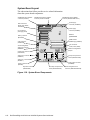
System Features
In addition to the standard features found in a traditional personal computer,
Dell PowerEdge 4100 systems include the following new and/or advanced
features:
• 256 KB (PowerEdge 4100/180 systems) or 512 KB (PowerEdge 4100/200
systems) of cache memory internal to the Pentium Pro module
• 64 MB of 72-bit wide, buffered, extended data output (EDO) main memory,
upgradable to 1024 MB (1 GB)
• Hot-pluggable SCSI backplane supporting up to six hard-disk drives
• Optional, redundant hot-pluggable power supplies
System Overview
1-1
• Error correction code (ECC) feature built into the memory controller on the
system board
• Advanced combination EISA and PCI expansion subsystem
• Five PCI and three EISA expansion-card slots (none shared)
• Integrated VGA-compatible video subsystem attached to the PCI bus, with
1 MB video memory standard
• BIOS in upgradable flash memory attached to the EISA bus
• Integrated super I/O controller attached to the EISA bus, provides a
bidirectional parallel port, two serial ports, and the diskette drive interface
• Integrated ultra-wide and ultra-narrow SCSI controllers
• Integrated server management circuitry that monitors critical system voltages and temperatures, as well as the operation of the system cooling fans
• CD-ROM drive standard in an externally accessible drive bay
• Recessed power and reset buttons to prevent accidental system interruptions
• New quick-test feature in the system diagnostics
All of these features, except the new quick-test feature, are briefly described in
this chapter. (For more information about the Quick Test option in the CD-ROM
based diagnostics, see “Running the System Diagnostics” in Chapter 2.) For a complete
list of system features, see “Technical Specifications” found later in this chapter.
For information about installing the PowerEdge 4100 systems in a rack, see the
“Dell PowerEdge 4100 and 6100 Systems Rack Kit Installation Guide”
(P/N 40722).
1-2
Dell PowerEdge 4100/180 and 4100/200 Systems Service Manual
back of computer
left side
right side
front of computer
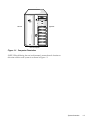
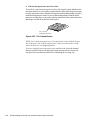
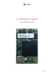
Figure 1-1. Computer Orientation
NOTE: When following the text in this manual, assume that the location or
direction relative to the system is as shown in Figure 1-1.
System Overview
1-3
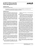
power button and
power-on indicator
reset button
SCSI hard-disk drive
online indicator
SCSI hard-disk drive
fault indicator
diskette-drive access
indicator (typical)
SCSI hard-disk drive
activity indicator
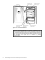
Figure 1-2. Front-Panel Features
CAUTION: To avoid possible data or file structure corruptions, the frontpanel reset button should be used only when restarting the system with a
key combination fails. Before using the reset button to initiate a hardware
reset, close any open application programs and files if possible. If you are
using MS-DOS®, the system can be rebooted by pressing
<Ctrl><Alt><Del>.
1-4
Dell PowerEdge 4100/180 and 4100/200 Systems Service Manual
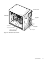
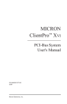
external drive bays (4)
control panel
expansion slots
internal drive
bays (6)
system board
hard-disk drive
security lock
microprocessor sockets
cooling fan connectors (3)
(cooling fans are located
behind the air intake panel)
air intake panel
Figure 1-3. Front/Left Internal View
System Overview
1-5
external drive bays (4)
diskette interface
cable (ultra-narrow)
SCSI interface
connector (ultra-wide)
internal drive bays (6)
SCSI backplane board
SCSI power connector
server
management
connector
control panel connector
power supply (optional)
power supply
Figure 1-4. Back/Right Internal View
1-6
Dell PowerEdge 4100/180 and 4100/200 Systems Service Manual
SMB connector
SCSI connector port
keylock
keylock
power supply
(optional)
video connector
cable strain relief
server-management
serial port connector
parallel port connector
power supply
serial port 2 connector
serial port 1 connector
red LED
mouse connector
keyboard connector
green LED
AC power receptacle SMB connector
SCSI connector port
security cable slot
Figure 1-5. I/O Panel
System Overview
1-7
System Memory
The PowerEdge 4100 systems have a minimum of 64 MB of 72-bit-wide, buffered EDO memory. The system memory capacity can be expanded to 1024 MB
(1 GB) by using combinations of 32- and 128-MB buffered, EDO dual in-line
memory modules (DIMMs) having gold connectors.
The system board has eight 168-pin DIMM sockets. The socket population rules
for the DIMMs are as follows:
• Populate the DIMM sockets in order from DIMM A (upper) to DIMM H
(lower).
• The DIMMs should be obtained from Dell to guarantee compatibility. All
system memory operates at the speed of the slowest DIMM installed.
• DIMMs of both capacities can be installed in the system. However, the
larger-capacity DIMMs should be installed in the top sockets, beginning
with socket DIMM A, with the smaller-capacity DIMMs installed afterwards in order toward socket DIMM H.
The 72-bit wide, buffered EDO DIMMs support the ECC feature, which detects
memory errors and corrects single-bit memory errors. The ECC feature provides more reliable memory and less downtime, and is built into the memory
controller on the system board.
See “DIMMs” in Chapter 4 for information on removing and replacing DIMMs.
Advanced Expansion Subsystem
The computer system offers advanced expansion subsystems that can support a
mixture of traditional EISA expansion cards, Plug and Play ISA expansion cards,
and PCI expansion cards. The EISA Configuration Utility, included with the system,
provides a means of avoiding resource conflicts that might arise from such an
arrangement.
After all legacy cards have been configured with the EISA Configuration Utility,
the system automatically assigns required memory space, IRQ lines, and DMA
channels to any installed Plug and Play ISA expansion cards and PCI expansion
cards the next time the system is rebooted. Chapter 5, “Using the EISA Configuration Utility,” in the Dell PowerEdge 4100/180 and 4100/200 Systems User’s
Guide describes the EISA Configuration Utility and provides instructions for using it
to configure the system.
The eight expansion-card slots include three EISA expansion-card connectors
and five PCI expansion-card connectors. The expansion-card connectors are
located on the system board (see Figure 1-18).
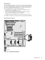
Integrated Server Management
The system board contains integrated server management circuitry that monitors critical system voltages and temperatures, as well as the operation and
speed of the system cooling fans. The integrated server management circuitry
works in conjunction with the Intel LANDesk® Server Management suite.
1-8
Dell PowerEdge 4100/180 and 4100/200 Systems Service Manual
Video Controller
The video subsystem is built into the system board and consists of a high-speed,
high-resolution, VGA-compatible video subsystem. The video controller is connected to the PCI local bus. The standard video subsystem contains 1 MB of
DRAM memory (the video memory size is not upgradable).
Maximum noninterlaced resolutions are 640 x 480 pixels with 16.7 million colors, 800 x 600 pixels with 65,536 colors, and 1024 x 768 pixels with 256 colors.
Integrated SCSI Controllers
A built-in Adaptec 7880 Ultra/Wide SCSI controller provides an ultra-wide fast
SCSI interface via a 68-pin connector on the system board. This SCSI controller
attaches to the PCI bus to provide a high-performance SCSI bus and also controls the six SCSI hard-disk drives in the SCSI hard-disk drive bays. In the
standard Dell PowerEdge 4100 system configuration, the Ultra/Wide SCSI host
adapter on the system board controls the SCSI backplane board. When used in
combination with an optional PowerEdge Expandable RAID Controller host
adapter card, the SCSI backplane board allows you to remove and insert harddisk drives without shutting down the system. External hard-disk drives are not
supported by the built-in SCSI controller.
A built-in Adaptec 7860 Ultra/Narrow SCSI controller provides a SCSI interface via a 50-pin connector to the CD-ROM drive in the externally accessible
drive bay and to any other SCSI drives installed in the other two bays.
SCSI Hard-Disk Drives
Six internal hot-pluggable hard-disk drive bays are located under the externally
accessible drive bays at the front of the computer (see Figure 1-4). These bays can
contain up to six 1- to 1.6-inch-high SCSI hard-disk drives (either fast/wide or ultra
[fast] wide).
NOTES: The externally accessible drive bays at the front of the computer are
normally used for diskette drives, CD-ROM drives, and/or tape drives. Harddisk drives should be installed in the SCSI hard-disk drive bays. For detailed
information about installing externally accessible drives, see Chapter 9, “Installing
Drives in the External Bays,” in the Dell PowerEdge 4100/180 and 4100/200 Systems Installation and Troubleshooting Guide. For detailed information about
installing SCSI hard-disk drives, see Chapter 10, “Installing Drives in the Internal
Bays,” in the Installation and Troubleshooting Guide.
Dell supports the drives it furnishes.
SCSI Configuration Guidelines
Although SCSI devices are installed essentially the same way as other devices,
their configuration requirements are different. To configure your SCSI subsystem, follow the general guidelines offered in the following subsections.
System Overview
1-9
SCSI ID Numbers
Each device attached to the 7860 Ultra/Narrow SCSI host adapter must have a
unique SCSI ID number from 0 to 7. For additional SCSI addressing information, see Chapter 10, “Installing Drives in the Internal Bays,” in the Installation
and Troubleshooting Guide.
When narrow SCSI devices are shipped from Dell, the default SCSI ID numbers
are assigned as follows:
• The computer’s built-in Ultra/Narrow SCSI host adapter is configured
through the BIOS as SCSI ID 7.
• A SCSI CD-ROM drive (installed in an externally accessible drive bay) is
configured as SCSI ID 5.
• A SCSI tape drive (if installed) is configured as SCSI ID 6.
NOTE: There is no requirement that SCSI ID numbers be assigned sequentially or
that devices be attached to the cable in order by ID number.
Devices attached to the Ultra/Wide SCSI host adapter need no ID settings or termination; ID settings and termination are handled automatically by the SCSI
backplane.
Device Termination
SCSI logic requires that termination be enabled for the two devices at opposite
ends of the SCSI chain and disabled for all devices in between. Therefore,
regardless of whether you are installing internal or external devices, use the following guidelines:
• A single SCSI device (such as the standard CD-ROM drive) is terminated.
• If two or more SCSI devices are installed, connect the devices as follows:
—
Attach one of the devices to the end connector on the SCSI cable, and leave the
terminator enabled on that device.
—
The other end of the SCSI cable connects to the computer’s built-in Ultra/Narrow
SCSI host adapter or to an optional SCSI host adapter card, which needs no
termination.
—
Disable the terminators on all other devices you attach to the cable.
The standard SCSI CD-ROM drive is configured as the last device on the SCSI
cable. Therefore, any additional devices attached to the cable should have their
terminators disabled.
See the documentation provided with the SCSI device for information on disabling the device’s terminator.
1-10
Dell PowerEdge 4100/180 and 4100/200 Systems Service Manual
System Unit
The following subsections provide service-related information about the system
unit.
System Power Supply
The 500-W system power supply can operate from an AC power source of 90 to
265 VAC at 50 or 60 Hz. When the power-supply paralleling board is installed,
the power supplies are hot-pluggable. When the red LED on the power supply is
lit (except during power-up), it indicates that the power supply has failed (see
Figure 1-5). When the green LED is lit, it indicates that +5 VDC is on. The system power supply provides the DC operating voltages and currents listed in
Table 1-1.
NOTE: The power supply produces DC voltages only under its loaded condition. Therefore, when you measure these voltages, the DC power connectors
must be connected to their corresponding power input connectors on the system
board or drives.
.
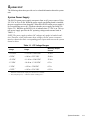
Table 1-1. DC Voltage Ranges
Voltage
Range
Maximum Output
Current 1
+3.3 VDC
+3.135 to +3.465 VDC
15.0 A
+5 VDC
+4.90 to +5.25 VDC
50.0 A
+12 VDC
+11.40 to +12.60 VDC
25.0 A
–12 VDC
–10.80 to –13.20 VDC
0.3 A
–5 VDC
–4.50 to –5.50 VDC
0.3 A
+5 VFP 2
+4.85 to +5.36 VDC
0.25 A
1
Maximum continuous DC output power shall not exceed 500 W.
2
VFP (volts flea power) — sometimes called “standby power.”
System Overview
1-11
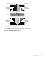
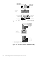
Pin Assignments for the DC Power Connectors (Nonredundant Systems)
The power-supply output voltages for nonredundant systems can be measured
at the connectors on the back of the power supply (P1, P2, P3, P4, and P5) or at
the connectors on the power connector panel (J11, J12, J13, J14, and J15). The
following illustrations show both sets of connectors.
P2
P1
P5
P4
P3
Figure 1-6. Power Supply Connectors
J12 (P2)
J11 (P1)
J15 (P5)
J14 (P4)
J13 (P3)
Figure 1-7. Power Connector Panel
1-12
Dell PowerEdge 4100/180 and 4100/200 Systems Service Manual
+5 VDC (red)
+5 VDC (red)
–5 VDC (white)
+5 VDC (red)
common (black)
+5 VDC (red)
common (black)
+5 VDC (red)
common (black)
+3.3 VDC (orange)
PSON# 1 (gray)
+3.3 VDC (orange)
13 14 15
16 17 18 19
20 21 22 23 24
J11 (P1)
1
2
3
4
5
6
7
8
9
10 11 12
+5 VDC (red)
common (black)
+3.3 VDC (orange)
+3.3 VDC sense (orange)
+5 VDC sense (red)
common (black)
–sense (black)
common (black)
PWRGOOD 2 (orange)
+5 VFP (purple)
-12 VDC (blue)
+12 VDC (yellow)
1
Pin 13 — PSON# should measure between +4 and +5 VDC except when the power button on the front
panel is pressed, taking PSON# to its active-low state.
2
Pin 5 — PWRGOOD should measure between +4 and +5 VDC when the power supply is on and operating to indicate that all power-supply output voltages are within the ranges specified in Table 1-1.
Figure 1-8. DC Power Connector J11 (P1)
System Overview
1-13
+5 VDC (red)
common (black)
common (black)
common (black)
common (black)
common (black)
common (black)
common (black)
+5 VDC (red)
10 11 12
13 14 15
16 17 18
J12 (P2), J13 (P3),
J14 (P4)
1
2
3
4
5
6
7
8
9
+3.3 VDC (orange)
+5 VDC (red)
+12 VDC (yellow)
+3.3 VDC (orange)
+3.3 VDC (orange)
+12 VDC (yellow)
+5 VDC (red)
+5 VDC (red)
+5 VDC (red)
Figure 1-9. DC Power Connectors J12 (P2), J13 (P3), and J14 (P4)
+SW1
+12 VDC (red)
+3.3 VDC (orange)
Fail LED cathode (red)
Good LED cathode (green)
6
7
1
2
8
9 10
J15 (P5)
3
4
5
Good LED anode (green)
Fail LED anode (red)
+5 VDC (red)
+FAN_TACH (gray)
+SW1
Figure 1-10. DC Power Connector J15 (P5)
1-14
Dell PowerEdge 4100/180 and 4100/200 Systems Service Manual
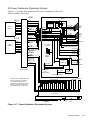
DC Power Distribution (Nonredundant System)
Figures 1-11 provides information about DC power distribution for the
nonredundant PowerEdge 4100 system.
P1
P1–5
power
supply # 1
NRLED
PWRGOOD
PSON#
+5 VFP
+5 VDC
–5 VDC
+12 VDC
–12 VDC
+3.3 VDC
PSON#
+5 VFP
+5 VDC
–5 VDC
+12 VDC
–12 VDC
+3.3 VDC
P2
+12 VDC
+5 VDC
+3.3 VDC
system board
keyboard
controller
power
management
logic
battery
RTC/
NVRAM
PWRGOOD
PSON#
+5 VFP
+5 VDC
–5 VDC
+12 VDC
–12 VDC
+3.3 VDC
P3
PCI4
through
PCI8
+5 VDC
–5 VDC
+12 VDC
–12 VDC
EISA1
through
EISA3
battery (+3 VDC)
+3.3 VDC
+5 VFP
PWRGOOD
main memory
sockets
+12 VDC
+5 VDC
+3.3 VDC
+3.3 VDC
+5 VDC
+12 VDC
–12 VDC
+5 VFP to SCSI backplane
+12 VDC
DDBP
+12 VDC
+12 VDC
+5 VDC
+12 VDC
DIMM A
through
DIMM H
FD1–4
FAN1
FAN2
FAN3
fuse
+12 VDC
+5 VDC
processor
core
regulator (2)
+3.3 VDC
power
connector
panel
REMOTE
+5 VDC
MOUSE
+5 VDC
KEYBOARD
core VCC (+2.1 to +3.5 VDC)
PROCESSOR1
and
PROCESSOR2
GTL
regulator
+1.5 VDC
P6 signal terminators
NOTE: A server management cable
(16-pin) carries the +5 VFP from
the system board to the SCSI
backplane. The control panel cable
(30-pin) carries the +5 VFP from
the backplane to the control panel.
SCSI backplane
(six drive bays)
6
5
4
3
CD-ROM FLOPPY
2
1
control panel
+5 VFP from SCSI backplane
reset
3 X 6 LEDs
on/off
power-on
LED
speaker
Figure 1-11. Power Distribution (Nonredundant System)
System Overview
1-15
Pin Assignments for the DC Power Connectors (Redundant
Systems)
The power-supply output voltages for redundant systems can be measured at the
connectors on the power-supply paralleling board (PWR1, PWR2, PWR3,
PWRSCSI, and PWRFD) or at the connectors on the end of the wire bundles
extending from these connectors (PWR1, PWR2, PWR3, DDBP, and
FD1–FD4).
PWR1
PWRFD
(FD1–FD4)
PWR2
PWR3
diagnostics port
PWRSCSI
(DDBP)
Figure 1-12. Power-Supply Paralleling Board Connectors
1-16
Dell PowerEdge 4100/180 and 4100/200 Systems Service Manual
NC_3INH
common (black)
+3.3 VDC sense (orange)
-3.3 VDC sense (black)
POWER_GOOD (gray)
FAN_TACH (gray)
common (black)
NC_NRLED
+5 VFP (violet)
10 11 12
13 14 15
16 17 18
PWR1
1
2
3
4
5
6
7
8
9
BAT_V (gray)
-12 VDC (blue)
PRES_DET (gray)
-5 VDC (white)
NC_+12 sense
PWR_STAT_BIT (gray)
I 2C_SDA (gray)
+5 VDC sense (red)
I 2C_SCL (gray)
Figure 1-13. DC Power Connector PWR1
common (black)
+3.3 VDC (orange)
+3.3 VDC (orange)
common (black)
common (black)
+12 VDC (yellow)
+3.3 VDC (orange)
common (black)
common (black)
+12 VDC (yellow)
11 12 13
14 15 16 17
18 19 20
PWR2,
PWR3
1
+5 VDC (red)
common (black)
+5 VDC (red)
common (black)
+5 VDC (red)
2
3
4
5
6
7
8
9
10
common (black)
+5 VDC (red)
common (black)
+5 VDC (red)
common (black)
Figure 1-14. DC Power Connector PWR2 and PWR3
System Overview
1-17
common (black)
common (black)
common (black)
common (black)
common (black)
common (black)
common (black)
8
10 11 12 13 14
9
PWRSCSI
(DDBP)
1
2
3
4
5
6
7
+12 VDC (yellow)
+12 VDC (yellow)
+5 VDC (red)
+5 VDC (red)
+12 VDC (yellow)
+12 VDC (yellow)
+5 VDC (red)
Figure 1-15. DC Power Connector PWRSCSI (DDBP)
+12 VDC (yellow)
common (black)
common (black)
+5 VDC (red)
5
6
7
82
1
2
3
41
PWRFD
(FD1–FD4)
+5 VDC (red)
common (black)
common (black)
+12 VDC (yellow)
1
Wires 1 through 4 are connected to FD1 and FD2.
2
Wires 5 through 8 are connected to FD3 and FD4.
Figure 1-16. DC Power Connector PWRFD (FD1–FD4)
1-18
Dell PowerEdge 4100/180 and 4100/200 Systems Service Manual
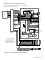
DC Power Distribution (Redundant System)
Figures 1-17 provides information about DC power distribution for the redundant PowerEdge 4100 system.
PWR1
P1–5
power
supply # 1
POK
PSON#
+5 VFP
+5 VDC
–5 VDC
+12 VDC
–12 VDC
+3.3 VDC
BATV
PWRGOOD
PSON#
+5 VFP
+5 VDC
–5 VDC
+12 VDC
–12 VDC
+3.3 VDC
PWR2
P1–5
power
supply # 2
PSON#
+5 VFP
+5 VDC
–5 VDC
+12 VDC
–12 VDC
+3.3 VDC
+12 VDC
+5 VDC
+3.3 VDC
keyboard
controller
system board
power
management
logic
battery
RTC/
NVRAM
BATV
PWRGOOD
PSON#
+5 VFP
+5 VDC
–5 VDC
+12 VDC
–12 VDC
+3.3 VDC
main memory
sockets
+5 VDC
–5 VDC
+12 VDC
–12 VDC
EISA1
through
EISA3
+12 VDC
+12 VDC
DIMM A
through
DIMM H
+12 VDC
+5 VDC
PWRFD
(FD1–4)
+12 VDC
+5 VDC
REMOTE
+5 VFP to SCSI backplane
+12 VDC
PWRSCSI
(DDBP)
power-supply
paralleling board
PCI4
through
PCI8
battery (+3 VDC)
+3.3 VDC
+5 VFP
PWRGOOD
PWR3
+12 VDC
+5 VDC
+3.3 VDC
+3.3 VDC
+5 VDC
+12 VDC
–12 VDC
FAN1
FAN2
FAN3
fuse
processor
core
regulator (2)
+3.3 VDC
+5 VDC
MOUSE
+5 VDC
KEYBOARD
core VCC (+2.1 to +3.5 VDC)
PROCESSOR 1
and
PROCESSOR 2
GTL
regulator
+1.5 VDC
P6 signal terminators
NOTE: A server management cable
(16-pin) carries the +5 VFP from
the system board to the SCSI
backplane. The control panel cable
(30-pin) carries the +5 VFP from
the backplane to the control panel.
SCSI backplane
(six drive bays)
6
5
4
3
CD-ROM FLOPPY
2
1
control panel
+5 VFP from SCSI backplane
reset
3 X 6 LEDs
on/off
power-on
LED
speaker
Figure 1-17. Power Distribution (Redundant System)
System Overview
1-19
System Board Layout
The subsections that follow provide service-related information
about the system board components.
diskette/tape drive interface
connector (FLOPPY)
Ultra/Narrow SCSI host adapter
connector (SCSI2 CD-ROM)
Ultra/Wide SCSI host adapter
connector (BACKPLANE SCSI1)
power supply
connector (POWER2)
EISA connectors
(EISA1 [top], EISA2,
and EISA3)
power supply
connector (POWER1)
PCI connectors
(PCI4 [top]–PCI8)
front of
system board
battery connector
(BATTERY)
DIMM sockets
(DIMM A [top]–DIMM H)
video connector
(MONITOR)
fan connectors
(FAN1, FAN2, FAN3)
server-management
serial port connector
(REMOTE)
speed and configuration
jumpers
parallel port connector
(PARALLEL)
serial port 2 connector
(SERIAL2)
primary microprocessor
socket (PROCESSOR1)
serial port 1 connector
(SERIAL1)
power supply connector
(POWER3)
mouse connector
(MOUSE)
keyboard connector
(KEYBOARD)
secondary microprocessor
socket (PROCESSOR2)
Figure 1-18. System Board Components
1-20
Dell PowerEdge 4100/180 and 4100/200 Systems Service Manual
server-management bus
connector (SMB BACKPLANE)
Main Memory
The eight DIMM sockets on the system board can accommodate combinations
of 32- and 128-MB DIMMs up to a total memory capacity of 1024 MB (1 GB).
The system is shipped with high-speed (60-ns) 3.3-V EDO DIMMs installed.
When reinstalling DIMMs, use the following guidelines:
• Install a DIMM in socket DIMM A before socket DIMM B, in socket
DIMM B before socket DIMM C, and so on.
• If you are installing DIMMs of different sizes, install them in order of
decreasing capacity, beginning with socket DIMM A.
• DIMMs need not be installed in pairs, but gold connectors are required.
See “DIMMs” in Chapter 4 for information on removing and replacing DIMMs.
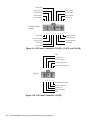
System Board Jumpers
jumpered
unjumpered
Figure 1-19. System Board Jumpers
System Overview
1-21
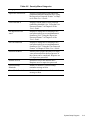
Table 1-2. Jumper Descriptions
Jumper
Description
Default Setting
EISA
EISA Configuration Utility
Not installed (utility settings are
retained at system boot)
VGA
Integrated video controller
Installed (controller is enabled)
PASSWD
Password enable/disable
Installed (password feature
enabled)
CRDBIOS
Reserved
Not installed (reserved; do not
change)
RSRVD2
RSRVD1
Reserved
Not installed (reserved; do not
change)
200MHZ
Microprocessor speed
Installed only if the microprocessor’s internal speed is
200 MHz
180MHZ
Microprocessor speed
Installed only if the microprocessor’s internal speed is
180 MHz
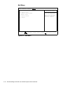
Interrupt Assignments
Table 1-3. Interrupt Assignments
1-22
IRQ Line
Used/Available
IRQ0
Generated by system timer
IRQ1
Generated by keyboard controller to indicate that keyboard’s
output buffer is full
IRQ2
Generated internally by interrupt controller to enable IRQ8
through IRQ15
IRQ3
and
IRQ4
Generated by super I/O controller to indicate that device connected to corresponding serial port requires service (IRQ3 for
COM2 or COM4; IRQ4 for COM1 or COM3)
IRQ5
Available for use by expansion card unless this IRQ line is used by
secondary parallel port
IRQ6
Generated by super I/O controller to indicate that diskette drive
requires service
IRQ7
Generated by super I/O controller to indicate that device connected to parallel port requires service
IRQ8
Generated by keyboard controller for each tick of RTC
IRQ9
Available for use by expansion card
Dell PowerEdge 4100/180 and 4100/200 Systems Service Manual
Table 1-3. Interrupt Assignments (continued)
IRQ Line
Used/Available
IRQ10
Available for use by expansion card
IRQ11
Available for use by expansion card
IRQ12
Generated by keyboard controller to indicate that mouse’s output
buffer is full
IRQ13
Generated by math coprocessor to indicate coprocessor error
IRQ14
Available for use by expansion card
IRQ15
Available for use by expansion card
DMA Channel Assignments
Table 1-4. DREQ Line Assignments
DREQ Line
Used/Available
DREQ0
Available
DREQ1
Available
DREQ2
Generated by super I/O controller to initiate DMA cycle for
attached diskette drive
DREQ3
Available
DREQ4
Generated by bus controller chip to activate second DMA
controller
DREQ5
Available
DREQ6
Available
DREQ7
Available
System Overview
1-23
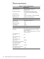
Technical Specifications
Table 1-5. Technical Specifications
Microprocessor
Microprocessor type . . . . . . . . single or dual Intel Pentium Pro
microprocessors
Microprocessor speed. . . . . . . 200 MHz internal (66 MHz external)
or 180 MHz internal (60 MHz external)
First-level cache . . . . . . . . . . . 16 KB
Second-level cache . . . . . . . . . 256 KB for 180 MHz; 512 KB for 200 MHz
Math coprocessor . . . . . . . . . . internal to the microprocessor
System Information
System chip set. . . . . . . . . . . . Intel Natoma 82440FX set
Data bus width . . . . . . . . . . . . 64 bits
Address bus width . . . . . . . . . 32 bits
Flash EPROM. . . . . . . . . . . . . 4 Mbits
Expansion Bus
Bus types . . . . . . . . . . . . . . . . PCI and EISA
Bus speed . . . . . . . . . . . . . . . . PCI: 30 MHz (180/60 processor); 33 MHz
(200/66 processor);
EISA: 7.5 MHz (180/60 processor); 8.33 MHz
(200/66 processor)
PCI expansion-card
connectors. . . . . . . . . . . . . . . . five
EISA expansion-card
connectors. . . . . . . . . . . . . . . . three
EISA expansion-card
connector size . . . . . . . . . . . . . 198 pins
EISA expansion-card connector
data width (maximum) . . . . . . 32 bits
PCI expansion-card
connector size . . . . . . . . . . . . . 120 pins
PCI expansion-card connector
data width (maximum) . . . . . . 32 bits
1-24
Dell PowerEdge 4100/180 and 4100/200 Systems Service Manual
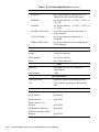
Table 1-5. Technical Specifications (continued)
System Clocks
System clock . . . . . . . . . . . . . . 60 or 66 MHz (matches external processor bus
speed)
Diskette/communications
ports . . . . . . . . . . . . . . . . . . . . 24 MHz from the system clock
Memory
Architecture . . . . . . . . . . . . . . 72-bit, noninterleaved
DIMM sockets . . . . . . . . . . . . eight
DIMM capacities . . . . . . . . . . 32 and 128 MB, EDO mode
Standard RAM . . . . . . . . . . . . 64 MB
Maximum RAM . . . . . . . . . . . 1024 MB (1 GB)
BIOS address . . . . . . . . . . . . . F000:0000h–F0000:FFFFh
Drives
Externally accessible bays . . . four 5.25-inch bays for half-height diskette
drives, tape drives, or CD-ROM drives (one
bay for a 3.5-inch diskette drive and one bay
for a CD-ROM [standard])
Internally accessible bays . . . . six 1- to 1.6-inch-high SCSI hard-disk drives,
hot-pluggable with an optional PowerEdge
Expandable RAID Controller host adapter card
System Board Connectors
Externally accessible:
Serial (DTE) . . . . . . . . . . . two 9-pin connectors; 16550-compatible
(UART)
Server Management
(serial) . . . . . . . . . . . . . . . . one 9-pin connectors; modem port for
embedded server management
Parallel . . . . . . . . . . . . . . . one 25-hole connector (bidirectional)
Video . . . . . . . . . . . . . . . . . one 15-hole connector (on system board or
add-in video card)
PS/2-style keyboard . . . . . one 6-pin mini-DIN
PS/2-compatible mouse. . . . one 6-pin mini-DIN
Internally accessible:
Diskette drive . . . . . . . . . . one 34-pin connector
Fan . . . . . . . . . . . . . . . . . . three 3-pin connectors
System Overview
1-25
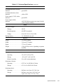
Table 1-5. Technical Specifications (continued)
System Board Connectors (continued)
POWER1 . . . . . . . . . . . . . one 18-pin connector: standby power, I2 C,
PWRGOOD, and miscellaneous power
POWER2 . . . . . . . . . . . . . one 20-pin connector: +3.3 VDC, +5 VDC, or
+12 VDC
POWER3 . . . . . . . . . . . . . one 20-pin connector: +3.3 VDC, +5 VDC, or
+12 VDC
BACKPLANE SCSI1. . . . one 68-pin connector, ultra-wide (fast), to
SCSI backplane
SCSI2 CD-ROM. . . . . . . . one 50-pin connector, ultra-narrow, to
CD-ROM
SMB BACKPLANE. . . . . one 16-pin connector (server management) to
SCSI backplane
SCSI Backplane Connectors
SCSI hard-disk drive connection
sockets . . . . . . . . . . . . . . . . . . six 80-pin connectors
SCSI controller . . . . . . . . . . . . one 68-pin connector
Power . . . . . . . . . . . . . . . . . . . one 14-pin connectors
Video
Video type. . . . . . . . . . . . . . . . embedded PCI (see User’s Guide for
specifications)
Video memory . . . . . . . . . . . . 1 MB
Key Combinations
<Ctrl><Alt><Del> . . . . . . . . . . . . reboots the system (if running MS-DOS)
<F2> . . . . . . . . . . . . . . . . . . . . . . . . starts System Setup program (during POST
only)
Controls and Indicators
Reset control. . . . . . . . . . . . . . push button
Power control . . . . . . . . . . . . . push button
Power indicator. . . . . . . . . . . . green LED
Diskette drive access
indicator . . . . . . . . . . . . . . . . . green LED
CD-ROM busy indicator . . . . green LED
SCSI hard-disk drive online
indicator . . . . . . . . . . . . . . . . . green LED
1-26
Dell PowerEdge 4100/180 and 4100/200 Systems Service Manual
Table 1-5. Technical Specifications (continued)
Controls and Indicators (continued)
SCSI hard-disk drive activity
indicator . . . . . . . . . . . . . . . . . green LED
SCSI hard-disk drive fault
indicator . . . . . . . . . . . . . . . . . yellow LED
Power-supply 5-VDC online
indicator . . . . . . . . . . . . . . . . . green LED
Power-supply failure
indicator . . . . . . . . . . . . . . . . . red LED (flashes at power-on; stays lit in the
event of a power failure)
Power
DC power supply:
Wattage . . . . . . . . . . . . . . . 500 W
Heat dissipation. . . . . . . . . 600 BTUs (nominal)
Voltage . . . . . . . . . . . . . . . 90 to 265 VAC at 50 or 60 Hz
Backup battery . . . . . . . . . . . . 3-V CR2450N coin cell
Physical
Height . . . . . . . . . . . . . . . . . . . 52.5 cm (21 inches)
Width. . . . . . . . . . . . . . . . . . . . 39.4 cm (15.75 inches)
Depth. . . . . . . . . . . . . . . . . . . . 57.5 cm (23 inches)
Weight . . . . . . . . . . . . . . . . . . 45 kg (100 lb) or more, depending on options
installed
Environmental
Temperature:
Operating . . . . . . . . . . . . . 10° to 35°C (50° to 95°F)
Storage . . . . . . . . . . . . . . . –40° to 65°C (–40° to 149°F)
Relative humidity . . . . . . . 8% to 80% (noncondensing)
Maximum vibration:
Operating . . . . . . . . . . . . . 0.25 G at 3 to 200 Hz for 30 min
Storage . . . . . . . . . . . . . . . 0.5 G at 3 to 200 Hz for 30 min
Maximum shock:
Operating . . . . . . . . . . . . . half-sine wave form: 50 G for 2 ms
Storage . . . . . . . . . . . . . . . half-sine wave form: 110 G for 2 ms;
square wave form: 27 G for 15 ms
System Overview
1-27
Table 1-5. Technical Specifications (continued)
Environmental (continued)
Altitude:
Operating . . . . . . . . . . . . . –16 to 3048 m (–50 to 10,000 ft)
Storage . . . . . . . . . . . . . . . –16 to 10,600 m (–50 to 35,000 ft)
z
1-28
Dell PowerEdge 4100/180 and 4100/200 Systems Service Manual
Chapter 2
Basic Troubleshooting
This chapter describes basic troubleshooting procedures that can help you
diagnose a computer system problem. These procedures can often reveal the
source of a problem or indicate the correct starting point for troubleshooting the
system. (A brief explanation of how to load and start the system diagnostics is
located near the end of this chapter.) Dell recommends that you perform the following procedures in the order they are presented in this manual.
Initial User Contact
When you first contact a user who has a problem, ask the user to describe the
problem and the conditions under which it occurs. A verbal description can
often indicate the cause of a problem or else the appropriate troubleshooting
procedure to use. After the user describes the problem, follow these steps:
1. Ask the user to back up any data on the hard-disk drive if the system’s
condition permits.
Appendix C, “Maintaining the System,” in the User’s Guide provides information about backing up data.
2. Ask the user to try to duplicate the problem by repeating the operations
he or she was performing at the time the problem occurred.
Can the user duplicate the problem?
Yes. Proceed to step 3.
No. Proceed to the next section, “External Visual Inspection.”
3. Observe the user to determine if he or she is making an error, such as
typing an incorrect key combination or entering a command
incorrectly.
Is the problem a result of user error?
Yes. Instruct the user in the proper procedure, or direct him or her to the
appropriate user documentation for the correct procedure.
No. Proceed to the next section, “External Visual Inspection.”
Basic Troubleshooting
2-1
External Visual Inspection
The external visual inspection consists of a quick inspection of the exterior of
the computer, the monitor, the keyboard, any peripherals, and cables. While performing the visual inspection, make any necessary corrections. To perform the
external visual inspection, follow these steps:
1. Turn off the computer, the monitor, and all peripherals.
2. Verify that all power cables are properly connected to the computer, the
monitor and peripherals, and their power sources.
3. Verify that the keyboard and mouse interface cables are firmly
attached to the proper connectors on the back of the computer.
For a PS/2-compatible mouse, the keyboard and mouse interface cable connectors are identical except for their labels (see Figure 1-5).
For a serial mouse, the mouse interface cable must be attached to one of the
serial port connectors, and its captive screws must be secure enough to
ensure a firm connection.
4. Verify that any devices attached to the serial and parallel port connectors are properly connected.
Each of the serial and parallel interface cables must be attached to an appropriate connector on the back of the computer as well as to the interface
connector on the device. The captive screws that secure these connectors at
each end of the interface cable must be secure enough to ensure a firm
connection.
5. Verify that the video interface cable is firmly attached to the connector
on the I/O panel and to the connector on the back of the monitor.
For proper connection of the video interface cable, see the documentation
for the monitor.
6. Inspect all external monitor controls for any obvious damage or
improper settings.
For proper settings of the video monitor controls, see the documentation for
the monitor.
7. Inspect the keyboard to ensure that no keys are sticking.
If one or more keys are sticking, it may be necessary to replace the
keyboard.
8. Inspect the exterior of the computer, including all controls and indicators, and all user-accessible data storage devices for any signs of
physical damage.
Does the inspection reveal any problems?
Yes. Proceed to the appropriate procedure in Chapter 4, “Removing and
Replacing Parts.”
No. Proceed to the next section, “Observing the Boot Routine.”
2-2
Dell PowerEdge 4100/180 and 4100/200 Systems Service Manual
Observing the Boot Routine
After you have performed an external visual inspection as described in the previous section, you should boot the system and, while the boot routine is
running, observe the system for any indications of problems.
NOTE: Most of the steps in this procedure require observation of system functions and indications, some of which can occur simultaneously. It may be
necessary to reboot the system several times in order to complete all of these
steps.
To observe problem indications during the boot routine, follow these steps:
1. If the system is off, turn on all peripherals and the computer. Insert the
Dell Server Assistant CD into the CD-ROM drive. Press the reset button or <Ctrl><Alt><Del> to reboot the system.
2. Check the power supply fans.
Do the fans run normally?
NOTE: The center fan is normally off, unless another fan has failed or is
unplugged, or the temperature of the computer is too high.
Yes. Proceed to step 3.
No. Troubleshoot the system power supply.
3. Watch the Num Lock, Caps Lock, and Scroll Lock indicators on the
upper-right corner of the keyboard. After all three indicators flash
momentarily, and following a long pause (approximately 30 seconds),
the Num Lock indicator should light up and remain on.
Do these indicators flash on and off within approximately 10 seconds after
the boot routine starts?
Yes. Proceed to step 4.
No. Troubleshoot the system power supply. If the troubleshooting procedure
indicates that the system power supply is operational, troubleshoot the
memory.
4. During the boot routine, observe the computer for any of the following:
• Beep codes: A beep code is a series of beeps that indicates an error condition. If the system emits a beep code, see Table 3-1.
NOTE: The system beeps once during the boot routine. This single beep is
normal and is not a beep code.
• System error messages: These messages can indicate problems or provide status information. If a system error message is displayed, see
Table 3-2.
• Diskette-drive and hard-disk drive activity indicators: These indicators
light up in response to data being transferred to or from the drives. If
either of these indicators fails to light up during the boot routine, troubleshoot the diskette drive or hard-disk drive subsystem, as appropriate.
Basic Troubleshooting
2-3
5. Observe the monitor screen for the Dell Server Assistant Menu.
Does the menu appear?
Yes. See “Running the System Diagnostics” found later in this chapter.
No. Proceed to the next section, “Internal Visual Inspection.”
Internal Visual Inspection
CAUTION: Before you proceed with the internal visual inspection
described in this section, ensure that the user has saved all open files and
exited all open application programs if possible.
A simple visual inspection of a computer’s interior hardware can often lead to the
source of a problem, such as a loose expansion card, cable connector, or mounting screw.
When you perform the visual inspection, refer to “System Features” in Chapter 1 to locate
components in the inspection procedure.
To perform the internal visual inspection, follow these steps:
1. Turn off the system, including any attached peripherals, and disconnect
all the AC power cables from their power sources.
2. Remove the left computer cover.
3. Verify that all DIMMs and expansion cards as well as the microprocessor(s) and battery are fully seated in their sockets or connectors.
WARNINGS: The microprocessor can get extremely hot. Be sure the
chip has had sufficient time to cool before you touch it.
To maintain proper air flow and prevent the system from overheating, each power supply bay must have either a power supply or the
power closeout panel installed.
To ensure that the chips are fully seated in their sockets, press firmly on the
top of each chip.
To reseat a microprocessor, first remove it from its socket and then reinstall
it as described in “Microprocessor and Heat Sink” in Chapter 4.
To reseat a DIMM, remove it from its socket and reinstall it as described in
“DIMMs” in Chapter 4.
If you need to reseat an expansion card, use a 1/4-inch nut driver to remove
the screw that secures the card-mounting bracket. Grasp the card by its top
corners, and carefully pull it out of its connector. Reinsert the card in its
connector, and carefully push it in until fully seated. Then reinstall the cardmounting bracket’s retaining screw.
2-4
Dell PowerEdge 4100/180 and 4100/200 Systems Service Manual
4. Verify that all jumpers are set correctly.
For information about these jumpers, see “System Board Jumpers” in Chapter 1.
5. Check all cable connectors inside the computer to verify that they are
firmly attached to their appropriate connectors.
6. Reinstall the computer cover.
7. Reconnect the computer and any attached peripherals to their power
sources, and turn them on.
Does the problem appear to be resolved?
Yes. No further steps are necessary. Terminate the procedure.
No. Proceed to the next section, “Eliminating Resource Conflicts,” and to
“Getting Help” found later in this chapter.
Eliminating Resource Conflicts
Devices within the computer may require dedicated memory spaces, interrupt
levels, or DMA channels, all of which must be allocated during installation of
the devices. Because a device may be installed at a different time, it is possible
that the same resource is assigned to two or more devices.
Resource conflicts can result in disorderly or erratic system operation or failure
of the system to operate at all. If you suspect that resource conflicts might exist,
check the system and reassign the resources as necessary.
Running the System Diagnostics
The system diagnostics (included on the Dell Server Assistant CD) contains
tests that aid in troubleshooting all major components of the computer system.
To start the diagnostics, insert the CD into the CD-ROM drive, and then press
the reset button on the computer.
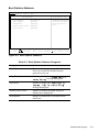
Restarting the computer causes the Dell Server Assistant logo screen to appear
on the monitor screen, followed by a screen containing icons of the options
available. Selecting the Run System Utilities icon brings up a screen with the
diagnostics icon. Before the Dell Server Assistant loads, a program tests the
portion of main memory (RAM) required for loading the diagnostics. If a main
memory error is detected, a message telling you which DIMM has failed
appears on the screen.
Basic Troubleshooting
2-5
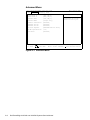
If no errors are found in main memory, and the Dell Server Assistant loads,
select the Run System Utilities icon. Then select the Run System Diagnostics
icon by pressing <Enter>. The Diagnostics Menu appears, allowing you to
choose the following options or exit to MS-DOS:
• Run All Tests — Runs all tests for a thorough check of the system
• Run Quick Tests — Runs selected tests from all test groups to quickly locate
a failure or to indicate where further testing is needed to isolate a failure
• Run Specific Tests — Tests a particular area or subsystem
Getting Help
If none of the troubleshooting procedures in this chapter or the tests in the
system diagnostics reveals the source of the problem or leads to the proper troubleshooting steps for determining the source of the problem, call Dell for
technical assistance. For instructions, see Chapter 11, “Getting Help,” in the
Installation and Troubleshooting Guide.
2-6
Dell PowerEdge 4100/180 and 4100/200 Systems Service Manual
Chapter 3
Beep Codes and Error Messages
This chapter describes beep codes and system error messages that can occur
during system start-up or, in the case of some failures, during normal system
operation. The tables in this chapter list faults that can cause a beep code or system error message to occur and the probable causes of the fault in each case.
If a faulty system does not emit beep codes or display system error messages to
indicate a failure, you should use the CD-based diagnostics to run the appropriate tests to help isolate the source of the problem. See “Running the System
Diagnostics” in Chapter 2.
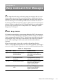
POST Beep Codes
If the monitor cannot display error messages during the POST, the system may
emit a series of beeps that identifies the problem or that can help you identify a
faulty component or assembly. Table 3-1 lists the beep codes that may be generated during the POST. Most beep codes indicate a fatal error that prevents the
system from completing the boot routine until the indicated condition is
corrected.
When the system emits a beep code, record the code and then find it in
Table 3-1. If the table does not lead to the source of the problem, run the appropriate tests in the CD-based diagnostics to assist in troubleshooting the problem.
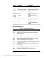
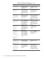
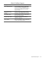
Table 3-1. Beep Codes
Beep Code
Error
Probable Causes
1-2
Invalid expansion-card
ROM checksum
Improperly seated expansion card, or system needs to
be rebooted.
1-2-2-3
Invalid BIOS ROM
checksum
Corrupted BIOS firmware
or defective system board.
1-3-1-1
DRAM refresh failure
Defective DIMMs or system
board. Reseat DIMMs or
replace system board.
1-3-1-3
Keyboard controller
error
Defective DIMMs or system
board. Reseat DIMMs or
replace system board.
Beep Codes and Error Messages
3-1
Table 3-1. Beep Codes (continued)
3-2
Beep Code
Error
Probable Causes
1-3-3-1
No DIMM memory
installed
Defective DIMMs or system
board. Reseat DIMMs or
replace system board.
1-3-4-1
DRAM failure
Defective DIMMs or system
board. Reseat DIMMs or
replace system board.
1-3-4-3
DRAM failure
Defective DIMMs or system
board. Reseat DIMMs or
replace system board.
1-4-1-1
DRAM failure
Defective DIMMs or system
board. Reseat DIMMs or
replace system board.
1-4-2-1
CMOS failure
Defective system board.
1-4-3-1
Memory controller or
DIMM failure
Defective DIMMs or system
board. Reseat DIMMs or
replace system board.
2-2-3-1
Unexpected interrupt
Improperly seated expansion card, or system needs to
be rebooted.
3-2-2-1
4-2-4-4
Gate A20 failure
Defective system board.
4-2-4-3
Keyboard controller
error
Defective DIMMs or system
board. Reseat DIMMs or
replace system board.
Dell PowerEdge 4100/180 and 4100/200 Systems Service Manual
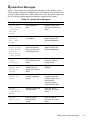
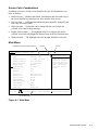
System Error Messages
Table 3-2 lists system error messages that can appear on the monitor screen.
These messages can help you find the source of a problem. Some of these error
messages indicate fatal errors. When a fatal error occurs, the system cannot usually be rebooted until an appropriate hardware change has been made.
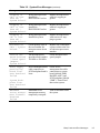
Table 3-2. System Error Messages
Message
Definition
Action
System battery is dead
- Replace
and run
Setup
System battery is
dead.
Replace battery and
run System Setup program.
System CMOS
checksum
bad - Run
Setup
Configuration data
is corrupted.
Run System Setup program to restore your
system configuration.
Incorrect
drive A type
- Run Setup
Incorrect
drive B type
- Run Setup
Diskette drive does
not match diskette
drive type stored in
configuration data.
Run System Setup program to restore your
system configuration.
Keyboard
error
Stuck key
Cable may be loose,
or keyboard may be
faulty.
Defective keyboard,
keyboard cable, or
system board.
System/
Shadow RAM
failed at
offset:
One or more
DIMMs may be
improperly seated or
faulty.
Reseat or replace
DIMMs.
Operating
system not
found
System did not find
bootable operating
system.
Use diskette with
bootable operating
system in drive A, or
load bootable
operating system
from hard-disk drive.
System
cache error
- Cache disabled
Microprocessor chip
malfunctioned.
Defective microprocessor or system
board.
System
timer error
Chip on system
board malfunctioned.
Defective microprocessor or system
board.
Beep Codes and Error Messages
3-3
Table 3-2. System Error Messages (continued)
Message
Definition
Action
Real-time
clock error
Real-time clock on
system board malfunctioned.
Defective microprocessor or system
board.
Keyboard
controller
error
Cable may be loose,
keyboard may be
faulty, or keyboard
controller is defective.
Defective keyboard,
keyboard cable, or
system board.
EISA configuration
NVRAM bad
EISA jumper may
have been accidentally installed.
Ensure EISA jumper
is removed; then
reboot system and
restore EISA configuration.
EISA configuration
error
EISA configuration
data in NVRAM
does not match the
installed EISA
expansion cards.
Ensure EISA expansion cards are seated
properly; then run
EISA Configuration
Utility.
Invalid CPU
speed
detected check
jumpers
Microprocessor
speed jumper plug
may be absent or
installed on wrong
jumper pins.
Check the microprocessor speed
jumpers.
Resource
conflict
Warning:
IRQ not
initialized
BIOS detected a
resource conflict
while configuring
Plug and Play ISA
or PCI expansion
card.
See “Eliminating
Resource Conflicts”
in Chapter 2.
System configuration
data write
error
System board may
be malfunctioning.
Defective system
board.
System memory size has
changed Run Configuration
Utility
DIMM was added or
removed. DIMMs
are improperly
seated.
More memory was
added. Make sure
DIMMs are properly
seated; run EISA
Configuration Utility.
Expansion
ROM not
initialized
3-4
Dell PowerEdge 4100/180 and 4100/200 Systems Service Manual
Table 3-2. System Error Messages (continued)
Message
Definition
Action
Stepping of
CPU1 is less
than sA1 System halted.
Wrong microprocessor
installed in
PROCESSOR1 socket.
Replace microprocessor
with sA1 stepping or
greater.
Stepping of
CPU2 is less
than sA1 System halted.
Wrong microprocessor
installed in
PROCESSOR2 socket.
Replace microprocessor
with sA1 stepping or
greater.
Stepping of
CPU is less
than sA1 System halted.
Wrong microprocessor
installed in system.
Replace microprocessor
with correct sA1 stepping or greater.
Nonidentical
CPUs - System
halted.
Cache memory sizes of
the two Pentium Pro
microprocessors do not
match.
Replace one of microprocessors so that cache size
of both microprocessors
matches.
Invalid CPU
speed detected
- Check speed
jumpers.
System halted.
The microprocessor
speed detected is neither
180 MHz or 200 MHz.
Check microprocessor
speed jumpers.
Power supply
paralleling
board firmware download
failed
Server-management bus
cable connection to
SCSI backplane board is
loose.
Check servermanagement bus cable
connections to system
board (labeled “SMB
BACKPLANE”) and
SCSI backplane (labeled
“SMB”). Turn off and
then restart system.
Embedded server
management memory
temporarily corrupted.
Turn off and then restart
the system.
System backplane firmware download
failed
Embedded
server management firmware
download
failed
Beep Codes and Error Messages
3-5
3-6
Dell PowerEdge 4100/180 and 4100/200 Systems Service Manual
Chapter 4
Removing and Replacing Parts
This chapter provides procedures for removing the components, assemblies,
and subassemblies in the system unit. Unless otherwise noted, each procedure
assumes the following:
• You have performed the steps in “Precautionary Measures” found later in
this chapter.
• You have removed the computer covers.
• You can replace or reinstall a part by performing the removal procedure in
reverse order unless additional information is provided.
Recommended Tools
Most of the procedures in this chapter require the use of one or more of the following tools:
•
•
•
•
•
•
•
Small flat-blade screwdriver
Wide flat-blade screwdriver
Number 1 and number 2 Phillips-head screwdrivers
Chip-removal tool
1/4-inch
nutdriver
Tweezers or long-nose pliers
Small plastic scribe
Also, use a wrist grounding strap as explained in the next section, “Precautionary Measures.”
Removing and Replacing Parts
4-1
Precautionary Measures
Before you perform any of the procedures in this chapter, take a few moments
to read the following warning for your personal safety and to prevent damage to
the computer system from ESD.
WARNING FOR YOUR PERSONAL SAFETY AND PROTECTION
OF THE EQUIPMENT: Only service technicians trained by Dell should
perform the following procedures. Before you start to work on the computer, perform the following steps in the sequence listed.
1. Turn off the computer and any attached peripherals.
2. Disconnect the computer and any attached peripherals from their
power sources to reduce the potential for personal injury.
3. Disconnect any communications cables.
4. Wear a wrist grounding strap, and clip it to an unpainted metal surface, such as a part of the back panel, on the computer chassis.
If a wrist grounding strap is not available, touch the fan guard or
some other unpainted metal surface on the back of the computer to
discharge any static charge from your body.
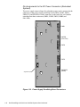
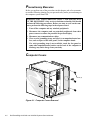
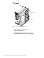
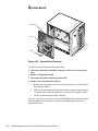
Computer Covers
screw (6)
Figure 4-1. Computer Covers Removal
4-2
Dell PowerEdge 4100/180 and 4100/200 Systems Service Manual
To remove a computer cover, follow these steps:
1. Turn the cover’s keylocks on the back panel of the computer to the
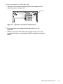
unlocked position (see Figure 4-2).
keylock (2)
Figure 4-2. Keylocks on Computer’s Back Panel
2. Loosen the three screws along the back edge of the cover (see
Figure 4-1).
3. Slide the cover toward the back of the computer an inch or so. Then
grasp the top of the cover at both ends, and lift it straight away from the
chassis.
Removing and Replacing Parts
4-3
Front Bezel
tab (4)
front bezel
Figure 4-3. Front Bezel Removal
To remove the front bezel, follow these steps:
1. Remove the computer covers.
2. Release the two tabs on each side of the bezel.
3. Slide the front bezel toward the front of the computer.
4-4
Dell PowerEdge 4100/180 and 4100/200 Systems Service Manual
Drives
Figure 4-4 shows an example of drive hardware that can be installed in the computer. Refer to this figure when you perform any of the procedures in the
following subsections.
3.5-inch diskette drive
DC power cable
SCSI2 CD-ROM
drive
diskette/tape drive
interface cable
SCSI hard-disk
drive bay (6)
SCSI backplane
board
diskette drive interface
connector (FLOPPY)
SCSI interface
cable
SCSI connector
(SCSI2 CD-ROM)
system board
SCSI connector
(BACKPLANE SCSI1)
Figure 4-4. Drive Hardware
Removing and Replacing Parts
4-5
Front-Panel Inserts
front-panel insert
tab (2)
latch (2)
back of the
front bezel
Figure 4-5. Front-Panel Insert Removal
To remove a front-panel insert, follow these steps:
1. Remove the front bezel.
2. From the back of the front bezel, press against the center of the insert
until the tabs come loose from the bezel.
3. Pull the insert out of the bezel.
To replace a front-panel insert, position the insert over the bay opening from the
inside of the front bezel and carefully press the insert into place. A tab on each
side of the insert snaps into a corresponding latch on the inside of the front
bezel.
4-6
Dell PowerEdge 4100/180 and 4100/200 Systems Service Manual
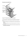
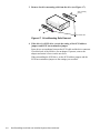
Externally Accessible Drives
3.5-inch diskette
drive in top bay
CD-ROM drive in
middle bay
lower-bay drive
position for optional
drive
drive-release
tab(2)
Figure 4-6. Externally Accessible Drives Removal
All of the externally accessible drives have drive-mounting rails. To remove a
drive assembly from one of the externally accessible drive bays, follow these
steps:
1. Disconnect the DC power cable and the interface cable from the back of
the drive.
Be sure to record the power connector number and interface cable connector
identification.
2. Press inward (toward center of drive) on the two drive-release tabs, and
slide the drive out of the bay.
Removing and Replacing Parts
4-7
3. Remove the drive-mounting rails from the drive (see Figure 4-7).
drive-mounting
rails (2)
drive-release tabs
Figure 4-7. Drive-Mounting Rails Removal
4. If the drive is a SCSI drive, record the setting of the SCSI address
jumpers and SCSI bus termination jumper.
Some drives use an adapter between the SCSI cable and the drive connector.
Check the back of the old drive for an adapter. If present, remove the
adapter and retain it for use on the new drive.
When reinstalling the SCSI drive, set the SCSI address jumpers and the
SCSI bus termination jumpers to the settings you recorded.
4-8
Dell PowerEdge 4100/180 and 4100/200 Systems Service Manual
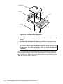
Hard-Disk Drives
drive bay
plastic drive handle
Figure 4-8. Hard-Disk Drive Carrier Removal
The hard-disk drives are mounted inside a hard-disk drive carrier. The hard-disk
drive carrier must be removed before a hard-disk drive can be removed. To
remove a hard-disk drive, follow these steps:
NOTES: Wait 20 seconds for the hard-disk drive to spin down before removing
the hard-disk drive carrier.
Hard-disk drives can be removed with the power on if a PowerEdge Expandable RAID Controller host adapter card is installed.
1. If a PowerEdge Expandable RAID Controller host adapter card is
installed in the computer, wait until the three indicators are off, and
then proceed to Step 2 (refer to Chapter 6, “Installing SCSI Hard-Disk
Drives,” in the User’s Guide for more information). If this host adapter
card is not installed in the computer, turn off the system before proceeding to Step 2.
2. Release the carrier by pulling down on the plastic drive handle.
3. Slide the drive carrier toward the front of the computer until it is free of
the drive bay.
4. Turn the drive carrier over, and place it on a flat work surface.
Removing and Replacing Parts
4-9
hard-disk drive
connector
carrier
screw (4)
Figure 4-9. Hard-Disk Drive Removal
5. Remove the four mounting screws that attach the hard-disk drive to the
carrier.
6. Disconnect the hard-disk drive from the connector on the back of the
carrier, and lift the drive from the carrier.
CAUTION: When disconnecting the hard-disk drive from the connector, grasp the connector, not the cable, to avoid damaging the
connector.
After you replace the drive and reinstall the carrier in the bay, turn on the system. The online indicator (green) lights, indicating power is being supplied to
the hard-disk drive. With the controller connected, the activity LED is activated
when the controller spins up the drive.
4-10
Dell PowerEdge 4100/180 and 4100/200 Systems Service Manual
SCSI Backplane Board
hard-disk drive
carrier
thumb screw
hook (10)
SCSI backplane board
Figure 4-10. SCSI Backplane Board Removal
To remove the SCSI backplane board, follow these steps:
1. Disconnect the hard-disk drive carrier connectors from the SCSI backplane board by sliding each carrier toward the front of the computer
approximately 1 inch.
2. Disconnect all cables from the SCSI backplane board.
3. Unscrew the thumb screw.
4. Disengage the board from the ten hooks holding the board to the computer chassis, and lift the board away from the computer.
An insulator (similar to the one for the power-supply paralleling board in
Figure 4-12) is attached to the back of the SCSI backplane board with two
adhesive strips.
Removing and Replacing Parts
4-11
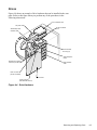
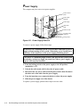
Power Supply
The computer may have one or two power supplies.
power closeout
panel
power supply
(optional)
power supply
cable strain
relief
insertion screw
AC power cable
connector
locking switch
Figure 4-11. Power Supply Removal
To remove a power supply, follow these steps:
WARNING: In a redundant system, you can remove and replace a power
supply without turning off the system. When doing so, be careful not to
touch any of the connectors on the power-supply paralleling board.
CAUTION: To maintain proper airflow and prevent the system from
overheating, each power supply bay must have either a power supply or
a power closeout panel installed.
1. Turn the locking switch on the power supply to the Off position
(marked by a “0”).
2. Unhook the cable strain relief to free the AC power cable.
3. Disconnect the AC power cable from the power outlet; then disconnect
the other end of the cable from the power supply.
4. Turn the insertion screw counterclockwise to release the power supply.
5. Slide the power supply out of the chassis.
To replace a power supply, perform these steps in reverse order.
4-12
Dell PowerEdge 4100/180 and 4100/200 Systems Service Manual
Power-Supply Paralleling Board
cables
thumb screw
power supply (2)
power-supply
paralleling board
insulator
hook slots (11)
power-supply
paralleling board
Figure 4-12. Power-Supply Paralleling Board Removal (Redundant
Systems)
To remove a power-supply paralleling board, follow these steps:
WARNING: Disconnect both power supplies from their AC power
source to prevent the possibility of getting shocked.
1. Disconnect the power supplies from the power-supply paralleling board
by sliding each power supply toward the back of the computer approximately 1 inch.
2. Disconnect all cables from the power-supply paralleling board.
3. Unscrew the thumb screw.
4. Disengage the board from the eleven hooks holding it to the computer
chassis, and then lift the board away from the computer.
Removing and Replacing Parts
4-13
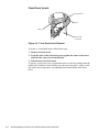
Power Connector Panel
power supply
retainer
screw
power
connector
panel
cables (5)
power
connector
panel
hook slots (4)
Figure 4-13. Power Connector Panel Removal (Nonredundant
Systems)
To remove the power connector panel, follow these steps:
1. Disconnect the power supply from the power connector panel by sliding
the power supply toward the back of the computer approximately
1 inch.
2. Disconnect all power connector panel cables (from the system board,
the SCSI backplane board, and so forth).
3. Unscrew the retainer screw.
4. Disengage the panel from the four hooks holding it to the computer
chassis, and then lift the panel away from the computer.
4-14
Dell PowerEdge 4100/180 and 4100/200 Systems Service Manual
Control Panel
screw
control panel
connector BP_to_CP
Figure 4-14. Control Panel Removal
To remove the control panel, follow these steps:
1. Remove the screw holding the control panel to the chassis.
2. Disconnect the cable from connector BP_to_CP.
3. Disengage the panel from the four hooks holding the panel to the
computer chassis, and lift the panel away from the computer.
Removing and Replacing Parts
4-15
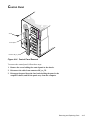
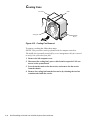
Cooling Fans
fan carrier
cooling fan
catch
retention
tab (2)
Figure 4-15. Cooling Fan Removal
To remove a cooling fan, follow these steps:
NOTES: This procedure can be performed with the computer turned on.
The middle fan is normally turned off by server management; this fan is turned
on only if one of the other fans fails.
1. Remove the left computer cover.
2. Disconnect the cooling fan’s power cable from its respective FAN connector on the system board.
3. Press down the catch on the fan carrier, and remove the fan carrier
from the chassis.
4. Remove the cooling fan from the fan carrier by releasing the two fan
retention tabs inside the carrier.
4-16
Dell PowerEdge 4100/180 and 4100/200 Systems Service Manual
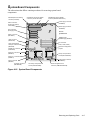
System Board Components
The subsections that follow contain procedures for removing system board
components.
diskette/tape drive interface
connector (FLOPPY)
Ultra/Narrow SCSI host adapter
connector (SCSI2 CD-ROM)
Ultra/Wide SCSI host adapter
connector (BACKPLANE SCSI1)
power supply connector
(POWER2)
EISA connectors
(EISA1 [top], EISA2,
and EISA3)
power supply connector
(POWER1)
PCI connectors
(PCI4 [top]–PCI8)
front of
system board
battery connector
(BATTERY)
DIMM sockets
(DIMM A [top]–DIMM H)
video connector
(MONITOR)
fan connectors
(FAN1, FAN2, FAN3)
server-management
serial port connector
(REMOTE)
speed and configuration
jumpers
parallel port connector
(PARALLEL)
serial port 2 connector
(SERIAL2)
primary microprocessor
socket (PROCESSOR1)
serial port 1 connector
(SERIAL1)
mouse connector
(MOUSE)
keyboard connector
(KEYBOARD)
power supply connector
(POWER3)
secondary microprocessor
socket (PROCESSOR2)
server-management bus
connector (SMB BACKPLANE)
Figure 4-16. System Board Components
Removing and Replacing Parts
4-17
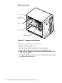
Expansion Cards
card-slot opening
card-mounting
bracket
retaining screw
expansion card
locking card guide
Figure 4-17. Expansion Card Removal
To remove an expansion card, follow these steps:
1. Remove the left computer cover.
2. Disconnect any cables connected to the expansion card.
3. Remove the retaining screw from the card-mounting bracket.
4. If the card is a full-length expansion card, unlock the locking cam on
the locking card guide.
5. Grasp the expansion card by its corners, and carefully remove it from
the expansion-card connector.
4-18
Dell PowerEdge 4100/180 and 4100/200 Systems Service Manual
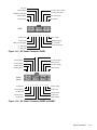
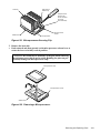
DIMMs
DIMM
securing clip (2)
2.
1.
Figure 4-18. DIMM Removal
To remove a DIMM, push outward on the DIMM socket’s securing clips until the
DIMM is released from its socket. Then lift the DIMM away from the socket.
DIMM
securing clip (2)
2.
1.
Figure 4-19. DIMM Installation
To replace a DIMM, push outward on the securing clips at each end of the
socket until they snap open. Orient the DIMM to the socket, and press the
DIMM straight down into the socket slot until the securing clips snap into place
around both ends of the DIMM.
Removing and Replacing Parts
4-19
Microprocessor and Heat Sink
clip
heat sink
thermal pad
(bonded to heat sink)
microprocessor
socket
microprocessor
pin-1 corner of socket
front tab
Figure 4-20. Microprocessor Configuration
The computer may have two microprocessors. To remove a microprocessor and
heat sink, follow these steps:
1. Remove the microprocessor securing clip from the microprocessor/heat
sink assembly.
WARNING: The microprocessor chip can get extremely hot during
system operations. Be sure the chip has had sufficient time to cool
before touching it.
Press down on the folded part of the clip with a small screwdriver to release
the clip (see Figure 4-21).
4-20
Dell PowerEdge 4100/180 and 4100/200 Systems Service Manual
press here to
release clip
heat sink
microprocessor
securing clip
hooks over tabs
on socket
(front and back)
release lever
microprocessor
socket
microprocessor
Figure 4-21. Microprocessor Securing Clip
2. Remove the heat sink.
3. Push outward and then upward on the microprocessor release lever to
rotate the lever to its fully vertical position.
CAUTION: Be careful not to bend any of the pins when removing
the microprocessor chip from its socket. Bending the pins can permanently damage the microprocessor chip.
microprocessor chip
microprocessor socket
release lever
Figure 4-22. Removing a Microprocessor
Removing and Replacing Parts
4-21
4. Lift the microprocessor out of its socket.
To install the replacement microprocessor/heat sink assembly, ensure that the microprocessor release lever is in its fully vertical position to allow the microprocessor pins
to easily slip into the socket. When the microprocessor/heat sink assembly is in place,
rotate the microprocessor release lever to its horizontal position. Hook the microprocessor securing clip over the socket tab nearest the front of the system board, and
then snap it over the tab on the back of the socket.
pin-1 corner
(gold finger and bevel)
Figure 4-23. Pin-1 Identification
NOTE: Pin 1 on the microprocessor is located on the corner with the largest
bevel. The pin-1 hole in the microprocessor socket is located on the corner
where the holes are in a diagonal pattern.
If you are installing a new microprocessor and heat sink, place the thermal
interface pad that comes with the replacement microprocessor between the
microprocessor and the heat sink before reinstalling the securing clip.
4-22
Dell PowerEdge 4100/180 and 4100/200 Systems Service Manual
System Battery
battery
BATTERY socket
Figure 4-24. System Battery Removal
To remove the system battery, follow these steps:
1. If possible, enter the System Setup program, and make a printed copy
of the system setup screens.
2. Remove the left computer cover.
See “Computers Covers” found earlier in this chapter.
3. Remove the battery.
Pry the battery out of its socket with your fingers or with a blunt, nonconducting object, such as a plastic screwdriver.
To replace the system battery, follow these steps.
WARNING: The new battery can explode if installed incorrectly. Be
careful to replace the battery as instructed in the following procedure. In
addition, replace the old battery only with one of the same or an equivalent type, as recommended by the manufacturer. Discard the old battery
according to the manufacturer’s instructions.
1. Orient the new battery with the “+” facing up. Insert the battery into its
socket, and snap it into place.
2. Start the System Setup program, and reset the Time and Date categories.
Also, compare the system configuration information with the copy of the
system configuration settings you made in step 1 of the removal procedure. Restore
any system configuration information that was lost while replacing the battery.
Removing and Replacing Parts
4-23
System Board
system board
slot (13)
screw
Figure 4-25. System Board Removal
To remove the system board, follow these steps:
1. Disconnect all cables from their connectors at the back of the system
unit.
2. Remove all expansion cards.
3. Disconnect all cables from the system board.
4. Remove the system board as follows:
a. Remove the screw that secures the system board to the vertical wall of
the computer chassis.
b. Slide the system board toward the front of the computer approximately
1/2 inch to release the board from the 13 slots in the computer chassis.
c. Lift the system board out of the computer.
If you are replacing a system board, remove the DIMMs, the microprocessor(s),
and the expansion card from the old system board and install them on the
replacement board.
4-24
Dell PowerEdge 4100/180 and 4100/200 Systems Service Manual
Appendix A
System Setup Program
This appendix describes the System Setup program, which is used to set or
change the system configuration information stored in NVRAM on the system
board.
To enter the System Setup program, press <F2> during the power-on self-test
(POST).
If you wait too long, the operating system begins to load into memory and you
cannot enter the System Setup program. Let the system complete the load operation;
then shut down the system and try again.
NOTE: To ensure an orderly system shutdown, consult the documentation that
accompanied the operating system.
System Setup Screens
The System Setup program is a menu-driven program. Use the left- and rightarrow keys to move between the following four menus:
• Main menu — Provides settings for the basic system configuration
• Advanced menu — Provides detailed settings for some system features
• Security menu — Provides settings for password status, diskette access,
virus check reminder, and system backup reminder
• Exit menu — Provides settings for saving and loading the configurations
and options
In addition to the initial menu selections, some selections have submenus.
These selections are identified by an arrow to the left of the selection.
Screen Conventions
Information on the System Setup screens is organized in four boxed areas (see
Figure A-1):
• Title box — Contains information about the system and menu selections
• Configuration options and system data box — Lists configuration categories
(left column) and settings or information (right column)
• Help box — Displays item-specific help for the category whose field is currently highlighted
• Key functions box — Lists the System Setup keys and their functions
System Setup Program
A-1
Key Functions
Table A-1 lists the System Setup keys and their functions.
Table A-1. Key Functions
A-2
Key Combination
Function
<F1> or <Alt><h>
Displays the general help window
<Esc>
Displays the Exit menu, or the parent
menu if you are in a submenu
Left-arrow key or
right-arrow key
Selects a different menu
Up-arrow key or
down-arrow key
Moves the cursor up or down
<Tab>
Moves the cursor to the next field
<Shift><Tab>
Moves the cursor to the previous field
<Home> or <End>
Moves the cursor to the top or bottom of
the window
<F5> or <->
Selects a lower value for the field
<F6> or <+> or
<Spacebar>
Selects a higher value for the field
<F9>
Sets the default configuration values for
the current menu
<Alt><d>
Loads the default System Setup values for
all menus
<F10>
Loads previously stored configuration
values for the current menu
<Enter>
Executes a command or selects a
submenu
<Alt><r>
Refreshes the screen
Dell PowerEdge 4100/180 and 4100/200 Systems Service Manual
Screen Color Combinations
In addition to its text, a field’s color identifies the type of information it contains, as follows:
• Black on cyan — Headers and footers, including the title box at the top of
the screen and the key functions box at the bottom of the screen.
• Blue on white — Configuration information that cannot be changed by the
user, such as category titles.
• Black on white — Fields that can be changed by the user, but are not
selected. Also used for help messages.
• Bright white on white — The highlight color for a category title that is
selected. Also used to highlight the function keys in the key functions box.
• White on black — The highlight color for an input field that is selected.
Main Menu
configuration options and system data box
help box
title box
BIOS Version AXX
Dell System PowerEdge 4100/200 Setup
Main Advanced Security Exit
F1
ESC
Time:
[5:01:96]
Date:
[May 04, 1996]
Diskette Drive A:
[1.44 MB, 3.5 inch]
Diskette Drive B:
[Not Installed]
Fast Video BIOS:
[On and Cached]
Memory Cache:
[Enable]
Boot Sequence:
[A: then C:]
Num Lock:
[On]
Speaker:
[On]
Processor 1:
Processor 2:
Level 2 Cache:
Pentium Pro 200
Pentium Pro 200
512 KB
Base Memory:
640 KB
Extended Memory:
63 MB
Video Memory:
1 MB
Service Tag:
AB12Z
Item Specific Help
Asset Tag:
123456789A
Help
Select Item
-/+
Change Values
Exit
Select Menu
Enter
Select Sub-Menu
Resets the time on the
computer’s internal
clock. Time kept in a
24-hour format. Press
<Tab>, <Shift-Tab>,
or <Enter> selects
fields
F9
Setup Defaults
F10
Previous Values
key functions box
Figure A-1. Main Menu
System Setup Program
A-3
Table A-2. Main Menu Categories
A-4
Category
Function
Time
Resets time on system’s internal clock.
Date
Resets date on system’s internal calendar.
Diskette Drive A or
Diskette Drive B
Identifies type of diskette drives installed.
Category options always match physical
locations of drives in system. Tape drives are
not reflected in these categories.
Fast Video BIOS
Enables shadowing and caching the BIOS
for the video controller.
Memory Cache
Enables or disables the cache memory in
the microprocessor.
Boot Sequence
Displays a submenu. See the next subsection, “Boot Options Submenu.”
Num Lock
Determines whether keyboard’s Num Lock
mode is activated at boot.
Speaker
Enables or disables the system speaker.
Processor 1
Displays type of microprocessor installed
in PROCESSOR1 socket.
Processor 2
Displays type of microprocessor installed
in PROCESSOR2 socket.
Level 2 Cache
Displays amount of level-2 cache memory
in the microprocessor.
Base Memory
Displays amount of memory available to
MS-DOS programs that do not use
extended or expanded memory.
Extended Memory
Displays amount of memory available as
extended memory.
Video Memory
Displays amount of video memory
installed on the system board.
Service Tag
Displays system’s five-character service
tag number.
Asset Tag
Displays the asset tag number, up to ten
characters, if one is assigned.
Dell PowerEdge 4100/180 and 4100/200 Systems Service Manual
Boot Options Submenu
BIOS Version AXX
Dell System PowerEdge 4100/200 Setup
Main Advanced Security Exit
Boot Options
Item Specific Help
Boot Sequence:
[A: then C:]
Setup Prompt:
[Enabled]
POST Errors:
[Enabled]
Determines the order
of drives from which
the system tries to
boot.
Diskette Drive Check: [Enabled]
Reset Button:
[Enabled]
F1
Help
Select Item
-/+
Change Values
F9
Setup Defaults
ESC
Exit
Select Menu
Enter
Select Sub-Menu
F10
Previous Values
Figure A-2. Boot Options Submenu
Table A-3. Boot Options Submenu Categories
Category
Function
Boot Sequence
Determines the sequence in which the
drives are searched to find the boot program after power-on
Setup Prompt
Enables or disables the “
” message during boot
Post Errors
Enables or disables the “
”
message during boot
Diskette Drive Check
Enables or disables checking for type of
diskette drive during boot
Reset Button
Enables or disables the reset button on the
front bezel
System Setup Program
A-5
Advanced Menu
Dell System PowerEdge 4100/200 Setup
Main Advanced Security Exit
BIOS Version AXX
Item Specific Help
Serial Port 1:
[3F8, IRQ 4]
Serial Port 2:
[2F8, IRQ 3]
Parallel Port:
[378, IRQ 7]
Parallel Mode:
[Output only]
Diskette Controller:
[Enabled]
On-Board SCSI A:
[Enabled]
On-Board SCSI B:
{Enabled}
PCI Scan Sequence
[Embedded devices first]
Use MP Specification
{1.4}
PS/2 Mouse
[Enabled]
Configures the system’s
built-in serial port.
F1
Help
Select Item
-/+
Change Values
F9
ESC
Exit
Select Menu
Enter
Select Sub-Menu
F10 Previous Values
Figure A-3. Advanced Menu
A-6
Dell PowerEdge 4100/180 and 4100/200 Systems Service Manual
Setup Defaults
Table A-4. Advanced Menu Categories
Category
Function
Serial Port 1 or
Serial Port 2
Configures system’s built-in serial ports.
Parallel Port
Configures system’s built-in parallel port.
The port’s I/O address may be set to:
278H, IRQ5; 3BCH, IRQ7; 378H, IRQ7.
Otherwise, the port may be disabled.
Parallel Mode
Controls whether system’s built-in parallel
port acts as an AT-compatible (Output
Only), PS/2-compatible (Bidirectional), or
ECP (extended capabilities port).
Diskette Controller
Enables system’s built-in diskette
controller.
On-Board SCSI A
Enables or disables the built-in SCSI 7880
Ultra/Wide controller and determines if it is
scanned as a boot drive.
On-Board SCSI B
Enables or disables the built-in SCSI 7860
Ultra/Narrow controller and determines if
it is scanned as a boot drive.
PCI Scan Sequence
Determines the sequence the PCI devices
are scanned to find a boot device (default is
Embedded devices first).
Use MP Specification
Determines the microprocessorspecification revision level: either 1.1 or
1.4 (default).
PS/2 Mouse
Enables or disables the built-in mouse controller.
System Setup Program
A-7
Security Menu
BIOS Version AXX
Dell System PowerEdge 4100/200 Setup
Main Advanced Security Exit
Item Specific Help
Supervisor Password Is Disabled
User Password Is
<ENTER>
Disabled
Set Supervisor Password[Press Enter]
Set User Password
[Press Enter]
Password on Boot
[Disabled]
Diskette Access
[User]
System Backup Reminder [Disabled]
Virus Check Reminder
[Disabled]
F1
Help
Select Item
-/+
Change Values
F9
ESC
Exit
Select Menu
Enter
Select Sub-Menu
F10 Previous Values
Figure A-4. Security Menu
A-8
Dell PowerEdge 4100/180 and 4100/200 Systems Service Manual
Setup Defaults
Table A-5. Security Menu Categories
Category
Function
Supervisor Password Is
Displays current status of the supervisor
password (enabled or disabled). See “Using
the Supervisor Password Feature” in Chapter 4 of the User’s Guide.
User Password Is
Displays current status of user password
(enabled or disabled). See “Using the User
Password Feature” in Chapter 4 of the
User’s Guide.
Set Supervisor Password
Displays a dialog box for entering a new
user password (up to seven alphanumeric
characters). See “Using the Supervisor
Password Feature” in Chapter 4 of the
User’s Guide.
Set User Password
Displays a dialog box for entering a new
user password (up to seven alphanumeric
characters). See “Using the User Password
Feature” in Chapter 4 of the User’s Guide.
Password on Boot
Allows you to require the entry of a supervisor password before the boot process of
the system can be completed. Requires use
of a supervisor password.
Diskette Access
Restricts access to the diskette drive.
Requires use of a supervisor password.
System Backup
Reminder
Enables or disables a system-backup
reminder message at boot.
Virus Check Reminder
Enables or disables a virus-check reminder
message at boot.
System Setup Program
A-9
Exit Menu
BIOS Version AXX
Dell System PowerEdge 4100/200 Setup
Main Advanced Security Exit
Item Specific Help
Save Changes & Exit
Saves all changes made
in the Setup program to
CMOS, exits the Setup
program, and then reboots the computer.
Exit Without Saving Changes
Get Default Values
Load Previous Values
Save Changes
F1
Help
Select Item
-/+
Change Values
F9
ESC
Exit
Select Menu
Enter
Select Sub-Menu
F10 Previous Values
Figure A-5. Exit Menu
A-10
Dell PowerEdge 4100/180 and 4100/200 Systems Service Manual
Setup Defaults
Table A-6. Exit Menu Categories
Category
Function
Save Changes and Exit
Saves the changes you have made before
you exit the System Setup program. The
next time you boot up, the BIOS configures
your system according to the selections
stored in CMOS.
Exit Without Saving
Changes
Exits the System Setup program without
saving any of the changes you have made.
Get Default Values
Loads the default values for each menu in
the System Setup program.
Load Previous Values
Loads the values previously stored in
CMOS for each menu.
Save Changes
Stores your changes in CMOS, but does not
exit the System Setup program.
System Setup Program
A-11
A-12
Dell PowerEdge 4100/180 and 4100/200 Systems Service Manual
Index
A
configuration guidelines
SCSI drives, 1-9
AC power receptacle
about, 1-7
location on I/O panel, 1-7
configuration jumpers
location on system board, 4-17
B
battery
connector, 4-17
illustrated, 4-23
removing and replacing, 4-23
connectors
location on system board, 4-17
control panel
connector, 4-17
illustrated, 1-5
removal, 4-15
cover, system unit
removal, 4-2
BATTERY connector, 4-17
beep codes, 3-1
boot routine
observing when troubleshooting, 2-3
C
cables
DC power, 1-12
card-slot opening, 4-18
carrier, hard-disk drive
removal, 4-9
CD-ROM drive
illustrated, 4-5
removal, 4-7
computer
back/right side internal view, 1-6
front/left internal view, 1-5
orientation, 1-3
technical specifications, 1-24
D
DC power
about, 1-11
connectors, 1-12, 1-16
pin assignments, 1-12, 1-16
DC power distribution
nonredundant system, 1-15
redundant system, 1-19
diagnostics, 2-6
DIMMs
about, 1-21
ECC, 1-8
location on system board, 4-17
removal, 4-19
socket population rules, 1-8
diskette drive
illustrated, 4-5
removal, 4-7
diskette/tape drive interface connector, 4-17
diskette-based diagnostics, 2-5
Index
1
DREQ line assignments, 1-23
drive bays
external, 1-5, 1-6
internal, 1-5, 1-6
drives
about, 1-25
illustrated, 4-5
SCSI configuration guidelines, 1-9
SCSI ID numbers, 1-10
SCSI termination jumpers, 1-10
H
hard-disk drives
connectors, 4-17
drive bays, 1-5, 1-6
hard-disk drives, SCSI
carrier removal, 4-9
configurations, 1-9
illustrated, 4-5
help, getting, 2-6
E
I
ECC, 1-8
EISA expansion cards, 1-8
indicator card
removal, 4-11
EISA expansion-card connectors, 4-17
initial procedures, 2-1
error messages, system
list of, 3-3
initialization error messages, 3-3
expansion cards
card-slot opening, 4-18
connectors, 4-17
removal, 4-18
slots, 1-8
expansion subsystem, 1-8
integrated features
SCSI controllers, 1-9
server management, 1-8
video controller, 1-9
interrupt assignments
list of, 1-22
ISA expansion cards, 4-18
external visual inspection, 2-2
externally accessible drives
removal, 4-7
F
J
jumpers
list of, 1-22
FAN connectors, 4-17
fan connectors, 4-17
K
fatal error messages, 3-3
KEYBOARD connector, 4-17
FLOPPY connector, 4-17
keyboard connector
location on I/O panel, 1-7
location on system board, 4-17
front bezel
removal, 4-4
front-panel inserts
removal, 4-6
2
Dell PowerEdge 4100/180 and 4100/200 Systems Service Manual
M
memory
main, 1-21
system, 1-8
messages, error, 3-3
microprocessor
release lever, 4-21
removal, 4-20, 4-21
sockets, 4-17
power supply
about, 1-11
connector configuration, 1-12
connectors, 4-17
DC voltage ranges, 1-11
illustrated, 1-12
removal, 4-12
voltage output ranges, 1-11
POWER1 connector, 4-17
POWER2 connector, 4-17
MONITOR connector, 4-17
power-supply paralleling board
connector configuration, 1-16
illustrated, 1-16
removal, 4-13
MOUSE connector, 4-17
precautions, 4-2
mouse connector
location on I/O panel, 1-7
location on system board, 4-17
PROCESSOR1 connector, 4-17
P
R
padlock, 4-3
REMOTE connector, 4-17
PARALLEL connector, 4-17
reset button
location on I/O panel, 1-4
parallel port connector
location on I/O panel, 1-7
location on the system board, 4-17
resource conflicts
eliminating, 2-5
microprocessor cooling fans
removal, 4-16
PROCESSOR2 connector, 4-17
PCI expansion cards, 1-8, 4-18
PCI expansion-card connectors, 4-17
Plug and Play ISA expansion cards, 1-8
S
POST beep codes, 3-1
SCSI BACKPLANE connector, 4-17
power
AC power receptacle, 1-7
indicator, 1-4
switch, 1-4
SCSI CD-ROM connector, 4-17
power connector plate
removal, 4-14
SCSI devices
ID numbers, 1-10
power distribution diagram
nonredundant system, 1-15
redundant system, 1-19
SCSI hard-disk drives. See hard-disk drives,
SCSI
SCSI connectors, 4-17
SCSI controllers, integrated, 1-9
SCSI ID numbers, 1-10
SERIAL connectors, 4-17
Index
3
serial port connectors
location on I/O panel, 1-7
location on system board, 4-17
system specifications, 1-24
system unit cover, 4-2
server-management bus connector, 4-17
server-management serial port connector
location on I/O panel, 1-7
location on system board, 4-17
SMB BACKPLANE connector, 4-17
sockets
battery, 4-23
DIMM, 4-17, 4-19
specifications, technical, 1-24
subsystems
advanced expansion, 1-8
main memory, 1-21
T
technical specifications, 1-24
termination jumpers
SCSI drives, 1-10
troubleshooting
boot routine, interpreting, 2-3
external visual inspection, 2-2
initial procedures, 2-1
initial user contact, 2-1
internal visual inspection, 2-4
system board
components, 4-17
illustrated, 1-20
jumpers, 1-21
location, 1-5
removing and replacing, 4-24
U
system board jumpers, 1-21
Ultra/Wide SCSI host adapter connector, 4-
system error messages
list of, 3-3
Ultra/Narrow SCSI host adapter connector,
4-17
17
user contact, initial, 2-1
system features, 1-1
system power supply, 1-11
System Setup program
advanced menu, A-6
boot options submenu, A-5
exit menu, A-10
key functions, A-2
main menu, A-3
menus, A-1
screen color combinations, A-3
screen conventions, A-1
security menu, A-8
starting, A-1
4
V
video connector
location on I/O panel, 1-7
location on system board, 4-17
video controller, integrated, 1-9
visual inspection
external, 2-2
internal, 2-4
Dell PowerEdge 4100/180 and 4100/200 Systems Service Manual