1
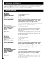
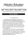
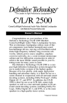
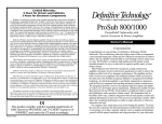
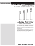
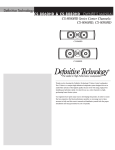
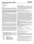
BP7000SC/BP7001SC
Bipolar Loudspeaker with Built-In Powered SuperCube® Technology Subwoofers
Owner’s Manual
Congratulations
Congratulations on your purchase of the Definitive
Technology BP7000SC/BP7001SC Bipolar Loudspeaker
System. The BP7000SC/BP7001SC are very unique
speakers which combine our award-winning patented bipolar
technology with a built-in side-firing SuperCube Technology
subwoofer system complete with ultra-high power digital
amplifiers. These extraordinary speakers truly revolutionize
the state-of-the-art in music and home theater loudspeakers.
Our engineers have spent many years in developing this
product. In order to ensure that you experience the finest
performance possible, we encourage you to take a moment
to fully read this owner’s manual and familiarize yourself
with the proper installation and set-up procedures for your
BP7000SC/BP7001SC speakers.
Safety Precautions
CAUTION
RISK OF ELECTRIC SHOCK
DO NOT OPEN
CAUTION! To reduce the risk of electric shock and fire, do not remove the cover or back plate of
this device. There are no user serviceable parts inside. Please refer all servicing to licensed service
technicians. Avis: Risque de choc electricque, ne pas ouvrir.
CAUTION! The international symbol of a lightning bolt inside a triangle is intended to alert the
user to uninsulated “dangerous voltage” within the device’s enclosure. The international symbol
of an exclamation point inside a triangle is intended to alert the user to the presence of important
operating, maintenance and servicing information in the manual accompanying the device.
CAUTION! To prevent electrical shock, match wide blade of plug to wide slot, fully insert.
Attention: Pour eviter les chocs electriques, introduire la lame la plus large de la fiche dans la
borne correspondante de la prise et pousser jusqu'au fond.
CAUTION! To reduce the risk of electrical shock, do not expose this equipment to rain
or moisture.
1.
2.
3.
4.
5.
6.
7.
Read Instructions—All safety and operating instructions should be read before operating the device.
Retain Instructions—The safety and operating instructions should be retained for future reference.
Heed Warnings—All warnings on the device and in the operating instructions should be adhered to.
Follow Instructions—All operating and safety instructions should be followed.
Water & Moisture—The device should never be used in, on or near water for risk of fatal shock.
Carts & Stands—The device should only be used on carts or stands recommended by the manufacturer.
Wall & Ceiling Mounting—The device should be mounted on a wall or ceiling only as recommended by the
manufacturer.
8. Ventilation—The device should always be located in such a way that it maintains proper ventilation. It should
never be placed in a built-in installation or anywhere that may impede the flow of air through its heat sink.
9. Heat—Never locate the device near heat sources such as radiators, floor registers, stoves or other heatgenerating devices.
10. Power Supply—The device should only be connected to a power supply of the type described in the operating
instructions or as marked on the device.
11. Power Cord Protection—Power cables should be routed so they are not likely to be stepped on or crushed by
items placed on them or against them. Special attention should be paid to areas where the plug enters a socket or
fused strip and where the cord exits the device.
12. Cleaning—The device should be cleaned in accordance with manufacturer’s instructions.
13. Periods Of Non-Use—The device should be unplugged when not being used for extended periods.
14. Dangerous Entry—Care should be taken that no foreign objects or liquids fall or are spilled inside the device.
15. Damage Requiring Service—The device should be serviced by licensed technicians when:
• The plug or power supply cord has been damaged.
• Objects have fallen or liquid has spilled inside the device.
• The device has been exposed to moisture.
• The device does not appear to be operating properly or exhibits a marked change in performance.
• The device has been dropped or the cabinet becomes damaged.
16. Service—The device should always be serviced by licensed technicians. Only replacement parts specified
by the manufacturer should be used. The use of unauthorized substitutions may result in fire, shock, or
other hazards.
CAUTION
Important Safety Instructions
To reduce the risk of the product inadvertently tipping over, four stabilizer brackets with mounting screws
have been supplied. These must be installed in the base of the product in the slots provided.
Installation Instructions:
Tools required: Philips screw driver (not supplied)
Parts required: Four stabilizer brackets (supplied), eight screws (supplied)
Instructions:
1. Carefully lay the speaker on its front surface.
2. Place one of the stabilizer brackets in the rear slot provided. (Note: Stabilizer bracket will be flush with bottom
of base.)
2
3. Insert two screws provided and tighten them securely, being careful not to strip out material.
4. Repeat steps #2 and #3 for the other stabilizer brackets.
5. Remove the supporting feet closest to the stabilizer brackets and thread them into the brass insert in
the stabilizer brackets.
6. Carefully return the speaker to the upright position and adjust the glides (supporting feet) to level the speaker.
Note: If desired, the four glides (support feet) may be replaced and the four spikes provided may be installed.
The four spikes or glides must be fully threaded into the brass inserts on the stabilizer brackets.
AVERTISSEMENT
Mesures de Sécurité Importantes
Pour réduire les risques que le produit se renverse par inadvertance, quatre supports stabiliseurs avec vis de montage
ont été fournis. Ceux-ci doivent être installés sur la base du produit, dans les rainures appropriées.
Procédures d’installation:
Outils requis: Tournevis étoile (non fourni)
Pièces requises: Quatre supports stabiliseurs (fournis), huit vis (fournies)
Instructions:
1. Coucher soigneusement le haut-parleur sur la face avant.
2. Placer un des supports stabiliseurs dans la rainure appropriée arrière. (Note: le support stabiliseur sera égal
au bas de la base)
3. Insérer deux des vis prévues à cet effet et serrer de façon ajustée en prenant garde de ne pas élimer les parois
du matériel.
4. Répéter les étapes #2 et #3 pour l’autre support stabiliseur.
5. Retirer les niveleurs (pieds de support) les plus rapprochés des supports stabiliseurs et visser les niveleurs, dans
l’encolure de cuivre des supports stabiliseurs.
6. Relever soigneusement le haut-parleur dans sa position fonctionnelle et ajuster les niveleurs (pieds de support) pour
égaliser le haut-parleur.
Note: Les quatres niveleurs (pieds de support) peuvent être remplacés, si désiré, par les quatres pointes fournies
à cet effet.
Unpacking Your BP7000SC/BP7001SCs
Please Inspect For Shipping Damage
Each loudspeaker leaves our plant in perfect condition. Any visible or
concealed damage most likely occurred in handling after it left our plant and
should be reported at once to your Definitive dealer or the delivery company that
delivered your loudspeaker. Please unpack your system carefully. Save all cartons
and packing materials in case you move or need to ship your system. Record the
serial number found on the back of the BP7000SC/BP7001SC in the appropriate
place on your warranty card, answer all questions and send it in.
Positioning the Speakers in Your Room
It is important, because of the BP7000sc/BP7001sc’s unique bipolar
(front and rear) radiation pattern, that some simple set-up recommendations be
followed in order to assure optimum performance in your room. Please remember
that although these recommendations are usually valid, all rooms and listening
set-ups are somewhat unique, so do not be afraid to experiment with the speakers.
Remember, whatever sounds best to you is correct.
In most rooms the speakers should be placed 5 to 36 inches from the rear wall
in order to allow the rear radiated sound to freely reflect off the back wall. Please
note that they can go closer to, or further from, the wall if desired. Placement
closer to the rear wall will increase the bass output while placement further from
the rear wall will decrease the bass output (which, of course, can be compensated
3
for with the speakers’ low frequency controls). Sometimes placement further
from the rear wall will increase spaciousness and the sense of depth.
The speakers should usually be placed a minimum of 5 to 7 feet apart and kept
away from the side walls and corners if possible. A good rule of thumb is to place
the speakers separated by one half the length of the wall they are positioned along,
and each speaker one quarter the length of the back wall away from the side wall.
Speakers may be angled in toward the listening position or left parallel with
each other. Angling the speakers in (pointed directly at the listener) will result in a
somewhat brighter, clearer sound with a sharper focus and a more solid central
image (generally, we recommend this), while leaving the speakers parallel with
each other will result in a less bright, more diffuse sound. Try to leave the space on
the sides of the speakers as open and unobstructed as possible so that there will be
no interference with the rear radiated sound.
The BP7000SC/BP7001SCs are mirror imaged (packing cartons are labeled
speaker 1 and speaker 2) with a flat-coned radiator on the bottom of each side and
one active driver around waist-high (which you can feel through the grille cloth).
The side-mounted subwoofers are located so they may be set up with both waist
high active woofers facing in (toward each other) or both active woofers facing
out (away from each other). (Feel the side of the speakers about waist high to
determine which side the woofer is on.) Facing the active woofers in or out will
vary the sound somewhat and which way is best will vary with your room.
Usually, we start with the active woofers facing in as this is often the way it
sounds best. Again, experiment to determine the best location for the speakers.
Often, adjusting the spikes or feet of the BP7001SC so that the front of the speaker
is approximately 1/2" to 3/4" higher than the rear will provide better sound.
“Spiking” Your Loudspeakers
An optional “spiking” kit has been provided should you desire to “spike”
your loudspeakers. “Spiking” your loudspeakers will provide greater stability
when placing your loudspeakers on carpeting and will also, according
to many experts, result in an overall improvement in sonic performance.
Care should be taken when using spikes as they may cause damage to wooden
or other floors which are susceptible to being scratched. Definitive Technology
is specifically not responsible for damage which may result from the use
of spikes.
The spike kit contains four spikes. To install, unscrew the plastic guides on
the stabilizer brackets. Then screw the four spikes into the brass inserts on the
stabilizer brackets. Then, with the help of another person, lift the speaker upright
and lower it to its exact desired position on the floor. You must lower the speaker
to the exact position you want because once the spikes are in place you cannot
move the speakers sideways on the rug or floor – this may damage the floor or
the speakers. Next, adjust the spikes so the speaker sits solidly on all four spikes
(and does not rock).
4
Speaker Break-In
Your BP7000SC/BP7001SCs should sound good right out of the box; however,
an extended break-in period of 40-60 hours or more of normal playing is required
to reach full performance capability. Break-in allows the suspensions to work in
and results in fuller bass, a more open “blossoming” midrange and smoother high
frequency reproduction.
Connecting Your Loudspeakers
Connecting Your Speakers to Your Electronics
Your BP7000SC/BP7001SCs may be connected in several different ways.
There are two sets of speaker level (high level) 5-way binding posts. In addition,
each speaker has an LFE input. This input can be used with Dolby Digital* and
DTS* 5.1 (6.1, 7.1) decoders to separately feed the discrete “Low Frequency
Effects” channel into each subwoofer (which then combines with the low bass
present separately in the left or right channel signals). If desired, you may hook
up your BP7000SC/BP7001SCs simply by running one set of speaker wires from
your amplifier to each BP7000SC/BP7001SCs, or as complexly as bi-wiring
the low/mid- and high-frequency section of each BP7000SC/ BP7001SCs in
conjunction with running a separate low-level input to the LFE input of the
subwoofer section of each speaker. Your BP7000SC/BP7001SCs will deliver
exceptional performance no matter which hook-up method you use. The more
complex methods are often chosen by advanced hobbyists to extract the last 1%
of performance potential from the speakers, while most listeners use the simplest
hook-ups which also deliver superb performance. Unlike a conventional system,
where the subwoofer is driven only by an LFE subwoofer signal, the BP7000SC/
BP7001SCs are much more sophisticated and are driven by the left or right channel
signal as well as the LFE signal. For optimum performance, please read through
these instructions fully and follow them.
* Registered Trademarks.
5
Rear Panel
* This section of the
rear panel will be
shown on the
connection
diagrams.
Gold Jumper
6
Connecting Each Speaker with One Pair of Speaker
Wires Only
With all the gold jumpers in place (see Diagram # 1), simply connect any of
the red (+) terminals of each speaker to the red (+) terminal of its channel on
your amplifier or receiver, and any of the black (-) terminals of each speaker to
the black (-) terminal of its channel on your amplifier or receiver. It is essential
that both speakers be connected in the same way (in phase) to its own channel
of the amplifier. If you experience a great lack of bass, it is likely that one speaker
is out of phase with the other.
If you have a Dolby Digital system, “tell” your bass management system
that you have “Large” left and right front speakers and “No” subwoofer.
The base management system will then send the LFE .1 channel signal into
the left and right channels, and it will be reproduced by the subwoofers in your
BP7000SC/ BP7001SCs, giving you all the benefits of Dolby Digital and the
discrete LFE signal.
When the speakers are hooked up using simply one set of speaker wire per
speaker (with no separate low level input for the subwoofer section), a special
circuit takes an infinitesimally small signal from the speaker level input and
converts it to a low-level signal which then drives the subwoofer power amp.
+
Left
Right
Power Amplifier
or Receiver
Diagram # 1: Connecting Each Speaker with One Pair of Speaker Wires Only
7
Bi-Wiring
The concept of bi-wiring is that higher sonic performance (greater inner detail,
higher definition, increased transparency and improved depth) is achieved by
utilizing two sets of wires to connect each loudspeaker to its respective channel
of your amplifier or receiver.
If you choose this method of hook-up, follow these instructions:
For bi-wiring: (See Diagram # 2) Remove both the jumpers between the
low/mid and high terminals on each speaker. Then take care to ensure that both
the red (+) high and red (+) mid terminals of the left speaker are connected to the
red (+) terminal of the left channel of your amplifier (each using one conductor of
each of the two sets of wires for the left channel) and that both the black (-) high
and black (-) low/mid terminals of the left speaker are connected to the black (-)
terminal of the left channel of your amplifier using the other conductor of each of
the two sets of wires for the left channel. Utilize the same hook-up procedure for
the right channel.
Left Speaker
Right Speaker
+
Left
Right
Power Amplifier
or Receiver
Diagram # 2: Bi-Wiring
8
If you have a Dolby Digital system, “tell” your bass management system
that you have “Large” left and right front speakers and “No” subwoofer.
The base management system will then send the LFE .1 channel signal into
the left and right channels, and it will be reproduced by the subwoofers in your
BP7000SC/ BP7001SCs, giving you all the benefits of Dolby Digital and the
discrete LFE signal.
Usually if distortion is heard when the speakers are being driven
at loud levels, it is caused by driving (turning up) the amplifier too loud
and not driving the speakers with more power than they can handle.
Remember, most amplifiers put out their full-rated power well before the
volume control is turned all the way up! If your speakers distort when you
play them loud, turn down the amplifier or get a bigger one.
Using Your Speakers with Dolby Digital Systems
with and without the Separate LFE Input
There are many options for hooking up your BP7000SC/BP7001SCs to a Dolby
Digital and DTS 5.1 (6.1, 7.1) system. The basic hook-up of the speakers is the
same as described in the preceding sections of this manual (Diagrams 1-2). The
simplest way to use the speakers with Dolby Digital and DTS 5.1 (6.1, 7.1) would
then be to hook up the speakers according to any one of these diagrams (Diagrams
1-2) and then use the “bass management system” built into your receiver or decoder
to internally direct the LFE (.1 discrete bass) signal to the left and right channels
where it would be fed to the subwoofer contained in each BP7000SC/BP7001SC
loudspeaker. This can be accomplished through your Dolby Digital and DTS 5.1
(6.1, 7.1) decoding bass management system by “telling the electronics” (usually by
using its on-screen display control feature) that you don’t have a subwoofer “No”
and that you have “Large” left and right front speakers. Since the LFE .1 sub signal
is then delivered to your subwoofers through the speaker wire, you will then get the
full benefit of it as well as the bass information from the left and right channel as the
advance circuitry within the speaker takes an infinitesimally small signal from the
speaker wire and uses it to drive the built-in subwoofer amplifiers. If you have a
Definitive center channel with a built-in powered subwoofer, you would normally
tell the bass management system that you have a “Large” center channel.
Otherwise, it would normally be set to “Small” center channel. However, in either
case, you should experiment to see what sounds best in your particular system.
Alternatively, you can use the LFE/Sub Out jack on your electronics to feed
the LFE input jacks on your BP7000SC/BP7001SCs. Simply use a Y connection
coming out of the LFE output jack on your electronics to feed two line level cables,
one connected to the LFE input on the right speaker and the other one connected
to the LFE input on the left speaker. Use the bass management system on your
decoder to “tell” your electronics that you have large left and right main speakers
and subwoofer “Yes.”
When using the separate LFE inputs: If you have the speakers connected full
range with all jumpers in, leave all the jumpers in. You can also use the separate
LFE input in conjunction with bi-wiring the speakers as described on page 8.
9
Right Speaker
Left Speaker
Y-Connector
+
Left Right
LFE or Sub Out
(on receiver or pre-amp.)
Power Amplifier or Receiver
Diagram # 3: One Option for Using the BP7000SC/BP7001SC’s Optional LFE Input (Bi-Wired)
Right Speaker
Left Speaker
Y-Connector
+
Left Right
10
LFE or Sub Out
(on receiver or pre-amp.)
Power Amplifier or Receiver
Diagram # 4: One Option for Using the BP7000SC/BP7001SC’s Optional LFE Input (Non Bi-Wired)
Setting Bass and Treble Controls on Your
Receiver or Amplifier
Normally we recommend that you set the “Bass” and “Treble” controls
on flat or 0 dB. This will give you the most linear and natural sound. If you want
more bass, raise the subwoofer’s “Level” control on your BP7000SC/ BP7001SC,
keeping in mind that even a little turn of the knob can make a big difference in the
sound. Also, if your amplifier or receiver has a graphic equalizer, we recommend
that you leave it flat. The reason for this is that we have spoken with many
consumers about what they thought were improperly sounding speakers when,
in fact the problem was misadjusted tone controls. When in doubt, leave them flat;
this almost always sounds the best.
Powering Up the Active Subwoofer Section
Your BP7000SC/BP7001SCs contain a built-in, active powered subwoofer
section as well as an electronic crossover and so each BP7000SC/BP7001SC must
be plugged into an electrical socket of the appropriate voltage (as indicated on
the back of your unit) using the plug on the end of the black cord attached to the
electronics module on the back of the loudspeaker. The BP7000SC/BP7001SC has
a special circuit which automatically turns the powered subwoofer section on
when a signal is fed to the loudspeaker and does not require an on-off switch.
The red LED on the back panel will light up when a signal is sensed and the
amplifier turns on. Please note that after the cessation of a signal, it may take up
to an hour for the amplifier to actually turn off. In some instances, because of RF
presence in your area, the red LEDs may not turn off. However, this is nothing to
be concerned about as the amplifiers draw almost no power when they are idling.
To prevent accidental damage to the subwoofers built into your BP7000SC/
BP7001SCs from overdriving the system, the subwoofers feature an internal
overload protection circuit, which will turn the subwoofers off or down when
overdriven or overheated and will then resume normal operation after a
few minutes.
Setting Your Speakers’ Low-Frequency
Level Control
Your BP7000SC/BP7001SCs have a level control which allows you to perfectly
tune the output level of the powered low frequency subwoofer section to match
your room as well as to fulfill your own personal listening preferences. Please note
that there are no controls to vary the crossover points or phase because these have
been factory calibrated and set to provide perfect blending (a major performance
benefit of this innovative product). We suggest beginning with the level control
set at approximately 12 o’clock.
11
Setting Low-Frequency Balance When Using Separate LFE Input
We suggest that when you are using a separate LFE input, you set the bass
level on your BP7000SC/BP7001SCs to sound balanced when listening to music
in stereo and use the .1 channel or bass level control in your Dolby Digital channel
balancing procedure on your decoder to raise or lower the bass level for movie
sound effects as you require.
Normally the level control of the left speaker will be set the same as the level
control of the right speaker. However, these controls can also be set differently
on the two speakers in order to allow you to vary the response of left and
right speakers separately to compensate for variations and asymmetrical
positioning of the left and right speakers in your room (i.e., when one is
closer to a side wall or corner, etc.) if this is how you must set them up. This is
a very unique and useful feature which allows you much greater flexibility in
loudspeaker placement, as well as the ability to optimize what could otherwise
be difficult placement situations.
VERY IMPORTANT: Setting Channel Balance
and Bass Management Systems
Dolby Digital and DTS 5.1 (6.1, 7.1) systems and decoders have a critical
channel balancing procedure for the left and right front speakers, center
channel, rears and subwoofer (if it is hooked up through the “LFE or Sub Out”
low-level connection) which must be followed if the system is to perform
properly. We have spoken with many system users with problems relating to
the overall sound of their system which could be clearly traced back to improper
system balance. In fact, many users never realize that there is a system balance
procedure to be followed.
Also note that Dolby Digital and DTS 5.1 (6.1, 7.1) systems and decoders
have bass management systems (systems which direct the bass to the various
channels) which vary from unit to unit. This bass management system must also
be properly adjusted. We have spoken with many system users with problems
relating to the overall sound of their system which could be clearly traced back to
improper bass management. In fact, many users never realize that there is a bass
management procedure to be followed.
If your BP7000SC/BP7001SCs are hooked up with speaker level wires and
no low-level LFE channel input, your receiver or decoder’s bass management
system should be set for “Large” left and right main speakers and “No”
subwoofer (even though you have subwoofers built into your BP7000SC/
BP7001SCs). This will properly channel the sub bass LFE information into
the left and right channels and then into your subwoofers built into your
BP7000SC/BP7001SCs. If you have a Definitive center channel with a built-in
powered subwoofer, set your decoder’s bass management center channel setting
to “Large” (although you should experiment with this to see what sounds best in
your specific system). If you are using large rear surround speakers with very
extended low frequency response such as a large Definitive floor-standing system
or one with a built-in powered subwoofer, set the rear channels of your decoder’s
bass management system to “Large.” If not, set them to “Small.”
12
Troubleshooting
If you experience any difficulties with your BP7000SC/BP7001SCs, try the
suggestions described below. If you are still having problems, please consult your
Definitive Technology Authorized Dealer for assistance.
1. Make sure all your system interconnects and power cords are solidly in place.
2. Should you experience any level of ground hum or noise, try plugging the power
cord into the same circuit as your amplifier.
3. The system is provided with sophisticated internal protection circuitry.
If for some reason the protection circuitry is tripped, please turn down your
system’s volume and wait five minutes before trying the system again. If the
amplifier should overheat, the system will turn off until the amplifier cools
down and resets.
4. Check to be sure that your power cord has not been damaged.
5. Check that no foreign objects or liquid has entered the cabinet.
6. If you cannot get the subwoofer driver on the side of the speaker to turn on or if
no sound comes out and you are sure the system is set up properly, please bring
the loudspeaker to your Definitive Technology Authorized Dealer for assistance.
Call First.
Complete Home Theater Systems
We strongly suggest that you use matching Definitive center channel and
rear/surround speakers to complete your Definitive home theater system. Please
note that you can use Definitive Bipolar Power Towers as rear or side surround
speakers with excellent results for both music and movies.
Service
Service and warranty work on your Definitive loudspeakers will normally be
performed by your local Definitive Technology dealer. If, however, you wish to
return the speaker to us, please contact us first, describing the problem and
requesting authorization as well as the location of the nearest factory service
center. Please note that the address given in this booklet is the address of our
offices only. Under no circumstances should loudspeakers be shipped to our
offices or returned without contacting us first and obtaining return
authorization.
Definitive Technology Offices
11433 Cronridge Drive, Owings Mills, Maryland 21117
Phone: 410-363-7148
Visit us at www.definitivetech.com.
13
Technical Assistance
It is our pleasure to offer assistance if you have any questions regarding your
BP7000SC/BP7001SCs or their set-up. Please contact your nearest Definitive
Technology dealer or contact us directly at 410-363-7148.
Specifications
BP7000SC
Dimensions:
Frequency Response:
Efficiency:
Nominal Impedance:
Driver Complement:
Recommended
Associated Amplification:
Built-in Subwoofer
Power Amplifier:
Finish:
Fuse Size:
8.9"W x 16.6"D x 52.5"H
11 Hz–30 kHz
92 dB
Compatible with 8 ohms
Four 6.5" high definition cast-magnesium basket
polymer upper bass/midrange drivers. Two 1" pure
aluminum dome tweeters with silk surrounds.
One 14" long-throw SuperCube® Technology subwoofer
coupled to two 14" infrasonic radiators.
20–1000 watts/channel
1800 watts Digitally-Coupled Class D amplifier
Piano-gloss black lacquer or piano-gloss golden
cherry finish
8-amp 250-volt slow-blow fuse for the 110-volt
version and 4-amp 250-volt slow-blow fuse for
the 240-volt version
BP7001SC
Dimensions:
Frequency Response:
Efficiency:
Nominal Impedance:
Driver Complement:
Recommended
Associated Amplification:
Built-in Subwoofer
Power Amplifier:
Finish:
Fuse Size:
14
8.4"W x 15"D x 48"H
13 Hz–30 kHz
92 dB
Compatible with 8 ohms
Four 6.5" high definition cast-magnesium basket
polymer upper bass/midrange drivers. Two 1" pure
aluminum dome tweeters with silk surrounds.
One 10" long-throw SuperCube® Technology subwoofer
coupled to two 10" infrasonic radiators.
20–600 watts/channel
1500 watts Digitally-Coupled Class D amplifier
Piano-gloss black lacquer or piano-gloss golden
cherry finish
8-amp 250-volt slow-blow fuse for the 110-volt
version and 4-amp 250-volt slow-blow fuse for
the 240-volt version
Limited Warranty:
5-Years for Drivers and Cabinets,
3-Years for Electronic Components
Definitive Technology warrants to the original retail purchaser only that this Definitive
Technology Loudspeaker Product (the “Product”) will be free from defects in materials and
workmanship for a period of five (5) years covering the drivers and cabinets, and three (3)
years for the electronic components from the date of the original purchase from a Definitive
Technology Authorized Dealer. However, this warranty will automatically terminate prior
to the expiration of five (5) years for the drivers and cabinets and three (3) years for the
electronic components if the original retail purchaser sells or otherwise transfers the Product
to any other party. The original retail purchaser shall hereinafter be referred to as “you.”
Defective Products must be shipped, together with proof of date of purchase, prepaid
insured to the Authorized Dealer from whom you purchased the Product, or to the nearest
factory service center. Product(s) must be shipped in the original shipping container or its
equivalent; in any case the risk of loss or damage in transit is to be borne by you. If, upon
examination at the Factory or a Definitive Technology Authorized Dealer, it is determined
that the unit was defective in materials or workmanship at any time during this Warranty
period, Definitive Technology or the Definitive Technology Authorized Dealer will, at its
option, repair or replace this Product at no additional charge, except as set forth below. All
replaced parts and Product(s) become the property of Definitive Technology. Product(s)
replaced or repaired under this Warranty will be returned to you, within a reasonable time,
freight collect.
This Warranty does not include service or parts to repair damage caused by accident,
misuse, abuse, negligence, inadequate packing or shipping procedures, commercial use,
voltage in excess of the rated maximum of the unit, cosmetic appearance of cabinetry not
directly attributable to defects in materials or workmanship, or service, or repair or
modification of the Product which has not been authorized by Definitive Technology.
Definitive Technology makes no Warranty with respect to its Products purchased from
dealers or outlets other than Definitive Technology Authorized Dealers. This Warranty is in
lieu of all other expressed Warranties. If this Product is defective in material or
workmanship as warranted above, your sole remedy shall be repair or replacement as
provided above. In no event will Definitive Technology be liable to you for any incidental or
consequential damages arising out of the use or inability to use the Product, even if
Definitive Technology or a Definitive Technology Authorized Dealer has been advised of
the possibility of such damages, or for any claim by any other party. Some states do not
allow the exclusion or limitation of consequential damages, so the above limitation may not
apply to you.
All implied warranties on the Product are limited to the duration of this expressed
Warranty. Some states do not allow limitation on how long an implied Warranty lasts, so
the above limitations may not apply to you. This Warranty gives you specific legal rights,
and you also may have other rights which vary from state to state.
This product complies with the essential
requirements of the EMC directive 89/336/EEC.
CFAT 012109