1
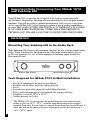
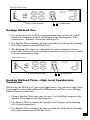
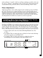
™
IWSub 10/10
& SubAmp 600
Ultra High-Performance In-Wall Subwoofer
and Separate Amplifier Module
Owner’s Manual
GET READY TO ROCK YOUR HOUSE!
Congratulations on your purchase of the remarkable
Definitive Technology in-wall subwoofer IWSub 10/10
and its matching Definitive Technology SubAmp 600.
This extraordinary In-Wall Subwoofer incorporates
Definitive Technology’s exclusive and effective
SuperCube™ technology for spectacular bass performance, the kind of musically accurate low end that’s
never before been available in a compact, nearly invisible
in-wall subwoofer. The IWSub 10/10 is specifically
designed to be powered by the matching Definitive
Technology SubAmp 600, which features two discrete
high power amplifiers to provide optimal power when
driving one or two IWSubs in your installation, whether
it is for whole-house distributed audio or dedicated music
or home theater applications.
Safety Precautions
CAUTION
RISK OF ELECTRIC SHOCK
DO NOT OPEN
CAUTION! To reduce the risk of electric shock and fire, do not remove the cover or back
plate of this device. There are no user serviceable parts inside. Please refer all servicing to
licensed service technicians. Avis: Risque de choc electricque, ne pas ouvrir.
CAUTION! The international symbol of a lightning bolt inside a triangle is intended to alert
the user to uninsulated “dangerous voltage” within the device’s enclosure. The international
symbol of an exclamation point inside a triangle is intended to alert the user to the presence
of important operating, maintenance and servicing information in the manual accompanying
the device.
CAUTION! To prevent electrical shock, match wide blade of plug to wide slot, fully insert.
Attention: Pour eviter les chocs electriques, introduire la lame la plus large de la fiche dans
la borne correspondante de la prise et pousser jusqu'au fond.
CAUTION! To reduce the risk of electrical shock, do not expose this equipment to rain
or moisture.
1.
2.
3.
4.
5.
6.
7.
Read Instructions—All safety and operating instructions should be read before operating the device.
Retain Instructions—The safety and operating instructions should be retained for future reference.
Heed Warnings—All warnings on the device and in the operating instructions should be adhered to.
Follow Instructions—All operating and safety instructions should be followed.
Water & Moisture—The device should never be used in, on or near water for risk of fatal shock.
Carts & Stands—The device should only be used on carts or stands recommended by the manufacturer.
Wall & Ceiling Mounting—The device should be mounted on a wall or ceiling only as recommended
by the manufacturer.
8. Ventilation—The device should always be located in such a way that it maintains proper ventilation. It
should never be placed in a built-in installation or anywhere that may impede the flow of air through its
heat sink.
9. Heat—Never locate the device near heat sources such as radiators, floor registers, stoves or other
heat-generating devices.
10. Power Supply—The device should only be connected to a power supply of the type described in the
operating instructions or as marked on the device.
11. Power Cord Protection—Power cables should be routed so they are not likely to be stepped on or
crushed by items placed on them or against them. Special attention should be paid to areas where the
plug enters a socket or fused strip and where the cord exits the device.
12. Cleaning—The device should be cleaned in accordance with manufacturer’s instructions.
13. Periods Of Non-Use—The device should be unplugged when not being used for extended periods.
14. Dangerous Entry—Care should be taken that no foreign objects or liquids fall or are spilled inside
the device.
15. Damage Requiring Service—The device should be serviced by licensed technicians when:
• The plug or power supply cord has been damaged.
• Objects have fallen or liquid spilled inside of the device.
• The device has been exposed to moisture.
• The device does not appear to be operating properly or exhibits a marked change in performance.
• The device has been dropped or the cabinet becomes damaged.
16. Service—The device should always be serviced by licensed technicians. Only replacement parts
specified by the manufacturer should be used. The use of unauthorized substitutions may result in
fire, shock, or other hazards.
2
•Unpacking Your IWSub 10/10 and SubAmp 600
• Please inspect your new equipment carefully. Notify your Definitive
Technology dealer immediately if you notice any damage or missing items.
• Record the serial numbers of your new equipment (usually found on the
rear panels). Note this information in the appropriate place on your Warranty
Card. Mail in your Warranty Card within 10 days of purchase.
• Keep the cartons and packing material. They will do the best job of
protecting your speakers if they need to be transported.
Important Note Concerning In-Wall Installation
The IWSub 10/10 is designed to be installed inside the walls of your home
quickly and easily. Because of its superb sonic performance, its installation
location within your room is very flexible. But your room is not like anyone
else’s room, and because of its unique size and shape will have its own requirements for optimal sonic performance. We recommend that you consult with the
Custom Installation Specialist at your Definitive Technology dealer regarding
your special needs or if you are at all uncertain about the best and safest way
to install your subwoofer.
• Before starting construction or modification of your walls or ceilings, you
should familiarize yourself with any applicable local fire and building codes.
• Speaker wire must be run inside your wall as part of the installation process
of in-wall loudspeakers. Plan the connection before you start your loudspeaker installation.
• Make sure the locations you select do not conceal studs, electrical wiring or
plumbing. Prior to installation, hold the speaker in your chosen location to
make sure it safely clears obstacles such as studs, corners, beams, lighting
fixtures and door/window frames. Your cutout must be at least 1" (25mm)
from adjoining walls or ceiling, internal studs or plumbing, and a minimum
of 5" above the floor or 1" above the top of the baseboard (whichever is
higher). Note that the frame around the inset loudspeaker extends 1" beyond
your cutout.
• It is highly recommended that you take advantage of the expertise
of a professional installation specialist.
3
Important Note Concerning Your IWSub 10/10
and SubAmp 600
Your IWSub 10/10 is specifically designed to be used in conjunction with
the Definitive Technology SubAmp 600 and should never be used with another
amplifier. You will not achieve optimal performance, and you may cause damage to your IWSub 10/10 if you attempt to power it using another amplifier or
receiver. BECAUSE OF THIS, THE IWSUB 10/10 WARRANTY IS VOIDED
IF AN AMPLIFIER OR RECEIVER OTHER THAN THE DEFINITIVE
TECHNOLOGY SUBAMP 600 IS USED TO DRIVE THIS SUBWOOFER.
Installation
Mounting Your SubAmp 600 In An Audio Rack
Your SubAmp 600 features side mounting brackets for use in professional audio
racks. When installing the SubAmp 600 in either professional audio racks or
in AV rack furniture, be sure to leave adequate ventilation space around the
SubAmp 600 unit.
Mounting Bracket
Mounting Bracket
Tools Required for IWSub 10/10 In-Wall Installation
•
•
•
•
•
•
•
Pencil for marking the location of installation.
Keyhole saw or utility knife for cutting drywall.
Level.
Screwdriver, preferably powered, with Phillips head bit.
Power drill with appropriate bit (optional, for starting wall cut).
Template (included: 143/8" x 197/8").
Gasket material (included).
1. The IWSub 10/10 is designed to be located between two vertical studs,
inside a space of 141/2"–151/2", with the long dimension of the speaker
oriented vertically. If your studs are spaced wider than this, you will have to
shim one side of the inner wall space to properly secure the speaker in a
141/2"–151/2" space.
4
Figure 1
Figure 2
2. Make certain to incorporate at least 11/4" of space above and below the area
within the inner wall space to make room for the IWSub’s locking arms.
3. With these measurement requirements in mind, place the template against
the inside edge of one of the studs. (Do not “center” the template if your
studs are wider than 141/2"–151/2".) Use a level to make certain the
template is straight and plumb. The outside edge of the template will
be your exact cutout size. [Figure 1]
4. Carefully cut the hole with the appropriate cutting tool for your wall material. Start the hole by drilling a hole on the inside of the template line (with
the drill bit touching the line). Use this hole to insert your saw or knife
and begin cutting. [Figure 2]
Figure 3
Figure 4
5. Before installing the speaker in the hole, apply the four long strips of
gasket material to the speaker: two pieces on each side of the speaker that
will come into contact with the studs. [Figure 3] Use the three shorter strips
of gasket material to pad the rear of the speaker against the back of the
exposed wall. [Figure 4]
5
Figure 5
Figure 6
6. Once you have cut the hole, fish your previously positioned wiring out
of the hole and connect your speaker. See the next section for detailed
hookup instructions. Make certain that you connect the wire from the
red terminal (+) of your SubAmp 600 to the red terminal (+) on your
speaker and the wire from the black terminal (-) of your SubAmp 600
to the black terminal (-) on your speaker. Be sure to maintain channel
consistency (use either channel one or channel two).
7. Place the subwoofer carefully into the hole [Figure 5]. Secure the sub
enclosure using the 6 screws provided. These screws go into the holes
in the front of the enclosure and angle back into the studs (or, if the space
between your studs was wider than 141/2"–151/2", into the shims). [Figure
6] Tighten all the screws on one side before installing and tightening the
screws on the other side.
8. Secure the locking arms at the top and bottom of the plastic frame
by turning the screws clockwise, taking care not to over tighten.
Making System Connections With Your
SubAmp 600
Recommended Hookup Method One
1. Use a Low (Line) Level RCA connection from your receiver’s LFE Out in
to the LFE Input of the SubAmp 600.
2. Use Speaker Wire to connect the top set of Sub Out Jacks on the SubAmp
600 to the terminals on the IWSub 10/10.
6
3. The SubAmp 600 features an Adjustable Crossover setting on its
front panel. This hookup bypasses the SubAmp 600’s Adjustable
Crossover feature.
Hookup Method One
RCA from Receiver
To Subwoofer
Hookup Method Two
1. Use a Low (Line) Level RCA connection from your receiver’s L and R
Line Level Outputs in to the L and R Input of the SubAmp 600. This
connection is “summed” within the SubAmp 600.
2. Use Speaker Wire to connect the top set of Sub Out Jacks on the SubAmp
600 to the terminals on the IWSub 10/10.
3. The SubAmp 600 features an Adjustable Crossover setting on its front
panel. This setting will work with this connection, giving you extra control
over your subwoofer settings.
Hookup Method Two
RCA from Receiver
To Subwoofer
Hookup Method Three—High Level Speakerwire
Connection
When using the IWSub 10/10 for stereo applications, you can feed it either Low
Level signals as described in Hook Up Methods One and Two, or use Hookup
Method Three described here.
1. Connect Speaker Wire from your receiver’s Left and Right outputs to the
Speaker Level Inputs on the SubAmp 600.
2. Use Speaker Wire to connect the Speaker Level Outputs of the SubAmp
600 to your loudspeakers.
3. Use Speaker Wire to connect the top set of Sub Out Jacks on the SubAmp
600 to the terminals on the IWSub 10/10.
7
4. The SubAmp 600 features an Adjustable Crossover setting on its front
panel. This setting will work with this connection, giving you extra control
over your subwoofer settings.
Hookup Method Three
To Speakers
From Receiver
To Subwoofer
Making Adjustments to Your SubAmp 600
The rear panel of your SubAmp 600 features a Remote Mini Plug Input and
Auto/Remote Slider Switch.
• Use this feature to connect your SubAmp 600 to the Remote Out of your
receiver. Moving the Slider Switch to “Remote” will enable your SubAmp
600 to then switch on when you power up your other equipment.
• If a remote connection is not used, this slider MUST be switched to “Auto”
in order for the SubAmp 600 to operate properly.
The front panel of your SubAmp 600 features Volume, Crossover and Phase
Adjustment controls.
Volume Adjustment
Use this setting to control the level (volume) of bass response. Begin with
the volume set at about the 11 o’clock position, and, once you have made all
your other settings, modify this setting for optimum volume and low distortion.
Remember: damage can occur to loudspeakers when an amplifier, regardless of
its wattage, is made to play at higher listening levels than its power can clearly
produce. This is usually beyond the “noon or 1 o’clock” position on the volume
control. If you hear distortion, TURN IT DOWN.
Crossover Adjustment
This control adjusts the frequency range over which your subwoofer operates. In
most situations, the middle range (11 – 2 o’clock) of this control will sound best.
Experiment and let your ears be the final judge. Turning the setting higher will
8
tend to add more “warmth” to the bass and lower midrange, possibly at the sacrifice of bass “tightness” and midrange clarity. Turning the setting down from the
recommended setting will make the bass and lower midrange sound “leaner.”
Phase Adjustment
Adjusting the Phase can be a little tricky. If you're in doubt, just leave the Phase
at 0 (zero). The best way to adjust the Phase is to get a friend to help you out.
Play music that features a good combination of bass notes and deep male vocals
at different frequencies. Have one person sit in the normal listening position
while the other person slowly rotates the Phase control until it reaches the position that produces the fullest bass sound across the bass spectrum.
Installing More Than One IWSub In Your Room,
Or One Each in Each of Two Rooms
Installing two IWSub 10/10s into the walls of your room, or one each in each of
two rooms, will allow you to achieve a mind-blowing amount of bass from subwoofers that take up no floor space! The SubAmp 600 has two separate high
power amplifiers for just this purpose. It is designed to drive one or two IWSub
10/10s with full performance and maximum power delivered to each subwoofer.
1. Connect inputs to the sub as described in Hookup Methods One, Two
or Three.
2. Use Speaker Wire to connect the top set of Sub Out Jacks on the SubAmp
600 to the terminals on one IWSub 10/10.
3. Use Speaker Wire to connect the bottom set of Sub Out Jacks on
the SubAmp 600 to the terminals on the other IWSub 10/10.
Multi-Sub Hookup
RCA from Receiver
Sub 1
Sub 2
9
Painting Your IWSub 10/10
The IWSub 10/10 is easy to paint. It virtually disappears into your room when
it is the same color as your wall. For best results, paint the grille and frame
separately prior to in-wall installation.
You Will Need:
• Paint of your choice (to make the job easier, we recommend spray painting
the grille).
• A paperclip (for removing the paintable grille).
• Masking tape.
• Paint mask (to cover unpaintable parts, supplied).
Preparing to Paint:
1. Separate the parts of the speaker. The grille can be removed simply by
carefully hooking it with a bent paperclip and pulling it gently away from
the frame. [Figure 7]
2. When painting the frame of the speaker, use the supplied paint mask to
carefully mask off the front of the speakers to protect the drivers and baffles
while painting [Figure 8]. You can do this while the speaker is already
installed in the wall (if, for instance, you’re repainting the room). If you do
not have the paint masks, carefully mask the speaker components using
paper and masking tape.
Figure 7
Figure 8
Painting the Frame:
1. Apply paint to exposed (unmasked) parts. Use two or more thin coats.
Spray painting is recommended.
10
2. When the paint is completely dry, remove the masking material.
Painting the Grille:
1. The grille of the IWSub 10/10 features an even, protective powder coating.
This powder coating is an ideal primer.
2. Grilles must be spray painted. Do not use a brush and paint. Thick, brushed
paint may clog the grille holes and impair performance.
3. After removing the grille by carefully hooking it with a bent paper
clip and pulling it gently away
from the frame, spray on two thin
coats of finish color. [Figure 9]
If you’re using a compressor and
spray gun, use the finest, most diffuse setting. Be careful not to fill
the holes in the grille with paint.
4. When paint is completely dry,
carefully reinstall the grille.
Figure 9
Troubleshooting Your IWSub
• If, after following these hookup and installation directions, you
experience difficulty, please double-check all wire connections.
• Check the setting of the “Auto/Remote” slider switch on the rear panel of
the SubAmp 600. If no remote connection is made, this switch MUST be
set to “Auto” in order for the SubAmp 600 to operate properly.
• Many amplifiers and receivers have sophisticated internal protection
circuitry. If for some reason your protection circuitry is tripped, turn
down your system’s volume level and wait five minutes before restarting
the system.
• If you are still having problems, please contact your authorized Definitive
Technology dealer for assistance.
11
Service
Service and warranty work on your Definitive Technology audio equipment will
be performed by your authorized Definitive Technology dealer. If, however, you
wish to return your equipment directly to us, please contact us first to describe
the problem you may be having and to allow us to give you return authorization
or suggest the location of the nearest factory service center. The address below is
the address of the Definitive Technology office only. UNDER NO CIRCUMSTANCES SHOULD EQUIPMENT BE SHIPPED TO OUR OFFICE OR
RETURNED WITHOUT CONTACTING DEFINITIVE TECHNOLOGY
FIRST TO OBTAIN RETURN AUTHORIZATION.
Definitive Technology
11433 Cronridge Drive
Suite K
Owings Mills, Maryland, USA 21117
410-363-7148
Email Definitive Technology at [email protected].
Visit us at www.definitivetech.com for more information and to
see the whole exciting line of Definitive Technology products.
12
IWSub 10/10 & SubAmp 600 Specifications
IWSub 10/10
Outer Dimensions:
Cut-out Size:
Rec. Assoc. Amp:
Frequency Response:
Nominal Impedance:
Driver Complement:
Enclosure:
Net Weight:
151/2" W x 21" H
143/8" W x 197/8" H
SubAmp 600
16 Hz – 200 Hz
4 ohms
One 10" long-excursion woofer
coupled to a 10" infrasonic radiator
Non-resonant sealed medite
enclosure
23 lbs.
SubAmp 600
One Channel Operation:
Two Channels Driven:
With Brackets, Feet removed:
Without Brackets, including Feet:
275 Watts
230 Watts each
37/16" H x 191/16" W x 95/8" D
311/16" H x 171/16" W x 95/8" D
When installing the SubAmp 600 in either professional audio racks or in
AVrack furniture, be sure to leave adequate ventilation space around the
SubAmp 600 unit. Ideally, we recommend leaving a single rack unit open
above and below the product.
Visit us at www.definitivetech.com
and learn about all our exciting products.
13
Limited Warranty:
5-Years for Drivers and Cabinets,
3-Years for Electronic Components
Definitive Technology warrants to the original retail purchaser only that this Definitive
Technology Loudspeaker Product (the “Product”) will be free from defects in materials and
workmanship for a period of five (5) years covering the drivers and cabinets, and three (3) years
for the electronic components from the date of the original purchase from a Definitive
Technology Authorized Dealer. However, this warranty will automatically terminate prior to
the expiration of five (5) years for the drivers and cabinets and three (3) years for the electronic
components if the original retail purchaser sells or otherwise transfers the Product to any other
party. The original retail purchaser shall hereinafter be referred to as “you.” Defective Products
must be shipped, together with proof of date of purchase, prepaid insured to the Authorized
Dealer from whom you purchased the Product, or to the nearest factory service center.
Product(s) must be shipped in the original shipping container or its equivalent; in any case the
risk of loss or damage in transit is to be borne by you. If, upon examination at the Factory or a
Definitive Technology Authorized Dealer, it is determined that the unit was defective in
materials or workmanship at any time during this Warranty period, Definitive Technology or
the Definitive Technology Authorized Dealer will, at its option, repair or replace this Product at
no additional charge, except as set forth below. All replaced parts and Product(s) become the
property of Definitive Technology. Product(s) replaced or repaired under this Warranty will be
returned to you, within a reasonable time, freight collect.
This Warranty does not include service or parts to repair damage caused by accident, misuse, abuse, negligence, inadequate packing or shipping procedures, commercial use, voltage in
excess of the rated maximum of the unit, cosmetic appearance of cabinetry not directly
attributable to defects in materials or workmanship, or service, or repair or modification of the
Product which has not been authorized by Definitive Technology. Definitive Technology makes
no Warranty with respect to its Products purchased from dealers or outlets other than
Definitive Technology Authorized Dealers. This Warranty is in lieu of all other expressed
Warranties. If this Product is defective in material or workmanship as warranted above, your
sole remedy shall be repair or replacement as provided above. In no event will Definitive
Technology be liable to you for any incidental or consequential damages arising out of the use
or inability to use the Product, even if Definitive Technology or a Definitive Technology
Authorized Dealer has been advised of the possibility of such damages, or for any claim by any
other party. Some states do not allow the exclusion or limitation of consequential damages, so
the above limitation may not apply to you.
All implied warranties on the Product are limited to the duration of this expressed
Warranty. Some states do not allow limitation on how long an implied Warranty lasts, so the
above limitations may not apply to you. This Warranty gives you specific legal rights, and you
also may have other rights which vary from state to state.
This product complies with the essential requirements of
EMC directives 89/336/EEC and 73/23/EEC (inclusive of
93/68/EEC) and carries the CE mark accordingly.
CYAT013009