1
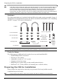
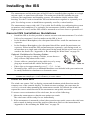
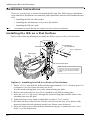
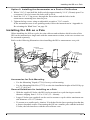
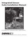
Integrated Sensor
Suite Installation Manual
For Vantage Pro2™ & Vantage Pro2 Plus™ Weather Stations
Davis Instruments, 3465 Diablo Avenue, Hayward, CA 94545 • 510-732-9229 • www.davisnet.com
Contents
Introduction ....................................................................................................... 1
Included Components and Hardware ................................................................ 1
Cabled ISS Assembly ........................................................................................ 7
Wireless ISS Assembly ..................................................................................... 9
Preparing the ISS for Installation .................................................................... 13
Installing the ISS ............................................................................................. 19
Installation Instructions ................................................................................... 20
Maintenance and Troubleshooting .................................................................. 25
Appendices ............................................................................................... 28
FCC Part 15 Class B Registration Warning
This equipment has been tested and found to comply with the limits for a Class B digital device, pursuant to Part 15
of the FCC Rules. These limits are designed to provide reasonable protection against harmful interference in a residential installation. This equipment generates, uses, and can radiate radio frequency energy and, if not installed
and used in accordance with the instructions, may cause harmful interference to radio communications.
However, there is no guarantee that interference will not occur in a particular installation. If this equipment does
cause harmful interference to radio or television reception, which can be determined by turning the equipment on
and off, the user is encouraged to try to correct the interference by one or more of the following measures:
•
Reorient or relocate the receiving antenna.
•
Increase the separation between the equipment and receiver.
•
Connect the equipment into an outlet on a circuit different from that to which the receiver is connected.
•
Consult the dealer or an experienced radio/TV technician for help.
Changes or modification not expressly approved in writing by Davis Instruments may void the warranty and void
the user's authority to operate this equipment.
FCC ID: IR2DWW6328
IC: 378810-6328
EC EMC Compliance
This product complies with the essential protection requirements of the EC EMC Directive 89/336/EC.
Integrated Sensor Suite Installation Manual
Rev. E, April 7, 2008
Document Part Number: 07395.249
For Vantage Pro2 Weather Stations # 6322, 6322C, 6323, 6327, 6327C, 6328
For Vantage Pro2 systems 6152C, 6162C, 6152, 6162, 6153, and 6163
®
™
Vantage Pro and Vantage Pro2 are trademarks of Davis Instruments Corp., Hayward, CA.
© Davis Instruments Corp. 2006. All rights reserved.
Information in this document subject to change without notice.
3465 Diablo Avenue, Hayward, CA 94545-2778 U.S.A.
510-732-9229 • Fax: 510-732-9188
E-mail: [email protected] • www.davisnet.com
Introduction
The Integrated Sensor Suite (ISS) collects outside weather data and sends the data to a
Vantage Pro2 console or Weather Envoy. Wireless and cabled versions of the ISS are
available, as well as Standard and Plus versions. The Wireless ISS is solar powered and
sends data to the console via a low-power radio. The Cabled ISS sends data and receives
power via the console cable.
The Standard version of the ISS contains a rain collector, temperature sensor, humidity
sensor and anemometer. In addition to the standard weather features, the ISS Plus adds a
pre-installed solar radiation sensor and an ultra-violet (UV) radiation sensor. Temperature
and humidity sensors are mounted in a passive radiation shield to minimize the impact of
solar radiation on sensor readings. The anemometer measures wind speed and direction
and can be installed adjacent to the ISS or apart from it. See “Locating the ISS and
Anemometer” on page 15 for siting guidelines.
On an ISS Plus, the additional solar and UV sensors are mounted next to the rain
collector cone. Solar and UV sensors are available separately to upgrade a standard ISS.
The Sensor Interface Module (SIM) contains the “brains” of the ISS and the radio
transmitter. The SIM is located on the front of the radiation shield in the SIM box. The
SIM collects outside weather data from the ISS sensors and then transmits the data to
your Vantage Pro2 console or Weather Envoy.
Included Components and Hardware
The ISS comes with all the components and hardware shown in the following
illustrations. If you purchased your ISS as part of a weather station package containing
the Vantage Pro2 console, additional components may be included in the package that are
not shown here.
Components
Debris Screen
(place inside cone
after installation)
Rain Collector
Solar Panel
(wireless
ISS only)
UV and Solar
Sensors
(ISS Plus Only)
Anemometer
Vane
Sensor
Mounting Shelf
(ISS Plus Only)
Control
Head
Drip
Ring
SIM
Housing
ISS Base
Anemometer
Arm
Wind Cups
Radiation
Shield
Anemometer Cable
40' (12.2 m)
Anemometer
Base
Metric Rain Adapter
Console Cable 100' (30 m)
(Cabled ISS Only)
1
Preparing the ISS for Installation
Note:
If the ISS is a Plus model and contains UV and solar sensors, do not touch the small white diffusers
on top of the sensors. Oil from skin reduces their sensitivity. If you are concerned that you have
touched the diffusers at any time during the installation, clean the UV diffuser using ethyl alcohol
with a soft cloth. When cleaning the UV diffuser, DO NOT use rubbing or denatured alcohols
because they can affect accuracy of the sensor readings. Ethyl alcohol can be procured through an
industrial or laboratory supply store. Clean the solar diffuser with a soft damp cloth.
Hardware
The following hardware is included with the ISS and weather station assembly. Some of
the hardware is optional based on how the ISS is assembled and installed. (See “Installing
the ISS” on page 19 for more information.)
U-Bolts
1/4" x 3" Lag Screws
1/4" Flat Washers
#4 x 1-1/8"
Machine Screw
1/4" Lock Washers
1/4" Hex Nuts
Backing Plate
#4 Tooth
Lock Washer
.05" Allen
Wrench
#4-40 Hex Nut
8" Cable Tie
Note:
3-Volt
Lithium
Battery
(wireless
models
only)
If any of the hardware components are missing or not included, contact Customer Service toll free
at 1-800-678-3669 about receiving replacement hardware or other components.
Tools for Setup
The following are additional tools required to set up and install the ISS:
• Small Phillips head screwdriver
• Scissors or wire-cutters
• Adjustable wrench or 7/16" wrench
• Compass or local area map
• Ballpoint pen or paper clip (or other small pointed object)
• Drill and 3/16" (5 mm) drill bit (if mounting on a vertical surface)
Preparing the ISS for Installation
Please follow the steps in the order they are presented. Each step builds on tasks
completed in previous steps.
Note:
2
Using a well-lit work table or work area to prepare the ISS for installation is recommended.
Preparing the ISS for Installation
The steps to prepare the ISS for installation are:
• Assemble the anemometer.
• Check the factory-installed sensor cable connections to the SIM.
• Connect the anemometer sensor cable to the SIM.
• Apply power to the ISS and test communication with the console.
• Change the Transmitter ID for wireless communication, if necessary.
Assemble the Anemometer
The anemometer measures wind direction and speed. The anemometer arm comes
partially assembled with the wind vane attached. The anemometer arm requires assembly
before it can be assembled with the rest of the ISS.
Please locate the following parts to prepare the anemometer:
• Anemometer arm (wind vane and cable already attached)
• Anemometer base
• Wind cups
• Allen wrench (0.05")
• #4 machine screw, #4 tooth-lock washer, #4 hex nut
Attaching Anemometer Arm to Base
1. Insert the anemometer arm into the base, sliding the cable through the notch in the
base as shown in illustration.
2. Be sure to line up the small hole in the arm with the holes in the base.
3. Insert the machine screw through the holes in the base and arm.
Insert
anemomter arm
into base
#4 Tooth
Lock Washer
Slide cable
through notch
Hex Nut
#4 x 1-1/8"
Machine
Screw
Important:
Press cable
firmly
into channel
3
Check SIM Sensor Connections
4. Slide the tooth-lock washer and hex nut onto the machine screw. Tighten the hex nut
while holding the screw with a Phillips head screwdriver to prevent it from turning.
5. Press the sensor cable firmly and completely into the zig-zagging channel in the base,
starting from the arm and progressing downward to the bottom of the base. Be sure to
press the cable into the channel at the bottom of the groove.
Note:
The pole can pinch or cause wear on the anemometer cable if the cable is not pressed completely into the channel at the bottom of the groove.
Attaching the Wind Cups
1. Push the wind cups up onto the anemometer’s stainless steel shaft.
2. Slide the wind cups up the shaft as far as possible.
Note:
Make sure to push the cups onto the stainless steel shaft as far up the shaft as possible.
Failure to do so will cause the anemometer to function improperly.
Push cups onto
stainless steel
shaft
Tighten set
screw with
Allen wrench
Attaching Wind Cups
3. Use the Allen wrench provided to tighten the set screw on the side of the wind cups.
The wind cups should drop slightly when you let go.
Note:
Ensure that the set screw is screwed in fully and very tight. Failure to do so will cause the
anemometer to function improperly.
4. Spin the wind cups.
If the wind cups spin freely, the anemometer is ready and can be set aside while you
prepare the rest of the ISS for installation.
Note:
If the wind cups don’t spin freely, take them off and repeat the wind cup installation process.
Check SIM Sensor Connections
The SIM is located in the housing on the front of the ISS station. The SIM contains all the
connections for the weather sensors of the ISS. The SIM is located in the housing on the
front of the ISS station. The SIM contains all the connections for the weather sensors of
the ISS. Follow the steps below to check the SIM and ensure that all sensors are
connected properly.
4
Check SIM Sensor Connections
Open the SIM Box
1. Locate the white box with the solar panel
containing the SIM on the front of the
ISS unit. The cabled model does not have
a solar panel.
2. Locate the white tab at the bottom center
of the SIM box cover.
3. Lift the tab away from the box while sliding the cover up.
Look on the side of the SIM box. The
box cover can be easily removed from
the box when the alignment indicator on
the cover is lined up with the alignment
indicator on the box
4. Lift the cover off the box, being careful
not to stress the solar panel cable when
removing the cover.
The SIM and sensor connectors are
visible once the SIM cover has been
removed.
Note:
See “SIM Board Display and Contents” on page 30 for information on locating the components
and points of interest on the SIM board.
Optional: Disconnect the solar panel
connection
The solar panel on the box cover is
connected to the SIM by a wire. If the
cover cannot be set aside while still
connected to the SIM box safely, it
should be disconnected from the SIM
box. To disconnect the solar power
connection:
1. Locate the brown connector for the
solar power wire.
2. Pull the connector outward off the
brown solar power tab. The solar
panel is no longer connected to the
SIM.
3. Set the SIM cover aside.
Check the Factory Installed Sensor Connections
1. Verify that the rain collector and temperature/humidity sensor cables are plugged into
the receptacles labeled RAIN and TEMP/HUM on the SIM.
2. If the station includes UV and/or solar radiation sensors, verify that the sensor cables
are plugged into the receptacles labeled UV and SUN on the SIM.
5
Check SIM Sensor Connections
Connect the Anemometer Cable to the SIM
1. Unwind the coil of cable enough to work with the anemometer.
Note:
Do not unwind the entire coil of anemometer cable at this time.
2. Pull the foam insert out of
cable access port in
between the cables and set
the foam insert aside.
3. Insert the anemometer
Sensor
cable end into the cable
Interface
Module
access port from beneath
(SIM)
the SIM box.
Slide the cable through the
cable access port with the
connector lever down.
4. Firmly insert the end of the
anemometer cable into the
connector labeled WIND.
Foam
The lever clicks into place.
Insert
5. Make sure that the cables
lie flat on the bottom the
cable access port.
6. Firmly insert the foam in
between the cables and at
the top of the cable access
Note: Only Plus models have UV and
solar cables already attached.
port, taking care to ensure
that the foam seals the
access port entirely, leaving no holes or gaps large enough for weather or insects.
Note:
If you are assembling a cabled station, wait to reinsert the foam until cable assembly is complete. See “Cabled ISS Assembly” on page 7.
Once the sensor connections have been checked and the anemometer cable has been
inserted, a connection between the ISS and the Vantage Pro2 console must be made.
7. Read the following instructions that best apply to your ISS and Vantage Pro2 assembly:
• See “Cabled ISS Assembly” on page 7 for assembling Vantage Pro2 weather stations that contain a cabled connection between the ISS and the console.
• See “Wireless ISS Assembly” on page 9 for assembling Vantage Pro2 weather stations that use a wireless connection to transmit and receive data.
6
Cabled ISS Assembly
The Cabled ISS system contains a cable for connecting the ISS to a Vantage Pro2 cabled
console. Once the anemometer has been installed and the sensors have been checked, a
cabled connection between the ISS and the console can be established. Follow the steps
below for powering the ISS and connecting to the console.
Applying Power
The 100' (30 m) console cable provides power to the ISS and is used to send data from
the ISS to the console. The console cable can be extended up to 1000' (305 m) in length
with extension cables purchased from Davis Instruments.
1. Locate the 100' console cable included with your system.
2. Pull the foam insert out of cable access port, if it has been reinserted, and set the foam
aside.
3. Insert the console connector cable end into the cable access port from beneath the SIM
box. Slide the cable through the cable access port with the connector tab down.
4. On the SIM, firmly insert one end of the 4conductor cable into the modular connector
From Cabled
Vantage Pro 2
located apart from the sensor connectors next to
Console
the battery insert. This connector is labeled
COMM.
Sensor
Interface
If you haven’t powered up the console yet, refer to
Module
(SIM)
the installation instructions in the Vantage Pro2
Console Manual and apply power to the console.
5. On the back of your console, insert the other end of the console cable into the modular
receptacle labeled “ISS.”
6. Firmly insert the foam in between the cables and at the top of the cable access port,
taking care to ensure that the foam seals the access port entirely, leaving no holes or
gaps for weather or insects. See the graphic on page 6 for more information on
inserting the foam insert.
Plugging the console cable into the console powers the ISS and establishes
communication between the ISS and the console. The ISS should immediately begin
collecting weather data and start sending the data to the console.
Verifying Communication with the Console
Use these steps to verify reception of ISS data at the Cabled Vantage Pro2 console and to
test the operation of the ISS sensors.
1. If the console is in Setup Mode, press and hold DONE until the Current Weather
screen displays.
Sensor readings from the ISS should display on the screen.
2. Near the center of the screen, look for the outside temperature.
3. Spin the wind cups to check wind speed, pressing WIND if necessary to alternate
between speed and direction in the compass rose.
4. Turn the wind vane and allow five seconds for the wind direction display to stabilize
before moving it again.
7
Troubleshooting Cabled ISS Communication
Approximately one minute after power-up the outside relative humidity reading
should be displayed on the console.
5. If the ISS contains a UV sensor and/or solar sensor, press 2ND and then press RAIN
YR for current ultraviolet readings or press 2ND then press RAIN DAY for solar
radiation readings.
The UV reading displays in the center of the console. The solar reading displays in the
bottom right corner of the console display. UV and solar readings should be zero or
close to zero if the ISS is inside. Zero is a valid reading. Dashes(--) are displayed if no
data comes from the sensors.
6. Current weather data displayed on the console confirms communication.
Once the ISS has been powered and the console has successfully received accurate
readings from all the sensors, prepare the ISS for installation. Continue on to
“Preparing the ISS for Installation” on page 13 for more information.
If the communication problems still exist between the cabled ISS and the console, see
“Troubleshooting Cabled ISS Communication” below.
To ease the installation process of ISS at a location, disconnect the console cable from
the SIM. Remove the foam and slide the cable out through access port. Once a
location for both the ISS and the console has been arranged, reinsert the cable through
the access port, into the console connector, and reinsert the foam.
Troubleshooting Cabled ISS Communication
If the console is not receiving sensor readings from the ISS, please try the following
troubleshooting procedures.
• Check the console to make sure it is being powered with the AC adapter supplied in
the Vantage Pro2 packaged box or three C batteries.
Note:
The supplied adapter is a five-volt positive center AC to DC adapter. Other adapters may not work if
the voltage or adapter type is different.
• Make sure the cable is firmly plugged into the ISS connector on the console.
• Make sure that the console cable is firmly plugged into the correct connector on the
SIM.
• Verify that all sensor cables are firmly plugged in.
• An LED indicator light on the SIM flashes each time the ISS transmits, which is
about once every 2.5 seconds. If the LED remains dark, there is a problem with the
ISS transmitter. Call Technical Support. See “Contacting Davis Instruments” on
page 27.
See “SIM Board Display and Contents” on page 30 for information on locating the LED
indicator light and the DIP switches.
Note:
If the LED is flashing rapidly, call Technical Support. See “Contacting Davis Instruments” on
page 27 for more information.
If the console is still not receiving readings, ensure that the console is in Setup Mode and
reboot the console by disconnecting the AC power adapter from the console and
removing the console batteries for at least 30 seconds. If the console is still not displaying
sensor readings from the ISS, please contact Davis Technical Support.
8
Wireless ISS Assembly
The ISS has a wireless connection to a Vantage Pro2 wireless console. Once the
anemometer has been installed and the sensors have been checked, the ISS must be
powered and a wireless communication channel must be established between the ISS and
the console. Follow the steps below for powering the ISS and establishing a connection to
the console.
• Applying Power to a Wireless ISS
• Verifying Communications with the Console
• Verifying Data from the ISS Sensors
• Troubleshooting ISS Reception
Applying Power to a Wireless ISS
1. Insert the 3-volt lithium battery into the SIM.
Once powered, the ISS immediately begins transmitting data to the console.
Be sure to match the “+” sign on the battery with the “+” sign on the SIM. See “SIM
Board Display and Contents” on page 30.
The SIM stores energy from the solar panel for power at night. The battery is an
alternative power source the SIM uses when it is depleted of energy.
Checking Transmitter ID
A Vantage Pro2 console can receive data from up
to eight different wireless stations. The default
Transmitter ID for the ISS and console is 1.
ON
1
2
In most cases it will not be necessary to change
the Transmitter ID. The console and ISS should
begin communicating automatically when power is applied.
Note:
3
4
Settings for Transmitter ID 1:
DIP Switch 1 = OFF
DIP Switch 2 = OFF
DIP Switch 3 = OFF
If it is necessary to change the Transmitter ID, remember to use the same ID for the ISS and console. See “SIM Board Display and Contents” on page 30 for locating the components and points of
interest on the SIM board.
Verifying Communication with the Console
1. Power the console if it does not already have power. Refer to the Vantage Pro2
Console Manual and apply power the console.
The console automatically enters Setup Mode when powered up.
2. If the console is not in Setup Mode, press and hold DONE then press the down arrow.
The message RECEIVING FROM... and STATION NO. followed by the Transmitter
IDs that the console detects displays on the console screen.
3. Look for the ISS Transmitter ID. The number 1 displays unless the Transmitter ID has
been changed. If the console displays the ISS Transmitter ID, the ISS is detected.
Note:
If the console does not display the number of the ISS Transmitter ID setting, see “Troubleshooting
Wireless ISS Reception” on page 10 for more information. It can take several minutes for the console to acquire and display all the available Transmitter IDs.
4. Press and hold DONE to view ISS data once the ISS Transmitter ID displays.
9
Verifying Data from the ISS Sensors
Verifying Data from the ISS Sensors
Use these steps to verify reception of ISS data at the wireless Vantage Pro2 console and to
test the operation of the ISS sensors.
1. Press and hold DONE until the Current Weather screen displays, if the console is in
Setup Mode.
Sensor readings from the ISS should display on the screen.
2. Near the center of the screen, look for the outside temperature.
3. Spin the wind cups to check wind speed, pressing WIND if necessary to alternate
between speed and direction in the compass rose.
4. Turn the wind vane, and allow 5 seconds for the wind direction display to stabilize
before moving it again.
Approximately one minute after power-up the outside relative humidity reading
should be displayed on the console.
5. If the ISS contains a UV sensor and/or solar radiation sensor, press 2ND and then
press RAIN YR for current ultraviolet readings or press 2ND then press RAIN DAY
for solar radiation readings.
The UV reading displays in the center of the console. The solar reading displays in the
bottom right corner of the console display. UV and solar readings should be zero or
close to zero if the ISS is inside. Zero is a valid reading — dashes are displayed if no
data comes from the sensors.
6. Current weather data displayed on the console confirms successful communication.
Once the ISS has been powered and the console has successfully received accurate
readings from all the sensors, prepare the ISS for installation. Continue on to “Preparing
the ISS for Installation” on page 13 for more information.
If the communication problems still exist between the wireless ISS and the console, see
“Troubleshooting Wireless ISS Reception.”
Troubleshooting Wireless ISS Reception
If the console isn’t displaying data from the ISS, perform the following steps:
1. Verify that the console is powered and is not in Setup Mode.
2. Make sure that all ISS sensor cables are firmly connected to the SIM and the ISS
battery is properly installed.
3. Walk around the room with the console, standing for a few moments in various
locations, to see if you are picking up signals from the ISS. Look on the screen’s lower
right corner. An “X” toggles on and off when the console receives a transmission.
4. If you do not see the “X” slowly blinking, no matter where you stand with the console,
put your ISS in Test Mode.
• The DIP switch #4 on the SIM is the Test Mode
Setting for Test Mode
ON
switch. Switch it to the ON position, using a ballDIP Switch #4 = ON
point pen or paper clip.
1
2
3
4
• An LED indicator light on the SIM flashes each
time the ISS transmits, which is about once every
2.5 seconds.
10
Troubleshooting Wireless ISS Reception
Note:
If the LED is flashing rapidly, call Technical Support. See “Contacting Davis Instruments” on
page 27 for more information.
5.
6.
7.
8.
Note:
See “SIM Board Display and Contents” on page 30 for information on locating the
components and points of interest on the SIM board.
If the LED remains dark, there is a problem with the ISS transmitter. Call Technical
Support. See “Contacting Davis Instruments” on page 27.
If the LED flashes repeatedly but your console isn’t picking up a signal anywhere in
the room, it could be related to one of the following causes:
• You changed the ISS Transmitter ID at the ISS or console, but not at both.
• Reception is being disrupted by frequency interference from outside sources.
Interference has to be strong to prevent the console from receiving a signal while in
the same room as the ISS. In high-interference environments, it may be preferable
to install the Cabled Vantage Pro2.
• There is a problem with the console.
If a problem with receiving the wireless transmission still exists, please contact
Technical Support. See “Contacting Davis Instruments” on page 27.
When you are finished testing wireless transmission, set DIP switch # 4 to OFF to take
the SIM out of Test Mode.
If the SIM is left in Test Mode, the blinking LED will significantly reduce ISS battery life.
Optional: Changing ISS Transmitter ID
Each wireless transmitting station, including the Integrated Sensor Suite (ISS), uses one
of eight selectable Transmitter IDs. DIP switches #1, 2 and 3 on the transmitter control
the ID — or channel — the station transmits on. DIP switch #4 is used for transmission
testing, not for the Transmitter ID.
Note:
The transmitter on the ISS and receiver on the console communicate with each other only when
both are set to the same ID.
The default Transmitter ID is 1 for both the ISS and the Vantage Pro2 console, and should
work fine for most situations. Change the Transmitter ID if any of the following issues
are true:
• Another Davis Instruments wireless weather station operating nearby already uses
Transmitter ID 1.
• Additional wireless transmitting stations have been purchased with the Vantage Pro2
or Vantage Pro2 Plus and one of the stations has been designated as Station No. 1
instead of the selected ISS.
On the ISS, the Transmitter ID is set using the DIP switches located on the Sensor
Interface Module (SIM). To access the SIM, open the SIM housing cover. See “Open
the SIM Box” on page 5.
11
Troubleshooting Wireless ISS Reception
ON
1
2
3
4
DIP Switches
Transmitter ID DIP Switches in Top-right Corner of SIM
To change to another ID, use a ballpoint pen or paper clip to toggle DIP switches #1, 2,
and 3. The settings for Transmitter IDs 1 - 8 are shown in the table below.
Set the Vantage Pro2 console to the same ID as the transmitters, as described in the
Vantage Pro2 Console Manual.
ID CODE
SWITCH 1
SWITCH 2
SWITCH 3
#1 (default)
off
off
off
#2
off
off
ON
#3
off
ON
off
#4
off
ON
ON
#5
ON
off
off
#6
ON
off
ON
#7
ON
ON
off
#8
ON
ON
ON
Using Multiple Transmitting Stations
This table shows the maximum number of each type of station that can be used with a
single Vantage Pro2 console. The console can receive signals from a total of up to
eight transmitters (stations).
.
Station Type
Maximum Number
Integrated Sensor Suite (ISS)
Anemometer Transmitter Kit*
Leaf & Soil Moisture/Temperature Station
1
1
2**
Temperature Station
8
Temperature/Humidity Station
8
*Replaces the ISS anemometer.
**Two are allowable only if both stations are only partially populated. For example, A network can either
have both a Leaf Wetness/Temperature station and a Soil Moisture/Temperature station, or it can have one
combined Leaf Wetness and Soil Moisture/Temperature station.
12
Preparing the ISS for Installation
Once all the sensors have been connected and communication between the ISS and the
console has been successfully established, continue to prepare the ISS unit for
installation. The steps for preparing the ISS for installation are as follows.
• Close the SIM Box
• Prepare the Solar Panel
• Prepare the Rain Collector
• Site the ISS and Anemometer
Close the SIM Box
To close the SIM box and continue assembling the ISS:
1. If the solar panel wire was disconnected during ISS assembly, reconnect the wire on
the SIM box cover to the solar panel tab on the SIM board.
Note:
See “SIM Board Display and Contents” on page 30 for information on locating the solar panel tab.
2. Look on the side of the SIM box. Match up the box cover alignment indicator with the
alignment indicator on the SIM box and place the cover against the box.
3. Slide the cover down until it snaps securely in place.
Prepare the Rain Collector
The tipping bucket is secured at the factory to protect it from
damage during shipping. To use the ISS properly, the bucket must be
released. To release the bucket:
1. Remove the rain collector cone from the ISS base by rotating the
cone counter-clockwise. When the cone’s latches line up with
openings in the base, lift the cone off the ISS base.
When new, the cone fits tightly in the base and may require extra
pressure to remove. Steady the ISS base between your knees
when removing the cone.
2. Carefully cut and remove the
plastic tie that holds the tipping
Tipping Bucket
bucket in place during shipping
(usually yellow in color).
3. On your console screen, look for
the DAILY RAIN display.
If the console is cabled to the ISS,
reconnect the cable and see if the
console is receiving rain readings.
Twist to Open
Cut the
plastic tie
13
Prepare the Rain Collector
4. While watching the daily rain display, tip the bucket until it drops to the opposite side,
then wait two seconds to see if the display registers a rain reading. Each tip indicates
0.01" of rain and may take up to a minute to register at the console. If the bucket is
tipped too quickly, the number on the console display may not change.
5. Temporarily reinstall the rain collector cone until you are ready to mount the ISS
outside. If you are installing the metric measurement adapter, do not reinstall the rain
collector cone.
Optional: Insert the Metric Measurement Adapter
The rain collector tipping bucket mechanism contains a standard measurement weight
magnet that takes measurements in 0.01''. The ISS hardware kit contains a metric adapter
that adjusts the weight of the tipping bucket mechanism so that it reports 0.2 mm metric
measurements for every tip of the bucket. To install the metric adapter:
1. Find the metric adapter included in the hardware.
2. Locate the magnet between the arms of the bucket.
3. Open the arms slightly with one hand while pulling the magnet out with the other.
Open plastic tipping mechanism arms, pull out magnet
4. Separate an end cap from one end of the magnet.
Separate magnet from one end cap
Insert magnet with other end cap into metric measurement adapter
14
Locating the ISS and Anemometer
5. Slide the magnet, exposed end of magnet first, into the open slot of the metric adapter.
6. Insert the metric adapter and magnet between the arms of the bucket, with the solid
side of the metric adapter facing up.
Open plastic arms to insert metric measurement adapter,
with adapter in “V” position
Note:
The above procedure converts the collector to 0.2 mm measurements. The console must be set
accordingly. See the Vantage Pro2 Console Manual for more information.
Locating the ISS and Anemometer
For the weather station to perform at its best, use these guidelines to select the optimum
mounting locations for the ISS and anemometer. Be sure to take into consideration ease
of access for maintenance, sensor cable lengths and wireless transmission range when
siting the station.
Note:
When selecting a location for installing your ISS, especially on a rooftop, make sure it is a location
far from power lines. Seek professional help if you uncertain about the safety of your installation.
General ISS Siting Guidelines
• Place the ISS away from sources of heat such as chimneys, heaters, air conditioners
and exhaust vents.
• Place the ISS at least 100' (30 m) away from any asphalt or concrete roadway that
readily absorbs and radiates heat in the sun. Avoid installations near fences or sides of
buildings that receive a lot of sun during the day.
• Ideally, place the radiation shield of the ISS 5' (1.5 m) above the ground in the middle
of gently sloping or flat, regularly mowed grassy or naturally landscaped area that
drains well when it rains. For areas with average maximum yearly snow depths over 3'
(0.9 m), mount the ISS 2' (0.6 m) above this depth.
• Never install the ISS where it will be directly sprayed by a sprinkler system because it
will adversely affect the readings.
• Avoid installations near bodies of water such as swimming pools or ponds.
• Do not locate the ISS under tree canopies or near the side of buildings that create “rain
shadows”. For heavily forested areas, site the ISS in a clearing or meadow.
• Site the ISS in a location with good sun exposure throughout the day if the ISS is
wireless or includes solar radiation or UV radiation sensors.
15
Locating the ISS and Anemometer
For agricultural applications (Important for evapotranspiration (ET) calculations):
• Install the ISS and anemometer as a single unit with the radiation shield 5'
(1.5 m) above the ground and in the middle of the farm between similar crop types
(i.e. two orchards, two vineyards or two row crops), if possible.
• Avoid areas exposed to extensive or frequent applications of agricultural chemicals
(which can degrade the sensors).
• Avoid installation over bare soils. The ET formula works best when the ISS is
installed over well-irrigated, regularly mowed grass.
• If the last three guidelines cannot be met, install the weather station at the edge of
the primary crop of interest.
Anemometer Siting Guidelines
• For best results, place the anemometer at least 7' (2.1 m) above surrounding obstructions such as trees or buildings that obstruct wind flow.
• If mounting on a roof, mount the anemometer at least 7' (2.1 m) above the roof apex
(when using a Mounting Tripod, install the anemometer at the very top of the pole).
• If mounting the ISS and the anemometer together, such as on a pole or a wooden post,
mount the anemometer so it is at least 12'' (0.3 m) above the top of the rain collector
cone for best results.
• The standard for meteorological and aviation applications is to place the anemometer
33' (10 m) above the ground. Seek professional help for this type of installation.
• The standard for agricultural applications is to place the anemometer 6' (2 m) above
the ground. This is important for evapotranspiration (ET) calculations.
Note:
For roof mounting, and ease of installation, we recommend using the optional mounting tripod
(#7716). For other installations, use the Mounting Pole Kit (#7717).
Note:
For more detailed siting suggestions, see Application Note #30 on the Davis Support web site
(http://www.davisnet.com/support/weather).
16
Locating the ISS and Anemometer
Optional: Anemometer Cable Length Considerations
• All Vantage Pro2 stations
include a 40' (12 m) cable to go
between the ISS and the
anemometer. This can be
extended up to 540' (165 m)
using optional extension cables
purchased from Davis
Instruments.
• If most of the anemometer cable
length is unused, the coiled cable
length can be stowed once the
anemometer and ISS have been
installed on a site. Attaching the
anemometer cable to the
mounting pole using the supplied
cable tie is the recommended
option.
Anemometer
Cable
Cable Tie
Keep the anemometer cable
coiled if possible during the ISS
and anemometer assembly so that it is easily stowed once installation is complete.
• The Cabled Vantage Pro2 includes a 100' (30 m) cable to go between the console and
the ISS. This can be extended up to 1000' (300 m) using optional cables.
Optional: Wireless Transmission Considerations
The range of the radio transmission depends on several factors. Try to position the
transmitter and the receiver as close as possible for best results.
Typical maximum ranges include:
• Line of sight: 1000' (300 m).
• Under most conditions: 200 - 400' (60 - 120 m).
Other range and transmission considerations include:
• Range may be reduced by walls, ceilings, trees, foliage, a metal roof or other large
metal structures or objects such as aluminum siding, metal ducts, and metal
appliances, such as refrigerators, televisions, heaters, or air conditioners.
• Frequency interferers also reduce transmission distance. Cordless phones (900 Mhz)
are a common example of frequency interference.
• Transmission between wireless units may be obscured by something unidentifiable, or
by some obstacle that can’t be worked around.
• For best results, orient the ISS antenna and the console antenna so that the orientation
and angles of the antennas are parallel to each other.
17
Locating the ISS and Anemometer
(( (
(( (
If your ISS is directly overhead,
the orientation illustrated
here might work best.
For best reception, orient antennas
so they are parallel to each other.
• If possible, align the pivot joints of both the ISS and the console antennas so that they
are facing each other for maximum signal strength.
• The ISS and console antennas do not rotate in a complete circle. Avoid forcing the
antennas when rotating it.
• Turn the gain on to improve reception of a weak signal. Refer to the Vantage Pro2
Console Manual for information on setting the console gain.
• Consider using a Wireless Repeater (#7626 or #7627) or Long-Range Wireless
Repeater (#7653 or #7654) to strengthen the signal or to increase the distance between
the ISS and the console.
Testing Wireless Transmission at ISS Location
After a suitable place has been found for the wireless ISS, it is very important to test
reception from the installation location before permanently mounting it there.
1. Set the ISS in the desired installation location.
2. Set the console in the desired location.
3. Press and hold TEMP and press HUM to display statistical and reception diagnostics
on the console.
• It’s a good idea to test the console’s reception anywhere that you might want to use
or mount it now or in the future. Take your time. If you aren’t picking up a strong
signal where you intend to place your console, try rotating the antenna on the console and ISS or try moving the console and ISS to different positions.
• Irregular terrain in the area may interfere with the signal. For example, if the ISS is
mounted downhill from the console, the ground may block a large percentage of
the transmitted signal.
4. Press and hold DONE to return to the Current Weather Mode when finished testing.
Note:
18
See the Troubleshooting section of the Vantage Pro2 Console Manual for information on how to
check wireless signal strength and for more information on troubleshooting reception problems.
Installing the ISS
The anemometer and the main part of the ISS can be installed either together as a single
unit on a pole, or apart from each other. The main part of the ISS includes the rain
collector, the temperature and humidity sensors, the radiation shield, and the SIM
housing. Use the U-bolts to install the ISS and anemometer together or separately on a
pole. Use the lag screws to install them separately on a flat, vertical surface.
The anemometer comes with a 40' (12 m) cable for flexibility in configuring the system
to monitor wind conditions. For example, the anemometer could be mounted at the
highest point of a roof, and the ISS could be mounted on a fence closer to ground level.
General ISS Installation Guidelines
•
Install the ISS as level as possible to ensure accurate rain measurements. Use a bubble level or carpenter’s level to make sure the ISS is level.
• In the Northern Hemisphere, the solar panel should face south for maximum sun
exposure.
• In the Southern Hemisphere, the solar panel should face north for maximum sun
exposure. Either install the ISS and anemometer separately, each facing north, or
mount them as a single unit with solar panel facing north and the wind vane re-oriented to the South. See “Appendix A: Re-orienting the Wind Vane” on page 28.
Optional: Guidelines for Securing Cables
• To prevent fraying or cutting of cables, secure them so
they will not whip about in the wind.
• Secure cable to a metal pole using cable ties or by wrapCable Tie
ping tape around both the cables and the pole.
Cable Clip
• Place clips or ties approximately every 3' – 5' (1 – 1.6 m).
• Mounting clips, cable ties or additional hardware not included with your station can
be easily obtained at a hardware or electronics store.
Note:
Do not use metal staples or a staple gun to secure cables. Metal staples — especially when
installed with a staple gun — have a tendency to cut the cables.
Orient the Wind Vane
The wind vane rotates 360° to display current and dominant wind directions on the
compass rose of the console display. To obtain accurate readings, the vane must be
correctly oriented when mounting the anemometer outside. By default, the wind vane
reports the correct wind direction if the anemometer arm points true north.
To ensure correct orientation of the wind vane, do one of the following:
1. Mount the anemometer so that the arm points true north.
The wind vane will be ready for use immediately.
2. If the anemometer is mounted so that it does not aim true north, remove the wind vane
and re-attach it aiming toward the preferred direction. Refer to the instructions in
“Appendix A: Re-orienting the Wind Vane” on page 28.
19
Installing the ISS on a Flat Surface
Installation Instructions
There are several ways to mount and install the ISS unit. The following are installation
types that Davis Instruments recommends. Individual ISS locations and installations may
vary.
• Installing the ISS on a flat surface
• Installing the Anemometer on a post or flat surface
• Installing the ISS on a pole
Note:
All installations require that the rain collector cone be removed for assembly.
Installing the ISS on a Flat Surface
Refer to the following illustration to install the ISS on a post or flat, vertical surface.
1/4" Flat Washers
Anemometer Base
1/4" Lock Washers
1/4" x 3" Lag Screws
Backing Plate
1/4" x 3"
Lag Screws
40’ of Anemometer Cable
Note: Typically the anemometer and rain
collector are mounted on opposite sides
of the post. They are shown mounted on
adjoining sides to clarify the installation
details.
Option 1: Installing the ISS on a Post or Flat Surface
1. With a 3/16" (5 mm) drill bit, drill two holes approximately 2-1/8" (54 mm) apart. Use
a carpenter’s level to ensure the holes are level.
Use the metal backing plate as a guide when marking the holes.
2. Remove the rain collector cone if it is installed on the ISS mounting base.
3. Insert the 1/4" x 3" lag screws through the metal backing plate and the holes in the
mounting base into the post.
4. Tighten the lag screws using an adjustable wrench or 7/16" wrench.
5. Re-attach the rain collector cone. Set the cone back on the base so its latches slide
downward into the latch openings on the base. Rotate cone clockwise.
6. Place the debris screen (shown in the illustration on page 1) inside the cone, “feetdown” over the funnel hole.
20
Installing the ISS on a Pole
Option 2: Installing the Anemometer on a Post or Flat Surface
1. With a 3/16" (5 mm) drill bit, drill two holes approximately 2-1/8" (54 mm) apart. Use
a carpenter’s level to ensure the holes will be level.
2. Insert the 1/4" x 3" lag screws through the flat washers and the holes in the
anemometer mounting base into the post.
3. Tighten the lag screws using an adjustable wrench or 7/16" wrench.
If the anemometer arm is not pointing north, follow the instructions in “Appendix A:
Re-orienting the Wind Vane” on page 28.
Installing the ISS on a Pole
When installing the ISS on a pole, the rain collector and radiation shield section of the
ISS can be mounted as a single unit with the anemometer section, or the two sections can
be mounted separately.
Refer to the following illustration when installing the ISS or anemometer on a pole.
1/4" Hex Nut
1/4" Lock Washer
Nut Plate
1/4" Flat Washer
1/4" Lock Washer
1/4" Hex Nut
U-Bolts
Rain Collector
Mounting Base
Anemometer
Mounting Base
Accessories for Pole Mounting
• Use the Mounting Tripod (#7716) for easy roof-mounting.
• Use the Mounting Pole Kit (#7717) to raise the installation height of the ISS by up
to 37.5" (0.95 m).
General Guidelines for Installing on a Pole
• With the supplied U-bolts, the ISS can be mounted on a pole having an outside
diameter ranging from 1-1/4" to 1-3/4" (32 – 44mm).
• Larger U-bolts (not supplied) can be used to mount to a pole with a maximum outside diameter of 2-1/2" (64mm).
• To mount on a smaller pole, obtain a U-bolt that fits the base openings but that has
a shorter threaded section. If mounting the ISS on a smaller pole with the included
U-bolts, the bolt interferes with the rain collector cone.
21
Installing the ISS on a Pole
Guidelines for Installing the ISS on a Pole
• When mounting both sides together, remember that whichever side of the ISS is
mounted first, the U-bolt from the opposite side must also be placed around the
pole before tightening the U-bolts. (If it is not, there is no way to slide it in later.)
• In each side’s mounting base, there is a groove to accommodate the other’s U-bolt.
• Once the two sides of the ISS have been loosely mounted together on the pole,
swivel the unit to the correct direction and then tighten the hex nuts. The desired
height can also be achieved by sliding the ISS vertically.
Option 1: Installing ISS and Anemometer Together
Try to install the ISS so the anemometer arm is aiming north. If the arm doesn’t point
north, re-orient the wind vane. See “Appendix A: Re-orienting the Wind Vane” on
page 28.
1. Place the U-bolt for the anemometer around the pole so that its round end fits in the
top groove of the side of the rain collector side’s plastic mounting base. The groove is
right above two large holes.
2. While holding the mounting base of the rain collector against the pole, place the two
ends of the remaining U-bolt around the pole and through the two holes in the base.
3. Slide the metal backing plate over the bolt ends as they stick out over the rain collector
base. Secure the backing plate with a lock washer and hex nut on each of the bolt ends
as shown previously.
Note:
Do not tighten the hex nuts yet. Leave the hex nuts loose to swivel the ISS base on the pole.
4. The two ends of the anemometer’s U-bolt should now be pointing away from the
mounted rain collector side. Slide the anemometer’s mounting base over the
protruding bolt ends. Place a flat washer, a lock washer and a hex nut on each of the
bolt ends as shown above. Do not tighten the nuts yet.
5. Raise the ISS unit to the desired height on the pole and swivel it so the anemometer
arm is pointing north.
6. Using an adjustable wrench or 7/16" wrench, tighten all four hex nuts until the ISS is
firmly fastened on the pole.
7. Re-attach the rain collector cone by setting the cone back on the base so its latches
slide downward into the latch openings on the base, then rotate the cone clockwise.
8. Place the debris screen (shown in the illustration on page 1) inside the cone, “feetdown,” over the funnel hole. When installing the ISS as a single unit, we recommend
tucking the coil of anemometer cable between the rain collector cone and the ISS base.
Option 2: Installing ISS Only
1. While holding the mounting base against the pole, place the two ends of a U-bolt
around the pole and through the two holes in the base.
2. Slide the metal backing plate over the bolt ends as they stick out toward the rain
collector cone. Secure the backing plate with a washer, a lock washer, and a hex nut on
each of the bolt ends. Do not tighten the nuts yet.
For the wireless ISS, swivel the ISS base so the solar panel is facing south (in the
Northern Hemisphere), or north (in the Southern Hemisphere).
22
Finishing the Installation
3. Tighten the hex nuts using an adjustable wrench or 7/16" wrench.
4. Re-attach the rain collector cone.
Set the cone back on the base so its latches slide downward into the latch openings on
the base. Rotate the cone clockwise.
5. Place the debris screen (shown in the illustration on page 1) inside the cone, “feetdown,” over the funnel hole.
Option 3: Installing Anemometer Only
1. While holding the mounting base against the pole, place a U-bolt around the pole and
through the two holes in the base.
2. Place a flat washer, a lock washer and a hex nut on each of the bolt ends.
3. Swivel the anemometer until the arm is pointing north.
If the anemometer arm is not pointing north, go to “Appendix A: Re-orienting the
Wind Vane” on page 28 after tightening the hex nuts.
4. Using an adjustable wrench or 7/16" wrench, tighten the hex nuts.
Finishing the Installation
Level the Solar and UV Sensors
If you have a Vantage Pro2 Plus station that includes a solar radiation or UV sensor, use
the bubble level on the sensors as a guide to verify that the sensors are level.
Adjust the level by tightening or loosening the screws that hold each sensor onto the
shelf.
Note:
If you are installing the solar or UV sensors separately, see the Sensor Mounting Shelf installation
manual and the Solar Radiation and UV Sensor installation manuals for more information.
Clearing Data Collected During Testing and Installation
Now that the ISS is mounted outside, any data that was collected in the Vantage Pro2
console during testing and mounting can be cleared.
To clear all the collected data on the console:
1. Press WIND so that graph icon appears adjacent to the wind data on the display.
Confirm that wind speed is displayed on the compass rose.
2. Press 2ND, then press and hold CLEAR for at least six seconds and until you see
“CLEARING NOW” in the console ticker display.
Additional Mounting Options
Extending Wireless Transmission Range
Optional repeater stations can be used to extend the wireless transmission range.
• Wireless Repeater, AC-Powered (#7626)
• Wireless Repeater, Solar-Powered (#7627)
• Long-Range Wireless Repeater, AC-Powered (#7653)
• Long-Range Wireless Repeater, Solar-Powered (#7654)
23
Additional Mounting Options
Extending the Console Cable (Cabled ISS Only)
A Cabled ISS can be extended up to 1000' (300 m) away from the console by using Davis
Instruments extension cables (#7876).
Relocating the Anemometer
Using Extension Cables:
Note:
Not all cables are compatible with your Vantage Pro2 system. To be sure they will work, order Davis
extension cables from your dealer or directly from Davis Instruments.
The Anemometer can be extended further than 40' from the ISS by using Davis
Instruments extension cables (#7876).
Be aware that the maximum measurable wind speed reading decreases as the total length
of cable from the anemometer to the ISS increases.
Note:
If the cable length is greater than 540' (165m), the maximum measurable wind speed may be less
than 100 MPH (161 km/h).
Using the Anemometer Transmitter Kit (Wireless ISS Only)
Use the Anemometer Transmitter Kit (#6332) to add an independent wireless transmitter
to the anemometer. The kit allows the anemometer to function as a transmitter station
sending wind data directly to the console, instead of transmitting via the ISS.
Remote Mounting the Solar Radiation and UV Sensors
The solar radiation and UV sensors have a 3' (0.9 m) cable. If you wish to install these
sensors away from the ISS, you can extend the length of the sensor cables up to 125' (38 m)
with Davis Instruments extension cables (#7876).
Optional Wireless Stations
You may use our optional wireless sensor stations to collect weather measurements,
without the inconvenience of routing cables.
• Wireless Temperature Station (#6372)
• Wireless Temperature/Humidity Station (#6382)
• Wireless Leaf & Soil Moisture/Temperature Station (#6345)
For more details, please visit our website or see the most recent Davis Precision Weather
Instruments catalog.
24
Maintenance and Troubleshooting
Maintaining UV and Solar Radiation Sensors
If the ISS is a Plus model and contains UV and solar radiation sensors, do not touch the
small white diffusers on top of the sensors. Oil from skin reduces their sensitivity. If you
are concerned that you have touched the diffusers at any time, clean the UV diffuser
using ethyl alcohol with a soft cloth. When cleaning the UV diffuser, DO NOT use rubbing or denatured alcohols because they can affect accuracy of the sensor readings. Ethyl
alcohol can be procured through an industrial or laboratory supply store. Clean the solar
diffuser with a soft damp cloth.
Due to the sensitivity of ultraviolet and solar radiation sensors it is common practice for
manufacturers to recommend re-calibration after a period of time. Users demanding high
accuracy typically recalibrate their sensors annually. Here at Davis Instruments, we have
seen less than 2% drift per year on the readings from these sensors.
Contact Technical Support about returning your sensor for calibration. See “Contacting
Davis Instruments” on page 27.
Cleaning the Radiation Shield
The outer plating of the radiation shield should be cleaned when there is excessive dirt
and build-up on the plating. Use a damp cloth to clean the outer edge of each ring.
Note:
Spraying down or using water excessively to clean the radiation shield can damage the sensitive
sensors or alter the data and readings the ISS is transmitting.
Check the radiation shield for debris or insect
nests at least once a year and clean when
necessary. A buildup of material inside the
shield reduces its effectiveness and may cause
inaccurate temperature and humidity readings.
To thoroughly clean the radiation shield:
1. Remove the rain collector cone.
2. Using a Phillips head screwdriver, loosen
the three 4'' (~100mm) screws holding the
radiation shield plates together.
3. Taking care to maintain the order in which
the five plates are assembled, separate the
plates as shown and remove all debris from
inside the shield.
4" Screw
(3)
Lock
Washer
Flat
Washer
Rain Collector Base
Plates
Temp/Humidity
Sensor Plate
25
Troubleshooting
Note:
For some models of the ISS, the order in which the five radiation shield plates are assembled may
be slightly different than the order shown in the figure on page 25. For this reason, ensure that you
always reassemble the plates in the same order in which they were disassembled.
4. Reassemble the plates in the same order in which they were disassembled, and fasten
them together using a Phillips head screwdriver to tighten the 4” screws, as shown in
the illustration.
Cleaning the Rain Collector Cone
To maintain accuracy, thoroughly clean the rain collector several times a year.
Note:
Cleaning the rain collector and tipping buckets my cause false rain readings. Unplug the RAIN sensor from the SIM before cleaning so that no inaccurate readings are logged, or clear the weather
data that was logged on the Vantage Pro2 console after cleaning is complete. See your Vantage
Pro2 Console Manual for instructions on clearing weather data.
1. Separate the cone from the base by turning it counter-clockwise.
2. Use soapy water and a soft cloth to remove any debris from the cone, cone screen, and
tipping bucket.
3. Use pipe cleaners to clear the funnel hole in the cone and drain screens in the base.
4. When all parts are clean, rinse with clear water.
5. Re-attach the cone and replace the debris screen.
Troubleshooting
If a Sensor Functions Intermittently
Carefully check all connections from the sensor to the ISS. See “Check SIM Sensor
Connections” on page 4.
Loose connections account for a large portion of potential problems. Connections should
be firmly seated in receptacles and plugged in straight. To check for a faulty connection,
try jiggling the cable while looking at the display. If a reading displays intermittently on
the console as the cable is jiggled, the connection is faulty. Try removing and then reinstalling the cable to correct the faulty connection. If the sensor still functions intermittently contact Technical Support. See “Contacting Davis Instruments” on page 27.
Most Common Rain Collector Problem
If the rain collector seems to be under-reporting rainfall, remove the rain collector cone to
clean the tipping bucket and clear out any debris. Make sure the cable tie around the
tipping bucket has been cut and removed.
Most Common Anemometer Problems
“The anemometer head is tilted when I mount the anemometer.”
With the Allen wrench provided in the supplied hardware, loosen the screws
holding the anemometer head on the arm. (The screws are on the bottom of the
anemometer head, by the wind cups.) Turn the anemometer head so it is straight
and then tighten the screws.
26
Troubleshooting
“The wind cups are spinning but my console displays 0 mph.”
The signal from the wind cups may not be making it back to the display. Remove
the cups from the anemometer (loosen the set screw). Put the cups back onto the
shaft and make sure to slide them up the shaft as far as possible. Check your cables
for visible nicks and cuts. Look for corrosion in the WIND connector on the SIM
and on splices in the cable. If using an extension cable, remove it and test using
only the anemometer cable. Contact Technical Support and ask for a wind test
cable if the problem has not been resolved.
Note:
If the anemometer is sending no data, the wind display indicates 0 speed and a orth direction.
“The wind direction is stuck on north, or displays dashes.”
It is likely that there is a short somewhere between the wind vane and the display.
Check the cables for visible nicks and cuts. Look for corrosion in the “WIND” jack
on the SIM and on splices in the cable (if any). If possible, remove any extensions
and try it with the anemometer cable only. If none of these steps get the wind
direction working, contact Technical Support and ask for a wind test cable.
“The wind cups don’t spin or don’t spin as fast as they should.”
The anemometer may be located where wind is blocked by something, or there may
be friction interfering with the cups’ rotation. Remove the wind cups (loosen the set
screw) and clear out any bugs or debris. Turn the shaft the cups rotate on. If it feels
gritty or stiff, contact Davis Technical Support.
Note:
Do not lubricate the shaft or bearings in any way. When replacing the cups, make sure they are not
rubbing against any part of the anemometer head.
“Readings aren’t what I expected them to be.”
Comparing data from your ISS to measurements from TV, radio, newspapers, or a
neighbor is NOT a valid method of verifying your readings. Readings can vary
considerably over short distances. How you site the ISS and anemometer can also
make a big difference. If you have questions, contact Technical Support.
Contacting Davis Instruments
If you have questions about the ISS or Vantage Pro2 system, or encounter problems
installing or operating the weather station, please contact Davis Technical Support.
Note:
Please do not return items to the factory for repair without prior authorization.
(510) 732-7814 – Technical Support phone, Monday – Friday, 7:00 a.m. – 5:30 p.m.
Pacific Time.
(510) 670-0589 – Technical Support Fax.
[email protected] – E-mail to Technical Support.
[email protected] – General e-mail.
www.davisnet.com – Download manuals and specifications from the Support section.
Watch for FAQs and other updates. Subscribe to the e-newsletter.
27
Appendices
Appendix A: Re-orienting the Wind Vane
•
•
•
•
The Vantage Pro2 station is configured to register wind direction correctly if the
anemometer points to true north. If the anemometer shaft cannot be mounted to
point to true north, use the following instructions to correct the wind vane
orientation.
Do not rely on a compass unless it is properly calibrated. In North America there
can be up to 15° variation between true north and a raw compass reading.
Correct the wind direction readings by calibrating the wind direction in the Vantage Pro2 console. See the Vantage Pro2 Console Manual for information.
To orient the wind vane accurately, look at the console display. Have another person watch the console display while orienting the wind vane.
Also, re-orient the wind vane before the anemometer is installed if the direction
in which the anemometer will be installed is already known.
To re-orient the wind vane:
1. Loosen the wind vane set screw.
2. Pull the vane directly up and off the steel shaft on
which it turns.
3. Press WIND on the console to display current wind
direction in degrees.
4. Use a reliable map, properly calibrated compass or a
landmark to determine which direction is true south.
5. Slowly turn the stainless-steel wind direction shaft
Wind Direction Chart
with your fingers. Stop turning when the display
reaches 180° obtained in step 3.
6. Allow the wind direction display approximately 5 seconds to stabilize after the shaft
is turned. Turn the shaft, wait, and turn it again until 180° is displayed on the console.
7. Being careful to keep the stainless-steel shaft from turning, place the wind vane on
top of shaft with the vane’s nose pointing south.
8. Slide the wind vane down the shaft as far as it will go.
9. Use the Allen wrench provided to tighten the set screw on the side of the wind vane.
10.Test the anemometer by pointing the wind vane in any direction and making sure the
console displays the correct wind direction. Remove and re-adjust the vane if it does
not. Allow the wind direction display approximately 5 seconds to stabilize after
turning the shaft.
28
Appendix B: Specifications
Tighten set screw
with Allen wrench
Installing Wind Vane on Anemometer Shaft
11. Test the anemometer by pointing the wind vane in any direction and making
sure the console displays the correct wind direction. Remove and re-adjust the
vane if it does not. Allow the wind direction display approximately 5 seconds
to stabilize after turning the shaft.
Appendix B: Specifications
Complete specifications for the ISS and other products are available in the Weather
Support section of our website at www.davisnet.com.
Cabled ISS
Temperature range: . . . . . . . . . . . . . . . . -40 to 150° Fahrenheit (-40 to 65° Celsius)
Power input: . . . . . . . . . . . . . . . . . . . . . Console Cable from Vantage Pro2 console Optional
Vantage Pro2 AC power adapter
Wireless ISS
Temperature range: . . . . . . . . . . . . . . . . -40 to 150° Fahrenheit (-40 to 65° Celsius)
Transmission frequency: . . . . . . . . . . . . 902 - 928 MHz FHSS for North America
868.0 -868.6 MHz FHSS for overseas versions: EU, UK,
and OV
Transmitter ID codes: . . . . . . . . . . . . . . 8 user-selectable
License: . . . . . . . . . . . . . . . . . . . . . . . . . low power (less than 8 mW), no license required
Primary power: . . . . . . . . . . . . . . . . . . . Solar power – Davis solar charger
Backup power: . . . . . . . . . . . . . . . . . . . . CR-123A 3-volt lithium battery (8 months without sunlight- greater than 2 years depending on solar charging)
Alternate power . . . . . . . . . . . . . . . . . . . AC power adapter
ISS Weather Variable Update Intervals
(Transmitter ID Dependent)
Wind speed: . . . . . . . . . . . . . . . . . . . . . 2.5 to 3 seconds
Wind direction: . . . . . . . . . . . . . . . . . . . . 2.5 to 3 seconds
Accumulated rainfall: . . . . . . . . . . . . . . . 10 to 12 seconds
Rain rate: . . . . . . . . . . . . . . . . . . . . . . . . 10 to 12 seconds
Outside temperature: . . . . . . . . . . . . . . . 10 to 12 seconds
Outside humidity: . . . . . . . . . . . . . . . . . . 50 seconds to 1 minute
Ultraviolet radiation: . . . . . . . . . . . . . . . . 50 seconds to 1 minute
Solar radiation: . . . . . . . . . . . . . . . . . . . 50 seconds to 1 minute
29
SIM Board Display and Contents
SIM Board Display and Contents
2
1
3
4
5
+ -
6
7
SENSOR
INTERFACE
MODULE
UV
12
SUN
RAIN
WIND
TEMP
HUM
11
10
9
8
1
Solar Panel Tab
7
Test LED
2
AC Adapter Socke t
8
Temperature/Humidity Sensor Connector
3
Battery Socket
9
Wind Sensor Connector
4
Cabled Connection
10 Rain Sensor Connector
5
Transmitter ID DIP Switch
11 Solar Radiation Sensor Connector
6
Test DIP Switch
12 UV Sensor Connector
30