1
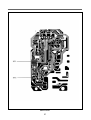
PRINTED CIRCUIT BOARD
1. CIRCUIT CHECK PROCEDURE
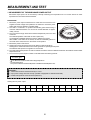
1. Low Voltage Transformer check
• The low voltage transformer is located on the P.C.B.
• Measuring condition: input voltage : 120V/Frequency : 60Hz
Terminal Voltage
4-7
LOAD
AC 25.8 V
NO LOAD
AC 28.4 V
NOTE :
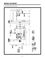
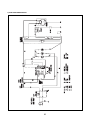
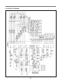
1. Refer to Circuit Diagram (point 4).
2. Secondary side voltage of the low voltage transformer changes in proportion to fluctuation of power source voltage.
3. The allowable tolerance of the secondary voltage is within ± 5% of nominal voltage.
2. Voltage check
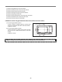
• Key check point
NO
CHECK POINT
REMARK
1
IC 1 PIN 2, 21, 30, 34
-5 VDC
2
IC 1 PIN 35
T:16.7ms(60Hz)
3
IC 1 PIN 31 OR 32
T:250ns(4MHz)
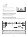
• Check method
NO
MEASURE POINT
1
MP1
2
MP2
WAVE FORM
REMEDY
REMARK
DC -5V±0.25V
Replace VL1, EC1
NO LOAD
DC -12V±2.0V
Replace EC2, D12, 13, 14
NO LOAD
NOTE :
Each measure point must be measured with GND points.
26